JP5347602B2 - Blood processing equipment - Google Patents
Blood processing equipment Download PDFInfo
- Publication number
- JP5347602B2 JP5347602B2 JP2009062962A JP2009062962A JP5347602B2 JP 5347602 B2 JP5347602 B2 JP 5347602B2 JP 2009062962 A JP2009062962 A JP 2009062962A JP 2009062962 A JP2009062962 A JP 2009062962A JP 5347602 B2 JP5347602 B2 JP 5347602B2
- Authority
- JP
- Japan
- Prior art keywords
- blood
- hollow fiber
- gas exchange
- fiber membrane
- processing apparatus
- Prior art date
- Legal status (The legal status is an assumption and is not a legal conclusion. Google has not performed a legal analysis and makes no representation as to the accuracy of the status listed.)
- Expired - Fee Related
Links
Images


Landscapes
- External Artificial Organs (AREA)
Description
本発明は、心臓血管手術における体外循環に用いられ、血液に酸素を供給し二酸化炭素を除去しながら、増加した血液中の水分を除去して正常な水分量の血液にするための血液処理装置に関する。 The present invention is used for extracorporeal circulation in cardiovascular surgery, and is a blood processing apparatus for removing the increased water content into a normal amount of blood while supplying oxygen to the blood and removing carbon dioxide. About.
体外循環を伴う心臓血管手術では、輸血の低減や、抹消循環の改善、血液損傷の低減などを目的として、希釈体外循環法を用いることが、一般的である。しかし、補液や心筋保護液などの体外循環回路内への流入に伴い、高度希釈が発生すると、膠質浸透圧の低下による浮腫の発生や、ヘマトクリットの低下によるガス交換能の低下が発生するため、必要に応じ、血液濃縮器などを用いて、余剰水分を排出(除水)する操作が必要となる。 In cardiovascular surgery involving extracorporeal circulation, it is common to use a dilute extracorporeal circulation method for the purpose of reducing blood transfusion, improving peripheral circulation, and reducing blood damage. However, when high dilution occurs due to inflow of extracorporeal fluid or myocardial protective fluid into the extracorporeal circuit, edema will occur due to decreased colloid osmotic pressure, and gas exchange capacity will decrease due to decreased hematocrit. If necessary, an operation for discharging (water removal) excess water using a blood concentrator or the like is required.
従って、希釈体外循環法を行なうためには、血液に酸素を供給し二酸化炭素を除去するガス交換を行うための人工肺と、除水を行なうための血液濃縮器を併用する必要があり、従来、両装置をそれぞれ分離配置した体外循環回路が知られていた。しかし、人工肺の回路と並列に血液濃縮器の回路が必要であるため、回路が複雑になり、血液処理操作が煩雑であった。また、並ループ回路の構成であるため、プライミング量(血液充填量)が多くなり、生体負荷が大きくなる欠点があった。 Therefore, in order to perform the extracorporeal circulation method, it is necessary to use an oxygenator for performing gas exchange for supplying oxygen to blood and removing carbon dioxide, and a blood concentrator for performing dehydration. An extracorporeal circuit in which both devices are separately arranged has been known. However, since a blood concentrator circuit is required in parallel with the artificial lung circuit, the circuit is complicated and the blood processing operation is complicated. In addition, since the configuration is a parallel loop circuit, there is a disadvantage that the priming amount (blood filling amount) increases and the biological load increases.
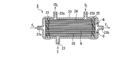
これに対して、特許文献1には、人工肺と血液濃縮器を一体化して共通のハウジング内に収納した構成により、上記のような問題を解決することが記載されている。この血液処理装置について、図4を参照して説明する。この血液処理装置Aは、円筒状のハウジング20内に、人工肺Bと血液濃縮器Cとが直列に配列され収容された構成を有する。
On the other hand, Patent Document 1 describes that the above-described problems are solved by a configuration in which an artificial lung and a blood concentrator are integrated and housed in a common housing. This blood processing apparatus will be described with reference to FIG. This blood processing apparatus A has a configuration in which an artificial lung B and a blood concentrator C are arranged and accommodated in a
ハウジング20の長手方向の初端側に未処理血液F1の導入口となる血液導入ポート21aが設けられ、終端側に処理済血液F2の排出口となる血液出口ポート21bが設けられている。人工肺Bが収納されている領域には、血液導入ポート21aの近傍の外周位置に二酸化炭素の排出口となるガス出口ポート22aが、人工肺Bの領域の下流側の外周位置には酸素の給気口となるガス入口ポート22bが設けられている。血液濃縮器Cが収納されている領域の外周位置には、濾過液Eの除水口となる排水ポート23が設けられている。
A
人工肺Bは、シリコーン膜よりなる多数の第1中空糸膜24により構成され、その両端が、ポリウレタン等の硬化性樹脂25により気密に固着されている。血液濃縮器Cは、透水速度が大きくタンパク質阻止率の高いポリスルホン膜よりなる多数の第2中空糸膜26により構成され、その両端が、ポリウレタン等の硬化性樹脂25により気密に固着されている。
The artificial lung B is composed of a large number of first
上記構成により、人工肺Bの第1中空糸膜24内を軸方向に流通する血液に、ガス入口ポート22bから酸素を供給し、この酸素とガス交換された血液中の二酸化炭素をガス出口ポート22aから排出する。また、血液濃縮器Cの第2中空糸膜26内を軸方向に流通する血液から、水分が径方向へ透過されて、排水ポート23から排出される。
With the above configuration, oxygen is supplied from the
このように、第1中空糸膜24と第2中空糸膜26がハウジング20内に直列に配置されることにより、血液導入ポート21aから流入した未処理血液F1は、人工肺Bの領域で酸素を供給され、二酸化炭素を排出した後、血液濃縮器Cの領域で余分な水分が除水されて、血液出口ポート21bから処理済血液F2として流出する。
As described above, the first
また、特許文献2には、人工肺と血液濃縮器を一体化して共通のハウジング内に収納した、他の構成が記載されている。これについて図5を参照して説明する。この血液処理装置Aは、円筒状のハウジング20内に、人工肺Bを構成する多数の第1中空糸膜24と、血液濃縮器Cを構成する多数の第2中空糸膜26とが、互いに並列状に収納された構成を有する。なお、図4の血液処理装置と同様の要素については、同一の参照符号を付して、説明の繰り返しを避ける。
ハウジング20の長手方向の初端側に血液導入ポート21aが、終端側に血液出口ポート21bが設けられている。人工肺Bとして機能させる側の外周面には、二酸化炭素の排出口となるガス出口ポート22aと、酸素の給気口となるガス入口ポート22bが設けられている。血液濃縮器Cとして機能させる側の外周面には、濾過液Eの除水口となる排水ポート23が設けられている。
A
上記構成により、第1中空糸膜24内を軸方向に流通する血液に、ガス入口ポート22bから酸素を供給し、ガス交換された血液中の二酸化炭素をガス出口ポート22aから排出する。また、第2中空糸膜26内を軸方向に流通する血液から、水分が径方向へ透過されて、排水ポート23から排出される。
With the above configuration, oxygen is supplied from the
上記特許文献1に記載の構成の場合、人工肺と血液濃縮器の中空糸膜の軸方向が直列に配列され、血液が中空糸膜中を通過する経路が長くなる。そのため、血液流の圧力損失が大きい。また、後述するような内部灌流方式を採用しているため、低灌流量(または低灌流下)でしか利用することができず、更に血液濃縮器による除水のためには、排水ポート23から陰圧を付与する必要があり、装置を構成する要素が多くなるとの問題点があった。
In the case of the configuration described in Patent Document 1, the axial directions of the artificial lung and the hollow fiber membrane of the blood concentrator are arranged in series, and the path through which blood passes through the hollow fiber membrane becomes long. Therefore, the pressure loss of the blood flow is large. Further, since an internal perfusion system as described later is adopted, it can be used only at a low perfusion rate (or under a low perfusion), and further from the
また、特許文献2に記載の構成の場合、血液導入ポート21aから流入した血液が、人工肺の領域と血液濃縮器の領域に分流されるため、灌流血液量の一部のみがガス交換され、また、残りの一部のみが除水されることになる。したがって、血液処理装置による処理後の血液中には、処理状態が異なった血液が混ざることになり、好ましくない。また、血液濃縮器側では、血液が濃縮により粘度が上昇して、流れなくなる可能性がある。
Further, in the case of the configuration described in
また、血液濃縮器は特許文献1及び2に示されるように、効率の面から、血液浄化器と同様、中空糸内部灌流方式を用いるのが一般的である。すなわち、中空糸膜の内腔に血液を流通させ、中空糸膜の外表面側に除水する。これは、低灌流でも膜間圧力(T.M.P.)を高くすることができ、除水効率を向上できるからである。
In addition, as shown in
その反面、圧力損失が高くなるため、高灌流下での使用には適さない(500mL/min以下)。従って、高灌流で使用する人工心肺の場合は、低灌流の別回路中に血液濃縮器を設ける必要があった。 On the other hand, since the pressure loss is high, it is not suitable for use under high perfusion (500 mL / min or less). Therefore, in the case of a heart-lung machine used for high perfusion, it is necessary to provide a blood concentrator in a separate circuit for low perfusion.
以上の問題を考慮して、本発明は、人工肺と血液濃縮器が共通のハウジング内に収納され、血液流の圧力損失が少ないガス交換及び除水が可能であって、人工肺に適した高灌流下での使用が可能な血液処理装置を提供することを目的とする。 In consideration of the above problems, the present invention is suitable for an artificial lung because the oxygenator and the blood concentrator are housed in a common housing, and can perform gas exchange and water removal with low pressure loss of the blood flow. An object of the present invention is to provide a blood treatment apparatus that can be used under high perfusion.
上記課題を解決するために、本発明の血液処理装置は、除水用中空糸膜を平面状に複数本配列し複数層に積層した中空糸束により形成された血液濃縮モジュールと、ガス交換用中空糸膜を平面状に複数本配列し複数層に積層した中空糸束により形成されたガス交換モジュールと、前記血液濃縮モジュール及び前記ガス交換モジュールが積層状態に各々収納された直列に配列された血液濃縮部及びガス交換部を有するハウジングと、前記除水用中空糸膜の一端の開口は露出させ他端の開口は閉鎖し、前記ガス交換用中空糸膜の両端の開口は露出させた状態で前記血液濃縮モジュール及び前記ガス交換モジュールの両端部を封止し、前記両端部の中間の領域に、前記除水用中空糸膜及び前記ガス交換用中空糸膜の軸方向と交差する方向に延在して前記血液濃縮部及び前記ガス交換部を通過する血液流路を形成している封止部材と、前記血液流路の両端に面して前記ハウジングに設けられた血液流入ポート及び血液流出ポートと、前記封止部材から露出した前記除水用中空糸膜の前記一端の開口に面して前記ハウジングに設けられた排水ポートと、前記封止部材から露出した前記ガス交換用中空糸膜の両端の開口に面して前記ハウジングに設けられた給気ポート及び排気ポートとを備え、前記ハウジングの内壁により、前記除水用中空糸膜の前記閉鎖された他端の開口に面する領域の空間を封鎖したことを特徴とする。
In order to solve the above problems, the blood treatment apparatus of the present invention comprises a blood concentration module formed by a hollow fiber bundle in which a plurality of hollow fiber membranes for water removal are arranged in a plane and laminated in a plurality of layers, and a gas exchange device. A gas exchange module formed by a hollow fiber bundle in which a plurality of hollow fiber membranes are arranged in a plane and laminated in a plurality of layers, and the blood concentration module and the gas exchange module are arranged in series, each housed in a laminated state A housing having a blood concentration part and a gas exchange part, and an opening at one end of the hollow fiber membrane for water removal is exposed, an opening at the other end is closed, and openings at both ends of the hollow fiber membrane for gas exchange are exposed. Sealing both ends of the blood concentration module and the gas exchange module in a direction intersecting with the axial direction of the dewatering hollow fiber membrane and the gas exchange hollow fiber membrane in an intermediate region between the both ends. Extended A sealing member forming a blood flow path passing through the blood concentration part and the gas exchange part, a blood inflow port and a blood outflow port provided in the housing facing both ends of the blood flow path, a drain port provided in the housing facing the opening of the one end of the dewatering hollow fiber film exposed from the sealing member, both ends of the gas exchange hollow fiber membrane exposed from the sealing member An air supply port and an exhaust port provided in the housing facing the opening, and a space in a region facing the opening of the closed other end of the dewatering hollow fiber membrane by the inner wall of the housing it said that the blockade was.
上記構成の血液処理装置では、同一ハウジング内に血液濃縮モジュールとガス交換モジュールとが積層状態に収納され、血液流路に対して直列に配列された状態となっており、外部灌流方式を適用できる。 In the blood processing apparatus having the above configuration, the blood concentration module and the gas exchange module are housed in a stacked state in the same housing, and are arranged in series with respect to the blood flow path, so that an external perfusion method can be applied. .
従って、血液流は血液濃縮モジュール及びガス交換モジュールの中空糸膜の外表面側に沿って順次通過して、血液濃縮とガス交換を同一ハウジング内で機能させることができ、しかも、血液は中空糸膜外を流通するので、圧力損失は少ない。そのため、人工肺に適した高灌流下での使用が可能である。 Therefore, the blood flow sequentially passes along the outer surface side of the hollow fiber membrane of the blood concentration module and the gas exchange module, and blood concentration and gas exchange can function in the same housing, and the blood is hollow fiber. Since it flows outside the membrane, there is little pressure loss. Therefore, it can be used under high perfusion suitable for artificial lungs.
本発明の血液処理装置は、上記構成を基本として、以下のような態様をとることができる。 The blood processing apparatus of the present invention can take the following aspects based on the above-described configuration.
すなわち、前記ガス交換部が、前記血液濃縮部よりも前記血液流入ポートに近い側に配置されることが好ましい。
That is, it is preferable that the gas exchange part is disposed closer to the blood inlet port than the blood concentrating part .
また、前記血液流路は、その流路方向に直交する断面が円形であることが好ましい。 Further, the blood channel preferably has a circular cross section perpendicular to the channel direction.
また前記血液濃縮モジュール及び前記ガス交換モジュールを構成する各中空糸の軸方向が、前記血液流路の流れ方向と直交し、且つそれぞれの中空糸の軸方向が互いに交差するように配置することができる。 The axial direction of each hollow fiber constituting the blood concentration module and the gas exchange module may be arranged so as to be orthogonal to the flow direction of the blood flow path and the axial directions of the hollow fibers intersect each other. it can.
また、前記ガス交換用中空糸膜はポリプロプレン膜を用いて形成され、前記除水用中空糸膜は、ポリスチロール膜、ポリエーテルサルフォン膜、ポリメチルメタクリレート膜、またはセルロース・アセテート膜を用いて形成されている構成とすることができる。 Further, the gas exchange hollow fiber membrane is formed using a polypropylene membrane, and the water removal hollow fiber membrane is a polystyrene film, a polyether sulfone film, a polymethyl methacrylate film, or a cellulose acetate film. It can be set as the structure formed.
また、前記血液濃縮部が前後に複数段設けられて、血液を段階的に濃縮する構造を有することができる。 Further, the blood concentration part may have a structure in which a plurality of stages are provided on the front and rear sides to concentrate the blood stepwise.
以下、本発明の実施形態について図面を参照しながら説明する。 Hereinafter, embodiments of the present invention will be described with reference to the drawings.
(実施の形態1)
本発明の実施の形態1における血液処理装置の断面図を、図1に示す。図2Aは、その要部を一部断面で示した斜視図である。この血液処理装置は、血液濃縮モジュール1と、ガス交換モジュール2とを有する。血液濃縮モジュール1は、水分は透過するがタンパク質は阻止する除水用中空糸膜1aを複数本配列した中空糸束により形成される。ガス交換モジュール2は、ガス交換能に優れたガス交換用中空糸膜2aを複数本配列して形成された中空糸束により形成される。
(Embodiment 1)
A cross-sectional view of the blood treatment apparatus according to Embodiment 1 of the present invention is shown in FIG. FIG. 2A is a perspective view showing the main part in a partial cross section. This blood processing apparatus has a blood concentration module 1 and a
ハウジング3は、血液濃縮モジュール1を収納した血液濃縮部4、及びガス交換モジュール2を収納したガス交換部5を有する。除水用中空糸膜1aとガス交換用中空糸膜2aとは、互いに積層状態に配置されている。すなわち、図1の例では、除水用中空糸膜1aの軸方向とガス交換用中空糸膜2aの軸方向が平行である。但し、除水用中空糸膜とガス交換用中空糸膜とが積層構造を採っておれば、各中空糸膜の軸方向は、必ずしも互いに平行である必要はない。例えば、図2Bに示すように、除水用中空糸膜及びガス交換用中空糸膜が血液流路の向きと実質的に直交する状態に配置され、且つ除水用中空糸膜がガス交換用中空糸膜に対して交差した態様であっても良い。それにより、各中空糸膜束の間に形成される空間を少なくすることができるので、好ましい。
The
両モジュール1、2の両端部は、高分子ポッティング材、例えばポリウレタン、シリコーン、エポキシ樹脂等により形成された封止部材6により封止されている。封止部材6により形成された構造が判りやすいように、ハウジング3を取り除いた状態を、一部断面にして図2Aに示す。
Both end portions of both
この封止構造において、除水用中空糸膜1aの一端の開口は閉鎖されることなく露出しているが、他端の開口は閉鎖されている。また、ガス交換用中空糸膜2aの両端の開口7は、封止部材6により閉鎖されることなく露出している。従って、ガス交換用中空糸膜2aの内部には、中空糸膜の両端に亘る貫通したガス流路が確保されている。さらに、両モジュール1、2の両端部の中間の領域において、封止部材6は、血液流路8を形成する貫通孔を有する。血液流路8は、除水用中空糸膜1a及びガス交換用中空糸膜2aの軸方向と交差する方向に延在して血液濃縮部4及びガス交換部5を通過するように形成され、その流路方向に直交する断面形状が円形である。
In this sealing structure, the opening at one end of the water removal
ハウジング3は更に、血液流路8の両端に面して血液流入ポート9及び血液流出ポート10を有する。また、封止部材6から露出した除水用中空糸膜1aの一端の開口に面して、血液濃縮部4の側部に排水ポート11が設けられている。また、封止部材6から露出したガス交換用中空糸膜2aの両端の開口に面して、ガス交換部5の側部に給気ポート12及び排気ポート13が設けられている。
The
更に、血液濃縮部4とガス交換部5の境界部では、ハウジング3の内壁に隔壁14が設けられている。それにより、それにより、血液濃縮部4では、排水ポート11に面した領域に、他から隔離された空間が形成されている。また、ガス交換部5の両端では、給気ポート12及び排気ポート13にそれぞれ面した領域にも、他から隔離された空間が形成されている。従って、排水ポート11、給気ポート12及び排気ポート13は、それぞれ独立して機能する。
Furthermore, a
また、図に示していないが、血液濃縮部4とガス交換部5の間に、熱交換器を組込むことで、血液濃縮した直後の血液を加温、または冷却することが可能となり、さらに加温/冷却した血液をガス交換できるので、効率良く加温でき、気泡の発生を抑止できる。
Although not shown in the figure, by incorporating a heat exchanger between the blood concentration unit 4 and the
以上のとおり、本実施の形態の血液処理装置では、血液濃縮モジュール1とガス交換モジュール2とが積層状態に配置され、血液流路8に対して直列に配列された状態となってる。そして、中空糸膜1a、2aの外表面側を血液が流通し、除水用中空糸膜1aの内部を介して除水され、ガス交換用中空糸膜2aの内部を酸素含有ガスが流通する、いわゆる外部灌流方式が用いられる。
As described above, in the blood processing apparatus of the present embodiment, the blood concentration module 1 and the
従って、血液濃縮とガス交換を同一ハウジング内で容易に機能させることができ、しかも、血液は中空糸膜中を通過しないので、内部灌流方式に比べ圧力損失は少ない。そのため、人工肺に適した高灌流下で、除水のための別回路を設けること無く、使用することが可能である。なお、外部灌流方式では、内部灌流方式に比べ除水効率が低下する。これに対しては、外部灌流方式では圧力損失が低減されるので、高灌流量で使用すれば、除水効率の低下はさほど問題とならない。 Therefore, blood concentration and gas exchange can be easily functioned in the same housing, and since blood does not pass through the hollow fiber membrane, pressure loss is small compared to the internal perfusion method. Therefore, it can be used without providing a separate circuit for water removal under high perfusion suitable for an artificial lung. In the external perfusion method, the water removal efficiency is lower than that in the internal perfusion method. On the other hand, since the pressure loss is reduced in the external perfusion method, the decrease in the water removal efficiency is not a problem if used at a high perfusion rate.
また、本実施の形態のように、血液濃縮部4が、ガス交換部5よりも血液流入ポート9に近い側に配置された構造にすると、次のような利点がある。すなわち、血液流が、最初に血液濃縮部4を通過後に、ガス交換部5を通過することにより、より高いTMPが得られる。しかも、血液が濃縮された後にガス交換されるので、ガス交換性能が向上する。
Moreover, when the blood concentration part 4 is arranged on the side closer to the
さらに、外部灌流方式とすることにより、血液濃縮部4における除水のために陰圧を付与することが不要となる。 Furthermore, by using the external perfusion method, it is not necessary to apply a negative pressure for water removal in the blood concentration unit 4.
また、積層型を採用した本実施の形態の構造は、コアに中空糸を巻きつけるワインド型人工肺に比べ、異なる素材の中空糸膜を同一ハウジング内に構成することが容易である。しかも、中空糸膜内部の流路について、独立した区画を設けることが容易であるので、血液濃縮モジュールとガス交換モジュールを併用して、外部灌流方式を適用することが容易である。 In addition, the structure of the present embodiment adopting the laminated type can easily form the hollow fiber membranes of different materials in the same housing as compared with the wind type artificial lung in which the hollow fiber is wound around the core. And since it is easy to provide an independent division about the flow path inside a hollow fiber membrane, it is easy to apply an external perfusion system using a blood concentration module and a gas exchange module together.
ガス交換モジュール2に用いるガス交換用中空糸膜2aの素材としては、例えば、ポリプロピレン膜を用いることができる。
As a raw material of the gas exchange
血液濃縮モジュール1に用いる除水用中空糸膜1aの素材としては、例えば、PS(ポリスチロール)樹脂、PES(ポリエーテルサルフォン)樹脂、PMMA(ポリメチルメタクリレート)樹脂、CA(セルロース・アセテート)樹脂などをそのまま利用しても良いし、その他の材料でも良い。
Examples of the material for the water removal
これらの材質による中空糸膜を用いた血液濃縮器は、内部灌流方式に最適な構造、例えば、中空糸内面あるいは中間層側に緻密層を配し、除水効率を長期間維持させる構造が多い。そのため、本実施の形態のように外部灌流方式を用いた場合、従来品を用いると、中空糸外面側に血液成分が入り込み、多少除水効率が低下する可能性がある。 Blood concentrators using hollow fiber membranes made of these materials are most suitable for the internal perfusion system, for example, a structure in which a dense layer is disposed on the inner surface or intermediate layer side of the hollow fiber to maintain water removal efficiency for a long period of time. . Therefore, when the external perfusion method is used as in the present embodiment, if a conventional product is used, blood components may enter the outer surface of the hollow fiber, and the water removal efficiency may be somewhat reduced.
しかし、内部灌流方式に比べ、外部灌流方式では圧力損失を低減することが可能であるので、高灌流量でも使用可能であり、外部灌流方式を用いることに起因する除水効率の低下はさほど問題とならない。例えば、内部灌流方式の場合の灌流量100〜500mL程度に比べ、100mL程度から7〜8L/minと、はるかに高灌流量を得ることができる。もちろん、外部灌流に適した構造、例えば、外部側より緻密層を配する構造とした中空糸膜を用いてもよい。 However, compared with the internal perfusion method, the pressure loss can be reduced with the external perfusion method, so it can be used even at high perfusion rates, and the reduction in water removal efficiency due to the use of the external perfusion method is a problem. Not. For example, compared with the perfusion rate of about 100 to 500 mL in the case of the internal perfusion method, a much higher perfusion rate of about 100 mL to 7 to 8 L / min can be obtained. Of course, a hollow fiber membrane having a structure suitable for external perfusion, for example, a structure in which a dense layer is disposed from the outside may be used.
血液流路の形態は、直線流路で、流路断面形状は四角でもよいが、上述の実施の形態ように円形流路を採用した方が、偏流が抑制され、血液流路の周縁部でも(血流が)停滞せずにガス交換ができるため、高いガス交換効率が得られる。 The shape of the blood channel may be a straight channel, and the channel cross-sectional shape may be a square. However, if the circular channel is used as in the above embodiment, uneven flow is suppressed and the peripheral portion of the blood channel is also used. Since gas can be exchanged without stagnation (blood flow), high gas exchange efficiency can be obtained.
また、前後に三層以上の構造として、段階的に濃縮する構造としてもよい。 Moreover, it is good also as a structure condensed in steps as a structure of three or more layers before and after.
(実施の形態2)
本発明の実施の形態2における血液処理装置の断面図を、図3に示す。この血液処理装置は、構成要素は実施の形態1における装置と同様であり、血液の流動方向に対して上流側にガス交換部5が配置され、下流側に血液濃縮部4が配置された点が、実施の形態1と相違する。従って、実施の形態1の場合と同様の要素については同一の参照符号を付して、説明の繰り返しを省略する。
(Embodiment 2)
FIG. 3 shows a cross-sectional view of the blood processing apparatus according to
図3に示すとおり、ガス交換部5が、血液濃縮部4よりも血液流入ポート9に近い側に配置され、実施の形態1と同様、ガス交換モジュール2と血液濃縮モジュール1とが積層状態に配置されている。従って、ガス交換モジュール2と血液濃縮モジュール1とが、血液流路8に対して直列に配列された状態となってる。そして、中空糸膜1a、1bの外表面側を血液が流通し、ガス交換用中空糸膜2aの内部を酸素含有ガスが流通し、除水用中空糸膜1aの内部を介して除水される外部灌流方式を用いる構造となっている。
As shown in FIG. 3, the
本実施の形態のように血液流が、まずガス交換部5を通過後に、血液濃縮部4を通過することにより、人工肺内の圧力損失は、実施の形態1の場合より低減される利点がある。但し、血液濃縮部4において、水引効果と同時に、若干のガス排出が発生する可能性がある。ガス交換により血液中に取り込まれた酸素ガスが放出されると、実質的にガス交換効率が低減する。
As the blood flow first passes through the
本発明の血液処理装置によれば、血液濃縮とガス交換を同一ハウジング内で機能させることができ、しかも、血液流の圧力損失は少ないので高灌流下での使用が可能であり、また現行行っているような除水のための別回路の形成無しに体外循環が行えるため、有用である。 According to the blood processing apparatus of the present invention, blood concentration and gas exchange can be functioned in the same housing, and the pressure loss of the blood flow is small, so that it can be used under high perfusion, and is currently performed. This is useful because extracorporeal circulation can be performed without forming a separate circuit for water removal.
1 血液濃縮モジュール
1a 除水用中空糸膜
2 ガス交換モジュール
2a ガス交換用中空糸膜
3 ハウジング
4 血液濃縮部
5 ガス交換部
6 封止部材
7 開口
8 血液流路
9 血液流入ポート
10 血液流出ポート
11 排水ポート
12 給気ポート
13 排気ポート
14 隔壁
20 ハウジング
21a 血液導入ポート
21b 血液出口ポート
22a ガス出口ポート
22b ガス入口ポート
23 排水ポート
24 第1中空糸膜
25 硬化性樹脂
26 第2中空糸膜
A 血液処理装置
B 人工肺
C 血液濃縮器
E 濾過液
F1 未処理血液
F2 処理済血液
DESCRIPTION OF SYMBOLS 1
Claims (6)
ガス交換用中空糸膜を平面状に複数本配列し複数層に積層した中空糸束により形成されたガス交換モジュールと、
前記血液濃縮モジュール及び前記ガス交換モジュールが積層状態に各々収納され直列に配列された血液濃縮部及びガス交換部を有するハウジングと、
前記除水用中空糸膜の一端の開口は露出させ他端の開口は閉鎖し、前記ガス交換用中空糸膜の両端の開口は露出させた状態で前記血液濃縮モジュール及び前記ガス交換モジュールの両端部を封止し、前記両端部の中間の領域に、前記除水用中空糸膜及び前記ガス交換用中空糸膜の軸方向と交差する方向に延在して前記血液濃縮部及び前記ガス交換部を通過する血液流路を形成している封止部材と、
前記血液流路の両端に面して前記ハウジングに設けられた血液流入ポート及び血液流出ポートと、
前記封止部材から露出した前記除水用中空糸膜の前記一端の開口に面して前記ハウジングに設けられた排水ポートと、
前記封止部材から露出した前記ガス交換用中空糸膜の両端の開口に面して前記ハウジングに設けられた給気ポート及び排気ポートとを備え、
前記ハウジングの内壁により、前記除水用中空糸膜の前記閉鎖された他端の開口に面する領域の空間を封鎖したことを特徴とする血液処理装置。 A blood concentration module formed of a hollow fiber bundle in which a plurality of hollow fiber membranes for water removal are arranged in a plane and laminated in a plurality of layers ;
A gas exchange module formed by a hollow fiber bundle in which a plurality of gas exchange hollow fiber membranes are arranged in a plane and laminated in a plurality of layers ;
A housing having a blood concentration unit and a gas exchange unit in which the blood concentration module and the gas exchange module are housed in a stacked state and arranged in series ;
One end of the dewatering hollow fiber membrane is exposed and the other end is closed, and both ends of the gas exchange hollow fiber membrane are exposed, and both ends of the blood concentration module and the gas exchange module are exposed. The blood concentrating part and the gas exchange extending in a direction intersecting the axial direction of the dewatering hollow fiber membrane and the gas exchange hollow fiber membrane in an intermediate region between the both ends. A sealing member forming a blood flow path passing through the section;
A blood inflow port and a blood outflow port provided in the housing facing both ends of the blood flow path;
A drain port provided in the housing facing the opening of the one end of the dewatering hollow fiber film exposed from the sealing member,
An air supply port and an exhaust port provided in the housing facing openings at both ends of the gas exchange hollow fiber membrane exposed from the sealing member ;
A blood processing apparatus , wherein an inner wall of the housing seals a space in a region facing the opening of the closed other end of the dewatering hollow fiber membrane .
Priority Applications (1)
| Application Number | Priority Date | Filing Date | Title |
|---|---|---|---|
| JP2009062962A JP5347602B2 (en) | 2009-03-16 | 2009-03-16 | Blood processing equipment |
Applications Claiming Priority (1)
| Application Number | Priority Date | Filing Date | Title |
|---|---|---|---|
| JP2009062962A JP5347602B2 (en) | 2009-03-16 | 2009-03-16 | Blood processing equipment |
Publications (2)
| Publication Number | Publication Date |
|---|---|
| JP2010213852A JP2010213852A (en) | 2010-09-30 |
| JP5347602B2 true JP5347602B2 (en) | 2013-11-20 |
Family
ID=42973352
Family Applications (1)
| Application Number | Title | Priority Date | Filing Date |
|---|---|---|---|
| JP2009062962A Expired - Fee Related JP5347602B2 (en) | 2009-03-16 | 2009-03-16 | Blood processing equipment |
Country Status (1)
| Country | Link |
|---|---|
| JP (1) | JP5347602B2 (en) |
Cited By (1)
| Publication number | Priority date | Publication date | Assignee | Title |
|---|---|---|---|---|
| JP2912464B2 (en) | 1991-03-12 | 1999-06-28 | ライト工業株式会社 | Ground stabilization method |
Families Citing this family (2)
| Publication number | Priority date | Publication date | Assignee | Title |
|---|---|---|---|---|
| CN111032106B (en) * | 2017-08-15 | 2023-02-10 | 马里兰大学巴尔的摩 | Dual chamber gas exchanger for respiratory support |
| CN113350596B (en) * | 2021-07-19 | 2025-12-30 | 北京航空航天大学 | Oxygenators and Extracorporeal Membrane Oxygenation Devices |
Family Cites Families (7)
| Publication number | Priority date | Publication date | Assignee | Title |
|---|---|---|---|---|
| JPS6247369A (en) * | 1985-08-26 | 1987-03-02 | 株式会社 日本メデイカル・サプライ | Blood treatment apparatus |
| JPS6247368A (en) * | 1985-08-26 | 1987-03-02 | 株式会社 日本メデイカル・サプライ | Blood treatment apparatus |
| JPH04193178A (en) * | 1990-11-27 | 1992-07-13 | Mitsubishi Rayon Co Ltd | Hollow fiber membrane oxygenator module |
| JPH06245997A (en) * | 1993-02-24 | 1994-09-06 | Hikari Nakanishi | Blood concentrating device-containing artificial lung |
| JPH09220282A (en) * | 1996-02-20 | 1997-08-26 | Senko Ika Kogyo Kk | Artificial lung |
| JP5168777B2 (en) * | 2005-11-24 | 2013-03-27 | 株式会社ジェイ・エム・エス | Hollow fiber membrane oxygenator |
| DE102009008601A1 (en) * | 2009-02-12 | 2010-08-19 | Novalung Gmbh | Device for the treatment of a biological fluid |
-
2009
- 2009-03-16 JP JP2009062962A patent/JP5347602B2/en not_active Expired - Fee Related
Cited By (1)
| Publication number | Priority date | Publication date | Assignee | Title |
|---|---|---|---|---|
| JP2912464B2 (en) | 1991-03-12 | 1999-06-28 | ライト工業株式会社 | Ground stabilization method |
Also Published As
| Publication number | Publication date |
|---|---|
| JP2010213852A (en) | 2010-09-30 |
Similar Documents
| Publication | Publication Date | Title |
|---|---|---|
| JP4795536B2 (en) | Potting a tubular bundle into the housing | |
| ES2458140T3 (en) | MECS dialyzer | |
| CN107666921B (en) | Apparatus with inlet section for processing biological liquids | |
| US10286137B2 (en) | Oxygenator module, oxygenator and production method | |
| JPH0286817A (en) | Hollow yarn-type fluid treating device | |
| JP4026037B2 (en) | Hollow fiber membrane gas-liquid gas exchange device and gas exchange method thereof | |
| JPS60193469A (en) | Hollow yarn membrane type artificial lung | |
| US20220409797A1 (en) | Extracorporeal blood conditioning devices and methods | |
| JP5347602B2 (en) | Blood processing equipment | |
| EP1557185B1 (en) | Device for treating blood for extracorporeal circulation | |
| JP5347601B2 (en) | Blood processing equipment | |
| CN108697987B (en) | System and method for filtering fluids | |
| JP6382005B2 (en) | Extracorporeal circuit | |
| JP4328902B2 (en) | Online large-volume fluid replacement hemodialyzer | |
| WO2016006041A1 (en) | Blood purifier | |
| CN114053504A (en) | Square medical hemodialyzer | |
| JP2000070360A (en) | Hollow fiber membrane type dialyzer | |
| US11707559B2 (en) | Extracorporeal oxygenator with integrated air removal system | |
| JP2022103007A (en) | Solution treatment method and solution treatment device | |
| JPS6129360A (en) | Artificial lung having dialytic function | |
| CN114053505A (en) | Manufacturing method of square hemodialyzer and dialysis method | |
| JP4237534B2 (en) | Blood purifier | |
| JP6184154B2 (en) | Blood purifier | |
| CN115998975A (en) | A housing device for a dialysate flow path | |
| WO2019077543A1 (en) | Integrated fluid treatment device |
Legal Events
| Date | Code | Title | Description |
|---|---|---|---|
| A621 | Written request for application examination |
Free format text: JAPANESE INTERMEDIATE CODE: A621 Effective date: 20120126 |
|
| A977 | Report on retrieval |
Free format text: JAPANESE INTERMEDIATE CODE: A971007 Effective date: 20130322 |
|
| A131 | Notification of reasons for refusal |
Free format text: JAPANESE INTERMEDIATE CODE: A131 Effective date: 20130328 |
|
| A521 | Request for written amendment filed |
Free format text: JAPANESE INTERMEDIATE CODE: A523 Effective date: 20130522 |
|
| TRDD | Decision of grant or rejection written | ||
| A01 | Written decision to grant a patent or to grant a registration (utility model) |
Free format text: JAPANESE INTERMEDIATE CODE: A01 Effective date: 20130723 |
|
| A61 | First payment of annual fees (during grant procedure) |
Free format text: JAPANESE INTERMEDIATE CODE: A61 Effective date: 20130805 |
|
| R150 | Certificate of patent or registration of utility model |
Ref document number: 5347602 Country of ref document: JP Free format text: JAPANESE INTERMEDIATE CODE: R150 Free format text: JAPANESE INTERMEDIATE CODE: R150 |
|
| R250 | Receipt of annual fees |
Free format text: JAPANESE INTERMEDIATE CODE: R250 |
|
| R250 | Receipt of annual fees |
Free format text: JAPANESE INTERMEDIATE CODE: R250 |
|
| R250 | Receipt of annual fees |
Free format text: JAPANESE INTERMEDIATE CODE: R250 |
|
| R250 | Receipt of annual fees |
Free format text: JAPANESE INTERMEDIATE CODE: R250 |
|
| R250 | Receipt of annual fees |
Free format text: JAPANESE INTERMEDIATE CODE: R250 |
|
| R250 | Receipt of annual fees |
Free format text: JAPANESE INTERMEDIATE CODE: R250 |
|
| R250 | Receipt of annual fees |
Free format text: JAPANESE INTERMEDIATE CODE: R250 |
|
| R250 | Receipt of annual fees |
Free format text: JAPANESE INTERMEDIATE CODE: R250 |
|
| LAPS | Cancellation because of no payment of annual fees |