JP5344946B2 - Electric compressor control device - Google Patents
Electric compressor control device Download PDFInfo
- Publication number
- JP5344946B2 JP5344946B2 JP2009027269A JP2009027269A JP5344946B2 JP 5344946 B2 JP5344946 B2 JP 5344946B2 JP 2009027269 A JP2009027269 A JP 2009027269A JP 2009027269 A JP2009027269 A JP 2009027269A JP 5344946 B2 JP5344946 B2 JP 5344946B2
- Authority
- JP
- Japan
- Prior art keywords
- motor
- speed
- torque
- electric compressor
- overload
- Prior art date
- Legal status (The legal status is an assumption and is not a legal conclusion. Google has not performed a legal analysis and makes no representation as to the accuracy of the status listed.)
- Expired - Fee Related
Links
Images


Abstract
Description
本発明は、車両用空調装置等に用いられる電動コンプレッサの制御装置に関する。 The present invention relates to a control device for an electric compressor used in a vehicle air conditioner or the like.
車両用空調装置において、電動コンプレッサは、冷媒をコンデンサ、エバポレータに循環させる冷凍サイクルの中で、エバポレータで気化した冷媒ガスを圧縮し高温、高圧のガスとしてコンデンサへ吐出する。コンデンサでは冷媒を凝縮液化させてエバポレータへ送出し、エバポレータにおいてこの冷媒を気化させる際に熱を吸収して室内を冷房する。
電動コンプレッサはインバータで制御される3相モータが駆動源として用いられている。
インバータはバッテリからの直流電流をスイッチング半導体素子でスイッチングしてモータへの電流を出力するが、モータ負荷が大きくなりスイッチング半導体素子を流れる電流(相電流)がその最大定格電流を越えるとスイッチング半導体素子の発熱が増大して破壊へ進む。
In a vehicle air conditioner, an electric compressor compresses refrigerant gas vaporized by an evaporator in a refrigeration cycle that circulates refrigerant to a condenser and an evaporator, and discharges the refrigerant gas as a high-temperature and high-pressure gas to the condenser. In the condenser, the refrigerant is condensed and sent to the evaporator, and when the refrigerant is vaporized in the evaporator, the refrigerant absorbs heat and cools the room.
The electric compressor uses a three-phase motor controlled by an inverter as a drive source.
The inverter switches the direct current from the battery with the switching semiconductor element and outputs the current to the motor. When the motor load increases and the current (phase current) flowing through the switching semiconductor element exceeds the maximum rated current, the switching semiconductor element The heat generation increases and destruction proceeds.
そこで、従来、電流がその最大定格電流を越えないようにする技術が提案されており、例えば特開2001−178190号公報には、電流が最大定格電流値に基づく第1の閾値以上になったときにモータの回転を停止するとともに、第1の閾値よりも小さい第2の閾値を設定して、電流が第2の閾値以上となったときモータの回転数を所定量減少させ、このあと電流が増加したときにはさらにモータの回転数を所定量減少させることにより、電流を第2の閾値よりも低く維持しようとするものが開示されている。
これは、第1の閾値以上になったときにモータの回転を停止するだけでは、それまで機能していた空調機能が急に停止して乗員に不快感を与えるので、そのような事態に至る前段階でモータの回転数を減少させることにより、モータ負荷を軽減して電流が第1の閾値に達するのを抑えようと図ったものである。
Therefore, conventionally, a technique for preventing the current from exceeding the maximum rated current has been proposed. For example, in Japanese Patent Laid-Open No. 2001-178190, the current is equal to or higher than a first threshold value based on the maximum rated current value. Sometimes the rotation of the motor is stopped and a second threshold value smaller than the first threshold value is set, and when the current exceeds the second threshold value, the rotation number of the motor is decreased by a predetermined amount. It is disclosed that the current is kept lower than the second threshold value by further decreasing the rotational speed of the motor when the value increases.
This is because, if the motor rotation is stopped only when it exceeds the first threshold value, the air conditioning function that has been functioning until then stops suddenly, causing discomfort to the occupant. By reducing the number of rotations of the motor in the previous stage, the motor load is reduced and an attempt is made to suppress the current from reaching the first threshold value.
ところで、モータについては負荷が過大になると速度指令に対してロータの回転が追随できなくなる脱調現象が生じことが知られており、脱調に至ると制御不能となって停止してしまい、運転を継続することができなくなる。
そこで、従来のスイッチング半導体素子の保護と同様に、負荷に閾値を設定して脱調に至る限界を越えないようにすることが考えられる。
ここで、電動コンプレッサのモータにかかる負荷はコンプレッサの冷媒吸入口と吐出口の間に生じる圧力差に依存し、圧力差が大きければ負荷は大きく、圧力差が小さければ負荷も小さい。そして、モータの回転数が低下すれば冷媒流量も低下して、結果として負荷が小さくなるという相関関係にある。
したがって、上記従来技術に倣えば、負荷が閾値に達して過負荷と判定されたらモータの回転数を低下させることとすればよい。
By the way, it is known that if the load is excessive, a step-out phenomenon will occur where the rotation of the rotor cannot follow the speed command. Can not continue.
Therefore, as with the conventional protection of switching semiconductor elements, it is conceivable to set a threshold value for the load so as not to exceed the limit leading to step-out.
Here, the load applied to the motor of the electric compressor depends on the pressure difference generated between the refrigerant suction port and the discharge port of the compressor. If the pressure difference is large, the load is large, and if the pressure difference is small, the load is small. And if the rotation speed of a motor falls, the refrigerant | coolant flow volume will also fall, and it has the correlation that a load becomes small as a result.
Therefore, according to the above prior art, when the load reaches the threshold value and is determined to be overloaded, the rotational speed of the motor may be reduced.
ところが、モータ負荷の実体であるコンプレッサ負荷の反応速度は遅く、モータの回転速度を減少させてもコンプレッサ負荷は直ちには低下せず、オーバーシュートが生じる。そしてこのオーバーシュートはコンプレッサの運転状態によって変化することが見出された。
このため、上記従来の技術における第2の閾値と同じく負荷の閾値が固定であると、モータの回転速度を減少させたあとオーバーシュートにより脱調限界を越えてしまうことがあり、この場合は、上記の意図にもかかわらず運転不能になる。
この対策として、大きな余裕をもたせるべく、閾値を低く設定することも考えられるが、これではモータの運転範囲が狭められてしまうという問題を招く。
However, the response speed of the compressor load, which is the substance of the motor load, is slow, and even if the rotational speed of the motor is decreased, the compressor load does not decrease immediately and overshoot occurs. And it was found that this overshoot changes with the operating condition of the compressor.
For this reason, if the load threshold is fixed as in the case of the second threshold in the prior art, the step-out limit may be exceeded due to overshoot after reducing the rotational speed of the motor. Despite the above intentions, driving is impossible.
As a countermeasure, it is conceivable to set the threshold value low in order to provide a large margin, but this causes a problem that the operating range of the motor is narrowed.
したがって本発明は、上記問題に鑑み、モータの運転範囲を一律に狭めることなく、モータを停止させることのない電動コンプレッサ制御装置を提供することを目的とする。 Therefore, in view of the above problems, an object of the present invention is to provide an electric compressor control device that does not stop the motor without uniformly narrowing the operating range of the motor.
このため本発明の電動コンプレッサ制御装置は、モータ指令速度を生成するモータ指令速度生成部と、モータが出力するモータトルクを算出するモータトルク演算部と、モータの回転速度を検出する回転速度検出手段と、モータの回転速度に応じて、電動コンプレッサの過負荷判定基準とする閾値を設定する閾値設定手段と、モータトルクを閾値と比較して電動コンプレッサの負荷状態を判定する負荷判定部と、電動コンプレッサの負荷状態に応じてモータ指令速度を補正し、最終指令速度を出力する指令速度補正部と、最終指令速度に基づいて電動コンプレッサのモータを駆動するモータ制御部と、を有し、
指令速度補正部は、負荷判定部における判定が過負荷であるとき、モータ指令速度を減少させて最終指令速度とし、負荷判定部における判定が過負荷でないときはモータ指令速度をそのまま最終指令速度とし、閾値設定手段は、モータの回転速度が所定値以下の領域では、閾値をモータトルクの変動速度に応じて変化させ、閾値は、モータトルクの変動速度が小さいときは高く、変動速度が大きくなるほど低いことを特徴とする電動コンプレッサ制御装置とした。
For this reason, the electric compressor control device of the present invention includes a motor command speed generation unit that generates a motor command speed, a motor torque calculation unit that calculates a motor torque output by the motor, and a rotation speed detection unit that detects the rotation speed of the motor. A threshold setting means for setting a threshold value as an overload determination criterion for the electric compressor according to the rotational speed of the motor, a load determination unit for comparing the motor torque with the threshold value to determine the load state of the electric compressor, A command speed correction unit that corrects the motor command speed according to the load state of the compressor and outputs a final command speed, and a motor control unit that drives the motor of the electric compressor based on the final command speed;
The command speed correction unit reduces the motor command speed to the final command speed when the determination in the load determination unit is overload, and when the determination in the load determination unit is not overload, the motor command speed is directly used as the final command speed. The threshold setting means changes the threshold according to the fluctuation speed of the motor torque when the rotation speed of the motor is equal to or less than a predetermined value. The threshold is high when the fluctuation speed of the motor torque is small, and the fluctuation speed is large. It was set as the electric compressor control apparatus characterized by being so low.
上記の閾値設定手段は、モータの回転速度が前記所定値を越える領域では、前記閾値を前記モータトルクの変動速度と無関係にモータの回転速度に基づいて設定するものであることが好ましい。
Said threshold setting means, in a region where the rotational speed of the motors exceeds the predetermined value, it is preferable that the set on the basis of the threshold value to the rotation speed of the motor independently of the changing speed of the motor torque.
上記所定値は、モータの限界トルクが一定の状態からモータの回転速度に応じて変化し始める回転速度であることが望ましく、閾値はモータの限界トルクより低く設定され、高速領域における閾値と限界トルクの差は、低速領域における閾値と限界トルクの差よりも小さく設定することができる。 The predetermined value is preferably a rotational speed at which the motor limit torque starts to change according to the motor speed from a constant state, and the threshold value is set lower than the motor limit torque. Can be set smaller than the difference between the threshold value and the limit torque in the low speed region.
本発明によれば、電動コンプレッサの過負荷の判定基準である閾値がモータの回転速度に応じて可変に設定されるので、負荷に対応するモータのトルクの特性に合わせて、脱調を招く限界トルクに対して必要な余裕代だけ手前で回転速度を減少させればよく、脱調防止とともに、電動コンプレッサの運転範囲を拡大することができる。 According to the present invention, the threshold value, which is a criterion for determining the overload of the electric compressor, is variably set according to the rotational speed of the motor. Therefore, the limit that causes the step-out in accordance with the torque characteristics of the motor corresponding to the load. It is only necessary to reduce the rotational speed just before the margin required for the torque, so that the step-out can be prevented and the operating range of the electric compressor can be expanded.
次に本発明の実施の形態について説明する。
図1は、車両用空調装置に適用した実施の形態にかかる電動コンプレッサ制御装置の全体構成を示すブロック図である。
電動コンプレッサ1は、コンプレッサ本体CompとモータMと、このモータMを駆動するインバータInvとからなり、モータMとしては、埋込磁石同期モータを用いている。
電動コンプレッサ1にはモータ電流を検出する電流検出部2とモータMの回転速度を検出する回転センサ3とが付設されている。
電流検出部2は、例えばインバータInvの電流経路に設けたシャント抵抗によって電流を電圧に変換し、この電圧値からモータMに流れる電流値を求める。
また、回転センサ3は、例えばモータMの回転軸に取り付けた不図示のエンコーダを用いて回転速度ωを求める。
Next, an embodiment of the present invention will be described.
FIG. 1 is a block diagram showing an overall configuration of an electric compressor control device according to an embodiment applied to a vehicle air conditioner.
The electric compressor 1 includes a compressor body Comp, a motor M, and an inverter Inv that drives the motor M. As the motor M, an embedded magnet synchronous motor is used.
The electric compressor 1 is provided with a current detection unit 2 that detects the motor current and a rotation sensor 3 that detects the rotation speed of the motor M.
The current detection unit 2 converts the current into a voltage by, for example, a shunt resistor provided in the current path of the inverter Inv, and obtains a current value flowing through the motor M from this voltage value.
Moreover, the rotation sensor 3 calculates | requires rotational speed (omega) using the encoder not shown attached to the rotating shaft of the motor M, for example.
電動コンプレッサ制御装置10は、まずモータ指令速度を生成するモータ指令速度生成部11を有する。モータ指令速度生成部11は指令速度補正部12を介してモータ制御部13に接続され、モータ制御部13は電動コンプレッサ1に接続されている。
電動コンプレッサ制御装置10はさらに、電流検出部2に接続されたモータトルク演算部15と、このモータトルク演算部15と回転センサ3とに接続された過負荷判定閾値設定部16と、モータトルク演算部15と過負荷判定閾値設定部16とに接続された負荷判定部17とを有している。
The electric
The electric
モータ指令速度生成部11には、車室内の温度を検出する室内温度センサ4と、空調温度を設定する温度設定部5とが接続されており、モータ指令速度生成部11は室内温度センサ4からの車室内温度と温度設定部5からのエアコン設定温度との温度差を基に、PI制御などによりモータ指令速度ωoを生成する。
The motor command
モータトルク演算部15は、モータ電流を基にモータMが出力するトルク(以下、モータトルクという)を算出する。
埋込磁石同期モータの駆動にはベクトル制御を用い、モータトルクTは次式で求められる。
T=Pn{Ψa・iq+(Ld−Lq)id・iq}
ただし、Pn:極対数
Ψa:鎖交磁束
Ld:D軸インダクタンス
Lq:Q軸インダクタンス
id:D軸電流(励磁電流成分)
iq:Q軸電流(トルク電流成分)
である。
The
Vector control is used to drive the embedded magnet synchronous motor, and the motor torque T is obtained by the following equation.
T = Pn {Ψa · iq + (Ld−Lq) id · iq}
Where Pn is the number of pole pairs
Ψa: interlinkage magnetic flux
Ld: D-axis inductance
Lq: Q-axis inductance
id: D-axis current (excitation current component)
iq: Q-axis current (torque current component)
It is.
過負荷判定閾値設定部16は、モータトルク演算部15で算出されたモータトルクTとモータMの電流値とに基づいて、モータMの負荷状態を判定する基準として過負荷判定閾値Tzを設定する。詳細は後述する。
負荷判定部17は、モータトルクTを過負荷判定閾値Tzと比較し、モータトルクTが過負荷判定閾値Tzに達したらモータMが過負荷状態であると判定する。
The overload determination
The
指令速度補正部12は、モータ指令速度生成部11から出力されたモータ指令速度ωoを負荷判定部17が判定するモータMの負荷状態に応じて補正し、最終指令速度ωtとして出力する。
すなわち、モータMが過負荷状態であると判定された場合は、モータ指令速度を減少させて、過負荷状態の判定が解除されるまでこの補正された最終指令速度ωtをモータ制御部13へ出力する。モータMが過負荷状態でない場合は、モータ指令速度ωoを減少させる補正は行わなわず、モータ指令速度ωoをそのまま最終指令速度ωtとする。
The command
That is, when it is determined that the motor M is in an overload state, the motor command speed is decreased, and the corrected final command speed ωt is output to the
モータ制御部13は、指令速度補正部12からの最終指令速度ωtと回転センサ3からのモータMの回転速度ωとに基づいて電動コンプレッサ1のインバータInvを駆動する。ここでは、最終指令速度ωtにモータMの回転速度ωが追従するように、速度PI制御あるいは電流PI制御により、インバータInvへの駆動電圧を出力する。
The
つぎに、過負荷判定閾値Tzの設定について、詳細に説明する。
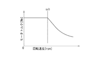
前述のように、モータMはその出力できる限界トルクTc以上の負荷がかけられると脱調し、停止してしまうが、一般に埋込磁石同期モータは、図2に示すようなトルク特性を有している。すなわち、所定の回転速度ωb以下の領域では限界トルクTcは一定で、ωbを越えた領域では限界トルクTcが急速に低下する。電動コンプレッサ1の駆動中は、モータMの出力するトルクTがコンプレッサの負荷となるので、負荷の変動はモータトルクTの変動で知ることができる。したがって、脱調防止のためには、上記の限界トルクTcに達する前に過負荷と判定するように閾値を設定し、当該閾値に達したときにモータMの回転速度を減少させる必要がある。
Next, the setting of the overload determination threshold value Tz will be described in detail.
As described above, the motor M will step out and stop when a load greater than the limit torque Tc that can be output is applied, but an embedded magnet synchronous motor generally has a torque characteristic as shown in FIG. ing. That is, the limit torque Tc is constant in the region below the predetermined rotational speed ωb, and the limit torque Tc rapidly decreases in the region exceeding ωb. While the electric compressor 1 is being driven, the torque T output from the motor M serves as a load on the compressor, so that the fluctuation of the load can be known from the fluctuation of the motor torque T. Therefore, in order to prevent step-out, it is necessary to set a threshold value so as to determine an overload before reaching the limit torque Tc, and to decrease the rotational speed of the motor M when the threshold value is reached.
しかし、モータMの回転速度ωを減少させてもコンプレッサ負荷の反応速度は遅く、負荷は直ちには低下せず、図3に示すように、オーバーシュートする。すなわち、時刻t0で回転速度ωを減少させ始めても、負荷に相当するモータトルクTは逆に増大し、時刻t1に至ってからようやく高トルクの状態から低下していく。
ここで、オーバーシュート量(トルクの増大量および時刻t0時のトルク値に戻るまでの時間)は、回転速度ωを減少させ始めた時刻t0直前のモータトルクTの変動速度(傾斜α)と関連しており、図4に示すように、モータトルクTの変動速度が大きいほどオーバーシュート量も大きいことが判明した。
そこで、本実施の形態では、過負荷判定閾値設定部16は、図2に示したトルク特性に加えてオーバーシュートの特性も踏まえた過負荷判定閾値Tzを設定するものとする。
However, even if the rotational speed ω of the motor M is decreased, the response speed of the compressor load is slow, and the load does not decrease immediately, but overshoots as shown in FIG. In other words, even if the rotational speed ω starts to decrease at time t0, the motor torque T corresponding to the load increases conversely, and finally decreases from the high torque state after reaching time t1.
Here, the amount of overshoot (the amount of increase in torque and the time until the torque value returns to the time t0) is related to the fluctuation speed (inclination α) of the motor torque T just before the time t0 when the rotational speed ω starts to decrease. As shown in FIG. 4, it has been found that the overshoot amount increases as the fluctuation speed of the motor torque T increases.
Therefore, in the present embodiment, the overload determination
このため、過負荷判定閾値設定部は、図5に示す機能構成を有している。
過負荷判定閾値設定部16は、負荷変動算出部20、低速領域マップ22と高速領域マップ24、および速度領域切換スイッチ26を備える。
モータMのトルク特性は先の図2に示したように、限界トルクTcが一定である回転速度ωb以下の領域と、回転速度ωが増すにしたがって限界トルクTcが減少する領域に分かれるので、低速領域マップ22と高速領域マップ24はそれぞれの領域に対応している。
いずれのマップも、オーバーシュートがあってもモータトルクTが限界トルクTcを越えないようにあらかじめ実験などに基づいて設定される。
For this reason, the overload determination threshold value setting unit has a functional configuration shown in FIG.
The overload determination
As shown in FIG. 2, the torque characteristic of the motor M is divided into a region below the rotational speed ωb where the limit torque Tc is constant and a region where the limit torque Tc decreases as the rotational speed ω increases. The
Both maps are set based on experiments in advance so that the motor torque T does not exceed the limit torque Tc even if there is an overshoot.
とくに低速領域マップ22は、図4のモータトルク変動速度に応じたオーバーシュート量によって限界トルクTcを越えることがないように、モータトルクTの変動速度(傾斜α=dT/dt)をパラメータとして閾値Tlが設定されている。
閾値Tlは、モータトルクTの変動速度が低い場合は高く、モータトルクTの変動速度が高くなるほど低くなっている。
負荷変動算出部20はモータトルクTの変動速度dT/dtを求め、過負荷判定閾値設定部16はこの変動速度に基づいて低速領域マップ22から閾値Tlを読み出す。
In particular, the low
The threshold value Tl is high when the fluctuation speed of the motor torque T is low, and is lower as the fluctuation speed of the motor torque T is higher.
The load
一方、高速領域マップ24は、回転速度ωをパラメータとして閾値Thが設定されている。
高速領域での閾値Thは限界トルクTcにほぼ沿っており、限界トルクTcとの差は低速領域マップにおける限界トルクTcと閾値Tlの差より小さくなっている。
過負荷判定閾値設定部16は回転センサ3からの回転速度ωに基づいて高速領域マップ24から閾値Thを読み出す。
速度領域切換スイッチ(速度領域切換SW)26は、回転速度ωb以下のときは低速領域選択状態となり低速領域マップ22から読み出した閾値Tlを過負荷判定閾値Tzとして負荷判定部17へ出力し、回転速度ωbを越えているときは高速領域選択状態となり高速領域マップ24から読み出した閾値Thを過負荷判定閾値Tzとして負荷判定部17へ出力する。
On the other hand, in the high-
The threshold Th in the high speed region is substantially along the limit torque Tc, and the difference from the limit torque Tc is smaller than the difference between the limit torque Tc and the threshold Tl in the low speed region map.
The overload determination
The speed region changeover switch (speed region changeover SW) 26 is in a low speed region selection state when the rotational speed is equal to or lower than ωb, and outputs the threshold value Tl read from the low
つぎに、上記構成になる電動コンプレッサ制御装置の動作について説明する。
図6は電動コンプレッサ制御装置10の制御動作を示すフローチャートであり、電動コンプレッサ1の運転中、一定時間間隔で繰り返される。
まずステップ100において、モータ指令速度生成部11はエアコン設定温度と車室内温度を基にモータ指令速度ωoを生成する。
ステップ101では、モータトルク演算部15において、モータ電流id、iqを基にモータトルクTを算出する。
ステップ102において、過負荷判定閾値設定部16では速度領域切換スイッチ26に回転センサ3からの回転速度ωが読み込まれ、回転速度がωb以下であるかどうかがチェックされる。
回転速度がωb以下であるときはステップ103へ進み、回転速度がωbを越えているときはステップ105へ進む。
Next, the operation of the electric compressor control device configured as described above will be described.
FIG. 6 is a flowchart showing the control operation of the electric
First, at
In
In
When the rotational speed is equal to or less than ωb, the process proceeds to step 103, and when the rotational speed exceeds ωb, the process proceeds to step 105.
ステップ103では、速度領域切換スイッチ26が低速領域選択側に切り換わる。
そしてステップ104において、過負荷判定閾値設定部16では負荷変動算出部20によりモータトルクTの変動速度dT/dtを求めるとともに、この変動速度に基づいて低速領域マップ22から閾値Tlを読み出して過負荷判定閾値Tzとする。この過負荷判定閾値Tzは低速領域選択側に切り換わった速度領域切換スイッチ26から負荷判定部17へ出力される。
In
In
一方、ステップ105では、速度領域切換スイッチ26が高速領域選択側に切り換わる。
そしてステップ106において、回転速度ωに基づいて高速領域マップ24から閾値Thを読み出して過負荷判定閾値Tzとする。この過負荷判定閾値Tzは高速領域選択側に切り換わった速度領域切換スイッチ26から負荷判定部17へ出力される。
On the other hand, in
In
ステップ107において、負荷判定部17はステップ101で算出されたモータトルクTがステップ104または106で設定された過負荷判定閾値Tz以上であるかどうかをチェックする。そして、モータトルクTが過負荷判定閾値Tz以上であるときはモータMが過負荷状態、モータトルクTが過負荷判定閾値Tzに達していないときはモータMは過負荷でない、すなわち安全負荷状態である旨判定して、判定信号を指令速度補正部12へ出力する。
ステップ108において、指令速度補正部12は判定信号により、負荷状態が過負荷であるかどうかをチェックする。
判定信号が過負荷でなく、すなわち安全負荷のときは、ステップ109へ進んで、先のステップ100で生成されたモータ指令速度ωoをそのまま最終指令速度ωtとしてモータ制御部13へ送る。
In
In
When the determination signal is not an overload, that is, a safe load, the routine proceeds to step 109, where the motor command speed ωo generated at the
一方、判定信号が過負荷であるときはステップ110へ進んで、前回モータ制御部13へ送った最終指令速度ωtに対して所定量だけ減少させる補正を施して今回の最終指令速度ωtとしてモータ制御部13へ送る。なお、制御開始の最初のフローにおいて判定信号が過負荷となった場合には、前回モータ制御部へ送った最終指令速度ωtとしてステップ100で生成されたモータ指令速度ωoを用いる。
ステップ111では、モータ制御部13により、モータMの実際の回転速度ωが指令速度補正部12から送られた最終指令速度ωtとなるように、電動コンプレッサ1のインバータInvを駆動して、ステップ100へ戻る。
On the other hand, when the determination signal is overloaded, the routine proceeds to step 110, where the final command speed ωt sent to the previous
In
上述の制御により、モータ回転の低速領域において、モータトルクTの変動速度が高い場合には、図7の(a)に示すように、過負荷判定閾値Tzが低く設定されるため、限界トルクTcまでの余裕が確保されて、モータトルクTがこの過負荷判定閾値Tzに達した時点で回転速度を減少させれば、オーバーシュート量が大きくても限界トルクTcを越えて脱調に至ることなく、いずれモータトルクTすなわち負荷が過負荷判定閾値Tz以下に戻って、電動コンプレッサ1の運転を安定に継続することができる。 With the above control, when the fluctuation speed of the motor torque T is high in the low speed region of the motor rotation, the overload determination threshold Tz is set low as shown in FIG. If the rotational speed is reduced when the motor torque T reaches the overload determination threshold Tz when the motor torque T reaches the overload determination threshold value Tz, even if the overshoot amount is large, the motor does not step out beyond the limit torque Tc. Eventually, the motor torque T, that is, the load returns to the overload determination threshold Tz or less, and the operation of the electric compressor 1 can be continued stably.
また、モータトルクTの変動速度が低い場合には、図7の(b)に示すように、オーバーシュート量が比較的に小さいので、過負荷判定閾値Tzが高くなってもオーバーシュートによって限界トルクTcを越えることはない。そして、過負荷判定閾値Tzが高い分だけ回転速度を減少させる過負荷判定閾値Tzに達するまでの余裕が大きく、広い運転範囲が確保される。 Further, when the fluctuation speed of the motor torque T is low, as shown in FIG. 7B, the overshoot amount is relatively small. Therefore, even if the overload determination threshold Tz becomes high, the limit torque is caused by overshoot. It does not exceed Tc. And the allowance until it reaches the overload determination threshold value Tz that decreases the rotational speed by the amount that the overload determination threshold value Tz is high is large, and a wide operation range is secured.
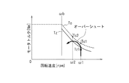
一方、モータ回転の高速領域においては、先の図2に示したように、回転速度ωが高くなるほど限界トルクTcが低下し、換言すれば回転速度ωが減少すると限界トルクTcが増大する。
このため、図8に示すように、回転速度ω1の時点(限界トルクTc1)でモータトルクTが過負荷判定閾値Tz1に達して回転速度を減少させると、オーバーシュートは発生するが、低い値に減少した回転速度ω2における限界トルクTc2がTc1よりも高い値へ増大しているので、過負荷判定閾値TzがモータトルクTの変動速度に係わらず限界トルクTcに近い値に設定してあっても、オーバーシュートによって限界トルクTcを越えることはない。したがって、高速領域においては過負荷判定閾値Tzが高い分だけ広い運転範囲が確保されることになる。
On the other hand, in the high speed region of motor rotation, as shown in FIG. 2, the limit torque Tc decreases as the rotation speed ω increases. In other words, the limit torque Tc increases as the rotation speed ω decreases.
Therefore, as shown in FIG. 8, when the motor torque T reaches the overload determination threshold value Tz1 at the time of the rotational speed ω1 (limit torque Tc1) and the rotational speed is decreased, overshoot occurs, but the value becomes low. Since the limit torque Tc2 at the reduced rotational speed ω2 increases to a value higher than Tc1, the overload determination threshold Tz may be set to a value close to the limit torque Tc regardless of the fluctuation speed of the motor torque T. The limit torque Tc is not exceeded by overshoot. Therefore, in the high speed region, a wider operation range is ensured as the overload determination threshold Tz is higher.
本実施の形態においては、回転センサ3が発明における回転速度検出手段に該当し、過負荷判定閾値設定部16が閾値設定手段に、過負荷判定閾値Tzが閾値にそれぞれ該当する。
In the present embodiment, the rotation sensor 3 corresponds to the rotation speed detection means in the invention, the overload determination
実施の形態は以上のように構成され、モータ指令速度ωoを生成するモータ指令速度生成部11と、モータトルクTを算出するモータトルク演算部15と、モータの回転速度ωを検出する回転センサ3と、モータの回転速度に応じて、電動コンプレッサ1の過負荷判定閾値Tzを設定する過負荷判定閾値設定部16と、モータトルクTを過負荷判定閾値Tzと比較して電動コンプレッサ1の負荷状態を判定する負荷判定部17と、電動コンプレッサ1の負荷状態に応じてモータ指令速度ωoを補正し、最終指令速度ωtを出力する指令速度補正部12と、最終指令速度ωtに基づいて電動コンプレッサのモータMを駆動するモータ制御部13とを有し、指令速度補正部12は、負荷判定部17における判定が過負荷であるとき、モータ指令速度ωoを減少させて最終指令速度ωtとし、負荷判定部17における判定が過負荷でないときはモータ指令速度ωoをそのまま最終指令速度ωtとするものとした。
これにより、電動コンプレッサ1の過負荷の判定基準である過負荷判定閾値TzがモータMの回転速度ωに応じて可変に設定されるので、負荷に対応するモータのトルク特性に合わせて、脱調を招く限界トルクTcに対して必要な余裕代だけ手前で回転速度を減少させればよく、脱調防止とともに、電動コンプレッサ1の運転範囲を拡大することができるので、モータの小型化、軽量化にもつながる。
The embodiment is configured as described above, and includes a motor command
As a result, the overload determination threshold value Tz, which is the determination criterion for the overload of the electric compressor 1, is variably set according to the rotational speed ω of the motor M. It is sufficient to reduce the rotational speed just before the necessary margin with respect to the limit torque Tc that causes the motor, and the operation range of the electric compressor 1 can be expanded while preventing the step-out, so the motor is reduced in size and weight. It also leads to.
過負荷判定閾値設定部16は、モータの回転速度ωが所定値ωb以下の低速領域では、過負荷判定閾値TzをモータトルクTの変動速度に応じて変化させ、モータの回転速度ωが所定値ωbを越える高速領域では、過負荷判定閾値TzをモータトルクTの変動速度と無関係にモータの回転速度ωに基づいて設定するものとし、低速領域において変動速度によるモータトルクTのオーバーシュート量の変化に対応した脱調防止ができる。
とくに、モータトルクTの変動速度が小さいときは過負荷判定閾値Tzを高く、変動速度が大きくなるほど過負荷判定閾値Tzを低くすることにより、変動速度が小さいときは運転範囲が拡大する。
The overload determination
In particular, the overload determination threshold Tz is increased when the fluctuation speed of the motor torque T is small, and the overload determination threshold Tz is decreased as the fluctuation speed increases, so that the operating range is expanded when the fluctuation speed is small.
また、上記の所定値ωbが、モータの限界トルクTcが一定の状態からモータの回転速度ωに応じて変化し始める回転速度であるため、高速領域における過負荷判定閾値Tzとモータの限界トルクTcの差を、低速領域における過負荷判定閾値Tzと限界トルクTcの差よりも小さくなっているにもかかわらず、トルク特性によって回転速度減少後は限界トルクTcが高くなるので、オーバーシュートによって脱調に至ることはなく、運転範囲が拡大する。 Further, since the predetermined value ωb is a rotational speed at which the motor limit torque Tc starts to change in accordance with the motor rotational speed ω from a constant state, the overload determination threshold Tz in the high speed region and the motor limit torque Tc Although the difference in torque is smaller than the difference between the overload determination threshold value Tz and the limit torque Tc in the low speed region, the limit torque Tc increases after the rotational speed decreases due to the torque characteristics. The operating range is expanded.
なお、実施の形態において、閾値設定手段としての過負荷判定閾値設定部16は、閾値Tl、Thを低速マップ22および高速領域マップ24から読み出して速度領域切換スイッチ26を介して過負荷判定閾値Tzとして出力するものとしたが、これに限定されず、例えばマップの代わり関数を設定して演算により過負荷判定閾値Tzを求めるようにしてもよい。
また、回転速度検出手段として回転センサ3を備える例を示したが、回転センサを用いる代わりに、速度センサレス制御によってもよい。
In the embodiment, the overload determination
Moreover, although the example provided with the rotation sensor 3 as a rotation speed detection means was shown, instead of using a rotation sensor, you may perform speed sensorless control.
本発明は、車両の空調装置その他に用いられて、安定した運転が要求される電動コンプレッサの制御装置としてとくに有用である。 INDUSTRIAL APPLICABILITY The present invention is particularly useful as a control device for an electric compressor that is used in a vehicle air conditioner or the like and requires stable operation.
1 電動コンプレッサ
2 電流検出部
3 回転センサ
4 室内温度センサ
5 温度設定部
10 電動コンプレッサ制御装置
11 モータ指令速度生成部
12 指令速度補正部
13 モータ制御部
15 モータトルク演算部
16 過負荷判定閾値設定部
17 負荷判定部
20 負荷変動算出部
22 低速領域マップ
24 高速領域マップ
26 速度領域切換スイッチ
Comp コンプレッサ本体
Inv インバータ
M モータ
DESCRIPTION OF SYMBOLS 1 Electric compressor 2 Current detection part 3
Claims (3)
モータが出力するモータトルクを算出するモータトルク演算部(15)と、
モータの回転速度を検出する回転速度検出手段(3)と、
モータの回転速度に応じて、電動コンプレッサの過負荷判定基準とする閾値を設定する閾値設定手段(16)と、
前記モータトルクを前記閾値と比較して電動コンプレッサの負荷状態を判定する負荷判定部(17)と、
電動コンプレッサ(1)の負荷状態に応じてモータ指令速度を補正し、最終指令速度を出力する指令速度補正部(12)と、
最終指令速度に基づいて電動コンプレッサのモータを駆動するモータ制御部(13)と、を有し、
前記指令速度補正部は、
負荷判定部における判定が過負荷であるとき、モータ指令速度を減少させて最終指令速度とし、
負荷判定部における判定が過負荷でないときはモータ指令速度をそのまま最終指令速度とし、
前記閾値設定手段(16)は、
モータの回転速度が所定値以下の領域では、前記閾値を前記モータトルクの変動速度に応じて変化させ、前記閾値は、前記モータトルクの変動速度が小さいときは高く、変動速度が大きくなるほど低いことを特徴とする電動コンプレッサ制御装置。 A motor command speed generator (11) for generating a motor command speed;
A motor torque calculator (15) for calculating a motor torque output by the motor;
Rotational speed detection means (3) for detecting the rotational speed of the motor;
Threshold setting means (16) for setting a threshold value as an overload determination criterion for the electric compressor according to the rotational speed of the motor;
A load determination unit (17) for determining the load state of the electric compressor by comparing the motor torque with the threshold;
A command speed correction unit (12) for correcting the motor command speed in accordance with the load state of the electric compressor (1) and outputting a final command speed;
A motor control unit (13) for driving the motor of the electric compressor based on the final command speed,
The command speed correction unit is
When the determination in the load determination unit is overload, the motor command speed is reduced to the final command speed,
When the determination in the load determination unit is not overload, the motor command speed is used as the final command speed as it is
The threshold setting means (16)
In a region where the rotational speed of the motor is less than or equal to a predetermined value, the threshold value is changed according to the fluctuation speed of the motor torque, and the threshold value is high when the fluctuation speed of the motor torque is small, and lower as the fluctuation speed increases. An electric compressor control device characterized by the above.
モータの回転速度が前記所定値を越える領域では、前記閾値を前記モータトルクの変動速度と無関係にモータの回転速度に基づいて設定するものであることを特徴とする請求項1に記載の電動コンプレッサ制御装置。 Said threshold setting means (16),
In the region where the rotational speed of the motors exceeds a predetermined value, according to claim 1, characterized in that the set based on the threshold value to the rotation speed of the motor independently of the changing speed of the motor torque Electric compressor control device.
始める回転速度であり、
前記閾値はモータの限界トルクより低く設定され、
前記高速領域における前記閾値と限界トルクの差は、前記低速領域における前記閾値と
限界トルクの差よりも小さいことを特徴とする請求項1または2に記載の電動コンプレッ
サ制御装置。 The predetermined value varies depending on the rotational speed of the motor from a state where the limit torque of the motor is constant.
Starting rotational speed,
The threshold is set lower than the motor limit torque,
The difference between the threshold value in the high speed region and the limit torque is the threshold value in the low speed region.
The electric compressor control device according to claim 1 , wherein the electric compressor control device is smaller than a difference in limit torque .
Priority Applications (1)
| Application Number | Priority Date | Filing Date | Title |
|---|---|---|---|
| JP2009027269A JP5344946B2 (en) | 2009-02-09 | 2009-02-09 | Electric compressor control device |
Applications Claiming Priority (1)
| Application Number | Priority Date | Filing Date | Title |
|---|---|---|---|
| JP2009027269A JP5344946B2 (en) | 2009-02-09 | 2009-02-09 | Electric compressor control device |
Publications (2)
| Publication Number | Publication Date |
|---|---|
| JP2010183796A JP2010183796A (en) | 2010-08-19 |
| JP5344946B2 true JP5344946B2 (en) | 2013-11-20 |
Family
ID=42764863
Family Applications (1)
| Application Number | Title | Priority Date | Filing Date |
|---|---|---|---|
| JP2009027269A Expired - Fee Related JP5344946B2 (en) | 2009-02-09 | 2009-02-09 | Electric compressor control device |
Country Status (1)
| Country | Link |
|---|---|
| JP (1) | JP5344946B2 (en) |
Cited By (1)
| Publication number | Priority date | Publication date | Assignee | Title |
|---|---|---|---|---|
| WO2021115076A1 (en) * | 2019-12-13 | 2021-06-17 | 中国科学院深圳先进技术研究院 | Motor function safety control method and device |
Families Citing this family (3)
| Publication number | Priority date | Publication date | Assignee | Title |
|---|---|---|---|---|
| JP2015116024A (en) * | 2013-12-11 | 2015-06-22 | カルソニックカンセイ株式会社 | Control device for electric compressor |
| US10033308B2 (en) * | 2015-03-17 | 2018-07-24 | Intuitive Surgical Operations, Inc. | Systems and methods for motor torque compensation |
| CN110574284B (en) * | 2017-04-28 | 2023-06-20 | 日本电产株式会社 | Motor driving device, motor driving method, recording medium, and engine cooling device |
Family Cites Families (5)
| Publication number | Priority date | Publication date | Assignee | Title |
|---|---|---|---|---|
| JPH02214489A (en) * | 1989-02-10 | 1990-08-27 | Nippon Electric Ind Co Ltd | Overload protecting circuit for induction motor |
| JP2836884B2 (en) * | 1990-01-23 | 1998-12-14 | 株式会社日立製作所 | Inverter device |
| JPH09294396A (en) * | 1996-04-24 | 1997-11-11 | Shinko Electric Co Ltd | Speed controller |
| JP4720619B2 (en) * | 2006-05-30 | 2011-07-13 | 株式会社明電舎 | Variable speed drive device for motor |
| JP5235390B2 (en) * | 2007-11-27 | 2013-07-10 | 三菱電機株式会社 | Inverter control device and air conditioner |
-
2009
- 2009-02-09 JP JP2009027269A patent/JP5344946B2/en not_active Expired - Fee Related
Cited By (1)
| Publication number | Priority date | Publication date | Assignee | Title |
|---|---|---|---|---|
| WO2021115076A1 (en) * | 2019-12-13 | 2021-06-17 | 中国科学院深圳先进技术研究院 | Motor function safety control method and device |
Also Published As
| Publication number | Publication date |
|---|---|
| JP2010183796A (en) | 2010-08-19 |
Similar Documents
| Publication | Publication Date | Title |
|---|---|---|
| JP4259173B2 (en) | Electric compressor drive device | |
| JP3506457B2 (en) | Startup control method of compressor in air conditioner | |
| KR101392953B1 (en) | Motor drive device, air conditioner comprising motor drive device, and motor drive method | |
| JP5628233B2 (en) | Motor drive device, fluid compression system, and air conditioner | |
| KR101550751B1 (en) | Motor control device, motor drive device using the same, compressor, refrigeration device, air conditioner, and motor control method | |
| US10458420B2 (en) | Method for controlling motor-driven compressor configured to be installed in vehicle | |
| US20100114379A1 (en) | Fan control system | |
| JP4300730B2 (en) | Permanent magnet motor device, refrigeration cycle device, and driving method of permanent magnet motor | |
| JP2010022111A (en) | Refrigerator | |
| JP5344946B2 (en) | Electric compressor control device | |
| JP3622666B2 (en) | Synchronous motor control method and apparatus | |
| JP4804100B2 (en) | Motor drive device, control method therefor, and air conditioner | |
| JP2009236445A (en) | Refrigeration apparatus | |
| JP7023387B2 (en) | Motor control device and air conditioner | |
| JP5752546B2 (en) | Motor control device, compressor and heat pump device | |
| JP2005204383A (en) | Method of controlling brushless dc motor | |
| JP7044523B2 (en) | Motor control device and electric compressor equipped with it, air conditioner for moving body, motor control method and motor control program | |
| JP2018148678A (en) | Motor controller and air conditioner | |
| JP2005207362A (en) | Driving device for electric compressor | |
| JP2014187802A (en) | Motor drive device | |
| JP6410939B2 (en) | Motor control device, compressor, and air conditioner | |
| JP4131318B2 (en) | Air conditioner | |
| JP6093606B2 (en) | Motor drive device | |
| EP3355466A1 (en) | Motor control device, rotary compressor system and motor control method | |
| WO2023176279A1 (en) | Electric compressor |
Legal Events
| Date | Code | Title | Description |
|---|---|---|---|
| A621 | Written request for application examination |
Free format text: JAPANESE INTERMEDIATE CODE: A621 Effective date: 20110831 |
|
| A977 | Report on retrieval |
Free format text: JAPANESE INTERMEDIATE CODE: A971007 Effective date: 20130307 |
|
| A131 | Notification of reasons for refusal |
Free format text: JAPANESE INTERMEDIATE CODE: A131 Effective date: 20130312 |
|
| A521 | Written amendment |
Free format text: JAPANESE INTERMEDIATE CODE: A523 Effective date: 20130513 |
|
| TRDD | Decision of grant or rejection written | ||
| A01 | Written decision to grant a patent or to grant a registration (utility model) |
Free format text: JAPANESE INTERMEDIATE CODE: A01 Effective date: 20130813 |
|
| A61 | First payment of annual fees (during grant procedure) |
Free format text: JAPANESE INTERMEDIATE CODE: A61 Effective date: 20130813 |
|
| R150 | Certificate of patent or registration of utility model |
Ref document number: 5344946 Country of ref document: JP Free format text: JAPANESE INTERMEDIATE CODE: R150 Free format text: JAPANESE INTERMEDIATE CODE: R150 |
|
| R250 | Receipt of annual fees |
Free format text: JAPANESE INTERMEDIATE CODE: R250 |
|
| R250 | Receipt of annual fees |
Free format text: JAPANESE INTERMEDIATE CODE: R250 |
|
| R250 | Receipt of annual fees |
Free format text: JAPANESE INTERMEDIATE CODE: R250 |
|
| R250 | Receipt of annual fees |
Free format text: JAPANESE INTERMEDIATE CODE: R250 |
|
| LAPS | Cancellation because of no payment of annual fees |