JP6410939B2 - Motor control device, compressor, and air conditioner - Google Patents
Motor control device, compressor, and air conditioner Download PDFInfo
- Publication number
- JP6410939B2 JP6410939B2 JP2017528018A JP2017528018A JP6410939B2 JP 6410939 B2 JP6410939 B2 JP 6410939B2 JP 2017528018 A JP2017528018 A JP 2017528018A JP 2017528018 A JP2017528018 A JP 2017528018A JP 6410939 B2 JP6410939 B2 JP 6410939B2
- Authority
- JP
- Japan
- Prior art keywords
- motor
- current
- load torque
- value
- calculating
- Prior art date
- Legal status (The legal status is an assumption and is not a legal conclusion. Google has not performed a legal analysis and makes no representation as to the accuracy of the status listed.)
- Active
Links
Images


Classifications
-
- H—ELECTRICITY
- H02—GENERATION; CONVERSION OR DISTRIBUTION OF ELECTRIC POWER
- H02P—CONTROL OR REGULATION OF ELECTRIC MOTORS, ELECTRIC GENERATORS OR DYNAMO-ELECTRIC CONVERTERS; CONTROLLING TRANSFORMERS, REACTORS OR CHOKE COILS
- H02P6/00—Arrangements for controlling synchronous motors or other dynamo-electric motors using electronic commutation dependent on the rotor position; Electronic commutators therefor
- H02P6/28—Arrangements for controlling current
-
- H—ELECTRICITY
- H02—GENERATION; CONVERSION OR DISTRIBUTION OF ELECTRIC POWER
- H02P—CONTROL OR REGULATION OF ELECTRIC MOTORS, ELECTRIC GENERATORS OR DYNAMO-ELECTRIC CONVERTERS; CONTROLLING TRANSFORMERS, REACTORS OR CHOKE COILS
- H02P6/00—Arrangements for controlling synchronous motors or other dynamo-electric motors using electronic commutation dependent on the rotor position; Electronic commutators therefor
- H02P6/14—Electronic commutators
- H02P6/15—Controlling commutation time
-
- H—ELECTRICITY
- H02—GENERATION; CONVERSION OR DISTRIBUTION OF ELECTRIC POWER
- H02P—CONTROL OR REGULATION OF ELECTRIC MOTORS, ELECTRIC GENERATORS OR DYNAMO-ELECTRIC CONVERTERS; CONTROLLING TRANSFORMERS, REACTORS OR CHOKE COILS
- H02P23/00—Arrangements or methods for the control of AC motors characterised by a control method other than vector control
- H02P23/26—Power factor control [PFC]
-
- H—ELECTRICITY
- H02—GENERATION; CONVERSION OR DISTRIBUTION OF ELECTRIC POWER
- H02P—CONTROL OR REGULATION OF ELECTRIC MOTORS, ELECTRIC GENERATORS OR DYNAMO-ELECTRIC CONVERTERS; CONTROLLING TRANSFORMERS, REACTORS OR CHOKE COILS
- H02P29/00—Arrangements for regulating or controlling electric motors, appropriate for both AC and DC motors
- H02P29/02—Providing protection against overload without automatic interruption of supply
- H02P29/024—Detecting a fault condition, e.g. short circuit, locked rotor, open circuit or loss of load
- H02P29/0241—Detecting a fault condition, e.g. short circuit, locked rotor, open circuit or loss of load the fault being an overvoltage
Description
本発明は、各種モータの駆動を制御する機能を備えたモータ制御装置、圧縮機、及び空気調和機に関するものである。 The present invention relates to a motor control device, a compressor, and an air conditioner having a function of controlling driving of various motors.
従来から、空気調和機等に設けられる圧縮機のモータを可変速制御するために、整流回路から出力される直流電圧を所定の周期でオン・オフして交流電圧に変換するインバータ回路を備えた空気調和機があった。空気調和機を構成する圧縮機のモータは、高効率化が重視されるため、圧縮機のモータとしては、回転子構造に希土類永久磁石を内部に配置したモータ(以下、永久磁石同期モータと称する)が用いられることが多い。 Conventionally, in order to perform variable speed control of a compressor motor provided in an air conditioner or the like, an inverter circuit that turns on and off a DC voltage output from a rectifier circuit at a predetermined cycle is provided. There was an air conditioner. Since the motor of the compressor constituting the air conditioner is focused on high efficiency, the compressor motor is a motor having a rare earth permanent magnet arranged in a rotor structure (hereinafter referred to as a permanent magnet synchronous motor). ) Is often used.
ここで従来、回転子の永久磁石の磁極位置を位置センサ等によって検出し、電流を検出した磁極位相に基づいて、永久磁石同期モータの回転数を制御する方式が提案されている。また従来、磁束センサを用いないで永久磁石同期モータの回転数を制御する方式(以後、位置センサレス制御と称する)等が提案されている(例えば特許文献1)。特許文献1に記載の位置センサレス制御は、例えば、空気調和機の圧縮機の内部が高温且つ高圧状態であるために圧縮機の内部に磁束センサを設置することができないような場合に適用される。
Heretofore, a method has been proposed in which the magnetic pole position of the permanent magnet of the rotor is detected by a position sensor or the like, and the rotational speed of the permanent magnet synchronous motor is controlled based on the magnetic pole phase from which the current is detected. Conventionally, a method of controlling the rotation speed of a permanent magnet synchronous motor without using a magnetic flux sensor (hereinafter referred to as position sensorless control) has been proposed (for example, Patent Document 1). The position sensorless control described in
しかしながら、従来の空気調和機においては、圧縮機が液冷媒を吸入した場合、モータの負荷トルクが急激に変動してモータが出力可能なトルクを超え、同期はずれ(以下、脱調と称する)という現象が発生して機器が異常停止するという課題があった。 However, in a conventional air conditioner, when the compressor sucks liquid refrigerant, the load torque of the motor suddenly fluctuates and exceeds the torque that can be output by the motor, and is out of synchronization (hereinafter referred to as step-out). There was a problem that the phenomenon occurred and the equipment stopped abnormally.
また、特許文献1に記載の位置センサレス制御方式を用いて、モータを制御する場合、回転子の磁極位置を直接検出していないために脱調が生じやすいという課題があった。なお、通常、液冷媒はアキュームレータに溜まるため、圧縮機が液冷媒を吸入することはないが、室外機熱交換器の霜取運転時等において、液冷媒が、アキュームレータに溜められる液冷媒の許容値を超えてアキュームレータに導入されると、圧縮機が液冷媒を吸入することで負荷トルクが急変してモータが脱調する場合がある。
Further, when the motor is controlled using the position sensorless control method described in
本発明は、上述のような課題を背景としてなされたものであり、モータの負荷トルクが増加した場合における脱調を回避して運転を継続させることができるモータ制御装置、圧縮機、及び空気調和機を得ることを目的としている。 The present invention has been made against the background of the above-described problems. A motor control device, a compressor, and an air conditioner that can continue operation while avoiding step-out when the load torque of the motor increases. The purpose is to get a chance.
本発明に係るモータ制御装置は、モータを制御するモータ制御装置であって、前記モータの負荷トルクを検知する負荷トルク検知手段と、前記負荷トルク検知手段が検知した前記負荷トルクが増加するほど前記モータに流れる電流を増加させる電流補正手段と、を有し、前記負荷トルク検知手段は、前記モータの力率を算出する力率算出手段を備え、前記電流補正手段は、前記力率算出手段によって算出される前記モータの力率が第2基準値以下である場合に、前記負荷トルクが増加したものとして前記モータに流れる電流を増加させるものである。 The motor control device according to the present invention is a motor control device for controlling a motor, wherein the load torque detection means for detecting the load torque of the motor, and the load torque detected by the load torque detection means increases as the load torque increases. Current correction means for increasing the current flowing through the motor, wherein the load torque detection means includes power factor calculation means for calculating a power factor of the motor, and the current correction means is controlled by the power factor calculation means. When the calculated power factor of the motor is equal to or less than a second reference value , the current flowing through the motor is increased as the load torque is increased .
本発明に係る圧縮機は、本発明のモータ制御装置によって制御される前記モータを備えたものである。 The compressor which concerns on this invention is provided with the said motor controlled by the motor control apparatus of this invention.
本発明に係る空気調和機は、本発明の圧縮機と、前記モータの電流を検出する電流検出手段と、前記電流検出手段によって検出される電流値が電流基準値以上である場合に前記モータ制御装置を停止させる過電流保護手段と、を備えたものである。 The air conditioner according to the present invention includes the compressor according to the present invention, current detection means for detecting a current of the motor, and the motor control when a current value detected by the current detection means is equal to or greater than a current reference value. And overcurrent protection means for stopping the apparatus.
本発明によれば、電流補正手段は、負荷トルク検知手段が検知した負荷トルクが増加するほどモータに流れる電流を増加させるため、モータの負荷トルクが増加した場合における脱調を回避して運転を継続させることができる。 According to the present invention, the current correction means increases the current flowing through the motor as the load torque detected by the load torque detection means increases. Therefore, the current correction means avoids the step-out when the motor load torque increases. Can continue.
以下、本発明を実施するための形態について、図面を参照して説明する。ここで、図1を含む以下の図面において、同一の符号を付したものは、同一又はこれに相当するものであり、以下に記載する実施の形態の全文において共通することとする。そして、明細書全文に表わされている構成要素の形態は、あくまでも例示であって、明細書に記載された形態に限定するものではない。 Hereinafter, embodiments for carrying out the present invention will be described with reference to the drawings. Here, in the following drawings including FIG. 1, the same reference numerals denote the same or corresponding parts, and are common to all the embodiments described below. And the form of the component represented by the whole specification is an illustration to the last, Comprising: It does not limit to the form described in the specification.
実施の形態1.
図1は本発明の実施の形態1に係る空気調和機100及びモータ制御装置200の回路構成及び制御ブロック図を示す概念図である。図2は本発明の実施の形態1に係るモータ制御装置200の磁束ベクトル制御を構成するベクトル図である。
FIG. 1 is a conceptual diagram showing a circuit configuration and a control block diagram of an
図1に示されるように、空気調和機100は、平滑コンデンサ10と、インバータ回路11と、電流検出手段13と、ゲート駆動回路14と、過電流保護手段15と、モータ30を有する圧縮機29と、凝縮器31と、減圧装置32と、蒸発器33と、を備える。空気調和機100は、交流電源の電圧をダイオードブリッジ回路等によって交流電力から直流電力へとAC−DC変換することでインバータ回路11への直流の入力電圧を得る。
As shown in FIG. 1, an
平滑コンデンサ10は、整流された際の電圧の脈動を平滑化するものである。インバータ回路11は、平滑コンデンサ10により平滑された直流電圧を交流電圧に変換してモータ30を駆動するものである。インバータ回路11は、IGBT(Insulated Gate Bipolar Transistor)等の半導体により構成されたスイッチング素子12と、スイッチング素子12がオフされた場合において逆向きの電流(還流電流)を流すための還流用ダイオード素子と、をそれぞれ6個ずつ備える。インバータ回路11のスイッチング素子12は、例えば、炭化珪素素子、窒化ガリウム系の素子、又はダイヤモンド素子によって構成される。インバータ回路11の出力配線はモータ30に接続されており、インバータ回路11の出力配線には電流検出手段13が設けられている。
The smoothing
電流検出手段13は、例えば、モータ30に流れる三相電流の全相を検出し、インバータ回路11の出力配線を流れる電流に応じた電圧又は電流信号を出力するものである。電流検出手段13は、例えば、モータ30の電流を検出する電流センサ等で構成されている。電流検出手段13が検出したモータ30の電流瞬時値は、マイクロコンピュータ等においてデジタル変換されて内部に取り込まれる。
The
なお、電流検出手段13は、モータ30に流れる2相電流を検出し、検出した2相電流の瞬時値を加算して加算したものを−1倍して残りの1相電流を算出してもよい。また、電流検出手段13は、一般的にホール素子等が内蔵されているものであれば、流れる電流に応じた磁束を検知して電圧に変換するといったものでもよい。
The current detection means 13 detects the two-phase current flowing through the
過電流保護手段15は、電流検出手段13によって検出された電流値が予め定められた電流基準値を超えた場合に空気調和機100の動作を一旦停止させるものであり、インバータ回路11を保護する機能を有する。モータ30が永久磁石同期モータで構成される場合には、固定子巻線に一定以上の電流が流れた場合に回転子の永久磁石磁束を弱める減磁と呼ばれる現象が発生する。また、モータ30が永久磁石同期モータで構成される場合には、固定子巻線に一定以上の電流が流れた場合にインバータ回路11のIGBTでの損失が大きくなる。
The
そこで、上記電流基準値は、例えば、上述した減磁と呼ばれる現象を抑制する観点でモータ30の減磁レベルに応じて決定される。また、上記電流基準値は、例えば、インバータ回路11のIGBTでの損失が大きくなることを抑制する観点で決定される。過電流保護手段15は、例えば、上述の2つの電流基準値のうち小さい方を超えた場合に、空気調和機100の動作を一旦停止させる。
Therefore, the current reference value is determined according to the demagnetization level of the
なお、過電流保護手段15は、電子回路等によってハードウェア的に構成するか、又はマイクロコンピュータ等に電流検出信号を入力してデジタル変換処理を行ってソフトウェア的に保護する手段で構成される。過電流保護手段15が、ソフトウェアによる過電流保護手段15で構成される場合には、自由に閾値を変更でき、また様々な演算処理を実施することができるため、設計の自由度が広がる。 The overcurrent protection means 15 is configured by hardware such as an electronic circuit or the like, or is configured by software by inputting a current detection signal into a microcomputer or the like and performing digital conversion processing. When the overcurrent protection means 15 is configured by software overcurrent protection means 15, the threshold value can be freely changed and various arithmetic processes can be performed, so that the degree of freedom in design is expanded.
圧縮機29は、吸入された冷媒を圧縮して高温及び高圧の冷媒として吐出する、可変容量の圧縮機である。圧縮機29はモータ30を備えている。モータ30は、例えば、省エネ性が高い回転子に永久磁石を用いた構造を有するモータ(永久磁石同期モータ)で構成される。凝縮器31は、圧縮機29から吐出された冷媒を凝縮液化する熱交換器である。
The
減圧装置32は、凝縮器31において凝縮液化された冷媒を減圧膨張するものである。蒸発器33は、減圧装置32から流出した冷媒を蒸発ガス化するものである。圧縮機29と、凝縮器31と、減圧装置32と、蒸発器33と、が各々冷媒配管によって順次接続されることで冷凍サイクル装置が構成される。
The
図1に示されるように、モータ制御装置200は、座標変換手段20と、回転数指令生成手段21と、積分手段22と、γ軸電流指令テーブル23と、周波数補償手段24と、電圧指令演算手段25と、負荷トルク検知手段26と、電流補正手段27と、逆座標変換手段28と、を備える。
As shown in FIG. 1, the
モータ制御装置200は、電流検出手段13が検出した電流値に基づいてモータ30を所望の回転数で制御するようにゲート駆動回路14を制御する。ゲート駆動回路14から出力される信号に基づいてIGBTのゲート―エミッタ端子間に電圧が印可されると、IGBTのコレクタ―エミッタ間が導通してモータ30に対して電圧が印可される。
The
モータ制御装置200は、例えば、モータ30が永久磁石同期モータで構成される場合に、磁束センサ等を用いて永久磁石の磁極位相を検出し、当該磁極位相に基づいて電流を制御する。しかしながら、モータ30のように内部が高温及び高圧状態になるような環境下において磁束センサを設置することは容易ではないため、空気調和機100は、位置センサを用いない位置センサレス制御を行うことが多い。本実施の形態1においては、永久磁石同期モータの位置センサレス制御方式の一例として、モータで生じる一次磁束を定められた軸上に一定に保つように出力電圧を制御する磁束ベクトル制御方式について以下説明する。
For example, when the
座標変換手段20は、モータ回転速度に同期した位相θに基づいて、電流検出手段13によって検出したモータ30に流れる三相交流電流を直流電流に変換するものである。座標変換手段20は、位相θに基づいて、モータ30で発生する磁束を生成する励磁成分電流Iγと、励磁成分電流Iγに直交しモータ30のトルク成分に寄与するトルク成分電流Iδと、を出力する。図2に示されるように、モータ30の永久磁石磁束方向をd軸とし、d軸に対して直交する軸をq軸とすると、本磁束ベクトル制御で用いるγ―δ軸はd−q軸に対してΔθだけずれた位置に制御軸を生成して動作している。
The coordinate conversion means 20 converts the three-phase alternating current flowing in the
回転数指令生成手段21は、空気調和機100が所望の冷凍能力を得るようにモータ30の回転数の指令値を演算する。また、回転数指令生成手段21は、より冷凍能力を必要とするような状態、例えば高温度の外気状態での冷房運転時等において、モータ30の回転数が大きくなるように演算する。回転数指令生成手段21は、例えば、マイクロコンピュータ等によって構成されている。なお、回転数指令生成手段21は、モータ30の回転数だけでなく、ファンモータ回転数、減圧装置32の絞り開度等各アクチュエータを制御するようにしてもよい。
The rotational speed command generating means 21 calculates a rotational speed command value of the
以下に、座標変換に用いるγ―δ軸で回転する位相θを得る手段について説明する。 Hereinafter, a means for obtaining the phase θ rotating around the γ-δ axis used for coordinate conversion will be described.
式(1)で示すように、モータの回転数は、モータに印可される正弦波電圧の周波数fに比例して変化することが知られている。
[数1]
N[min−1] = 120×f/p ・・・(1)As shown by the equation (1), it is known that the rotational speed of the motor changes in proportion to the frequency f of the sine wave voltage applied to the motor.
[Equation 1]
N [min −1 ] = 120 × f / p (1)
ここで、Nは1分間あたりのモータの回転数を表しており、単位は[min−1]である。fはモータに印可される電圧周波数、すなわち本実施の形態1であればインバータ回路11によって発生する3相交流電圧の周波数[Hz]である。pはモータ30の磁極の数(以下、極数と称する)である。Here, N represents the number of rotations of the motor per minute, and its unit is [min −1 ]. f is the voltage frequency applied to the motor, that is, the frequency [Hz] of the three-phase AC voltage generated by the
式(1)で示されるように、モータの回転数はインバータ出力電圧の周波数に比例し、モータの回転数は極数に反比例する関係となる。このことから、インバータ出力電圧の周波数を制御することでモータの回転数が制御できることが分かる。モータ制御装置200は、回転数指令生成手段21が生成した回転数の指令値に対し、比例した電圧周波数を発生させるようにインバータ回路11を制御する。
As shown in the equation (1), the rotational speed of the motor is proportional to the frequency of the inverter output voltage, and the rotational speed of the motor is inversely proportional to the number of poles. From this, it can be seen that the rotational speed of the motor can be controlled by controlling the frequency of the inverter output voltage. The
ここで、磁束ベクトル制御の特徴の一つとして、上述した回転数指令生成手段21の指令値から演算される電気角速度を時間積分することでモータ30の回転数と同期した位相θが得られることが挙げられる。そして、本実施の形態1では、後述する周波数補償手段24を用いることで、さらに安定にモータ30を回転できるよう最終的な位相θを得ることができる。
Here, as one of the features of the magnetic flux vector control, the phase θ synchronized with the rotational speed of the
次に周波数補償手段24の詳細な動作について説明する。周波数補償手段24は前述した回転数指令値に対して、負荷トルク変動時においても安定に位相追従できるように角速度ωを補償する役割を担う。 Next, the detailed operation of the frequency compensation means 24 will be described. The frequency compensation means 24 plays a role of compensating the angular velocity ω so that the phase can be stably followed even when the load torque fluctuates with respect to the above-described rotation speed command value.
例えば、圧縮機29の吐出圧力が高くなってモータ30の負荷トルクが増加した場合には、前述したトルク成分電流Iδも同様に増加する一方、瞬時的にみれば実際のモータ30の磁極位相が遅れ位相となる。このとき、周波数補償手段24は、制御軸であるγ―δ軸を実際の磁極位置に合わせて遅れ位相となるように、トルク成分電流Iδに比例した値を用いて負帰還動作させ周波数を補償するように動作させる。これにより、磁極位置を見失うことなく脱調を回避でき、モータ30を安定に回転させることができる。
For example, when the discharge pressure of the
また例えば、圧縮機29の吐出圧力が低くなってモータ30の負荷トルクが低下した場合には、モータ30の磁極位置が進み位相となる。このとき、周波数補償量も低減することから、γ−δ軸上で制御しているモータ30の一次磁束Φも進み位相となるため、磁極位置を見失うことなく安定にモータ30を回転させることができる。周波数補償手段24で行う演算式を式(2)に示す。
[数2]
ω = 2×π×f − K×Iδ ・・・(2)
ここで角速度ωは周波数補償手段24によって補償された最終の角速度である。fは圧縮機回転数指令により得られるインバータ出力周波数である。Kはトルク成分電流Iδに対する周波数補償量の比例ゲインである。Further, for example, when the discharge pressure of the
[Equation 2]
ω = 2 × π × f−K × Iδ (2)
Here, the angular velocity ω is the final angular velocity compensated by the frequency compensation means 24. f is an inverter output frequency obtained by a compressor rotational speed command. K is a proportional gain of the frequency compensation amount with respect to the torque component current Iδ.
周波数補償ゲインKを大きくすると、より過敏にトルク変動に対して追従できるが、周波数補償ゲインKが大きすぎると、制御が不安定となるため、予め最適な値を設定しておく。この周波数補償ゲインKは、各運転パターンに対して最適な値となるようにマイクロコンピュータ等によってテーブル値として保持しておいてもよい。またここでは、トルク成分電流Iδは座標変換された値を用いているが、フィルタリング処理を行い、所定の時定数成分のみ効果を出すような構成としてもよい。 If the frequency compensation gain K is increased, it is possible to follow the torque fluctuation more sensitively. However, if the frequency compensation gain K is too large, the control becomes unstable, so an optimal value is set in advance. The frequency compensation gain K may be held as a table value by a microcomputer or the like so as to be an optimum value for each operation pattern. In this example, the torque component current Iδ is a coordinate-transformed value. However, a filtering process may be performed so that only a predetermined time constant component is effective.
電圧指令演算手段25では、モータ30で発生する一次磁束の磁束指令値Φ*と前述の動作によって得られたIγ、Iδ、モータ30の抵抗成分、インダクタンス成分、誘起電圧定数、及び角速度ωを用いて、モータ30で発生する総磁束がγ軸上に予め定められた基準値になるように、磁束指令値Φ*と演算された一次磁束Φとの差分である磁束誤差Φerrをフィードバックするような新たな項をモータ電圧方程式に追加し、γ−δ軸で生成すべき電圧指令値Vγ*、Vδ*を得る。ここでモータ30の抵抗成分、インダクタンス成分、誘起電圧定数等は、固有の値であるため、事前に測定してマイクロコンピュータ等に保持しておく。
In the voltage command calculating means 25, the magnetic flux command value Φ * of the primary magnetic flux generated in the
本実施の形態1においては、γ軸上に所定の一定磁束を保持するように磁束ベクトル制御を行う。磁束指令値Φ*はモータ30が最も効率的に動作するようなポイントを予め測定しておきテーブルとして保持しておくことで、モータ30を効率的に駆動することができる。
In the first embodiment, magnetic flux vector control is performed so as to maintain a predetermined constant magnetic flux on the γ-axis. The magnetic flux command value Φ * can be driven efficiently by measuring in advance a point at which the
例えば、テーブル化する入力値としてトルク成分電流Iδを採用し、各トルク成分電流Iδに対して最適な磁束指令値Φ*を作成して保持するようにする。なお、テーブル化する入力値としてモータ30の回転数を採用し、モータ30に対して最適な磁束指令値Φ*を作成して保持するようにしてもよい。また、一層演算を簡略化するために磁束指令値Φ*による演算を近似して、Iγを指令値として磁束ベクトル制御を構成してもよい。
For example, the torque component current Iδ is adopted as an input value to be tabulated, and an optimum magnetic flux command value Φ * is created and held for each torque component current Iδ. Note that the rotational speed of the
本実施の形態1では、Iγの指令値がγ軸電流指令テーブル23によって最適な値を予め保持された構成を一例として説明する(γ軸電流指令値Iγ*を補正する電流補正手段27についての詳細動作については後述する)。
In the first embodiment, a configuration in which an optimal value of the Iγ command value is held in advance by the γ-axis current command table 23 will be described as an example (the
逆座標変換手段28は、電圧指令演算手段25によって得られたγ―δ軸上の電圧指令値に基づいて、2軸の直流量を三相交流量に変換して三相交流の電圧指令値Vu*、Vv*、Vw*を得る。なお、逆座標変換手段28で用いる位相θは、座標変換手段20と同一の位相θとなる。電圧指令値Vu*、Vv*、Vw*は、三相正弦波電圧信号であるため、インバータ回路11のIGBT素子をオン・オフするためのPWM(Pulse Width Moduation)信号となる。ゲート駆動回路14は、インバータ回路11のIGBT素子のゲートを駆動するために、Vu*、Vv*、Vw*から生成されるPWM信号を±15V程度に増幅してIGBTのゲート―エミッタ間に電圧を印可する。
Based on the voltage command value on the γ-δ axis obtained by the voltage
本実施の形態1では、前述した構成によりモータ30の一次磁束を予め定められた一定の値かつγ軸上に保つように制御することで、所望の冷凍能力を得るための回転数で圧縮機29を駆動することができ、永久磁石同期モータの磁極位置センサを用いなくてもモータ30の回転数を制御することができる。
In the first embodiment, by controlling the primary magnetic flux of the
次に負荷トルク検知手段26の動作を説明する。上述したように負荷トルクが増加するにつれてトルク成分電流Iδが増加するため、負荷トルクの状態はIδによって検知できるといえる。このIδが予め定められた所定値を超えた場合に、前述のγ軸電流指令テーブル23によって決まる指令値に対して、さらに電流値を加算するように、すなわちIγを大きくすることでモータ30が脱調しないように制御する。
Next, the operation of the load torque detecting means 26 will be described. As described above, since the torque component current Iδ increases as the load torque increases, it can be said that the state of the load torque can be detected by Iδ. When this Iδ exceeds a predetermined value, the
Iδの閾値は、圧縮機29の通常の運転範囲内では電流補正手段27が動作せず、圧縮機29の運転範囲外において負荷トルクが大きくなった場合に電流補正手段27が動作するように決定される。このようにIδの閾値を決定することで、圧縮機29の通常の運転範囲内ではγ軸電流指令テーブル23の指令値が補正されることはない。したがって、圧縮機29の通常運転範囲内においては高効率での運転を確保し、冷媒の液バック時等の高負荷トルク条件下のみ脱調しないように空気調和機100の運転を継続することができる。
The threshold value of Iδ is determined so that the current correction means 27 does not operate within the normal operation range of the
なお、圧縮機29の通常の運転範囲内とは、例えば、モータ30の負荷トルクが最も大きくなるような過負荷運転を指している。また、圧縮機29の運転範囲外の条件とは、例えば、冷媒が液バックして圧縮機29に吸入された場合等を指している。
The normal operation range of the
また、Iδの閾値は、一定値ではなくIδの変化量から決定するようにしてもよい。このようにすれば、事前に負荷トルクの増大の傾向を早期に検知でき、かつノイズ等を誤検知し、圧縮機29を通常運転範囲内で動作させることができる。
Further, the threshold value of Iδ may be determined from the amount of change of Iδ instead of a constant value. In this way, it is possible to detect the tendency of increase in load torque at an early stage, to detect noise and the like in advance, and to operate the
以下に、Iδの変化量によって負荷トルク増加を検知する手段について説明する。本制御は、例えば、マイクロコンピュータ等によって行われるものであり、マイクロコンピュータ等は、制御周期毎にIδを演算し、現在検出しているIδの検出値、前回値を1サンプリング時間毎にそれぞれの値をメモリに格納し、以下の式(3)のようにそれぞれの差分を算出することでIδの変化量を求める。
[数3]
Iδ変化量= 現在Iδ検出値 − 前回値 ・・・(3)Hereinafter, means for detecting an increase in load torque based on the amount of change in Iδ will be described. This control is performed by, for example, a microcomputer, and the microcomputer calculates Iδ for each control cycle, and detects the detected value of Iδ currently detected and the previous value for each sampling time. The value is stored in the memory, and the amount of change in Iδ is obtained by calculating each difference as in the following equation (3).
[Equation 3]
Iδ change amount = current Iδ detection value−previous value (3)
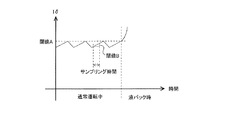
図3は本発明の実施の形態1に係るモータ制御装置200の負荷トルク検知手段26の閾値設定手法の一例を示す概念図である。図3の横軸には時間が規定されており、図3の縦軸にはトルク成分電流Iδが規定されている。
FIG. 3 is a conceptual diagram showing an example of a threshold setting method of the load torque detecting means 26 of the
空気調和機100が通常運転を行っている場合には、以下の2つの条件(4)及び条件(5)が同時に成立した場合、又はいずれか一方の条件を満足した場合に、圧縮機29の運転範囲外の負荷トルクが発生したものとして、電流補正手段27が動作する。
[数4]
現在Iδ検出値 > 閾値A ・・・(4)
[数5]
Iδ変化量 > 閾値B ・・・(5)When the
[Equation 4]
Current Iδ detection value> threshold value A (4)
[Equation 5]
Iδ change amount> threshold value B (5)
閾値Aは、圧縮機29の通常運転範囲におけるIδの最大値又は最大値を上回る値に設定される。閾値Bは、通常運転範囲内におけるモータ30のトルクリプルによって発生するトルク成分電流Iδの最大変化量又は最大変化量を上回る値に設定される。閾値A及び閾値Bの値は、例えば、事前に実機試験を行うことでそれぞれの値を測定して設定されている。トルク成分電流Iδの変化量の算出方法については、前述のとおりマイクロコンピュータ等によって検出する1サンプリング時間あたりの検出値の差分を用いる。モータ30の負荷トルクが増大すればトルク成分電流Iδも増加することが一般的に知られているため、閾値Bは、変化量が+側の値が設定されている。
The threshold A is set to a maximum value of Iδ in the normal operation range of the
次に電流補正手段27について説明する。電流補正手段27は、負荷トルク検知手段26が検知した負荷トルクが増加するほどモータ30に流れる電流を増加させるものである。電流補正手段27は、負荷トルク検知手段26によって検出した圧縮機29の通常運転範囲外の負荷トルク状態のときに、γ軸電流指令テーブル23による電流指令値からさらに電流指令値を増加させるように動作する。なお、電流指令値を増加させる手段としては、例えば、制御周期毎に予め定められた一定の電流指令値を加算することで行われる。モータ30の負荷トルクが増加しなくなり、Iδが、例えば、条件(4)及び条件(5)のうち少なくとも何れかを満足しなくなった場合には、電流補正手段27は、加算された電流指令値を減算し、元のγ軸電流指令テーブル23から得られるIγ電流指令値に戻す制御を行う。
Next, the current correction means 27 will be described. The current correction means 27 increases the current flowing through the
本実施の形態1に係るモータ制御装置200は、例えば低外気状態等において液冷媒が圧縮機29に吸入される液バック状態が発生し負荷トルクが急激に増加した状態であっても、γ軸電流指令値を増大させることによりモータ30に流れる電流が増加してモータ30が加熱され、圧縮機29内の液冷媒を気化させることができる。
The
なお、モータ30が何らかの異常により回転軸が固定されるようなロック故障が発生した場合には、モータ30に過大な電流が流れてモータ30の固定子巻線温度が発熱する場合がある。特に、圧縮機29の低回転数領域においてモータ30がロック故障すると、モータ30に印可されているインバータ出力電圧が小さいために、過電流保護手段15が動作しない電流範囲で運転が継続される可能性がある。その結果、長時間運転を継続することで、固定子巻線の温度が許容値以上になる場合がある。
When a lock failure occurs such that the rotating shaft is fixed due to some abnormality in the
しかしながら、本実施の形態1によれば、モータ30を制御するモータ制御装置200であって、モータ30の負荷トルクを検知する負荷トルク検知手段26と、負荷トルク検知手段26の検知情報に基づいてモータ30に流れる電流を制御する電流補正手段27と、を有し、電流補正手段27は、負荷トルク検知手段26が検知した負荷トルクが増加するほどモータ30に流れる電流を増加させる。このため、圧縮機29の低回転数領域でのモータロック故障状態であっても、負荷トルク検知手段26によってロック状態を早期に検知して電流補正手段27が動作してモータ30に流れる電流を増加させるため、γ軸電流が大きくなり過電流保護手段15を動作させることができ、固定子巻線の温度上昇が巻線許容温度を超える前に空気調和機100を安全に停止させることができる。したがって、モータ30の負荷トルクが増加した場合における脱調を回避して運転を継続させることができる。
However, according to the first embodiment, the
なお、本実施の形態1においては、永久磁石同期モータの位置センサレス制御方式として、磁束ベクトル制御を一例として説明したが、他の位置センサレス制御方式を採用し、負荷トルク検知手段26によって圧縮機29の通常運転範囲外の負荷トルクを検知した場合に各電流の指令値を補正するようにしてもよい。このようにしても、モータ30の脱調を回避して運転を継続させることができる。
In the first embodiment, the magnetic flux vector control has been described as an example of the position sensorless control method of the permanent magnet synchronous motor. However, another position sensorless control method is adopted, and the
また、低外気状態などにおいて液冷媒が圧縮機29に吸入される液バック状態が発生し負荷トルクが急激に増加した状態であっても、γ軸電流指令値を増大させることによりモータ30に過大な電流が流れてモータ30が加熱される。このため、冷媒の液バックを抑制することができ、モータ30のロック故障において空気調和機100を停止させることができる。
Further, even in a state where a liquid back state in which liquid refrigerant is sucked into the
実施の形態2.
本実施の形態2においては、実施の形態1とは異なり、負荷トルク検知手段26として、座標変換されたIδではなく、実効値算出手段26a、不平衡算出手段26b、力率算出手段26cを用いるようにしたものである。なお、本実施の形態2に係る空気調和機100は、実施の形態1とは異なる構成及び動作について説明し、実施の形態1の空気調和機100と同一の構成部材については同一の符号を用いるものとする。Embodiment 2. FIG.
In the second embodiment, unlike the first embodiment, the load torque detecting means 26 uses not the coordinate-converted Iδ but the effective value calculating means 26a, the unbalance calculating means 26b, and the power
図4は本発明の実施の形態2に係る空気調和機100及びモータ制御装置200の回路構成と制御ブロック図を示す概念図である。図5は本発明の実施の形態2に係るモータ制御装置200の磁束ベクトル制御を構成するベクトル図である。図4に示されるように、モータ制御装置200は、実効値算出手段26aと、不平衡算出手段26bと、力率算出手段26cと、を備える。
FIG. 4 is a conceptual diagram showing a circuit configuration and a control block diagram of the
実効値算出手段26aは、モータ30の各相電流の実効値(RMS)を算出するものである。なお、実効値の演算式は、周知のとおり交流電流1周期における2乗平均値に対して平方根を算出した結果から得られる。なお、交流電流1周期あたりの平均値を算出するとき、マイクロコンピュータの制御周期によるサンプリングから近似して算出してもよいし、交流電流が正弦波であれば、実効値は、瞬時値の最大値に対して√2で除することで算出できることが知られており、1周期あたりの瞬時値に対してピークホールド処理を施し、前述の式から電流実効値を求めてもよい。
The effective
不平衡算出手段26bは、実効値算出手段26aによって算出されるモータ30に流れる各相の電流実効値に対して、各相電流の実効値の差分を算出することで不平衡量を算出するものである。計算方法の一例を以下に示す。
ΔU−V = Iu(実効値)−Iv(実効値)
ΔV−W = Iv(実効値)−Iw(実効値)
ΔW−U = Iw(実効値)−Iu(実効値)
通常の圧縮機29の運転中であれば図6のように3相の電流実効値はバランスしているため、ΔU−V、ΔV−W、ΔW−Uはほぼ0Aとなる。モータ30がロックした状態等では、各相インダクタンスが不平衡になることでモータ30の三相交流電流が不平衡となる(図7)。また、モータ30とインバータ回路11とを接続する配線、又は固定子巻線等が断線した欠相運転状態においては、各相電流実効値の不平衡量より一層が大きくなる(図8)。The unbalance calculating means 26b calculates the unbalance amount by calculating the difference between the effective values of the respective phase currents with respect to the effective current values of the respective phases flowing through the
ΔU−V = Iu (effective value) −Iv (effective value)
ΔV−W = Iv (effective value) −Iw (effective value)
ΔW−U = Iw (effective value) −Iu (effective value)
If the
力率算出手段26cは、モータ30の力率を算出するものである。モータ30の電流瞬時値、各相の電流実効値の不平衡量、及び電圧位相と電流の位相差すなわちモータ30の力率に基づいて、モータ30の負荷トルク増加、モータ30のロック時の状態を検出する。
The power factor calculation means 26c calculates the power factor of the
電流補正手段27は、例えば、不平衡算出手段26bが算出された各相の電流実効値の差分ΔU−V、ΔV−W、ΔW−Uのうちのいずれか一つでも予め定めた第1基準値よりも大きい場合に、モータ30の負荷トルクが増加してモータ30が異常状態にあるものと判断して、γ軸電流指令値を加算させるようにモータ30を制御してモータ30の脱調を回避する。一般的にノイズや電流の歪み度合によって電流実効値が三相それぞれでバランスせず、モータ30が正常であるにもかかわらずΔU−V、ΔV−W、ΔW−Uが0にはならないことがあるため、第1基準値は、例えば、予め実機試験等により測定されたモータ30の通常運転範囲内での各相電流の実効値の差分よりも大きく設定する。さらに、同時に、実際にモータ30をロックさせた場合における電流実効値の不平衡量を測定することで、より確実に異常を検知できるように閾値を設定する。
The current correction means 27 is, for example, a first reference that is predetermined in any one of the differences ΔU−V, ΔV−W, and ΔW−U of the current effective values of the phases calculated by the unbalance calculation means 26b. If the value is larger than the value, it is determined that the load torque of the
電流補正手段27は、例えば、力率算出手段26cによって算出される力率が第2基準値以下である場合に、モータ30の負荷トルクが増加してモータ30が異常状態にあるものと判断して、γ軸電流指令値を加算させるようにモータ30を制御してモータ30の脱調を回避する。
For example, when the power factor calculated by the power
ここで、第2基準値は、例えば、予め実機試験等により測定されたモータ30の通常運転範囲内での力率値の最低値以下の値である。例えば、モータ30がロック故障した場合等に力率が悪化することが知られており、本実施の形態2のように構成することで、一層確実に圧縮機29の負荷トルクの急変又はモータ30の故障状態を検知することができる。
Here, the second reference value is, for example, a value equal to or less than the lowest value of the power factor value within the normal operation range of the
次に、本実施の形態2において、モータ制御装置200によって演算されるIγ、IδとVγ、Vδに基づいて力率を算出する方法について説明する。力率はモータ30に印可される電圧と電流との位相差によって求めることができる。
Next, a method of calculating the power factor based on Iγ, Iδ and Vγ, Vδ calculated by the
ここで、モータ30に印可される電圧は、VγとVδのベクトル和となることから、マイクロコンピュータ等によって電圧ベクトル和とγ―δ軸からの位相差θvを求めればよい。また本実施の形態2による磁束ベクトル制御では、γ軸とδ軸はそれぞれ直交していることから、VγとVδのベクトル和は三平方の定理を用いて求めることができ、電圧ベクトルの位相差について式(6)によって得ることができる(図5)。
[数6]
θv = Tan−1(Vδ/Vγ) ・・・(6)Here, since the voltage applied to the
[Equation 6]
θv = Tan −1 (Vδ / Vγ) (6)
また、モータ30に流れる電流は、IγとIδの電流ベクトル和より得ることができる。このため、上述した電圧ベクトルの位相差の説明と同様にして、電流ベクトルの位相差を式(7)によって得ることができる。
[数7]
θi = Tan−1(Iδ/Iγ) ・・・(7)Further, the current flowing through the
[Equation 7]
θi = Tan −1 (Iδ / Iγ) (7)
上記(6)式及び(7)式から得られたθvとθiの位相差をθv−iとすると、力率はCOS(θv−i)として求めることができる。 If the phase difference between θv and θi obtained from the above equations (6) and (7) is θv−i, the power factor can be obtained as COS (θv−i).
なお、圧縮機29の各相における電流実効値の不平衡を算出する不平衡算出手段26bと、モータ30の力率を算出する力率算出手段26cと、に基づいてモータ30に流れる電流を制御してもよい。具体的には例えば、電流補正手段27は、不平衡算出手段26bが算出された各相の電流実効値の不平衡量が予め定めた第1基準値よりも大きい場合、又は力率算出手段26cによって算出される力率が第2基準値以下である場合に、モータ30が異常状態にあるものと判断して、γ軸電流指令値を加算させるようにモータ30を制御してモータ30の脱調を回避してもよい。
The current flowing through the
なお、モータ制御装置200は、例えば、電流補正手段27の開始条件を満足しなくなった場合に、モータ30が正常に回転復帰したと判断する。モータ30が正常に回転復帰したことを一層確実に検知する場合には、例えば、モータ制御装置200は、実効値算出手段26aの算出値が所定値以下となった場合に、モータ30が正常に回転復帰したと判断する。そして、モータ30が正常に回転復帰すると、電流補正手段27は、加算したγ軸電流指令値を減算して通常の電流指令値に戻す。
Note that the
以上のように、本実施の形態2によれば、負荷トルク検知手段26は、モータ30の電流実効値を算出する実効値算出手段26aと、実効値算出手段26aによって算出される三相間の電流実効値の不平衡量を算出する不平衡算出手段26bと、をさらに備え、電流補正手段27は、不平衡算出手段26bによって算出される不平衡量が第1基準値よりも大きい場合に、負荷トルクが増加したものとしてモータ30に流れる電流を増加させる。このため、モータ30の負荷トルク急変時においてモータ30の脱調を回避し、またモータ30が何らかの故障状態であっても、γ軸電流を増大させることによって過電流保護手段15を早く動作させ、空気調和機100を安全に停止させることが可能となり、機器の信頼性を確保することができる。
As described above, according to the second embodiment, the load
また、本実施の形態2によれば、負荷トルク検知手段26は、モータ30の力率を算出する力率算出手段26cをさらに備え、電流補正手段27は、力率算出手段26cによって算出されるモータ30の力率が第2基準値以下である場合に、負荷トルクが増加したものとしてモータ30に流れる電流を増加させる。このため、モータ30の負荷トルク急変時においてモータ30の脱調を回避し、またモータ30が何らかの故障状態であっても、γ軸電流を増大させることによって過電流保護手段15を早く動作させ、空気調和機100を安全に停止させることが可能となり、機器の信頼性を確保することができる。
Further, according to the second embodiment, the load
また、本実施の形態2によれば、負荷トルク検知手段26は、モータ30の電流実効値を算出する実効値算出手段26aと、実効値算出手段26aによって算出される三相間の電流実効値の不平衡量を算出する不平衡算出手段26bと、モータ30の力率を算出する力率算出手段26cと、をさらに備え、電流補正手段27は、不平衡算出手段26bによって算出される不平衡量が第1基準値よりも大きい場合又は力率算出手段26cによって算出されるモータ30の力率が第2基準値以下である場合に、負荷トルクが増加したものとしてモータ30に流れる電流を増加させる。このため、モータ30の負荷トルク急変時においてモータ30の脱調を回避し、またモータ30が何らかの故障状態であっても、γ軸電流を増大させることによって過電流保護手段15を早く動作させ、空気調和機を安全に停止させることが可能となり、機器の信頼性を確保することができる。
Further, according to the second embodiment, the load torque detection means 26 is an effective value calculation means 26a for calculating the effective current value of the
10 平滑コンデンサ、11 インバータ回路、12 スイッチング素子、13 電流検出手段、14 ゲート駆動回路、15 過電流保護手段、20 座標変換手段、21 回転数指令生成手段、22 積分手段、23 γ軸電流テーブル、24 周波数補償手段、25 電圧指令演算手段、26 負荷トルク検知手段、26a 実効値算出手段、26b 不平衡算出手段、26c 力率算出手段、27 電流補正手段、28 逆座標変換手段、29 圧縮機、30 モータ、31 凝縮器、32 減圧装置、33 蒸発器、100 空気調和機、200 モータ制御装置。
DESCRIPTION OF
Claims (9)
前記モータの負荷トルクを検知する負荷トルク検知手段と、
前記負荷トルク検知手段が検知した前記負荷トルクが増加するほど前記モータに流れる電流を増加させる電流補正手段と、を有し、
前記負荷トルク検知手段は、
前記モータの力率を算出する力率算出手段を備え、
前記電流補正手段は、
前記力率算出手段によって算出される前記モータの力率が第2基準値以下である場合に、前記負荷トルクが増加したものとして前記モータに流れる電流を増加させる
モータ制御装置。 A motor control device for controlling a motor,
Load torque detecting means for detecting the load torque of the motor;
Current correction means for increasing the current flowing through the motor as the load torque detected by the load torque detection means increases ;
The load torque detecting means is
Power factor calculating means for calculating the power factor of the motor;
The current correction means includes
A motor control device that, when the power factor of the motor calculated by the power factor calculation means is equal to or less than a second reference value , increases the current flowing through the motor as an increase in the load torque .
前記モータの負荷トルクを検知する負荷トルク検知手段と、
前記負荷トルク検知手段が検知した前記負荷トルクが増加するほど前記モータに流れる電流を増加させる電流補正手段と、を有し、
前記負荷トルク検知手段は、
前記モータの電流実効値を算出する実効値算出手段と、
前記実効値算出手段によって算出される三相間の電流実効値の不平衡量を算出する不平衡算出手段と、を備え、
前記電流補正手段は、
前記不平衡算出手段によって算出される前記不平衡量が第1基準値よりも大きい場合に、前記負荷トルクが増加したものとして前記モータに流れる電流を増加させる
モータ制御装置。 A motor control device for controlling a motor,
Load torque detecting means for detecting the load torque of the motor;
Current correction means for increasing the current flowing through the motor as the load torque detected by the load torque detection means increases ;
The load torque detecting means is
An effective value calculating means for calculating an effective current value of the motor;
An unbalance calculation means for calculating an unbalance amount of the current effective value between the three phases calculated by the effective value calculation means,
The current correction means includes
A motor control device that increases the current flowing through the motor as an increase in the load torque when the unbalance amount calculated by the unbalance calculation means is greater than a first reference value .
前記モータの負荷トルクを検知する負荷トルク検知手段と、
前記負荷トルク検知手段が検知した前記負荷トルクが増加するほど前記モータに流れる電流を増加させる電流補正手段と、を有し、
前記負荷トルク検知手段は、
前記モータの電流実効値を算出する実効値算出手段と、
前記実効値算出手段によって算出される三相間の電流実効値の不平衡量を算出する不平衡算出手段と、
前記モータの力率を算出する力率算出手段と、を備え、
前記電流補正手段は、
前記不平衡算出手段によって算出される前記不平衡量が第1基準値よりも大きい場合又は前記力率算出手段によって算出される前記モータの力率が第2基準値以下である場合に、前記負荷トルクが増加したものとして前記モータに流れる電流を増加させる
モータ制御装置。 A motor control device for controlling a motor,
Load torque detecting means for detecting the load torque of the motor;
Current correction means for increasing the current flowing through the motor as the load torque detected by the load torque detection means increases ;
The load torque detecting means is
An effective value calculating means for calculating an effective current value of the motor;
An unbalance calculation means for calculating an unbalance amount of a current effective value between three phases calculated by the effective value calculation means;
Power factor calculating means for calculating the power factor of the motor,
The current correction means includes
The load torque when the unbalance amount calculated by the unbalance calculation means is larger than a first reference value or when the power factor of the motor calculated by the power factor calculation means is less than or equal to a second reference value. There motor controller to increase the current flowing through the motor as increased.
請求項1〜請求項3の何れか一項に記載のモータ制御装置。 The motor control device according to any one of claims 1 to 3, further comprising position sensorless control means for performing control so as to maintain a total magnetic flux of the motor at a reference value.
圧縮機。 The compressor provided with the said motor controlled by the motor control apparatus as described in any one of Claims 1-4 .
前記モータの電流を検出する電流検出手段と、
前記電流検出手段によって検出される電流値が電流基準値以上である場合に前記モータ制御装置を停止させる過電流保護手段と、を備えた
空気調和機。 A compressor according to claim 5 ;
Current detecting means for detecting the current of the motor;
And an overcurrent protection unit that stops the motor control device when a current value detected by the current detection unit is equal to or greater than a current reference value.
三相交流電源の整流された直流電圧を平滑する平滑コンデンサと、
前記平滑コンデンサにより平滑された直流電圧を交流電圧に変換するインバータ回路と、を備えた
空気調和機。 A compressor according to claim 5 ;
A smoothing capacitor that smoothes the rectified DC voltage of the three-phase AC power supply;
An air conditioner comprising: an inverter circuit that converts a DC voltage smoothed by the smoothing capacitor into an AC voltage.
炭化珪素素子、窒化ガリウム系の素子、又はダイヤモンド素子によって構成される
請求項7に記載の空気調和機。 The switching element of the inverter circuit is
The air conditioner according to claim 7 , wherein the air conditioner is configured by a silicon carbide element, a gallium nitride-based element, or a diamond element.
空気調和機。 An air conditioner having a refrigeration cycle circuit configured by connecting the compressor according to claim 5 , a condenser, a decompression device, and an evaporator through a refrigerant pipe.
Applications Claiming Priority (1)
| Application Number | Priority Date | Filing Date | Title |
|---|---|---|---|
| PCT/JP2015/069948 WO2017009907A1 (en) | 2015-07-10 | 2015-07-10 | Motor control device, compressor, and air conditioner |
Publications (2)
| Publication Number | Publication Date |
|---|---|
| JPWO2017009907A1 JPWO2017009907A1 (en) | 2018-02-22 |
| JP6410939B2 true JP6410939B2 (en) | 2018-10-24 |
Family
ID=57757849
Family Applications (1)
| Application Number | Title | Priority Date | Filing Date |
|---|---|---|---|
| JP2017528018A Active JP6410939B2 (en) | 2015-07-10 | 2015-07-10 | Motor control device, compressor, and air conditioner |
Country Status (3)
| Country | Link |
|---|---|
| EP (1) | EP3322087A4 (en) |
| JP (1) | JP6410939B2 (en) |
| WO (1) | WO2017009907A1 (en) |
Families Citing this family (2)
| Publication number | Priority date | Publication date | Assignee | Title |
|---|---|---|---|---|
| WO2020031526A1 (en) * | 2018-08-07 | 2020-02-13 | 日本電産株式会社 | Drive control device, drive device, and power steering device |
| CN115095968A (en) * | 2022-07-08 | 2022-09-23 | 北京小米移动软件有限公司 | Torque compensation control method, device and storage medium |
Family Cites Families (11)
| Publication number | Priority date | Publication date | Assignee | Title |
|---|---|---|---|---|
| JP2001169597A (en) * | 1999-12-03 | 2001-06-22 | Yaskawa Electric Corp | Method and device for correcting dc component in drive current of synchronous motor |
| JP2005059786A (en) * | 2003-08-18 | 2005-03-10 | Koyo Seiko Co Ltd | Electrically powered steering device |
| JP4578142B2 (en) * | 2004-04-22 | 2010-11-10 | 日本電産シバウラ株式会社 | Brushless DC motor drive device |
| JP4641179B2 (en) * | 2004-11-25 | 2011-03-02 | 川崎重工業株式会社 | Synchronous motor control method and control apparatus |
| CN101449456B (en) * | 2006-08-31 | 2012-11-28 | 三菱电机株式会社 | Electromotor driving device and compressor driving device |
| JP4930085B2 (en) * | 2007-02-08 | 2012-05-09 | 株式会社富士通ゼネラル | Phase detection method, phase detection device, synchronous motor control method, and synchronous motor control device |
| JP5175887B2 (en) * | 2010-03-23 | 2013-04-03 | 株式会社東芝 | Motor control device and electrical equipment |
| US8487557B2 (en) * | 2011-02-15 | 2013-07-16 | General Electric Company | Use of motor protection system to protect process operation |
| JP5253593B2 (en) * | 2012-02-14 | 2013-07-31 | 三菱電機株式会社 | Air conditioner |
| JP5851303B2 (en) * | 2012-03-28 | 2016-02-03 | 三菱電機株式会社 | Refrigeration cycle apparatus and outdoor heat source unit |
| CN103701372B (en) * | 2012-09-27 | 2017-07-04 | 比亚迪股份有限公司 | A kind of step failing out detecting method of synchronous motor |
-
2015
- 2015-07-10 WO PCT/JP2015/069948 patent/WO2017009907A1/en active Application Filing
- 2015-07-10 JP JP2017528018A patent/JP6410939B2/en active Active
- 2015-07-10 EP EP15898223.1A patent/EP3322087A4/en active Pending
Also Published As
| Publication number | Publication date |
|---|---|
| JPWO2017009907A1 (en) | 2018-02-22 |
| EP3322087A1 (en) | 2018-05-16 |
| EP3322087A4 (en) | 2018-07-11 |
| WO2017009907A1 (en) | 2017-01-19 |
Similar Documents
| Publication | Publication Date | Title |
|---|---|---|
| JP6333563B2 (en) | Inverter control apparatus and refrigeration apparatus using the same | |
| JP3684203B2 (en) | Motor control device | |
| WO2016002074A1 (en) | Power converter, dehumidifier, air conditioner, and refrigeration equipment | |
| JP7004869B2 (en) | Drive and air conditioner | |
| JP7105961B2 (en) | Motor drive device and refrigeration cycle application equipment | |
| JP2002247876A (en) | Inverter device, compressor controlling device, freezer and air conditioner controlling device, motor controlling method, compressor, freezer and air conditioner | |
| JP4804100B2 (en) | Motor drive device, control method therefor, and air conditioner | |
| JP6410939B2 (en) | Motor control device, compressor, and air conditioner | |
| JP2009153247A (en) | Motor drive controller, motor drive control method and coordinate conversion method, and ventilation fan, liquid pump, blower, refrigerant compressor, air conditioner and refrigerator | |
| JP2010226842A (en) | Control method and control apparatus for brushless dc motor | |
| JP6929434B2 (en) | Motor drive device and refrigeration cycle applicable equipment | |
| JP2004040861A (en) | Driving-gear of motor | |
| WO2014155622A1 (en) | Heat pump device, air conditioner, and freezer | |
| JP6309173B2 (en) | Motor drive device, heat pump device using the motor drive device, refrigeration air conditioner, and blower | |
| JP2014187802A (en) | Motor drive device | |
| JPWO2014049867A1 (en) | Heat pump device, air conditioner and refrigerator | |
| CN112219350B (en) | Motor drive device, control device for motor drive device, control method for motor drive device, and air conditioner | |
| JP2012165582A (en) | Motor controller | |
| JP2009189106A (en) | Apparatus and method for motor control | |
| JP2006136167A (en) | Power converter, control method of power converter, and air conditioner | |
| WO2023095311A1 (en) | Power conversion device, electric motor drive device, and refrigeration-cycle-applicable apparatus | |
| WO2023162106A1 (en) | Motor drive device and refrigeration cycle device | |
| JP2010288348A (en) | Controller for synchronous motor, and freezer and air conditioner using the same | |
| JP7217833B1 (en) | Motor drive device, electrical constant measurement method and refrigeration equipment | |
| CN112272917B (en) | Motor driving device and refrigeration cycle application equipment |
Legal Events
| Date | Code | Title | Description |
|---|---|---|---|
| A521 | Request for written amendment filed |
Free format text: JAPANESE INTERMEDIATE CODE: A523 Effective date: 20171020 |
|
| A621 | Written request for application examination |
Free format text: JAPANESE INTERMEDIATE CODE: A621 Effective date: 20171020 |
|
| TRDD | Decision of grant or rejection written | ||
| A01 | Written decision to grant a patent or to grant a registration (utility model) |
Free format text: JAPANESE INTERMEDIATE CODE: A01 Effective date: 20180828 |
|
| A61 | First payment of annual fees (during grant procedure) |
Free format text: JAPANESE INTERMEDIATE CODE: A61 Effective date: 20180925 |
|
| R150 | Certificate of patent or registration of utility model |
Ref document number: 6410939 Country of ref document: JP Free format text: JAPANESE INTERMEDIATE CODE: R150 |
|
| R250 | Receipt of annual fees |
Free format text: JAPANESE INTERMEDIATE CODE: R250 |
|
| R250 | Receipt of annual fees |
Free format text: JAPANESE INTERMEDIATE CODE: R250 |
|
| R250 | Receipt of annual fees |
Free format text: JAPANESE INTERMEDIATE CODE: R250 |