JP5339552B2 - Body fluid component analyzer - Google Patents
Body fluid component analyzer Download PDFInfo
- Publication number
- JP5339552B2 JP5339552B2 JP2011509102A JP2011509102A JP5339552B2 JP 5339552 B2 JP5339552 B2 JP 5339552B2 JP 2011509102 A JP2011509102 A JP 2011509102A JP 2011509102 A JP2011509102 A JP 2011509102A JP 5339552 B2 JP5339552 B2 JP 5339552B2
- Authority
- JP
- Japan
- Prior art keywords
- sample
- plate
- flow path
- reaction chamber
- hole
- Prior art date
- Legal status (The legal status is an assumption and is not a legal conclusion. Google has not performed a legal analysis and makes no representation as to the accuracy of the status listed.)
- Expired - Fee Related
Links
- 210000001124 body fluid Anatomy 0.000 title claims description 38
- 239000010839 body fluid Substances 0.000 title claims description 32
- 239000007788 liquid Substances 0.000 claims description 32
- 239000002699 waste material Substances 0.000 claims description 32
- 238000004458 analytical method Methods 0.000 claims description 30
- XLYOFNOQVPJJNP-UHFFFAOYSA-N water Substances O XLYOFNOQVPJJNP-UHFFFAOYSA-N 0.000 claims description 19
- 239000011148 porous material Substances 0.000 claims description 18
- 239000012491 analyte Substances 0.000 claims description 12
- 238000011144 upstream manufacturing Methods 0.000 claims description 9
- 230000008859 change Effects 0.000 claims description 7
- 230000003287 optical effect Effects 0.000 claims description 7
- 230000002940 repellent Effects 0.000 claims description 7
- 239000005871 repellent Substances 0.000 claims description 7
- 230000035699 permeability Effects 0.000 claims description 5
- 238000012546 transfer Methods 0.000 claims description 5
- 238000010030 laminating Methods 0.000 claims description 2
- 238000007789 sealing Methods 0.000 claims description 2
- 238000009423 ventilation Methods 0.000 claims description 2
- 102000017011 Glycated Hemoglobin A Human genes 0.000 description 17
- 108091005995 glycated hemoglobin Proteins 0.000 description 17
- 239000000126 substance Substances 0.000 description 13
- 102000001554 Hemoglobins Human genes 0.000 description 11
- 108010054147 Hemoglobins Proteins 0.000 description 11
- 239000000463 material Substances 0.000 description 8
- 230000000903 blocking effect Effects 0.000 description 7
- 238000005259 measurement Methods 0.000 description 7
- 238000000034 method Methods 0.000 description 6
- 239000013076 target substance Substances 0.000 description 6
- 239000002245 particle Substances 0.000 description 5
- 238000010586 diagram Methods 0.000 description 4
- 230000000694 effects Effects 0.000 description 4
- 238000001914 filtration Methods 0.000 description 4
- 239000007850 fluorescent dye Substances 0.000 description 4
- 238000002372 labelling Methods 0.000 description 4
- 239000000243 solution Substances 0.000 description 4
- 238000003860 storage Methods 0.000 description 4
- 210000004369 blood Anatomy 0.000 description 3
- 239000008280 blood Substances 0.000 description 3
- 210000003743 erythrocyte Anatomy 0.000 description 3
- 239000000439 tumor marker Substances 0.000 description 3
- XPDXVDYUQZHFPV-UHFFFAOYSA-N Dansyl Chloride Chemical compound C1=CC=C2C(N(C)C)=CC=CC2=C1S(Cl)(=O)=O XPDXVDYUQZHFPV-UHFFFAOYSA-N 0.000 description 2
- 206010018910 Haemolysis Diseases 0.000 description 2
- 230000009471 action Effects 0.000 description 2
- 229920002678 cellulose Polymers 0.000 description 2
- 239000001913 cellulose Substances 0.000 description 2
- 229920002301 cellulose acetate Polymers 0.000 description 2
- 238000011161 development Methods 0.000 description 2
- 238000010790 dilution Methods 0.000 description 2
- 239000012895 dilution Substances 0.000 description 2
- 150000002148 esters Chemical class 0.000 description 2
- 239000012530 fluid Substances 0.000 description 2
- MHMNJMPURVTYEJ-UHFFFAOYSA-N fluorescein-5-isothiocyanate Chemical compound O1C(=O)C2=CC(N=C=S)=CC=C2C21C1=CC=C(O)C=C1OC1=CC(O)=CC=C21 MHMNJMPURVTYEJ-UHFFFAOYSA-N 0.000 description 2
- PCHJSUWPFVWCPO-UHFFFAOYSA-N gold Chemical compound [Au] PCHJSUWPFVWCPO-UHFFFAOYSA-N 0.000 description 2
- 230000008588 hemolysis Effects 0.000 description 2
- 230000002949 hemolytic effect Effects 0.000 description 2
- 230000008105 immune reaction Effects 0.000 description 2
- 239000004816 latex Substances 0.000 description 2
- 229920000126 latex Polymers 0.000 description 2
- 230000000149 penetrating effect Effects 0.000 description 2
- -1 polyethylene terephthalate Polymers 0.000 description 2
- 229920000139 polyethylene terephthalate Polymers 0.000 description 2
- 239000005020 polyethylene terephthalate Substances 0.000 description 2
- 239000004810 polytetrafluoroethylene Substances 0.000 description 2
- 229920001343 polytetrafluoroethylene Polymers 0.000 description 2
- 238000012545 processing Methods 0.000 description 2
- 230000000717 retained effect Effects 0.000 description 2
- 238000002834 transmittance Methods 0.000 description 2
- HDTRYLNUVZCQOY-UHFFFAOYSA-N α-D-glucopyranosyl-α-D-glucopyranoside Natural products OC1C(O)C(O)C(CO)OC1OC1C(O)C(O)C(O)C(CO)O1 HDTRYLNUVZCQOY-UHFFFAOYSA-N 0.000 description 1
- FBPFZTCFMRRESA-FSIIMWSLSA-N D-Glucitol Natural products OC[C@H](O)[C@H](O)[C@@H](O)[C@H](O)CO FBPFZTCFMRRESA-FSIIMWSLSA-N 0.000 description 1
- FBPFZTCFMRRESA-JGWLITMVSA-N D-glucitol Chemical compound OC[C@H](O)[C@@H](O)[C@H](O)[C@H](O)CO FBPFZTCFMRRESA-JGWLITMVSA-N 0.000 description 1
- CZMRCDWAGMRECN-UGDNZRGBSA-N Sucrose Chemical compound O[C@H]1[C@H](O)[C@@H](CO)O[C@@]1(CO)O[C@@H]1[C@H](O)[C@@H](O)[C@H](O)[C@@H](CO)O1 CZMRCDWAGMRECN-UGDNZRGBSA-N 0.000 description 1
- 229930006000 Sucrose Natural products 0.000 description 1
- AUYYCJSJGJYCDS-LBPRGKRZSA-N Thyrolar Chemical class IC1=CC(C[C@H](N)C(O)=O)=CC(I)=C1OC1=CC=C(O)C(I)=C1 AUYYCJSJGJYCDS-LBPRGKRZSA-N 0.000 description 1
- HDTRYLNUVZCQOY-WSWWMNSNSA-N Trehalose Natural products O[C@@H]1[C@@H](O)[C@@H](O)[C@@H](CO)O[C@@H]1O[C@@H]1[C@H](O)[C@@H](O)[C@@H](O)[C@@H](CO)O1 HDTRYLNUVZCQOY-WSWWMNSNSA-N 0.000 description 1
- 238000002835 absorbance Methods 0.000 description 1
- 239000012790 adhesive layer Substances 0.000 description 1
- HDTRYLNUVZCQOY-LIZSDCNHSA-N alpha,alpha-trehalose Chemical compound O[C@@H]1[C@@H](O)[C@H](O)[C@@H](CO)O[C@@H]1O[C@@H]1[C@H](O)[C@@H](O)[C@H](O)[C@@H](CO)O1 HDTRYLNUVZCQOY-LIZSDCNHSA-N 0.000 description 1
- 238000009739 binding Methods 0.000 description 1
- 230000005540 biological transmission Effects 0.000 description 1
- 210000000601 blood cell Anatomy 0.000 description 1
- 238000004587 chromatography analysis Methods 0.000 description 1
- 238000004140 cleaning Methods 0.000 description 1
- 239000011248 coating agent Substances 0.000 description 1
- 238000000576 coating method Methods 0.000 description 1
- 230000009918 complex formation Effects 0.000 description 1
- 230000008602 contraction Effects 0.000 description 1
- 238000001514 detection method Methods 0.000 description 1
- 238000001035 drying Methods 0.000 description 1
- 230000004907 flux Effects 0.000 description 1
- 238000007429 general method Methods 0.000 description 1
- 150000004676 glycans Chemical class 0.000 description 1
- 230000002209 hydrophobic effect Effects 0.000 description 1
- 230000036039 immunity Effects 0.000 description 1
- 238000003317 immunochromatography Methods 0.000 description 1
- 238000012423 maintenance Methods 0.000 description 1
- 238000004519 manufacturing process Methods 0.000 description 1
- 239000012466 permeate Substances 0.000 description 1
- 238000005375 photometry Methods 0.000 description 1
- 239000004033 plastic Substances 0.000 description 1
- 229920003023 plastic Polymers 0.000 description 1
- 229920001282 polysaccharide Polymers 0.000 description 1
- 239000005017 polysaccharide Substances 0.000 description 1
- 230000008569 process Effects 0.000 description 1
- 239000001397 quillaja saponaria molina bark Substances 0.000 description 1
- 239000011347 resin Substances 0.000 description 1
- 229920005989 resin Polymers 0.000 description 1
- PYWVYCXTNDRMGF-UHFFFAOYSA-N rhodamine B Chemical compound [Cl-].C=12C=CC(=[N+](CC)CC)C=C2OC2=CC(N(CC)CC)=CC=C2C=1C1=CC=CC=C1C(O)=O PYWVYCXTNDRMGF-UHFFFAOYSA-N 0.000 description 1
- 229930182490 saponin Natural products 0.000 description 1
- 150000007949 saponins Chemical class 0.000 description 1
- 238000000926 separation method Methods 0.000 description 1
- 239000000600 sorbitol Substances 0.000 description 1
- 238000001179 sorption measurement Methods 0.000 description 1
- 239000005720 sucrose Substances 0.000 description 1
- 239000004094 surface-active agent Substances 0.000 description 1
- 239000005495 thyroid hormone Substances 0.000 description 1
- 229940036555 thyroid hormone Drugs 0.000 description 1
Images


Classifications
-
- G—PHYSICS
- G01—MEASURING; TESTING
- G01N—INVESTIGATING OR ANALYSING MATERIALS BY DETERMINING THEIR CHEMICAL OR PHYSICAL PROPERTIES
- G01N33/00—Investigating or analysing materials by specific methods not covered by groups G01N1/00 - G01N31/00
- G01N33/48—Biological material, e.g. blood, urine; Haemocytometers
- G01N33/50—Chemical analysis of biological material, e.g. blood, urine; Testing involving biospecific ligand binding methods; Immunological testing
- G01N33/53—Immunoassay; Biospecific binding assay; Materials therefor
- G01N33/543—Immunoassay; Biospecific binding assay; Materials therefor with an insoluble carrier for immobilising immunochemicals
- G01N33/54366—Apparatus specially adapted for solid-phase testing
- G01N33/54386—Analytical elements
- G01N33/54387—Immunochromatographic test strips
- G01N33/54388—Immunochromatographic test strips based on lateral flow
- G01N33/54389—Immunochromatographic test strips based on lateral flow with bidirectional or multidirectional lateral flow, e.g. wherein the sample flows from a single, common sample application point into multiple strips, lanes or zones
Landscapes
- Health & Medical Sciences (AREA)
- Immunology (AREA)
- Life Sciences & Earth Sciences (AREA)
- Engineering & Computer Science (AREA)
- Molecular Biology (AREA)
- Biomedical Technology (AREA)
- Chemical & Material Sciences (AREA)
- Hematology (AREA)
- Urology & Nephrology (AREA)
- Biotechnology (AREA)
- Microbiology (AREA)
- Cell Biology (AREA)
- Food Science & Technology (AREA)
- Medicinal Chemistry (AREA)
- Physics & Mathematics (AREA)
- Analytical Chemistry (AREA)
- Biochemistry (AREA)
- General Health & Medical Sciences (AREA)
- General Physics & Mathematics (AREA)
- Pathology (AREA)
- Automatic Analysis And Handling Materials Therefor (AREA)
Description
本発明は生体の体液中の特定成分、特に糖化ヘモグロビン、腫瘍マーカー、甲状腺ホルモンなどの免疫反応を利用して検出する成分を、簡易に測定する分析器具に関する。 The present invention relates to an analytical instrument for easily measuring a specific component in a body fluid of a living body, in particular, a component detected using an immune reaction such as glycated hemoglobin, a tumor marker, and a thyroid hormone.
従来免疫反応を利用した簡易的な器具として、イムノクロマトを利用した器具が知られている(特許文献1参照)。典型例としては、液体が毛管現象で移動することができる多孔質材からなるストリップの一部に、分析対象物質に特異的に結合する抗体が固定化されており(固定化抗体)、その上流に金コロイドなどの着色粒子で標識された、分析対象物質に特異的に結合する抗体(標識抗体)が、ストリップ上に固定されていない状態で配置されている器具が挙げられる。これに標識抗体の上流から試料を滴下すると、試料はストリップ中の毛管を伝わって浸透し標識抗体を溶解し、さらに、標識抗体とともにストリップの抗体を固定化した部位を通過してストリップの下流に移動するが、試料中に分析対象物質が存在する場合には、溶解した標識抗体と反応し、ついでストリップに固定化された抗体に「分析対象物質−標識抗体」複合体として捕獲される。未反応の標識抗体は下流に移動してしまうため、分析対象物質が存在する場合にだけストリップの抗体を固定化した部分に金コロイドによる着色が観察される。この器具は簡易に測定が可能ではあるが、試料の展開速度が多孔質材からなるストリップのクロマト作用に依存しているため、展開速度で規定される抗原−抗体反応の時間を一定に制御することができないという問題があった。 Conventionally, an instrument using immunochromatography is known as a simple instrument using an immune reaction (see Patent Document 1). As a typical example, an antibody that specifically binds to a substance to be analyzed is immobilized on a part of a strip made of a porous material in which a liquid can move by capillary action (immobilized antibody), and upstream thereof. An instrument in which an antibody that specifically binds to a substance to be analyzed (labeled antibody) labeled with colored particles such as colloidal gold is arranged on the strip in an unfixed state. When the sample is dropped from the upstream of the labeled antibody, the sample penetrates through the capillary in the strip and dissolves the labeled antibody, and further passes through the site where the antibody of the strip is immobilized together with the labeled antibody to the downstream of the strip. If the analyte is present in the sample, it reacts with the dissolved labeled antibody, and is then captured by the antibody immobilized on the strip as an “analyte-labeled antibody” complex. Since the unreacted labeled antibody moves downstream, coloration by colloidal gold is observed only in the portion where the antibody is immobilized on the strip only when the analyte is present. Although this instrument can measure easily, the development speed of the sample depends on the chromatographic action of the strip made of a porous material, so the time of the antigen-antibody reaction defined by the development speed is controlled to be constant. There was a problem that I could not.
一方、試料をクロマト移動させることに代え、ポンプによる吸引によって流路を通じて試料を移送させる器具が知られている(特許文献2参照)。この器具は、順に、試料供給口、標識抗体が備えられた試料処理室、固定化抗体が備えられた測定室、廃液室およびポンプ接続口が、流路により連通している。試料を試料供給口に滴下した後、ポンプによる吸引によってまず試料処理室に移送し、標識抗体を遊離させるとともに試料に含まれる分析対象物質と抗原抗体反応を生じさせる。そこで所定の時間停止した後、再び吸引して測定室に移送し、分析対象物質と標識抗体との結合物を抗原抗体反応により固定化抗体に結合させ、そこで所定の時間停止した後、吸引して廃液室に移送する。そして測定室について測光することによって試料に含まれる分析対象物質の定量測定を実施することができる。この器具は、ポンプにより試料を能動的に移送させる構成となっているため、移送速度を制御することが可能となる。しかし、特に微小な領域で微量な試料の移送をする場合、吸引動作の微細な制御が不可欠となり、ポンプの微小な作動誤差や微小領域に存在する空気の膨張収縮などの影響により、測定結果が大きな影響を受けるという問題があった。 On the other hand, instead of moving the sample by chromatography, an instrument is known that transfers the sample through a flow path by suction with a pump (see Patent Document 2). In this instrument, a sample supply port, a sample processing chamber equipped with a labeled antibody, a measurement chamber equipped with an immobilized antibody, a waste fluid chamber, and a pump connection port are communicated with each other through a flow path. After the sample is dropped into the sample supply port, it is first transferred to the sample processing chamber by suction with a pump to release the labeled antibody and cause an antigen-antibody reaction with the analyte to be contained in the sample. Therefore, after stopping for a predetermined time, the liquid is aspirated again and transferred to the measurement chamber, and the combined substance of the analyte and the labeled antibody is bound to the immobilized antibody by the antigen-antibody reaction. To the waste liquid chamber. Then, by performing photometry on the measurement chamber, quantitative measurement of the analysis target substance contained in the sample can be performed. Since this instrument is configured to actively transfer a sample by a pump, the transfer speed can be controlled. However, especially when transferring a small amount of sample in a small area, fine control of the suction operation is indispensable, and the measurement results may be affected by the effects of minute operation errors of the pump and the expansion and contraction of air existing in the small area. There was a problem of being greatly affected.
そこで、簡易な操作で分析を実施することができ、精度が高い分析結果を迅速に得ることができ、さらには分析に要するコストが低廉であるような、体液の特定成分を分析するための分析器具が求められていた。 Therefore, it is possible to perform analysis with simple operations, to obtain high-precision analysis results quickly, and to analyze specific components of body fluids that require low cost for analysis. An instrument was sought.
ところで、本願発明者らの検討によれば、体液成分の分析器具の試料供給口に可撓性を有するカップ型の容器の開口を当接し、ストローク量を制御して容器の底部を圧縮すると、容器内の圧力は制御の直接の対象であるストローク量とほぼ線形の関係を有し、かつ圧力の再現性も高いということが明らかになった。すなわち、ストロークを制御することによって、試料を器具内で移動させるために付与すべき圧力を、高い再現性のもとで制御することが可能であることが明らかとなった。 By the way, according to the study by the inventors of the present application, when the opening of the cup-shaped container having flexibility is brought into contact with the sample supply port of the body fluid component analysis instrument and the bottom of the container is compressed by controlling the stroke amount, It has been clarified that the pressure in the container has a substantially linear relationship with the stroke amount that is directly controlled, and the pressure reproducibility is high. That is, it became clear that the pressure to be applied to move the sample in the instrument can be controlled with high reproducibility by controlling the stroke.
そこで、本発明が解決しようとする課題は、本願発明者らの知見により明らかとなった上述の圧力の高い再現性を利用することによって、分析器具の製造公差や微小な作動誤差などに左右されることなく、精度が高い分析結果を迅速に得ることができ、さらには分析に要するコストが低廉であるような、体液の特定成分を分析するための分析器具を提供することである。 Therefore, the problem to be solved by the present invention depends on the manufacturing tolerance of the analytical instrument, minute operation error, etc. by utilizing the high reproducibility of the pressure described above, which has been clarified by the inventors' knowledge. It is an object of the present invention to provide an analytical instrument for analyzing a specific component of a body fluid so that an analysis result with high accuracy can be quickly obtained and the cost required for the analysis is low.
本発明は、前記課題を解決するためになされたもので、請求項1に記載の発明は、試料が内部に供給される試料供給口と、前記試料供給口から延出する第1の流路と、前記第1の流路に連通する反応室と、前記反応室から延出する第2の流路と、前記第2の流路に連通する廃液室と、前記第2の流路を閉塞するよう設けられた閉塞部材とを備え、前記閉塞部材は、通気性を有するとともに、所定の圧力より低い圧では通水せず、前記所定の圧力以上の圧力で通水し、前記反応室を取り囲み対面する2つの壁面が光透過性を有し、前記2つの壁面のいずれか一方に前記試料に含まれる分析対象物質と特異的に結合する抗体が固定化されており、さらに前記反応室に前記分析対象物質と特異的に結合する標識された抗体が遊離可能に保持されており、前記廃液室を取り囲む壁面の少なくとも一部が通気性を有することを特徴とする体液成分の分析器具である。
The present invention has been made to solve the above problems, and the invention according to
請求項1に記載の発明によれば、分析対象物質を含む試料を試料供給口に滴下し試料供給口を所定の圧力より低い圧力で加圧すると、試料は第1の流路を通り反応室に移送されるとともに、そこで滞留して抗原抗体反応が起こり、標識された抗体と結合した分析対象物質がさらに固定化された抗体と結合することによって反応室内に捕捉され、その後試料供給口を所定の圧力以上で加圧すると、滞留していた試料が閉塞部材を通過するため、未反応の標識された抗体を試料とともに廃液室に移送することが可能な、体液成分の分析器具を提供することができる。当該分析器具を用いれば、微細な吸引動作の制御を必要とすることなく、試料に含まれる分析対象物質を反応室に捕捉することができ、反応室の光学的変化量を計測することにより分析対象物質を定量的に測定することができる。 According to the first aspect of the present invention, when a sample containing the substance to be analyzed is dropped on the sample supply port and the sample supply port is pressurized at a pressure lower than a predetermined pressure, the sample passes through the first channel and is in the reaction chamber. The substance to be analyzed stays there and undergoes an antigen-antibody reaction. The analyte to be bound to the labeled antibody is further bound to the immobilized antibody to be captured in the reaction chamber. To provide a body fluid component analysis instrument capable of transferring unreacted labeled antibody to a waste fluid chamber together with a sample because a retained sample passes through a blocking member when pressurized at a pressure higher than Can do. By using the analytical instrument, it is possible to capture the analyte in the sample in the reaction chamber without the need for fine suction control, and to analyze by measuring the optical change in the reaction chamber The target substance can be measured quantitatively.
請求項2に記載の発明は、前記閉塞部材が撥水処理された多孔質材料からなることを特徴とする請求項1に記載の体液成分の分析器具である。
The invention according to
請求項2に記載の発明によれば、閉塞部材に撥水処理が施された多孔質材料を適用することによって、請求項1に記載の発明の効果を得ることができる。
According to the invention described in
請求項3に記載の発明は、不通気性でありかつ不通水性の保持プレートを備え、前記保持プレートに、前記第2の流路の一部を構成する貫通孔が、板厚方向に貫通して設けられており、前記貫通孔に前記閉塞部材が収容されており、前記第2の流路のうち前記反応室と前記貫通孔とを連通する上流部分が、前記保持プレートの一の面側に配置されており、前記第2の流路のうち前記貫通孔と前記廃液室とを連通する下流部分が、前記保持プレートの他の面側に配置されていることを特徴とする請求項1または2に記載の体液成分の分析器具である。 According to a third aspect of the present invention, an impermeable and impermeable holding plate is provided, and a through-hole constituting a part of the second flow path penetrates in the plate thickness direction in the holding plate. The closing member is accommodated in the through hole, and an upstream portion of the second flow path communicating the reaction chamber and the through hole is on one surface side of the holding plate The downstream part which connects the said through-hole and the said waste liquid chamber among the said 2nd flow paths is arrange | positioned in the other surface side of the said holding | maintenance plate. Alternatively, the body fluid component analyzing instrument described in 2 is provided.
請求項3に記載の発明によれば、閉塞部材を保持プレートに設けられた貫通孔に収容可能な板状の部材とすることができるため、厚さを調整することにより閉塞部材を通水することができる圧力を容易に設定することができる。 According to the third aspect of the present invention, since the blocking member can be a plate-like member that can be accommodated in the through hole provided in the holding plate, the blocking member is allowed to flow by adjusting the thickness. The pressure that can be set can be easily set.
請求項4に記載の発明は、前記廃液室が、不通水性で通気性のある通気プレートと、不通気性でありかつ不通水性の封止プレートとを積層して形成されていることを特徴とする請求項1〜3のいずれかに記載の体液成分の分析器具である。
The invention according to
請求項4に記載の発明によれば、体液成分の分析器具を積層構造とすることによって、低コストかつ確実に請求項1〜3に記載の発明の効果を得ることができる。
According to the invention described in
請求項5に記載の発明は、請求項1〜4にいずれかに記載の体液成分の分析器具を用い、試料を前記試料供給口に供給する工程と、前記所定の圧力より低い第1の圧力を前記使用供給口に与えて前記試料を前記反応室に移送する工程と、所定の時間が経過した後、前記所定の圧力以上の第2の圧力を前記試料供給口に与えて前記試料を前記廃液室に移送する工程と、前記反応室の光学的変化量を測定する工程とを備えることを特徴とする体液成分の分析方法である。
The invention according to
請求項5に記載の発明によれば、微細な吸引動作の制御を必要とすることなく、試料に含まれる分析対象物質を反応室に捕捉することができ、反応室の光学的変化量を計測することにより分析対象物質を定量的に測定することができる。 According to the fifth aspect of the present invention, the analysis target substance contained in the sample can be captured in the reaction chamber without requiring fine control of the suction operation, and the optical change in the reaction chamber is measured. By doing so, the substance to be analyzed can be measured quantitatively.
本発明によれば、ポンプの微細な吸引動作の制御を必要とすることなく、体液成分の免疫測定を実施することができる。すなわち、高精度の体液成分分析が簡便な手法にて可能となり、それに伴い分析に要するコストも低廉となる。 According to the present invention, an immunity measurement of a body fluid component can be performed without requiring control of a fine suction operation of a pump. That is, highly accurate body fluid component analysis can be performed with a simple method, and the cost required for the analysis is accordingly reduced.
次に、この発明の実施の形態について図面に基づき説明する。 Next, embodiments of the present invention will be described with reference to the drawings.
(第1の実施形態)
図1〜図4に、本発明に係る体液成分の分析器具の第1の実施の形態を示す。図1に平面図、図2に断面図を示し、図3に分解斜視図を示す。本実施の形態は、赤血球を溶血した試料をもとにヘモグロビンA1c(以下糖化ヘモグロビン)を測定するための形態となっている。(First embodiment)
1 to 4 show a first embodiment of a body fluid component analysis instrument according to the present invention. 1 is a plan view, FIG. 2 is a sectional view, and FIG. 3 is an exploded perspective view. This embodiment is a mode for measuring hemoglobin A1c (hereinafter, glycated hemoglobin) based on a sample obtained by hemolyzing red blood cells.
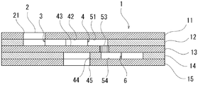
図1および図2のように、本実施の形態に係る分析器具は、第1プレート11と、第2プレート12と、第3プレート13と、第4プレート14と、第5プレート15とが、両面テープなどの接着層(図示なし)を介して接着されて構成されている。
As shown in FIGS. 1 and 2, the analytical instrument according to the present embodiment includes a
第1プレート11には貫通孔21が設けられており、試料供給口2を形成している。第2プレート12にも貫通孔21と略同心位置に貫通孔22が設けられ、貫通孔22からは溝31が延出している。溝31と第1プレート11および第3プレート13とで囲まれた領域が、試料供給口2から延出する第1の流路3を画成している。
The
第2プレート12の、貫通孔22から離隔した位置に、溝31と連通する貫通孔41が設けられている。第3プレート13には、貫通穴41と略同心位置に固定化抗体保持部43が設けられ、当該部に、分析対象物質に特異的に結合する抗体が固定される。また、第1プレート11には、貫通孔41と略同心位置に標識抗体保持部42が設けられ、当該部に、分析対象物質に特異的に結合する標識された抗体が遊離可能に保持される。貫通孔41と第1プレート11および第3プレート13とで囲まれた領域が反応室4を画成し、固定化抗体保持部43と標識抗体保持部42とは、反応室4を取り囲み対面する2つ壁面となる。なお、固定化抗体保持部43を第1プレート11に、標識抗体保持部42を第2プレート12に設けることも可能である。また、第1プレート11および第3プレート13のうち、少なくとも貫通孔41と略同心位置にある領域については、光透過性を有するよう構成されており、さらに、第4プレート14および第5プレート15には貫通孔41と略同心位置にそれぞれ貫通孔44,45が設けられている。反応後の反応室4における光学的変化量を測定する際に外部から反応室4まで光が到達するよう構成するためである。このとき、光透過性を有する部分の大きさを貫通孔41の大きさより小さく制限することによって、反応室4に入射される光束を制限することができるため好適である。開孔が設けられた光透過性を有さない膜を第1プレート11および第3プレート13に貼着したり、光透過性を付与する領域の周囲に光透過性を有さない塗料を塗布することなどによって、光透過性を有する部分の大きさを制限することができる。
A through
第2プレート12の貫通孔41からは溝511が延出し、端部511aまで延びている。第3プレート13には、端部511aを投影した位置と略同一位置に保持孔52が板厚方向に貫通して設けられており、保持孔52には閉塞部材53が収容されている。第4プレート14には、保持孔52を投影した位置と略同一位置に端部541aを有する溝541が設けられている。溝511と第1プレート11および第3プレート13とで囲まれた領域が、反応室4から連通する第2の流路5のうち、上流部51を画成しており、溝541と第3プレート13および第5プレート15とで囲まれた領域が、第2の流路5のうち下流部54を画成している。また、保持孔52は上流部51および下流部54と連通しており、すなわち、上流部51と保持孔52と下流部54とが第2の流路5を構成し、閉塞部材53が第2の流路5を閉塞するよう設けられている。
A
第4プレート14には、溝541と連通する貫通孔61が設けられており、貫通孔61と第3プレート13および第5プレート15とで囲まれた領域が廃液室6を画成している。
The
第1プレート11、第3プレート13および第5プレート15は不通気性でありかつ不通水性であり、材質としては、ポリエチレンテレフタレート(PET)やAS樹脂のようなプラスチック材料が、加工が容易であるため好適である。しかし、試料が漏出することがない流路を形成することができれば、これに限定されるものではない。また、第1プレート11および第3プレート13のうち、少なくとも貫通孔41と略同心位置にある領域については、光透過性を有するよう構成されている。反応後の反応室4における光学的変化量を測定するためである。
The
第2プレート12および第4プレート14には、不通水性で通気性のある多孔質材が用いられる。孔および溝の加工が容易であり、廃液室6の壁面から空気が逃げるため、空気抜き孔等を設けることなく試料を廃液室6まで移送することが可能となるからである。不通水性で通気性のある多孔質材として、ポリテトラフルオロエチレン(PTFE)や、撥水処理を施したセルロースアセテートおよびセルロース混合エステルなどが、好適に使用される。なお、試料が廃液室6に到達するために外部に放出される必要がある流路内の空気は全て、廃液室6から抜くことが可能であるため、第2プレート12について不通気性でありかつ不通水性の材料を用いることも可能である。また、廃液室6の壁面から外部に連通する空気抜き孔を設けることもでき、その場合第4プレート14に不通気性でありかつ不通水性の材料を用いることも可能となる。
The
閉塞部材53には、所定の圧力より低い圧力では通水せず、所定の圧力以上の圧力で通水する材料が用いられる。具体的には、セルロースアセテートおよびセルロース混合エステルなどの多孔質材に撥水処理を施したものが適用可能である。このとき、多孔質材の孔径が小さいと通水可能となる圧力が上昇し、試料が閉塞部材53を通水する前に第2プレート12に浸透するおそれが生じる。そのため、第2プレート12に用いる多孔質材の孔径より大きい孔径の多孔質材を選択することによって、第1の流路3、反応室4および第2の流路5の上流部51の壁面から試料が第2プレート12の内部に浸透する前に、閉塞部材53を通水して廃液室6まで試料を移送することが可能となる。具体的には、第2プレート12に用いる多孔質材の孔径を3μm以下、好ましくは1μm以下とする一方で、閉塞部材53に用いる多孔質材の孔径をそれより大きくすることが好ましい。なお、第2プレート12に施す撥水処理を閉塞部材53に施す撥水処理より強くすることによっても、上記と同等な効果を得ることができる。また、第2プレート12を不通気性でありかつ不通水性の材料で構成すると、試料が廃液室に進行する前に第2プレート12に浸透するおそれは生じない。
The closing
図4に反応室4の断面模式図を示す。第3プレート13の固定化抗体保持部43には、分析対象物質に特異的に結合する抗体が固定され、固定化抗体431が形成される。本実施形態においては、例えば抗ヘモグロビン抗体としてのモノクローナル抗体やポリクローナル抗体が使用され、物理吸着(ファンデルワールス結合)、疎水結合、化学結合などの一般的手法で固定化抗体保持部43に固定される。なお、ここに記載する「ヘモグロビン」とは、糖化ヘモグロビンおよび未糖化ヘモグロビンの両方を含む。
FIG. 4 shows a schematic cross-sectional view of the
第1プレート11の標識抗体保持部42には、分析対象物質に特異的に結合する、標識された標識抗体421が遊離可能に保持されている。本実施形態においては、例えば蛍光色素などで化学結合により標識された抗糖化ヘモグロビンモノクローナル抗体が適切な可溶性保持体422を介して当該部に塗布されている。標識の蛍光色素としては、フルオレセインイソチオシアネート(FITC)、ローダミン、1−ジメチルアミノナフタレン5−スルホニルクロリド(DANS)などが用いられる。蛍光色素以外には、青色ラテックス粒子などの着色粒子を標識物質として使用することができる。また、可溶性保持体422は任意であるが、スクロース、ソルビトール、トレハロースなどの多糖類の溶液を塗布・乾燥させたものが好適に使用される。
The labeled
次に、本実施の形態に係る器具を用いた分析の手順および器具の作用について説明する。 Next, the analysis procedure using the instrument according to the present embodiment and the function of the instrument will be described.
赤血球を希釈・溶血した試料を試料供給口2に滴下する。希釈・溶血操作は、一般的にはサポニンなどの界面活性剤を含む溶液を用い、検出の際の光学的変化量を考慮した適度な希釈倍率で行われる。試料を滴下した後、試料供給口2を所定の圧力より低い圧力で加圧する。ここで「所定の圧力」とは、閉塞部材53が通水する圧力である。なお、ここで加える圧は、反応が終了するまで加圧した状態を維持したままでもよいし、試料が反応室4に到達した後に一旦解除し、さらに後の工程で再加圧する方法を用いてもよい。
A sample diluted with red blood cells and hemolyzed is dropped into the
このとき閉塞部材53は通気性を有しつつ不通水性を有し、また廃液室6の壁面も通気性を有するため、試料は第1の流路3を通り反応室4まで到達する。第2の流路5は閉塞部材53によってせき止められているため、試料はそれ以上は進行せず、反応室4にとどまる。この状態での反応室4の断面模式図を図5に示す。
At this time, since the blocking
反応室4において、試料に含まれる分析対象物質である未糖化ヘモグロビン82と糖化ヘモグロビン81とは、その構成比に比例した割合で固定化抗体保持部43に備えられた固定化抗体431に特異的に結合する。一方、標識抗体保持部42に備えられた標識抗体421は、試料に溶かされ遊動を開始し、試料に含有される糖化ヘモグロビン81のみと抗原抗体反応を開始する。ここで反応が完了するまで待機する。すると、試料中の未糖化ヘモグロビン82と糖化ヘモグロビン81の構成比に比例した割合で、固定化抗体431−未糖化ヘモグロビン82の複合体と、固定化抗体431−糖化ヘモグロビン81−標識抗体421の複合体とが、固定化抗体保持部43に形成される。なお、この結合反応が完了した後でも、試料の中には未反応の標識抗体421が多量に含まれている。この状態での反応室4の断面模式図を図6に示す。
In the
反応室4での反応が完了するのに必要な時間が経過したあと、試料供給口2を所定の圧力以上の圧力で加圧する。閉塞部材53に所定の圧力以上の圧力が加えられると通水を開始するため、試料は廃液室6に移送される。このとき、前記の複合体形成に使用されなかった試料中の未反応の標識抗体421は、試料とともに廃液室6に移送されることとなる。すなわち、別途洗浄液を注入することなく反応室4の手前に余剰に存在する試料によるB/F分離が行われることになる。この状態での反応室4の断面模式図を図7に示す。なお、本実施形態では、試料が閉塞部材53の厚さ方向に進行するよう構成されているため、閉塞部53および第3プレート13の厚さを適宜に設定することによって通水するために必要な圧力を変更することができる。また、微小に成形された流路に大きさを合わせる必要がないため、閉塞部材53は容易に成形することが可能である。
After the time necessary for completing the reaction in the
試料が廃液室6に移送された後、例えば標識物質が蛍光色素の場合では、反応室4の蛍光強度を光学的に計測することにより、固定化抗体保持部43に捕捉された糖化ヘモグロビン81の量を定量的に測定することができる。また、標識物質が青色ラテックス粒子などの着色粒子の場合では、反応室4の吸光度や反射率を測定することにより、固定化抗体保持部43に捕捉された糖化ヘモグロビン81の量を定量的に測定することができる。糖化ヘモグロビン測定の場合は、全ヘモグロビン中の糖化ヘモグロビン割合(百分率)で表記することが一般的であるが、本法によれば、反応室4の単位面積における抗ヘモグロビン抗体の固定化量を一定にしておくことにより、ここに結合するヘモグロビン量も一定となることから、複合体を形成した糖化ヘモグロビン量に依存する蛍光強度を計測することだけで、全ヘモグロビン中の糖化ヘモグロビン割合(百分率)を得ることができる。
After the sample is transferred to the
本実施の形態は、糖化ヘモグロビンを測定するための器具として構成しているため、試料として溶血したものを供給する形態としているが、全血を供給して器具の試料供給口と反応室との間に溶血手段を設けることによって、全血の試料を供給して糖化ヘモグロビンを測定するように構成することも可能である。 Since this embodiment is configured as an instrument for measuring glycated hemoglobin, it is configured to supply a hemolyzed sample as a sample. However, whole blood is supplied and the sample supply port of the instrument and the reaction chamber are connected. It is also possible to provide a hemolysis means between them to supply a whole blood sample and measure glycated hemoglobin.
また、固定化抗体および標識抗体を適宜選択することによって、分析対象物質をCEA、AFP等の腫瘍マーカーとすることも可能である。その際は試料として血漿を供給することが好適であるが、図8に示すように、供給口保持体25に設けられた試料供給口2と反応室4との間に血球成分を分離する濾過手段23を設けることによって、試料として全血を供給し、試料の中に含有される腫瘍マーカーを測定することも可能となる。さらにこの場合、図8に示すように、濾過手段23と反応室4との間に、血漿を蓄えるための血漿貯留室24を設けると、抗原抗体反応が完了した後、血漿貯留室24に貯留された余剰試料を用いて未反応の標識抗体421を反応室4から廃液室6に移送することができるため、好適である。
In addition, the analysis target substance can be used as a tumor marker such as CEA or AFP by appropriately selecting an immobilized antibody and a labeled antibody. In that case, it is preferable to supply plasma as a sample. However, as shown in FIG. 8, filtration for separating blood cell components between the
(第2の実施形態)
図9に、本発明の第2の実施形態に係る体液成分の分析器具100について、分解斜視図を示す。以下においては、第1の実施形態との相違点を中心に説明し、対応する箇所には同一の符号を付して説明する。(Second Embodiment)
FIG. 9 is an exploded perspective view of the body fluid
本実施の形態は、第1の実施形態と同様に、赤血球を溶血した試料をもとに糖化ヘモグロビンを測定するための形態となっている。第1の実施形態との主たる相違点として、第1の実施形態に係る体液成分の分析器具が計5枚のプレートから構成されているのに対して、本実施形態では、第1プレート11、第2プレート12および第3プレート13の、計3枚のプレートから構成されている点が挙げられる。第1プレート11の構成は第1の実施形態と同様である。第2プレート12には、第1の実施形態と同様に貫通孔22、貫通孔から延出する溝31、溝31と連通する貫通孔41、貫通孔41から延出する溝511が設けられているとともに、溝511に連通する貫通孔61が設けられている。また、貫通孔41と貫通孔61との間には、溝511を閉塞するように閉塞部材53が設けられている。第3プレート13には、第1の実施形態と同様に固定化抗体保持部43が設けられているが、貫通孔は設けられていない。体液成分の分析器具100が組み立てられたとき、貫通孔41と第1プレート11および第3プレート13とで囲まれた領域が反応室4を画成し、貫通孔61と第1プレート11および第3プレート13とで囲まれた領域が廃液室6を画成する。また、溝31と第1プレート11および第3プレート13とで囲まれた領域が第1の流路3を画成し、溝511と第1プレート11および第3プレート13とで囲まれた領域が第2の流路5を画成する。なお、固定化抗体保持部43に配置されている固定化抗体431、および標識抗体保持部43に保持されている標識抗体421も、第1の実施形態と同様である。
As in the first embodiment, the present embodiment is a mode for measuring glycated hemoglobin based on a sample obtained by hemolyzing red blood cells. As a main difference from the first embodiment, the body fluid component analysis instrument according to the first embodiment is composed of a total of five plates, whereas in the present embodiment, the
本実施形態においても、第1の実施形態と同様に閉塞部材53は第2の流路5を閉塞するよう構成されているが、第1の実施形態に係る体液成分の分析器具1は、第2の流路5が閉塞部材53を挟んで上下のプレートに分かれて配置されているのに対して、本実施形態に係る体液成分の分析器具100では、第2の流路5の全体と、閉塞部材53と、廃液室6とが、1つのプレート(第2プレート12)内に収められている。
Also in this embodiment, the closing
第1プレート11および第3プレート13は不通気性でありかつ不通水性の材料が用いられ、少なくとも貫通孔41と略同心位置にある領域については光透過性を有するよう構成されていることは、第1の実施形態と同様である。また、第2プレート12には、試料の浸透を防止しつつ廃液室6から空気を逃がすため、不通水性で通気性のある多孔質材が用いられるが、廃液室6に空気孔などを設けることによって、不通気性でありかつ不通水性の材料を適用することも可能である。
The
本実施の形態に係る体液成分の分析器具100を用いた分析の手順および器具の作用は、第1の実施の形態と全く同様である。
The analysis procedure using the body fluid
1 体液成分の分析器具
11 第1プレート
12 第2プレート
13 第3プレート
14 第4プレート
15 第5プレート
100 体液成分の分析器具
2 試料供給口
21 貫通孔
22 貫通孔
23 濾過手段
24 血漿貯留室
25 供給口保持体
3 第1の流路
31 溝
4 反応室
41 貫通孔
42 標識抗体保持部
421 標識抗体
422 可溶性保持体
43 固定化抗体保持部
431 固定化抗体
44 貫通孔
45 貫通孔
5 第2の流路
51 上流部
511 溝
511a 端部
52 保持孔
53 閉塞部材
54 下流部
541 溝
541a 端部
6 廃液室
61 貫通孔
81 糖化ヘモグロビン
82 未糖化ヘモグロビンDESCRIPTION OF
Claims (5)
前記試料供給口から延出する第1の流路と、
前記第1の流路に連通する反応室と、
前記反応室から延出する第2の流路と、
前記第2の流路に連通する廃液室と、
前記第2の流路を閉塞するよう設けられた閉塞部材とを備え、
前記閉塞部材は、通気性を有するとともに、所定の圧力より低い圧では通水せず、前記所定の圧力以上の圧力で通水し、
前記反応室を取り囲み対面する2つの壁面が光透過性を有し、
前記2つの壁面のいずれか一方に前記試料に含まれる分析対象物質と特異的に結合する抗体が固定化されており、
さらに前記反応室に前記分析対象物質と特異的に結合する標識された抗体が遊離可能に保持されており、
前記廃液室を取り囲む壁面の少なくとも一部が通気性を有する
ことを特徴とする体液成分の分析器具。A sample supply port through which a sample is supplied;
A first flow path extending from the sample supply port;
A reaction chamber communicating with the first flow path;
A second flow path extending from the reaction chamber;
A waste liquid chamber communicating with the second flow path;
A closing member provided to close the second flow path,
The closing member has air permeability and does not pass water at a pressure lower than a predetermined pressure, and passes water at a pressure equal to or higher than the predetermined pressure.
Two wall surfaces surrounding the reaction chamber and facing each other are light transmissive,
An antibody that specifically binds to the analyte contained in the sample is immobilized on either one of the two wall surfaces,
Furthermore, a labeled antibody that specifically binds to the analyte is held in the reaction chamber in a releasable manner,
A body fluid component analysis instrument, wherein at least a part of a wall surface surrounding the waste liquid chamber has air permeability.
ことを特徴とする請求項1に記載の体液成分の分析器具。The body fluid component analysis instrument according to claim 1, wherein the closing member is made of a porous material subjected to a water repellent treatment.
前記保持プレートに、前記第2の流路の一部を構成する貫通孔が、板厚方向に貫通して設けられており、
前記貫通孔に前記閉塞部材が収容されており、
前記第2の流路のうち前記反応室と前記貫通孔とを連通する上流部分が、前記保持プレートの一の面側に配置されており、
前記第2の流路のうち前記貫通孔と前記廃液室とを連通する下流部分が、前記保持プレートの他の面側に配置されている
ことを特徴とする請求項1または2に記載の体液成分の分析器具。Equipped with an impermeable and impermeable retaining plate,
The holding plate is provided with a through hole that constitutes a part of the second flow path in the thickness direction,
The closing member is accommodated in the through hole,
An upstream portion communicating the reaction chamber and the through hole in the second flow path is disposed on one surface side of the holding plate,
The bodily fluid according to claim 1 or 2, wherein a downstream portion of the second flow path that communicates the through hole and the waste liquid chamber is disposed on the other surface side of the holding plate. Component analysis instrument.
ことを特徴とする請求項1〜3のいずれかに記載の体液成分の分析器具。The waste liquid chamber is formed by laminating a water-permeable and air-permeable ventilation plate and a gas-permeable and water-impermeable sealing plate. 2. The body fluid component analyzing instrument according to 1.
試料を前記試料供給口に供給する工程と、
前記所定の圧力より低い第1の圧力を前記使用供給口に与えて前記試料を前記反応室に移送する工程と、
所定の時間が経過した後、前記所定の圧力以上の第2の圧力を前記試料供給口に与えて前記試料を前記廃液室に移送する工程と、
前記反応室の光学的変化量を測定する工程とを備える
ことを特徴とする体液成分の分析方法。Using the body fluid component analysis instrument according to any one of claims 1 to 4,
Supplying a sample to the sample supply port;
Applying a first pressure lower than the predetermined pressure to the use supply port to transfer the sample to the reaction chamber;
After a predetermined time has elapsed, transferring the sample to the waste liquid chamber by applying a second pressure equal to or higher than the predetermined pressure to the sample supply port;
And a step of measuring an optical change amount in the reaction chamber.
Applications Claiming Priority (1)
| Application Number | Priority Date | Filing Date | Title |
|---|---|---|---|
| PCT/JP2009/057466 WO2010119501A1 (en) | 2009-04-13 | 2009-04-13 | Bodily fluid component analyzer |
Publications (2)
| Publication Number | Publication Date |
|---|---|
| JPWO2010119501A1 JPWO2010119501A1 (en) | 2012-10-22 |
| JP5339552B2 true JP5339552B2 (en) | 2013-11-13 |
Family
ID=42982185
Family Applications (1)
| Application Number | Title | Priority Date | Filing Date |
|---|---|---|---|
| JP2011509102A Expired - Fee Related JP5339552B2 (en) | 2009-04-13 | 2009-04-13 | Body fluid component analyzer |
Country Status (2)
| Country | Link |
|---|---|
| JP (1) | JP5339552B2 (en) |
| WO (1) | WO2010119501A1 (en) |
Citations (3)
| Publication number | Priority date | Publication date | Assignee | Title |
|---|---|---|---|---|
| JP2003254896A (en) * | 2002-02-28 | 2003-09-10 | Kokusai Gijutsu Kaihatsu Co Ltd | Sample cartridge, sample analyzer and method |
| JP2008539419A (en) * | 2005-04-30 | 2008-11-13 | シェーン ユウ、ジャエ | Biodisc and biodriver device, and analysis method using the same |
| WO2009034649A1 (en) * | 2007-09-14 | 2009-03-19 | Ttm Co., Ltd. | Liquid fluid testing instrument and testing method |
-
2009
- 2009-04-13 JP JP2011509102A patent/JP5339552B2/en not_active Expired - Fee Related
- 2009-04-13 WO PCT/JP2009/057466 patent/WO2010119501A1/en not_active Ceased
Patent Citations (3)
| Publication number | Priority date | Publication date | Assignee | Title |
|---|---|---|---|---|
| JP2003254896A (en) * | 2002-02-28 | 2003-09-10 | Kokusai Gijutsu Kaihatsu Co Ltd | Sample cartridge, sample analyzer and method |
| JP2008539419A (en) * | 2005-04-30 | 2008-11-13 | シェーン ユウ、ジャエ | Biodisc and biodriver device, and analysis method using the same |
| WO2009034649A1 (en) * | 2007-09-14 | 2009-03-19 | Ttm Co., Ltd. | Liquid fluid testing instrument and testing method |
Also Published As
| Publication number | Publication date |
|---|---|
| WO2010119501A1 (en) | 2010-10-21 |
| JPWO2010119501A1 (en) | 2012-10-22 |
Similar Documents
| Publication | Publication Date | Title |
|---|---|---|
| US20080213133A1 (en) | Flow analysis apparatus and method | |
| JP6037184B2 (en) | Assay device using porous media | |
| EP1776574B1 (en) | Mechanical cartridge with test strip fluid control features for use in a fluid analyte meter | |
| JP3553045B2 (en) | Biosensor | |
| CN202886374U (en) | Device for carrying out multiple tests | |
| EP2285491A1 (en) | Flow control in microfluidic systems | |
| TWI498166B (en) | Porous membrane based autonormous handling process microfluidic device for surface plasmon resonance quantitative analysis | |
| JPWO2001090754A1 (en) | Biosensors | |
| WO2009068583A2 (en) | Separation and detection device with means for optimization of the capillary drag force | |
| CN211905402U (en) | Detection chip and detection system | |
| US20210055284A1 (en) | Microchip immunoassay device having precise incubation time control and signal scaling and related methods | |
| JP6779433B2 (en) | Detection device and detection method | |
| CN105445454A (en) | Quantifiable immunochromatography device | |
| EP4006553A1 (en) | Blood group antigen testing component | |
| CN211014324U (en) | Detection chip and detection system | |
| JP5339552B2 (en) | Body fluid component analyzer | |
| WO2006080438A1 (en) | Immunochromatographic test instrument and semiquantitative method using the same | |
| EP4071463B1 (en) | Reaction test paper, detection chip and detection system | |
| JP5224276B2 (en) | Body fluid component analyzer | |
| CN212989175U (en) | Composite detection chip | |
| CN112088308A (en) | Microchip having three-dimensional structure of paper base for detecting target antigen using immunochemical diagnostic method and target antigen detecting method using the same | |
| US20240157355A1 (en) | Interface to lateral flow | |
| EP1717585A1 (en) | Microchip and analysis method using the same | |
| JP6043990B2 (en) | Body fluid sample transfer mechanism, body fluid sample transfer method, body fluid component analyzer, and body fluid component analysis method | |
| JP7337371B2 (en) | Immunochromatography measurement device |
Legal Events
| Date | Code | Title | Description |
|---|---|---|---|
| TRDD | Decision of grant or rejection written | ||
| A01 | Written decision to grant a patent or to grant a registration (utility model) |
Free format text: JAPANESE INTERMEDIATE CODE: A01 Effective date: 20130716 |
|
| A61 | First payment of annual fees (during grant procedure) |
Free format text: JAPANESE INTERMEDIATE CODE: A61 Effective date: 20130802 |
|
| R150 | Certificate of patent or registration of utility model |
Ref document number: 5339552 Country of ref document: JP Free format text: JAPANESE INTERMEDIATE CODE: R150 Free format text: JAPANESE INTERMEDIATE CODE: R150 |
|
| R250 | Receipt of annual fees |
Free format text: JAPANESE INTERMEDIATE CODE: R250 |
|
| S111 | Request for change of ownership or part of ownership |
Free format text: JAPANESE INTERMEDIATE CODE: R313117 |
|
| R350 | Written notification of registration of transfer |
Free format text: JAPANESE INTERMEDIATE CODE: R350 |
|
| R250 | Receipt of annual fees |
Free format text: JAPANESE INTERMEDIATE CODE: R250 |
|
| R250 | Receipt of annual fees |
Free format text: JAPANESE INTERMEDIATE CODE: R250 |
|
| R250 | Receipt of annual fees |
Free format text: JAPANESE INTERMEDIATE CODE: R250 |
|
| R250 | Receipt of annual fees |
Free format text: JAPANESE INTERMEDIATE CODE: R250 |
|
| R250 | Receipt of annual fees |
Free format text: JAPANESE INTERMEDIATE CODE: R250 |
|
| LAPS | Cancellation because of no payment of annual fees |