JP5336285B2 - Stereoscopic image display apparatus, method and program, and imaging apparatus - Google Patents
Stereoscopic image display apparatus, method and program, and imaging apparatus Download PDFInfo
- Publication number
- JP5336285B2 JP5336285B2 JP2009170252A JP2009170252A JP5336285B2 JP 5336285 B2 JP5336285 B2 JP 5336285B2 JP 2009170252 A JP2009170252 A JP 2009170252A JP 2009170252 A JP2009170252 A JP 2009170252A JP 5336285 B2 JP5336285 B2 JP 5336285B2
- Authority
- JP
- Japan
- Prior art keywords
- image
- reference viewpoint
- predetermined
- display
- viewpoint image
- Prior art date
- Legal status (The legal status is an assumption and is not a legal conclusion. Google has not performed a legal analysis and makes no representation as to the accuracy of the status listed.)
- Expired - Fee Related
Links
Images


Classifications
-
- H—ELECTRICITY
- H04—ELECTRIC COMMUNICATION TECHNIQUE
- H04N—PICTORIAL COMMUNICATION, e.g. TELEVISION
- H04N13/00—Stereoscopic video systems; Multi-view video systems; Details thereof
- H04N13/30—Image reproducers
- H04N13/356—Image reproducers having separate monoscopic and stereoscopic modes
- H04N13/359—Switching between monoscopic and stereoscopic modes
-
- H—ELECTRICITY
- H04—ELECTRIC COMMUNICATION TECHNIQUE
- H04N—PICTORIAL COMMUNICATION, e.g. TELEVISION
- H04N13/00—Stereoscopic video systems; Multi-view video systems; Details thereof
- H04N13/10—Processing, recording or transmission of stereoscopic or multi-view image signals
- H04N13/106—Processing image signals
- H04N13/144—Processing image signals for flicker reduction
-
- H—ELECTRICITY
- H04—ELECTRIC COMMUNICATION TECHNIQUE
- H04N—PICTORIAL COMMUNICATION, e.g. TELEVISION
- H04N13/00—Stereoscopic video systems; Multi-view video systems; Details thereof
- H04N13/10—Processing, recording or transmission of stereoscopic or multi-view image signals
- H04N13/189—Recording image signals; Reproducing recorded image signals
-
- H—ELECTRICITY
- H04—ELECTRIC COMMUNICATION TECHNIQUE
- H04N—PICTORIAL COMMUNICATION, e.g. TELEVISION
- H04N13/00—Stereoscopic video systems; Multi-view video systems; Details thereof
- H04N13/30—Image reproducers
- H04N13/302—Image reproducers for viewing without the aid of special glasses, i.e. using autostereoscopic displays
- H04N13/31—Image reproducers for viewing without the aid of special glasses, i.e. using autostereoscopic displays using parallax barriers
-
- H—ELECTRICITY
- H04—ELECTRIC COMMUNICATION TECHNIQUE
- H04N—PICTORIAL COMMUNICATION, e.g. TELEVISION
- H04N2213/00—Details of stereoscopic systems
- H04N2213/002—Eyestrain reduction by processing stereoscopic signals or controlling stereoscopic devices
Landscapes
- Engineering & Computer Science (AREA)
- Multimedia (AREA)
- Signal Processing (AREA)
- Testing, Inspecting, Measuring Of Stereoscopic Televisions And Televisions (AREA)
- Controls And Circuits For Display Device (AREA)
- Apparatus For Radiation Diagnosis (AREA)
Description
本発明は、視差を有する複数の視点画像に基づいて立体表示を行う装置に関する。 The present invention relates to an apparatus that performs stereoscopic display based on a plurality of viewpoint images having parallax.
3D画像を表示する際に、目の疲労軽減のため3D画像を2D表示した後に3D表示に切り換える技術がある。例えば特許文献1によると、視差量計算手段は左右画像の視差量を計算し、視差量決定手段は視差量の変化の様子を監視し、視差量が大きく変化したような場合、あるいは2次元画像から3次元画像に切り換わったような場合に、画像制御手段に与える視差量を制御して、急激な変化を抑圧し、自然な切り換わりを実現する。 When displaying a 3D image, there is a technique for switching to 3D display after displaying the 3D image in 2D to reduce eye fatigue. For example, according to Patent Document 1, the parallax amount calculating unit calculates the parallax amount of the left and right images, and the parallax amount determining unit monitors the change of the parallax amount, and when the parallax amount changes greatly, or a two-dimensional image When switching from a 3D image to a 3D image, the parallax amount given to the image control means is controlled to suppress a sudden change and realize a natural switching.
ユーザは、撮影した画像を2D表示して、この画像の中から目的とする画像を見つけた後、当該画像を2D表示から3D表示に即座に切り換えたい場合がある。本発明は、必要に応じて画像を2D表示から3D表示に即座に切り換えることを目的とする。 There are cases where the user wants to immediately switch the captured image from 2D display to 3D display after displaying the captured image in 2D and finding a target image from the images. An object of the present invention is to immediately switch an image from 2D display to 3D display as necessary.
本発明は、複数の視点画像を所定の記憶媒体に入力する画像入力部と、前記所定の記憶媒体に入力された複数の視点画像に基づいて所定の表示装置に立体画像を表示することが可能な表示制御部と、を備え、前記表示制御部は、平面画像終了の指示が入力されるまで、前記複数の視点画像のうち所望の基準視点画像に基づいて所定の表示装置に平面画像を表示するとともに、前記平面画像終了の指示が入力されたことに応じて所定の表示装置に前記立体画像を表示する立体画像表示装置を提供する。 The present invention is capable of displaying a stereoscopic image on a predetermined display device based on an image input unit that inputs a plurality of viewpoint images to a predetermined storage medium and the plurality of viewpoint images input to the predetermined storage medium. A display control unit, and the display control unit displays a planar image on a predetermined display device based on a desired reference viewpoint image among the plurality of viewpoint images until an instruction to end the planar image is input. In addition, a stereoscopic image display device that displays the stereoscopic image on a predetermined display device in response to the input of the instruction to end the planar image is provided.
好ましくは、前記表示制御部は、前記平面画像終了の指示が入力されないまま所定の第1の待機時間が経過したことに応じて前記表示装置に前記立体画像を表示する。 Preferably, the display control unit displays the stereoscopic image on the display device in response to the elapse of a predetermined first waiting time without inputting an instruction to end the planar image.
好ましくは、前記表示制御部は、ずらし表示終了の指示が入力されるまで、前記基準視点画像および前記基準視点画像以外の視点画像である非基準視点画像の視差量を所定量ずつずらして前記表示装置に立体画像を表示することを繰り返す。 Preferably, the display control unit shifts the parallax amount of the non-reference viewpoint image that is a viewpoint image other than the reference viewpoint image and the reference viewpoint image by a predetermined amount until an instruction to end the shift display is input. Repeat displaying a stereoscopic image on the device.
好ましくは、前記表示制御部は、ずらし表示終了の指示が入力されるまで、前記基準視点画像および前記非基準視点画像の視差量を所定量ずつずらして前記表示装置に立体画像を表示することを、前記基準視点画像および前記非基準視点画像の視差量が所定の目標視差量に適合するまで繰り返す。 Preferably, the display control unit displays a stereoscopic image on the display device by shifting a parallax amount between the reference viewpoint image and the non-reference viewpoint image by a predetermined amount until a shift display end instruction is input. The process is repeated until the parallax amounts of the reference viewpoint image and the non-reference viewpoint image match a predetermined target parallax amount.
好ましくは、前記画像入力部は、前記立体画像が表示された状態で立体画像終了指示が入力されないまま所定の第2の待機時間が経過したことに応じ、前記記憶媒体から既存の視点画像を消去し、前記記憶媒体に新たな複数の視点画像を入力する。 Preferably, the image input unit erases an existing viewpoint image from the storage medium in response to a predetermined second waiting time having elapsed without displaying a stereoscopic image end instruction in a state where the stereoscopic image is displayed. Then, a plurality of new viewpoint images are input to the storage medium.
本発明は、立体画像表示装置または撮像装置が、複数の視点画像を所定の記憶媒体に入力するステップと、平面画像終了の指示が入力されるまで、複数の視点画像のうち所望の基準視点画像に基づいて所定の表示装置に平面画像を表示するとともに、前記平面画像終了の指示が入力されたことに応じて、前記複数の視点画像に基づいて立体画像を所定の表示装置に表示するステップと、を実行する立体画像表示方法を提供する。 The present invention relates to a step in which a stereoscopic image display device or an imaging device inputs a plurality of viewpoint images to a predetermined storage medium and a desired reference viewpoint image among a plurality of viewpoint images until an instruction to end a planar image is input. Displaying a planar image on a predetermined display device based on the image, and displaying a stereoscopic image on the predetermined display device based on the plurality of viewpoint images in response to the input of the instruction to end the planar image. A stereoscopic image display method for executing is provided.
この立体画像表示方法を立体画像表示装置や撮像装置に実行させるためのプログラムも本発明に含まれる。また、本発明は、上記の立体画像表示装置と、複数の光学系の各々を介して結像した被写体像を撮像素子により光電変換して得られた複数の視点画像を、前記立体画像表示装置の画像入力部に入力する撮像部と、を備えた撮像装置を提供する。 A program for causing a stereoscopic image display apparatus or an imaging apparatus to execute this stereoscopic image display method is also included in the present invention. In addition, the present invention provides the above-described stereoscopic image display device, and a plurality of viewpoint images obtained by photoelectrically converting a subject image formed through each of a plurality of optical systems using an imaging device. And an imaging unit that inputs to the image input unit.
この発明によると、一旦画像を2D表示して指示があった場合に3D表示に切り換えることで、観察者の目の疲労の軽減と3D表示への切り換えの高速化を同時に実現できる。 According to the present invention, once an image is displayed in 2D and switched to 3D display when an instruction is given, it is possible to simultaneously reduce eye fatigue of the observer and increase the speed of switching to 3D display.
<第1実施形態>
以下、添付図面を参照し、本発明の好ましい実施形態に係るカメラ2を説明する。
<First Embodiment>
Hereinafter, a camera 2 according to a preferred embodiment of the present invention will be described with reference to the accompanying drawings.
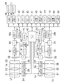
図1は、カメラ2の電気的構成を示す。第1撮影光学系1aは、レンズ光軸L1に沿って配列された、第1変倍レンズ21、第1フォーカスレンズ22、第1絞り23によって構成されている。第1変倍レンズ21は、直流モータおよびドライバで構成された第1変倍レンズ制御部24によって駆動される。第1フォーカスレンズ22は、直流モータおよびドライバで構成された第1フォーカスレンズ制御部25によって駆動される。第1絞り23は直流モータおよびドライバで構成された第1絞り制御部26によって駆動される。制御部24〜26の動作はメインCPU40(以下単にCPU40で表す)によって制御される。
FIG. 1 shows the electrical configuration of the camera 2. The first photographing
第1変倍レンズ制御部24は、操作部10のズームボタン(ただしボタンでなくリング状操作部材も可)へのテレまたはワイドのズーム方向情報の入力操作に応じて、第1変倍レンズ21をホームポジションを起点にレンズ光軸L1に沿ってテレ側(繰り出し側)/ワイド側(繰り込み側)に移動させ、焦点距離(撮影倍率)を変化させる。第1変倍レンズ21をテレ側に移動させると、長焦点となり撮影範囲は狭くなる。第1変倍レンズ21をワイド側に移動させると、短焦点となり撮影範囲は広くなる。
The first variable magnification
フォーカスレンズ制御部25は、第1フォーカスレンズ22をレンズ光軸L1に沿って移動させ、ピント調整を行う。第1フォーカスレンズ22は、第1変倍レンズ21の移動に伴って、ピントがズレないように自動的に位置が調整されるようになっている。操作部10からは、段階的なズーム倍率(ズーム段)Z1、Z2・・・、Znが入力可能であるとする。その段階の数nは任意であるが、Z1はワイド端、Znはテレ端に対応する。
The focus
CPU40には、ズームボタンから設定された目標ズーム方向が出力される。CPU40は、当該目標ズーム方向に従い、目標ズーム位置を設定する。目標ズーム方向がテレ方向であれば現在の第1変倍レンズ21の位置からテレ方向側にかけて最も近いズーム段を目標ズーム位置とし、目標ズーム方向がワイド方向であれば現在の第1変倍レンズ21からワイド方向側にかけて最も近いズーム段を目標ズーム位置とする。CPU40は、目標ズーム位置を第1変倍レンズ21の目標停止位置までのパルス数に換算し、第1変倍レンズ制御部24にそのパルス数に応じた駆動を行わせる。なお、パルス数0は、ホームポジションに対応する。
The target zoom direction set from the zoom button is output to the
第1イメージセンサ28は、第1変倍レンズ21及び第1フォーカスレンズ22によって結像された被写体光を受光し、受光量に応じた光電荷を受光素子に蓄積する。第1イメージセンサ28は、タイミングジェネレータ20(TG)から定期的に入力されるタイミング信号(クロックパルス)により光電荷蓄積・転送動作が制御され、撮影モード時には、1画面分の画像信号を所定周期ごとに取得し、順次、第1アナログ信号処理部27に入力する。なお、第1イメージセンサ28として、CCD型やMOS型の固体撮像装置が用いられる。
The
第1アナログ信号処理部27は、第1イメージセンサ28から入力された1画面分の撮像信号を受け、各受光素子の蓄積電荷量に正確に対応したR,G,Bの画像データを増幅して第1A/D変換器29に入力する。第1A/D変換器29は、入力された画像データをアナログからデジタルに変換する。第1イメージセンサ28の撮像信号は、第1アナログ信号処理部27、第1A/D変換器29を介して、第1画像データ(右眼用画像データ)となる。
The first analog
第2撮影光学系1bは、第1撮影光学系1aと同一の構成であり、第2変倍レンズ制御部34によって駆動される第2変倍レンズ31、第2フォーカスレンズ制御部36によって駆動される第2フォーカスレンズ32、第2絞り制御部37によって駆動される第2絞り38によって構成されている。各制御部34,36,37の動作はCPU40によって制御される。
The second photographing
なお、第2撮影光学系1bの各部材は、第1撮影光学系1aの各部材と同質のものが用いられている。また、第1撮影光学系1aと第2撮影光学系1bとは、基本的に同期が取られており、それぞれ連動して撮像動作を行うが、制御速度向上などの目的でそれぞれの撮影光学系を個別に動かしてもよい。
In addition, the same thing as each member of the 1st imaging
第2アナログ信号処理部35、第2A/D変換器39は、前述の第1アナログ信号処理部、A/D変換器29とそれぞれ同一の構成である。第2イメージセンサ33の撮像信号は、第2アナログ信号処理部35、第2A/D変換器39を介して、第2画像データ(左眼用画像データ)となる。
The second analog
第1・第2A/D変換器29,39から出力された第1及び第2画像データは、それぞれ画像入力コントローラ39a・39bを介してデジタル信号処理部41,42に入力される。デジタル信号処理部41,42は、階調変換、ホワイトバランス補正、γ補正処理などの各種画像処理を第1・2画像データの各々に施す。デジタル信号処理部41で処理されて所定周期ごとに出力された第1画像データは、VRAM43に入力される。デジタル信号処理部42で処理されて所定周期ごとに出力された第2画像データは、VRAM43に入力される。
The first and second image data output from the first and second A /
VRAM43は、第1及び第2画像データを一時的に格納する作業用メモリである。なお、VRAM43にすでに第1及び第2画像データが記憶された状態で次の周期の第1及び第2画像データがVRAM43に入力された場合、すでに記憶された第1及び第2画像データは新しく入力された第1及び第2画像データで上書きされる。VRAM43で所定周期ごとに繰り返し上書き更新される第1及び第2画像データのことをスルー画像と呼ぶ。
The
3D画像生成部45は、VRAM43に格納された第1及び第2画像データを、モニター11が立体表示を行うための立体画像データに合成する。表示制御部56は、撮影モード時においてモニター11が電子ビューファインダとして使用される際に、3D画像生成部45によって合成された立体画像データをモニター11にスルー画像として表示させる。
The 3D
撮影画像の記録について以下説明する。シャッタボタン6が押されたタイミングで第1撮影光学系1a、第2撮影光学系1bから取り込まれた画像は、それぞれアナログ信号処理部27、35で処理された後、A/D変換器29、39でデジタル信号に変換され、それぞれ画像入力コントローラ39a・39bを介してデジタル信号処理部41,42に入力される。デジタル信号処理部41,42は、階調変換、ホワイトバランス補正、γ補正処理などの各種画像処理を第1・2画像データの各々に施す。デジタル信号処理部41、42で処理されて出力された第1・2画像データは、SDRAM52に記録される。圧縮伸張処理部47は、記憶された第1及び第2画像データに対して、JPEG方式等の圧縮形式により圧縮処理を施す。SDRAM52は、この圧縮処理に必要な一時的記憶領域として用いられる。メディア制御部48は、圧縮伸張処理部47によって圧縮処理された各画像データを格納した画像ファイルをメモリカード49に記録させる。なお、CPU40は操作部10から3D画像撮影モードが選択された場合に限り、第1・2画像データを取得するよう第1撮影光学系1a、第2撮影光学系1bその他の各部を制御してもよい。
The recording of the captured image will be described below. Images taken from the first photographing
このようにしてメモリカード49に記録された第1及び第2画像データをモニター11に再生表示させる場合、メモリカード49に記録された各画像データは、メディア制御部48によって読み出される。圧縮伸張処理部47によって伸張処理が行われた各画像データは、3D画像生成部45によって立体画像データに変換された後、表示制御部56を介してモニター11に再生表示される。
When the first and second image data recorded on the
図2に示すように、モニター11は、その表面にパララックスバリア表示層を備えている。モニター11は、パララックスバリア表示層に光透過部と光遮蔽部とが交互に所定のピッチで並んだパターンからなるパララックスバリア11aを発生させる。かつモニター11は、パララックスバリア表示層の下層の画像表示面11bに、左の像(図3(a))および右の像(図3(b))を示す短冊状の画像断片を交互に配列して表示することで、観察者に画像の立体感を感得させることを可能とするものである(図3(c))。モニター11の方式は、前記のパララックスバリア方式に限るものではなく、同様の機能が実現できれば他の方式のものを使用してもよい。
As shown in FIG. 2, the
CPU40は、カメラ2の全体の動作を統括的に制御する。CPU40には、フラッシュ5の発光を制御するフラッシュ制御部72、操作部10が接続されている。また、CPU40にはフラッシュROM50が接続されている。フラッシュROM50は、電気的にデータを書き換えることが可能な不揮発性メモリであるが、空き容量が存在する限りいかなるデータも記憶できる。
The
ROM51は、CPU40が各種処理を実行するための制御用プログラムを格納している。時計部70は、現在時刻をカウントしてこれをメインCPU40に出力する。姿勢検出センサー71は、CPU40から指示されたタイミング、例えばシャッタボタンが半押しされた時点でカメラ2が横置きか縦置かの撮影姿勢を検出し、その検出結果をCPU40に出力する。電源制御部80は、操作部10に含まれる電源スイッチのオンまたはオフ操作に応じてCPU40から発せられた電源オン信号またはオフ信号を検知すると、バッテリ81からカメラ2の各ブロックに供給される電源をオンまたはオフにする制御を行う。手ブレ補正制御部83は、撮像の際の像ぶれを検知してその像ぶれを電子的あるいは機械的に補正する手段であり、公知のものが採用される。
The
AF検出部44は、VRAM43に格納された第1画像データ及び第2画像データの各々からそれぞれ第1AF評価値および第2AF評価値を算出する。第1AF評価値および第2AF評価値は、各画像データのうちCPU40から指定された領域(例えば中央部)について輝度値の高周波成分を積算することにより算出され、画像の鮮鋭度を表す。第1
・2AF評価値はAFが合焦点に近づくほど大きくなり、合焦時に最大となる。
The
The 2AF evaluation value increases as the AF approaches the focal point, and becomes the maximum at the time of focusing.
AE/AWB検出部73は、VRAM43に格納された第1画像データ及び第2画像データのそれぞれに基づいて被写体輝度を検出(被写体の明るさを測光)し、第1画像データ及び第2画像データから検出した被写体輝度をそれぞれ第1測光値・第2測光値とする。またAE/AWB検出部73は、VRAM43に格納された第1画像データ及び第2画像データのそれぞれに基づいて、第1WB値・第2WB値(ホワイトバランス)を検出する。露出値の算出の方式は任意であり、スポット測光、重点平均測光、平均測光のいずれでもよい。求められた第1・第2測光値、第1・第2WB値、及び第1・第2AF評価値はCPU40に通知され、第1撮影光学系1aおよび第2撮影光学系1bから得られた画像信号のAE、AWB、AFの制御に利用される。
The AE /
CPU40は、測光値、絞り値、感度、およびシャッタ秒時における相互間の対応関係を定義したプログラム線図をROM51からSDRAM52に読み出して参照し、AE/AWB検出部73で検出された第1測光値・第2測光値に対応する絞り値および感度をそれぞれ絞り制御部26・37およびイメージセンサ24・33に設定して露出制御を行う。
The
視差量算出部82は、第1画像データ及び第2画像データの間の視差量を検出する。具体的には、視差量算出部82は、まず基準撮像部から得られた画像、ここでは第2撮影光学系1bから得られた第2画像データに対し、所定位置・所定形状・所定サイズのAF評価エリアの内部から複数(n個)の特徴点(xi, yi)(1<i≦n)を抽出する。例えば、AFエリアは画像データの中央部に配置されるが、これに限られない。例えば、CPU40が基準撮像部からの画像で顔検出その他の特定種類の物体検出を行い、検出された物体を囲む矩形をAFエリアに設定してもよい。またAF評価エリアの形状は矩形に限らず、円形や楕円形などその他の形状でもよい。またAF評価エリアのサイズも任意である。
The parallax
特徴点とは、複数の方向に強い信号勾配をもつ点(画素)であり、例えば、Harrisの手法や、Shi-Tomasiの手法を用いることで抽出できる。続いて、視差量算出部82は、すなわち、第2画像データから抽出された各特徴点に対応する第1画像データ上の点である対応点を、第1画像データから抽出する。対応点の抽出方法も任意である。一般的なものとしては、特徴点を中心としたウィンドウ内の画像情報をテンプレートとし、テンプレートマッチングする方法や、Lucas-Kanade法などがあるが、本願実施形態は特にこれらに限定されない。この特徴点と対応点とを結ぶ線分の水平成分が、視差量である。特徴点および対応点の組が複数あれば、その各々の組に対応する視差量が検出される。撮像系が水平線に対して左右に配置されている複眼撮像装置の場合は、特徴点(xi, yi)および対応点(Xi, Yi)の組に対する視差量はdi=Xi-xiとなる。視差量処理部100は、ワンチップマイコンのような演算装置で構成される。CPU40が視差量処理部100を兼ねてもよい。
The feature points are points (pixels) having strong signal gradients in a plurality of directions, and can be extracted by using, for example, the Harris method or the Shi-Tomasi method. Subsequently, the parallax
視差量算出部82は、複数の視差量diに基づいて最終視差量dを算出して定める。同一距離にある被写体からは同じ長さの視差量が検出されるはずであるが、特徴点抽出の対象とした画像領域内に、距離の異なる被写体が混在していた場合、視差ベクトルが全て同じ長さになるとは限らない。よって、視差量算出部82は、以下の1〜4のルールの1つに従って最終視差量dを定める。どのルールを採用するかは任意である。
The parallax
1.複数の視差量diの平均値を最終視差量dに定める。 1. Determining the average value of the plurality of viewing Saryou di to the final parallax amount d.
2.複数の視差量diの最頻値を最終視差量dに定める。 2. The mode value of the plurality of parallax amounts di is determined as the final parallax amount d.
3.最も長い視差量diを最終視差量dに定める。 3. The longest parallax amount di is determined as the final parallax amount d.
4.最もカメラ2に近い被写体の視差量diを最終視差量dに定める。 4). The parallax amount di of the subject closest to the camera 2 is determined as the final parallax amount d.
3D画像生成部45は、決定された最終視差量dに基づいて、第1画像データおよび第2画像データの視差量が鑑賞に最適になる目標視差量を決定し、モニター11に表示された第1画像データおよび第2画像データの視差量が決定された目標視差量となる切り出し範囲を決定する。例えば、左画像(第2画像データ)を基準として、最終視差量dが−24である場合、左画像に対して右画像(第1画像データ)が左方向に24画素ずれていることになる。そこで、例えば、目標視差量は合焦被写体の視差量を0にするような値とすると、3D画像生成部45は、目標視差量に従い、この24画素のずれが0になるように、左画像の切り出し範囲と右画像の切り出し範囲を決定する。3D画像生成部45は、決定された切り出し範囲に沿って第1画像データおよび第2画像データから画像を切り出し、この切り出した画像をモニター11に出力する。
Based on the determined final parallax amount d, the 3D
なお、CPU40は操作部10から2D画像撮影モードが選択された場合、基準撮像部、ここでは第2撮影光学系1bのみから画像データを取得し、取得した画像を2D画像としてメモリカード49に記録するよう第2撮影光学系1bその他の各部を制御してもよい。
When the 2D image shooting mode is selected from the operation unit 10, the
図4は、第1実施形態に係る立体画像表示処理のフローチャートを示す。この処理は、CPU40が実行を制御する。この処理をCPU40に実行させるためのプログラムはROM51に記憶されている。なお、CPU40と同等のハードウェア構成を有するパソコンなどから、以下の処理の1または複数の撮像装置による実行を制御することができるので、CPU40は必ずしもカメラ2に内蔵される必要はない。
FIG. 4 shows a flowchart of the stereoscopic image display process according to the first embodiment. This process is controlled by the
S1では、操作部10からの画像選択操作に応じてメモリカード49から画像ファイルを選択し、選択された画像ファイルを伸長した画像データをVRAM43に読み出す。そして、VRAM43に読み出された画像が2D画像か3D画像かを、画像ファイルのヘッダ情報やメタ情報などの付帯情報に基づいて判断する。3D画像であると判断された場合はS2、2D画像であると判断された場合はS6に進む。
In S <b> 1, an image file is selected from the
S2では、表示制御部56は、VRAM43に読み出された画像を2D画像としてモニター11に出力する。すなわち、モニター11の画像表示面には、左右の像を示す短冊状の画像断片を交互に配列して表示するのではなく、左画像のみを配列する。無論、2D画像として右画像をモニター11に出力してもよい。
In S2, the
S3では、操作部10から当該2D画像の出力を終了する指示(OKキーの押下など)が入力されたか否かを判断する。当該指示が入力された場合はS5に進み、入力されない場合はS4に進む。 In S3, it is determined whether or not an instruction to end the output of the 2D image (such as pressing the OK key) is input from the operation unit 10. If the instruction is input, the process proceeds to S5. If not input, the process proceeds to S4.
S4では、2D画像の出力開始から上記指示が入力されないまま所定時間(例えば1分)が経過したか否かを判断する。所定時間が経過した場合はS5に進み、経過していない場合はS2に戻る。 In S4, it is determined whether or not a predetermined time (for example, 1 minute) has elapsed since the start of output of the 2D image without input of the instruction. If the predetermined time has elapsed, the process proceeds to S5, and if not, the process returns to S2.
S5では、表示制御部56は、VRAM43に読み出された第1・第2画像データに基づいて3D画像を出力する。
In S <b> 5, the
S6では、表示制御部56は、VRAM43に読み出された画像データに基づいて2D画像を出力する。
In S <b> 6, the
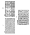
図5は操作部10から選択された画像ファイルの第1・第2画像データ、当該第2画像データに基づいた2D表示、および当該第1・第2画像データに基づいた3D表示の一例を示す。 FIG. 5 shows an example of the first and second image data of the image file selected from the operation unit 10, 2D display based on the second image data, and 3D display based on the first and second image data. .
図5(a)に示すように、操作部10から選択された画像ファイルの第1・第2画像データは、それぞれ右画像、左画像を示しており、これらがVRAM43に読み出されているとする。
As shown in FIG. 5A, the first and second image data of the image file selected from the operation unit 10 indicate a right image and a left image, respectively, and these are read out to the
この場合、図5(b)に示すように、まず基準撮像部から得られた第2画像データを2D画像として表示した上、OKキーの押下があるか、あるいは2D表示がされたまま所定時間が経過した場合は、3D表示を行う。 In this case, as shown in FIG. 5B, first, the second image data obtained from the reference imaging unit is displayed as a 2D image, and the OK key is pressed or the 2D display is kept for a predetermined time. When elapses, 3D display is performed.
以上の処理により、読み出された画像が3D画像であれば、一旦その画像を2D表示し、ユーザが画像の2D表示を終了する指示を入力した場合、2D表示は即座に3D表示に切り換わる。また、2D表示がされたまま所定時間が経過した場合も、2D表示が3D表示に切り換わるが、所定時間が経過する前に2D表示を終了する指示が入力された場合、2D表示は即座に3D表示に切り換わる。このように、一旦画像を2D表示して指示があった場合に3D表示に切り換えることで、観察者の目の疲労の軽減と3D表示への切り換えの高速化を同時に実現できる。 As a result of the above processing, if the read image is a 3D image, the image is temporarily displayed in 2D, and when the user inputs an instruction to end the 2D display of the image, the 2D display is immediately switched to 3D display. . Also, when a predetermined time elapses while 2D display is being performed, the 2D display is switched to 3D display. However, if an instruction to end the 2D display is input before the predetermined time elapses, the 2D display is immediately Switch to 3D display. In this way, once the image is displayed in 2D and an instruction is given, the display is switched to 3D display, thereby simultaneously reducing the observer's eye fatigue and speeding up the switching to 3D display.
<第2実施形態>
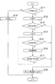
図6は、第2実施形態に係る立体画像表示処理のフローチャートを示す。この処理は、CPU40が実行を制御する。この処理をCPU40に実行させるためのプログラムはROM51に記憶されている。なお、CPU40と同等のハードウェア構成を有するパソコンなどから、以下の処理の1または複数の撮像装置による実行を制御することができるので、CPU40は必ずしもカメラ2に内蔵される必要はない。
Second Embodiment
FIG. 6 shows a flowchart of a stereoscopic image display process according to the second embodiment. This process is controlled by the
S11、S12はS1、S2と同様である。 S11 and S12 are the same as S1 and S2.
S13では、操作部10から2D表示を中断する指示が入力されたか否かを判断する。当該指示が入力された場合はS18、入力されない場合はS14に進む。 In S13, it is determined whether or not an instruction to interrupt 2D display is input from the operation unit 10. If the instruction is input, the process proceeds to S18, and if not, the process proceeds to S14.
S14では、VRAM43の第1・第2画像データの漸進的3D表示を行う。漸進的3D表示とは、第1・第2画像データの視差量すなわち水平方向の表示位置のずれが目標視差量に達するまで、モニター11における第1・第2画像データの視差量をゼロの状態から徐々に広げていきながら3D表示を行うことである。第1・第2画像データの最初の表示位置ずれ量は0であるが、後述のS16でこのずれ量は増加される。
In S14, a progressive 3D display of the first and second image data in the
S15では、漸進的3D表示中断の指示が入力されたか否かの判断を行う。当該指示が入力された場合はS18、入力されない場合はS16に進む。 In S15, it is determined whether or not an instruction for gradual 3D display interruption has been input. If the instruction is input, the process proceeds to S18, and if not, the process proceeds to S16.
S16では、モニター11における第1・第2画像データの位置ずれ量を所定の値(例えば2画素)だけインクリメントし、そのインクリメントされた位置ずれ量だけ左右画像をモニター11上で逆方向にシフトして3D表示する。また、第1・第2画像データの位置ずれ量は、画面中央部で大きく周辺部で小さいなど画面全体で一様でない場合もあるため、ずれ量を場所によって変えることも可能である。
In S16, the positional deviation amount of the first and second image data on the
S17では、S16の結果、視差量が目標視差量に達したか否かを判断する。視差量が目標視差量に達した場合はS18に進み、達していない場合はS15に戻る。 In S17, it is determined whether the parallax amount has reached the target parallax amount as a result of S16. If the amount of parallax has reached the target amount of parallax, the process proceeds to S18, and if not, the process returns to S15.
S18では、目標視差量を有する3D画像を表示する。S12の2D表示からS18の3D表示への切り換えは、右目用画像を第2画像データから第1画像データに置き換えることで行われる。その置き換えの際には、第2画像データの表示領域を徐々に第1画像データの表示領域に置き換えていくフェード効果を用いてもよい。 In S18, a 3D image having the target parallax amount is displayed. Switching from the 2D display in S12 to the 3D display in S18 is performed by replacing the right-eye image from the second image data to the first image data. In the replacement, a fade effect may be used in which the display area of the second image data is gradually replaced with the display area of the first image data.
S19は、S6と同様である。 S19 is the same as S6.
なお、インクリメントさせる位置ずらし量は時間と共に増加させてもよい。図7は時間軸に沿った漸進的3D表示の位置ずれ量の関係の一例を示す。図7の(a)でt1とt2の間は直線で例を示しているが、二次関数や指数関数等の非線形関数としても良い。また、図8は当該時間軸に沿った漸進的3D表示の表示例を示す。 Note that the position shift amount to be incremented may be increased with time. FIG. 7 shows an example of the relationship between the positional deviation amounts of the progressive 3D display along the time axis. In FIG. 7A, a straight line is shown between t1 and t2, but a nonlinear function such as a quadratic function or an exponential function may be used. FIG. 8 shows a display example of progressive 3D display along the time axis.
まず、S12(時刻t0)で2D表示が開始し、S13(時刻t0)およびS15(時刻t3)で中断指示がない場合は、時刻t1〜t3への進行に沿ってずれ量がゼロから所定の値ずつインクリメントされていくことが繰り返される(図7(a))。なお図示の簡略のため、図7(a)ではインクリメント量が微小で線形直線であるが、実際は同一のずらし量の上昇が時間の経過に従って階段状に現れる。 First, when 2D display starts at S12 (time t0) and there is no interruption instruction at S13 (time t0) and S15 (time t3), the amount of deviation increases from zero to a predetermined value along the progress from time t1 to t3. Incrementing by values is repeated (FIG. 7A). For simplification of illustration, in FIG. 7A, the increment amount is minute and is a linear line, but in reality, the same shift amount rises in a stepped manner as time passes.
仮に、2回目以降のS15〜S17のループにおいて、中断指示が入力された場合(S15で”Yes”)、S18に移行し、その中断指示の入力時点である時刻t4で、即座に目標視差量の3D表示が開始する(図7(b))。 If an interruption instruction is input in the second and subsequent loops of S15 to S17 ("Yes" in S15), the process proceeds to S18, and immediately at the time t4 when the interruption instruction is input, the target amount of parallax is instantaneous. 3D display starts (FIG. 7B).
さらに、S13で中断指示が入力された場合(S13で”Yes”)、S15〜S17のループには一度も進むことなく、その中断指示の入力時点である時刻t5で、即座に目標視差量の3D表示が開始する(図7(c))。 Furthermore, when an interruption instruction is input in S13 (“Yes” in S13), the process does not proceed to the loop of S15 to S17, and the target parallax amount is immediately set at time t5 that is the input time of the interruption instruction. 3D display starts (FIG. 7C).
図8(a)は時刻t0のずれ量がゼロの左右画像、図8(b)は時刻t1の左右画像、図8(c)は時刻t3の左右画像、図8(d)は時刻t2、t4、またはt5の左右画像のモニター11への一例を示す。各時刻t1〜t5の漸進的3D表示では、図8の左右画像で図3(a)ないし(b)の左右画像を各時刻t1〜t5の時点で置き換えて3D表示すると考えればよい。つまり、漸進的3D表示では、モニター11の同一画像表示面に図8(a)〜(d)の左右画像の短冊状の画像断片を交互に配列して表示する。
8A is a left and right image with zero deviation at time t0, FIG. 8B is a left and right image at time t1, FIG. 8C is a left and right image at time t3, and FIG. 8D is a time t2. An example of the left and right images on the
以上の処理により、視差量が目標視差量に向けて徐々に変化していく漸進的3D表示を行うことで、観察者の目の疲労を軽減することができる。また、漸進的3D表示の中断が指示されれば即座に目標視差量の3D表示に切り換わる。よって、目の疲労軽減と3D表示への切り換えの高速化を両立できる。 Through the above-described process, it is possible to reduce fatigue of the eyes of the observer by performing progressive 3D display in which the parallax amount gradually changes toward the target parallax amount. In addition, if an instruction to interrupt progressive 3D display is given, the display immediately switches to 3D display of the target parallax amount. Therefore, it is possible to reduce both eye fatigue and increase the speed of switching to 3D display.
<第3実施形態>
図9は、第3実施形態に係る立体画像表示処理のフローチャートを示す。この処理は、CPU40が実行を制御する。この処理をCPU40に実行させるためのプログラムはROM51に記憶されている。なお、CPU40と同等のハードウェア構成を有するパソコンなどから、以下の処理の1または複数の撮像装置による実行を制御することができるので、CPU40は必ずしもカメラ2に内蔵される必要はない。
<Third Embodiment>
FIG. 9 shows a flowchart of a stereoscopic image display process according to the third embodiment. This process is controlled by the
S21〜S25はS1〜S5と同様である。ただし、S25の終了後はS26に進む。 S21 to S25 are the same as S1 to S5. However, after S25 ends, the process proceeds to S26.
S26では、スライドショー終了指示が入力されたか否かの判断を行う。当該指示があった場合は処理を終了し、当該指示がない場合はS27に進む。 In S26, it is determined whether or not a slide show end instruction has been input. If there is such an instruction, the process ends, and if there is no such instruction, the process proceeds to S27.
S27では、S24と同様の判断を行う。所定時間が経過した場合はS31に進み、経過していない場合はS25に戻る。ただし、このS27の所定時間(3D終了指示待機時間)の長さはS24の所定時間(2D終了指示待機時間)の長さと同一でなくてもよい。 In S27, the same determination as in S24 is performed. If the predetermined time has elapsed, the process proceeds to S31, and if not, the process returns to S25. However, the length of the predetermined time (3D end instruction waiting time) in S27 may not be the same as the length of the predetermined time (2D end instruction waiting time) in S24.
S28は、S6と同様である。 S28 is the same as S6.
S29は、S23と同様の判断を行う。指示があった場合は処理を終了し、指示がない場合はS30に進む。 In S29, the same determination as in S23 is performed. If there is an instruction, the process ends. If there is no instruction, the process proceeds to S30.
S30では、S24と同様の判断を行う。所定時間が経過した場合はS31に進み、経過していない場合はS28に戻る。 In S30, the same determination as in S24 is performed. If the predetermined time has elapsed, the process proceeds to S31, and if not, the process returns to S28.
S31では、S21で読み出された画像ファイルをVRAM43から消去し、消去された画像ファイルの次の順序の画像ファイル(ファイル名の昇順/降順、タイムスタンプ順などで劣後するもの)をメモリカード49からVRAM43に読み出す。
In S31, the image file read in S21 is erased from the
S32はS25と同様である。 S32 is the same as S25.
以上の処理によると、画像が3D画像の場合は一旦2D表示を行い、2D表示の終了指示が入力されたかまたは当該指示が入力されないまま所定時間が経過した場合は2D表示を3D表示に切り換える。3D表示の途中でスライドショー終了指示がユーザから行われた場合(例えばOKボタンの押下)、即座にスライドショー表示を中止する。3D表示の途中でスライドショー終了指示がないまま所定時間が経過した場合は、次の画像を読み込んで2D表示を開始し、以後同様に、2D表示終了指示が入力されたか当該指示が入力されないまま所定時間が経過した場合は当該2D表示を3D表示に切り換える(図10参照)。これにより、3D画像を用いたスライドショーではまず2D表示を行い、頻繁に3D表示画像が切り換えられることを防いで観察者の目の疲労を軽減するとともに、所望の画像の2D表示から3D表示への切り換えの高速化を同時に実現できる。 According to the above processing, when the image is a 3D image, 2D display is once performed, and when a 2D display end instruction is input or when a predetermined time has passed without the instruction being input, the 2D display is switched to 3D display. If a slide show end instruction is issued from the user during the 3D display (for example, pressing the OK button), the slide show display is immediately stopped. When a predetermined time elapses without a slide show end instruction in the middle of 3D display, the next image is read to start 2D display, and thereafter, similarly, a 2D display end instruction is input or a predetermined instruction is not input. When the time has elapsed, the 2D display is switched to the 3D display (see FIG. 10). As a result, in a slide show using 3D images, first, 2D display is performed to prevent frequent switching of the 3D display images, thereby reducing the eyestrain of the observer and changing the desired image from 2D display to 3D display. High speed switching can be realized at the same time.
1a:第1撮影光学系、1b:第2撮影光学系、21:第1ズームレンズ、22:第1フォーカスレンズ、23:第1絞り、28:第1イメージセンサ、31:第2ズームレンズ、32:第2フォーカスレンズ、38:第2絞り、33:第2イメージセンサ、40:CPU、45:3D画像生成部、82:視差量算出部 1a: first imaging optical system, 1b: second imaging optical system, 21: first zoom lens, 22: first focus lens, 23: first aperture, 28: first image sensor, 31: second zoom lens, 32: second focus lens, 38: second aperture, 33: second image sensor, 40: CPU, 45: 3D image generation unit, 82: parallax amount calculation unit
Claims (9)
前記所定の記憶媒体に入力された複数の視点画像に基づいて所定の表示装置に立体画像を表示することが可能な表示制御部と、
を備え、
前記表示制御部は、前記画像入力部が複数の視点画像を所定の記憶媒体に入力した場合、平面画像終了の指示が入力されるまで、前記複数の視点画像のうち所望の基準視点画像に基づいて所定の表示装置に平面画像を表示するとともに、前記平面画像終了の指示が入力されたことに応じて所定の表示装置に前記立体画像を表示し、
前記表示制御部は、前記平面画像を表示した際に、前記基準視点画像および前記基準視点画像以外の視点画像である非基準視点画像の視差量を徐々に広げるずらし表示の終了の指示が入力されない場合、前記基準視点画像および前記非基準視点画像の視差量が所定値となるまで前記基準視点画像および前記非基準視点画像の視差量を所定量ずつずらして前記表示装置に立体画像を表示し、前記ずらし表示の終了指示が入力された場合または前記基準視点画像および前記非基準視点画像の視差量が前記所定値となった場合、前記表示装置に前記立体画像を表示する立体画像表示装置。 An image input unit for inputting a plurality of viewpoint images to a predetermined storage medium;
A display control unit capable of displaying a stereoscopic image on a predetermined display device based on a plurality of viewpoint images input to the predetermined storage medium;
With
When the image input unit inputs a plurality of viewpoint images to a predetermined storage medium, the display control unit is based on a desired reference viewpoint image among the plurality of viewpoint images until an instruction to end the planar image is input. And displaying the planar image on the predetermined display device, and displaying the stereoscopic image on the predetermined display device in response to the input of the instruction to end the planar image ,
When the display control unit displays the planar image, an instruction to end the shift display that gradually increases the parallax amount of the non-reference viewpoint image that is a viewpoint image other than the reference viewpoint image and the reference viewpoint image is not input. In this case, the stereoscopic image is displayed on the display device by shifting the parallax amount between the reference viewpoint image and the non-reference viewpoint image by a predetermined amount until the parallax amount between the reference viewpoint image and the non-reference viewpoint image reaches a predetermined value. A stereoscopic image display device that displays the stereoscopic image on the display device when an instruction to end the shifted display is input or when the parallax amounts of the reference viewpoint image and the non-reference viewpoint image become the predetermined value .
前記画像入力部が、複数の視点画像を所定の記憶媒体に入力するステップと、
前記表示制御部が、前記画像入力部が複数の視点画像を所定の記憶媒体に入力した場合、平面画像終了の指示が入力されるまで、複数の視点画像のうち所望の基準視点画像に基づいて所定の表示装置に平面画像を表示するとともに、前記平面画像終了の指示が入力されたことに応じて、前記複数の視点画像に基づいて立体画像を所定の表示装置に表示するステップと、
前記平面画像を表示した際に、前記基準視点画像および前記基準視点画像以外の視点画像である非基準視点画像の視差量を徐々に広げるずらし表示の終了の指示が入力されない場合、前記基準視点画像および前記非基準視点画像の視差量が所定値となるまで前記基準視点画像および前記非基準視点画像の視差量を所定量ずつずらして前記表示装置に立体画像を表示し、前記ずらし表示の終了指示が入力された場合または前記基準視点画像および前記非基準視点画像の視差量が前記所定値となった場合、前記表示装置に前記立体画像を表示するステップと、
を実行する立体画像表示方法。 In a stereoscopic image display device including an image input unit and a display control unit,
The image input unit inputting a plurality of viewpoint images to a predetermined storage medium;
When the image input unit inputs a plurality of viewpoint images to a predetermined storage medium, the display control unit is based on a desired reference viewpoint image among the plurality of viewpoint images until an instruction to end the planar image is input. Displaying a planar image on a predetermined display device, and displaying a stereoscopic image on the predetermined display device based on the plurality of viewpoint images in response to an input of the instruction to end the planar image;
When an instruction to end the shift display for gradually increasing the parallax amount of the non-reference viewpoint image that is a viewpoint image other than the reference viewpoint image and the reference viewpoint image is not input when the planar image is displayed, the reference viewpoint image In addition, the stereoscopic image is displayed on the display device by shifting the parallax amounts of the reference viewpoint image and the non-reference viewpoint image by a predetermined amount until the parallax amount of the non-reference viewpoint image reaches a predetermined value, and an instruction to end the shifted display is displayed. Or when the parallax amount of the reference viewpoint image and the non-reference viewpoint image reaches the predetermined value, displaying the stereoscopic image on the display device;
3D image display method for executing
前記画像入力部が、複数の視点画像を所定の記憶媒体に入力するステップと、
前記表示制御部が、前記画像入力部が複数の視点画像を所定の記憶媒体に入力した場合、平面画像終了の指示が入力されるまで、複数の視点画像のうち所望の基準視点画像に基づいて所定の表示装置に平面画像を表示するとともに、前記平面画像終了の指示が入力されたことに応じて、前記複数の視点画像に基づいて立体画像を所定の表示装置に表示するステップと、
前記平面画像を表示した際に、前記基準視点画像および前記基準視点画像以外の視点画像である非基準視点画像の視差量を徐々に広げるずらし表示の終了の指示が入力されない場合、前記基準視点画像および前記非基準視点画像の視差量が所定値となるまで前記基準視点画像および前記非基準視点画像の視差量を所定量ずつずらして前記表示装置に立体画像を表示し、前記ずらし表示の終了指示が入力された場合または前記基準視点画像および前記非基準視点画像の視差量が前記所定値となった場合、前記表示装置に前記立体画像を表示するステップと、
を実行するためのプログラム。 In a stereoscopic image display device including an image input unit and a display control unit,
The image input unit inputting a plurality of viewpoint images to a predetermined storage medium;
When the image input unit inputs a plurality of viewpoint images to a predetermined storage medium, the display control unit is based on a desired reference viewpoint image among the plurality of viewpoint images until an instruction to end the planar image is input. Displaying a planar image on a predetermined display device, and displaying a stereoscopic image on the predetermined display device based on the plurality of viewpoint images in response to an input of the instruction to end the planar image;
When an instruction to end the shift display for gradually increasing the parallax amount of the non-reference viewpoint image that is a viewpoint image other than the reference viewpoint image and the reference viewpoint image is not input when the planar image is displayed, the reference viewpoint image In addition, the stereoscopic image is displayed on the display device by shifting the parallax amounts of the reference viewpoint image and the non-reference viewpoint image by a predetermined amount until the parallax amount of the non-reference viewpoint image reaches a predetermined value, and an instruction to end the shifted display is displayed. Or when the parallax amount of the reference viewpoint image and the non-reference viewpoint image reaches the predetermined value, displaying the stereoscopic image on the display device;
A program for running.
前記所定の記憶媒体に入力された複数の視点画像に基づいて所定の表示装置に立体画像を表示することが可能な表示制御部と、
を備え、
前記表示制御部は、前記撮像部が複数の視点画像を所定の記憶媒体に入力した場合、平面画像終了の指示が入力されるまで、前記複数の視点画像のうち所望の基準視点画像に基づいて所定の表示装置に平面画像を表示するとともに、前記平面画像終了の指示が入力されたことに応じて所定の表示装置に前記立体画像を表示し、
前記平面画像を表示した際に、前記基準視点画像および前記基準視点画像以外の視点画像である非基準視点画像の視差量を徐々に広げるずらし表示の終了の指示が入力されない場合、前記基準視点画像および前記非基準視点画像の視差量が所定値となるまで前記基準視点画像および前記非基準視点画像の視差量を所定量ずつずらして前記表示装置に立体画像を表示し、前記ずらし表示の終了指示が入力された場合または前記基準視点画像および前記非基準視点画像の視差量が前記所定値となった場合、前記表示装置に前記立体画像を表示する撮像装置。 An imaging unit that inputs a plurality of viewpoint images obtained by photoelectrically converting a subject image formed through each of a plurality of optical systems to a predetermined storage medium; and
A display control unit capable of displaying a stereoscopic image on a predetermined display device based on a plurality of viewpoint images input to the predetermined storage medium;
With
When the imaging unit inputs a plurality of viewpoint images to a predetermined storage medium, the display control unit is based on a desired reference viewpoint image among the plurality of viewpoint images until an instruction to end the planar image is input. A planar image is displayed on a predetermined display device, and the stereoscopic image is displayed on the predetermined display device in response to an input of the instruction to end the planar image .
When an instruction to end the shift display for gradually increasing the parallax amount of the non-reference viewpoint image that is a viewpoint image other than the reference viewpoint image and the reference viewpoint image is not input when the planar image is displayed, the reference viewpoint image In addition, the stereoscopic image is displayed on the display device by shifting the parallax amounts of the reference viewpoint image and the non-reference viewpoint image by a predetermined amount until the parallax amount of the non-reference viewpoint image reaches a predetermined value, and an instruction to end the shifted display is displayed. An image pickup apparatus that displays the stereoscopic image on the display device when a parallax amount between the reference viewpoint image and the non-reference viewpoint image reaches the predetermined value .
前記撮像部が、複数の光学系の各々を介して結像した被写体像を撮像素子により光電変換して得られた複数の視点画像を、所定の記憶媒体に入力するステップと、
前記表示制御部が、前記撮像部が複数の視点画像を所定の記憶媒体に入力した場合、平面画像終了の指示が入力されるまで、複数の視点画像のうち所望の基準視点画像に基づいて所定の表示装置に平面画像を表示するとともに、前記平面画像終了の指示が入力されたことに応じて、前記複数の視点画像に基づいて立体画像を所定の表示装置に表示するステップと、
前記平面画像を表示した際に、前記基準視点画像および前記基準視点画像以外の視点画像である非基準視点画像の視差量を徐々に広げるずらし表示の終了の指示が入力されない場合、前記基準視点画像および前記非基準視点画像の視差量が所定値となるまで前記基準視点画像および前記非基準視点画像の視差量を所定量ずつずらして前記表示装置に立体画像を表示し、前記ずらし表示の終了指示が入力された場合または前記基準視点画像および前記非基準視点画像の視差量が前記所定値となった場合、前記表示装置に前記立体画像を表示するステップと、
を実行する立体画像表示方法。 In an imaging apparatus including an imaging unit and a display control unit,
A step of inputting, into a predetermined storage medium, a plurality of viewpoint images obtained by photoelectrically converting a subject image formed through each of a plurality of optical systems by an imaging element;
When the imaging unit inputs a plurality of viewpoint images to a predetermined storage medium, the display control unit is predetermined based on a desired reference viewpoint image among the plurality of viewpoint images until an instruction to end the planar image is input. Displaying a planar image on the display device, and displaying a stereoscopic image on a predetermined display device based on the plurality of viewpoint images in response to the input of the instruction to end the planar image;
When an instruction to end the shift display for gradually increasing the parallax amount of the non-reference viewpoint image that is a viewpoint image other than the reference viewpoint image and the reference viewpoint image is not input when the planar image is displayed, the reference viewpoint image In addition, the stereoscopic image is displayed on the display device by shifting the parallax amounts of the reference viewpoint image and the non-reference viewpoint image by a predetermined amount until the parallax amount of the non-reference viewpoint image reaches a predetermined value, and an instruction to end the shifted display is displayed. Or when the parallax amount of the reference viewpoint image and the non-reference viewpoint image reaches the predetermined value, displaying the stereoscopic image on the display device;
3D image display method for executing
前記撮像部が、複数の光学系の各々を介して結像した被写体像を撮像素子により光電変換して得られた複数の視点画像を、所定の記憶媒体に入力するステップと、
前記表示制御部が、前記撮像部が複数の視点画像を所定の記憶媒体に入力した場合、平面画像終了の指示が入力されるまで、複数の視点画像のうち所望の基準視点画像に基づいて所定の表示装置に平面画像を表示するとともに、前記平面画像終了の指示が入力されたことに応じて、前記複数の視点画像に基づいて立体画像を所定の表示装置に表示するステップと、
前記平面画像を表示した際に、前記基準視点画像および前記基準視点画像以外の視点画像である非基準視点画像の視差量を徐々に広げるずらし表示の終了の指示が入力されない場合、前記基準視点画像および前記非基準視点画像の視差量が所定値となるまで前記基準視点画像および前記非基準視点画像の視差量を所定量ずつずらして前記表示装置に立体画像を表示し、前記ずらし表示の終了指示が入力された場合または前記基準視点画像および前記非基準視点画像の視差量が前記所定値となった場合、前記表示装置に前記立体画像を表示するステップと、
を実行するためのプログラム。 In an imaging apparatus including an imaging unit and a display control unit,
A step of inputting, into a predetermined storage medium, a plurality of viewpoint images obtained by photoelectrically converting a subject image formed through each of a plurality of optical systems by an imaging element;
When the imaging unit inputs a plurality of viewpoint images to a predetermined storage medium, the display control unit is predetermined based on a desired reference viewpoint image among the plurality of viewpoint images until an instruction to end the planar image is input. Displaying a planar image on the display device, and displaying a stereoscopic image on a predetermined display device based on the plurality of viewpoint images in response to the input of the instruction to end the planar image;
When an instruction to end the shift display for gradually increasing the parallax amount of the non-reference viewpoint image that is a viewpoint image other than the reference viewpoint image and the reference viewpoint image is not input when the planar image is displayed, the reference viewpoint image In addition, the stereoscopic image is displayed on the display device by shifting the parallax amounts of the reference viewpoint image and the non-reference viewpoint image by a predetermined amount until the parallax amount of the non-reference viewpoint image reaches a predetermined value, and an instruction to end the shifted display is displayed. Or when the parallax amount of the reference viewpoint image and the non-reference viewpoint image reaches the predetermined value, displaying the stereoscopic image on the display device;
A program for running.
Priority Applications (4)
| Application Number | Priority Date | Filing Date | Title |
|---|---|---|---|
| JP2009170252A JP5336285B2 (en) | 2009-07-21 | 2009-07-21 | Stereoscopic image display apparatus, method and program, and imaging apparatus |
| US12/835,334 US20110018977A1 (en) | 2009-07-21 | 2010-07-13 | Stereoscopic image display apparatus, method, recording medium and image pickup apparatus |
| EP10251278A EP2280553A3 (en) | 2009-07-21 | 2010-07-16 | Steroscopic image display display apparatus, method, recording medium and image pickup apparatus |
| CN201010235665.2A CN101964917B (en) | 2009-07-21 | 2010-07-21 | Steroscopic image display apparatus, method, recording medium and image pickup apparatus |
Applications Claiming Priority (1)
| Application Number | Priority Date | Filing Date | Title |
|---|---|---|---|
| JP2009170252A JP5336285B2 (en) | 2009-07-21 | 2009-07-21 | Stereoscopic image display apparatus, method and program, and imaging apparatus |
Publications (3)
| Publication Number | Publication Date |
|---|---|
| JP2011029701A JP2011029701A (en) | 2011-02-10 |
| JP2011029701A5 JP2011029701A5 (en) | 2012-02-23 |
| JP5336285B2 true JP5336285B2 (en) | 2013-11-06 |
Family
ID=42937469
Family Applications (1)
| Application Number | Title | Priority Date | Filing Date |
|---|---|---|---|
| JP2009170252A Expired - Fee Related JP5336285B2 (en) | 2009-07-21 | 2009-07-21 | Stereoscopic image display apparatus, method and program, and imaging apparatus |
Country Status (4)
| Country | Link |
|---|---|
| US (1) | US20110018977A1 (en) |
| EP (1) | EP2280553A3 (en) |
| JP (1) | JP5336285B2 (en) |
| CN (1) | CN101964917B (en) |
Families Citing this family (10)
| Publication number | Priority date | Publication date | Assignee | Title |
|---|---|---|---|---|
| JP2012029216A (en) * | 2010-07-27 | 2012-02-09 | Sony Corp | Reproduction device, reproduction method, and program |
| KR101633336B1 (en) * | 2010-10-01 | 2016-06-24 | 엘지전자 주식회사 | Mobile terminal and method for controlling thereof |
| KR101737840B1 (en) * | 2010-11-05 | 2017-05-19 | 엘지전자 주식회사 | Mobile terminal and method for controlling the same |
| EP2487914A1 (en) * | 2011-02-10 | 2012-08-15 | Thomson Licensing | Reproduction device and method for operating a graphics subsystem in the reproduction device |
| JP2012244571A (en) * | 2011-05-24 | 2012-12-10 | Funai Electric Co Ltd | Stereoscopic image display device |
| US9883176B2 (en) | 2011-12-21 | 2018-01-30 | Panasonic Intellectual Property Corporation Of America | Display device |
| TWI514349B (en) * | 2014-06-05 | 2015-12-21 | Au Optronics Corp | Display device and method of switching display mode |
| JP6666657B2 (en) * | 2015-04-30 | 2020-03-18 | 任天堂株式会社 | Display device |
| CN109936736A (en) * | 2017-12-19 | 2019-06-25 | 深圳Tcl新技术有限公司 | A kind of method, storage medium and smart television automatically switching 3D mode |
| JP7484242B2 (en) * | 2020-03-10 | 2024-05-16 | 株式会社リコー | Image processing device, image processing method, imaging device, image processing system, and program |
Family Cites Families (14)
| Publication number | Priority date | Publication date | Assignee | Title |
|---|---|---|---|---|
| JPH11164328A (en) * | 1997-11-27 | 1999-06-18 | Toshiba Corp | Stereoscopic video image display device |
| JP2000050194A (en) * | 1998-07-27 | 2000-02-18 | Sony Corp | Image pickup device |
| JP2000134642A (en) * | 1998-10-21 | 2000-05-12 | Toshiba Corp | Stereoscopic video reproducing device provided with stereoscopic mode and planar mode and method therefor |
| JP3935812B2 (en) * | 2002-10-11 | 2007-06-27 | シャープ株式会社 | Electronic device having 2D (2D) and 3D (3D) display functions |
| JP3935821B2 (en) * | 2002-10-30 | 2007-06-27 | シャープ株式会社 | Electronic device having 2D (2D) and 3D (3D) display functions |
| JP4490074B2 (en) * | 2003-04-17 | 2010-06-23 | ソニー株式会社 | Stereoscopic image processing apparatus, stereoscopic image display apparatus, stereoscopic image providing method, and stereoscopic image processing system |
| JP2004320559A (en) * | 2003-04-17 | 2004-11-11 | Sharp Corp | Solid image display apparatus |
| JP4121888B2 (en) * | 2003-04-28 | 2008-07-23 | シャープ株式会社 | Content display device and content display program |
| JP2005223495A (en) * | 2004-02-04 | 2005-08-18 | Sharp Corp | Stereoscopic video image display apparatus and method |
| JP5011842B2 (en) * | 2006-06-22 | 2012-08-29 | 株式会社ニコン | Image playback device |
| JP4982286B2 (en) * | 2007-07-25 | 2012-07-25 | 株式会社リコー | Imaging device |
| JP2009049751A (en) * | 2007-08-21 | 2009-03-05 | Toshiba Corp | Stereoscopic image display apparatus |
| BRPI0820739B1 (en) * | 2007-12-14 | 2020-10-20 | Koninklijke Philips N.V. | method of reproducing video information, reproduction device for reproducing video information, signal, and, recording carrier |
| JP4512649B2 (en) * | 2008-03-31 | 2010-07-28 | シャープ株式会社 | Image forming apparatus |
-
2009
- 2009-07-21 JP JP2009170252A patent/JP5336285B2/en not_active Expired - Fee Related
-
2010
- 2010-07-13 US US12/835,334 patent/US20110018977A1/en not_active Abandoned
- 2010-07-16 EP EP10251278A patent/EP2280553A3/en not_active Withdrawn
- 2010-07-21 CN CN201010235665.2A patent/CN101964917B/en not_active Expired - Fee Related
Also Published As
| Publication number | Publication date |
|---|---|
| EP2280553A2 (en) | 2011-02-02 |
| CN101964917A (en) | 2011-02-02 |
| US20110018977A1 (en) | 2011-01-27 |
| JP2011029701A (en) | 2011-02-10 |
| EP2280553A3 (en) | 2012-06-13 |
| CN101964917B (en) | 2015-04-15 |
Similar Documents
| Publication | Publication Date | Title |
|---|---|---|
| JP5336285B2 (en) | Stereoscopic image display apparatus, method and program, and imaging apparatus | |
| JP5450200B2 (en) | Imaging apparatus, method and program | |
| US8135270B2 (en) | Imaging device and imaging method | |
| JP5390707B2 (en) | Stereoscopic panorama image synthesis apparatus, imaging apparatus, stereo panorama image synthesis method, recording medium, and computer program | |
| KR101391042B1 (en) | Image processing device capable of generating wide-range image | |
| JP5788518B2 (en) | Monocular stereoscopic photographing apparatus, photographing method and program | |
| KR101346426B1 (en) | Image processing device capable of generating wide-range image | |
| JP5371845B2 (en) | Imaging apparatus, display control method thereof, and three-dimensional information acquisition apparatus | |
| JP5647740B2 (en) | Parallax adjusting apparatus and method, photographing apparatus, reproduction display apparatus | |
| US8760567B2 (en) | Photographing apparatus and method to reduce auto-focus time | |
| JP4533735B2 (en) | Stereo imaging device | |
| EP2715428B1 (en) | Imaging device | |
| JP2013123210A (en) | Image-capturing apparatus | |
| JP2011013425A (en) | Image pickup apparatus, zoom correction information creating method and program | |
| JP5409483B2 (en) | Imaging device | |
| WO2013047641A1 (en) | Three-dimensional image processing device and three-dimensional image processing method | |
| CN112534330B (en) | Image pickup apparatus | |
| KR101805006B1 (en) | Photographing apparatus and photographing method | |
| JP6071295B2 (en) | Focus adjustment device, imaging device, and control method of focus adjustment device | |
| JP2010161492A (en) | Image pickup device and method for displaying image | |
| JP5648563B2 (en) | Image processing apparatus, image processing method, and program | |
| JP5641352B2 (en) | Image processing apparatus, image processing method, and program | |
| JP2016080738A (en) | Imaging apparatus and automatic focusing method | |
| JP2012209896A (en) | Image processor, imaging apparatus and program | |
| JP2013017096A (en) | Imaging apparatus, image generation device, method and program for controlling them, and recording medium |
Legal Events
| Date | Code | Title | Description |
|---|---|---|---|
| A521 | Request for written amendment filed |
Free format text: JAPANESE INTERMEDIATE CODE: A523 Effective date: 20120105 |
|
| A621 | Written request for application examination |
Free format text: JAPANESE INTERMEDIATE CODE: A621 Effective date: 20120105 |
|
| A977 | Report on retrieval |
Free format text: JAPANESE INTERMEDIATE CODE: A971007 Effective date: 20121203 |
|
| A131 | Notification of reasons for refusal |
Free format text: JAPANESE INTERMEDIATE CODE: A131 Effective date: 20121205 |
|
| A521 | Request for written amendment filed |
Free format text: JAPANESE INTERMEDIATE CODE: A523 Effective date: 20130204 |
|
| TRDD | Decision of grant or rejection written | ||
| A01 | Written decision to grant a patent or to grant a registration (utility model) |
Free format text: JAPANESE INTERMEDIATE CODE: A01 Effective date: 20130725 |
|
| A61 | First payment of annual fees (during grant procedure) |
Free format text: JAPANESE INTERMEDIATE CODE: A61 Effective date: 20130801 |
|
| R150 | Certificate of patent or registration of utility model |
Ref document number: 5336285 Country of ref document: JP Free format text: JAPANESE INTERMEDIATE CODE: R150 Free format text: JAPANESE INTERMEDIATE CODE: R150 |
|
| R250 | Receipt of annual fees |
Free format text: JAPANESE INTERMEDIATE CODE: R250 |
|
| R250 | Receipt of annual fees |
Free format text: JAPANESE INTERMEDIATE CODE: R250 |
|
| R250 | Receipt of annual fees |
Free format text: JAPANESE INTERMEDIATE CODE: R250 |
|
| R250 | Receipt of annual fees |
Free format text: JAPANESE INTERMEDIATE CODE: R250 |
|
| R250 | Receipt of annual fees |
Free format text: JAPANESE INTERMEDIATE CODE: R250 |
|
| R250 | Receipt of annual fees |
Free format text: JAPANESE INTERMEDIATE CODE: R250 |
|
| LAPS | Cancellation because of no payment of annual fees |