JP5335028B2 - Plastic bottle manufacturing method - Google Patents
Plastic bottle manufacturing method Download PDFInfo
- Publication number
- JP5335028B2 JP5335028B2 JP2011116864A JP2011116864A JP5335028B2 JP 5335028 B2 JP5335028 B2 JP 5335028B2 JP 2011116864 A JP2011116864 A JP 2011116864A JP 2011116864 A JP2011116864 A JP 2011116864A JP 5335028 B2 JP5335028 B2 JP 5335028B2
- Authority
- JP
- Japan
- Prior art keywords
- preform
- blow molding
- inspection
- thickness
- molding process
- Prior art date
- Legal status (The legal status is an assumption and is not a legal conclusion. Google has not performed a legal analysis and makes no representation as to the accuracy of the status listed.)
- Active
Links
- 238000004519 manufacturing process Methods 0.000 title claims description 14
- 238000007689 inspection Methods 0.000 claims description 64
- 238000000071 blow moulding Methods 0.000 claims description 58
- 229920005989 resin Polymers 0.000 claims description 13
- 239000011347 resin Substances 0.000 claims description 13
- 238000000034 method Methods 0.000 claims description 6
- 229920000139 polyethylene terephthalate Polymers 0.000 description 27
- 239000005020 polyethylene terephthalate Substances 0.000 description 27
- 238000005520 cutting process Methods 0.000 description 13
- 238000010586 diagram Methods 0.000 description 9
- 239000004677 Nylon Substances 0.000 description 7
- 229920001778 nylon Polymers 0.000 description 7
- 238000000465 moulding Methods 0.000 description 4
- 238000005259 measurement Methods 0.000 description 2
- 235000013361 beverage Nutrition 0.000 description 1
- 210000000078 claw Anatomy 0.000 description 1
- 230000003247 decreasing effect Effects 0.000 description 1
- 239000007788 liquid Substances 0.000 description 1
- 239000000463 material Substances 0.000 description 1
- -1 polyethylene terephthalate Polymers 0.000 description 1
- 238000003825 pressing Methods 0.000 description 1
- 229920003002 synthetic resin Polymers 0.000 description 1
- 239000000057 synthetic resin Substances 0.000 description 1
Images


Classifications
-
- B—PERFORMING OPERATIONS; TRANSPORTING
- B29—WORKING OF PLASTICS; WORKING OF SUBSTANCES IN A PLASTIC STATE IN GENERAL
- B29C—SHAPING OR JOINING OF PLASTICS; SHAPING OF MATERIAL IN A PLASTIC STATE, NOT OTHERWISE PROVIDED FOR; AFTER-TREATMENT OF THE SHAPED PRODUCTS, e.g. REPAIRING
- B29C49/00—Blow-moulding, i.e. blowing a preform or parison to a desired shape within a mould; Apparatus therefor
- B29C49/42—Component parts, details or accessories; Auxiliary operations
- B29C49/78—Measuring, controlling or regulating
- B29C49/783—Measuring, controlling or regulating blowing pressure
-
- B—PERFORMING OPERATIONS; TRANSPORTING
- B29—WORKING OF PLASTICS; WORKING OF SUBSTANCES IN A PLASTIC STATE IN GENERAL
- B29C—SHAPING OR JOINING OF PLASTICS; SHAPING OF MATERIAL IN A PLASTIC STATE, NOT OTHERWISE PROVIDED FOR; AFTER-TREATMENT OF THE SHAPED PRODUCTS, e.g. REPAIRING
- B29C49/00—Blow-moulding, i.e. blowing a preform or parison to a desired shape within a mould; Apparatus therefor
- B29C49/42—Component parts, details or accessories; Auxiliary operations
- B29C49/78—Measuring, controlling or regulating
- B29C49/786—Temperature
- B29C2049/7867—Temperature of the heating or cooling means
- B29C2049/78675—Temperature of the heating or cooling means of the heating means
-
- B—PERFORMING OPERATIONS; TRANSPORTING
- B29—WORKING OF PLASTICS; WORKING OF SUBSTANCES IN A PLASTIC STATE IN GENERAL
- B29C—SHAPING OR JOINING OF PLASTICS; SHAPING OF MATERIAL IN A PLASTIC STATE, NOT OTHERWISE PROVIDED FOR; AFTER-TREATMENT OF THE SHAPED PRODUCTS, e.g. REPAIRING
- B29C49/00—Blow-moulding, i.e. blowing a preform or parison to a desired shape within a mould; Apparatus therefor
- B29C49/42—Component parts, details or accessories; Auxiliary operations
- B29C49/78—Measuring, controlling or regulating
- B29C2049/787—Thickness
-
- B—PERFORMING OPERATIONS; TRANSPORTING
- B29—WORKING OF PLASTICS; WORKING OF SUBSTANCES IN A PLASTIC STATE IN GENERAL
- B29C—SHAPING OR JOINING OF PLASTICS; SHAPING OF MATERIAL IN A PLASTIC STATE, NOT OTHERWISE PROVIDED FOR; AFTER-TREATMENT OF THE SHAPED PRODUCTS, e.g. REPAIRING
- B29C2795/00—Printing on articles made from plastics or substances in a plastic state
- B29C2795/002—Printing on articles made from plastics or substances in a plastic state before shaping
-
- B—PERFORMING OPERATIONS; TRANSPORTING
- B29—WORKING OF PLASTICS; WORKING OF SUBSTANCES IN A PLASTIC STATE IN GENERAL
- B29C—SHAPING OR JOINING OF PLASTICS; SHAPING OF MATERIAL IN A PLASTIC STATE, NOT OTHERWISE PROVIDED FOR; AFTER-TREATMENT OF THE SHAPED PRODUCTS, e.g. REPAIRING
- B29C2949/00—Indexing scheme relating to blow-moulding
- B29C2949/07—Preforms or parisons characterised by their configuration
- B29C2949/0715—Preforms or parisons characterised by their configuration the preform having one end closed
-
- B—PERFORMING OPERATIONS; TRANSPORTING
- B29—WORKING OF PLASTICS; WORKING OF SUBSTANCES IN A PLASTIC STATE IN GENERAL
- B29C—SHAPING OR JOINING OF PLASTICS; SHAPING OF MATERIAL IN A PLASTIC STATE, NOT OTHERWISE PROVIDED FOR; AFTER-TREATMENT OF THE SHAPED PRODUCTS, e.g. REPAIRING
- B29C49/00—Blow-moulding, i.e. blowing a preform or parison to a desired shape within a mould; Apparatus therefor
- B29C49/02—Combined blow-moulding and manufacture of the preform or the parison
- B29C49/06—Injection blow-moulding
Landscapes
- Engineering & Computer Science (AREA)
- Manufacturing & Machinery (AREA)
- Mechanical Engineering (AREA)
- Blow-Moulding Or Thermoforming Of Plastics Or The Like (AREA)
Description
本発明は、原型となるプリフォームからブロー成形工程によって形成される樹脂製ボトルの製造方法に関する。 The present invention relates to a method for producing a resin bottle formed from a preform as a prototype by a blow molding process.
飲料等の液状内容物を収容する容器には様々な材質のものがある。その一種として、合成樹脂製ボトル、例えばポリエチレンテレフタレート製のブロー成形ボトル(PETボトル)が知られている。特許文献1には、ブロー成形工程によって、原型となるプリフォームからPETボトルを形成する方法が開示されている。具体的には、一端に開口を有し、他端が閉塞した有底円筒状のプリフォームを加熱し、このプリフォームにおける開口側の首部を把持した状態でプリフォームの胴部をPETボトルの外形と同じ形状に形成された金型の内部に挿入する。そして、プリフォームの開口から高圧空気を導入することによって、プリフォームを金型の内部に密着するように膨張させてPETボトルを形成する。このPETボトルは、品質検査において、検査部位毎に輪切り状に切断されて複数のカット片に分割される。
There are various materials for containers for storing liquid contents such as beverages. As one type, a synthetic resin bottle, for example, a blow molded bottle (PET bottle) made of polyethylene terephthalate is known.
図7は、PETボトルを検査部位毎に切断したときの状態図である。図7の例では、PETボトル10を4つのカット片10a〜10dに分割している。品質検査では、各カット片10a〜10dの重量、肉厚、座屈強度などを計測し、計測結果を予め設定された設定値と比較することによって品質を検査する。計測結果と、設定値との差異が大きい場合には、品質検査の結果をブロー成形工程にフィードバックし、プリフォームの温度などのブロー成形の条件を調整する。これによって、PETボトルの良品率を向上させている。例えば、肉厚が設定値よりも薄くなっていた部位は、プリフォームにおいても他の部位と比較して肉厚が薄かった部位であると考えられる。これは、プリフォームにおける肉厚の薄い部位には熱が伝わりやすいので、ブロー成形工程において、他の部位に対して相対的に温度が高くなり、高圧空気の導入によって他の部位よりも大きく膨張したと考えられるからである。したがって、この部位の温度を低く設定することによって、肉厚を設定値に近づけることができる。
FIG. 7 is a state diagram when the PET bottle is cut for each inspection region. In the example of FIG. 7, the
しかしながら、このような品質検査では、ブロー成形工程の後でなければプリフォームの温度などのブロー成形の条件を調整することができないので、ブロー成形の条件が適切に調整されていない状態で一旦はPETボトルを成形することになる。したがって、ブロー成形の条件を最適化するのにPETボトルの成形を繰り返す必要があるので、PETボトルの製造効率が低下するという問題がある。 However, in such a quality inspection, the blow molding conditions such as the temperature of the preform can be adjusted only after the blow molding process. Therefore, once the blow molding conditions are not properly adjusted, A PET bottle will be molded. Therefore, since it is necessary to repeat the molding of the PET bottle in order to optimize the blow molding conditions, there is a problem that the production efficiency of the PET bottle is lowered.
本発明の目的は、樹脂製ボトルの成形を繰り返すことなくブロー成形の条件を最適化することによって、樹脂製ボトルの製造効率を向上させることである。 An object of the present invention is to improve the production efficiency of a resin bottle by optimizing the blow molding conditions without repeating the molding of the resin bottle.
かかる課題を解決すべく、本発明は、第1のステップと、第2のステップと、第3のステップとを有し、原型となるプリフォームからブロー成形工程によって形成される樹脂製ボトルの製造方法を提供する。第1のステップでは、プリフォームの胴部に設定された複数の検査部位のそれぞれの重量または肉厚を計測する。第2のステップでは、第1のステップにて計測された重量または肉厚のそれぞれを予め設定された設定値と比較することによって、第1のステップにて計測された重量または肉厚と、設定値との差異を検査部位毎に検査する。第3のステップでは、検査部位毎の検査結果に応じて、ブロー成形工程におけるブロー成形の条件を調整する。 In order to solve this problem, the present invention has a first step, a second step, and a third step, and manufactures a resin bottle formed from a preform as a prototype by a blow molding process. Provide a method. In the first step, the weight or thickness of each of the plurality of inspection sites set on the body of the preform is measured. In the second step, the weight or thickness measured in the first step is set by comparing each of the weight or thickness measured in the first step with a preset set value. The difference from the value is inspected for each inspection part. In the third step, the blow molding conditions in the blow molding process are adjusted according to the inspection result for each inspection site.
ここで、本発明において、第3のステップでは、検査部位毎の温度を調整することによって、ブロー成形工程におけるブロー成形の条件を調整することが好ましい。また、第3のステップでは、プリフォームに導入する空気の圧力を調整することによって、ブロー成形工程におけるブロー成形の条件を調整することが好ましい。また、第3のステップでは、プリフォームに空気を導入するタイミングを調整することによって、ブロー成形工程におけるブロー成形の条件を調整することが好ましい。さらに、第1のステップでは、プリフォームの胴部を検査部位毎に切断した後、検査部位毎に重量または肉厚を計測することが好ましい。 Here, in the present invention, in the third step, it is preferable to adjust the conditions for blow molding in the blow molding process by adjusting the temperature for each inspection site. In the third step, it is preferable to adjust the conditions of blow molding in the blow molding process by adjusting the pressure of air introduced into the preform. In the third step, it is preferable to adjust the blow molding conditions in the blow molding process by adjusting the timing of introducing air into the preform. Furthermore, in the first step, it is preferable to measure the weight or thickness for each inspection site after cutting the body of the preform for each inspection site.
本発明によれば、プリフォームの胴部に設定された複数の検査部位のそれぞれの重量または肉厚を計測し、計測された重量または肉厚のそれぞれを予め設定された設定値と比較することによって、計測された重量または肉厚と、設定値との差異を検査部位毎に検査する。そして、検査部位毎の検査結果に応じて、ブロー成形工程におけるブロー成形の条件を調整する。したがって、樹脂製ボトルの成形を繰り返すことなく、すなわちブロー成形工程を経ることなくブロー成形の条件を最適化することができるので、樹脂製ボトルの製造効率を向上させることができる。 According to the present invention, the weight or thickness of each of a plurality of inspection sites set on the body of the preform is measured, and each of the measured weight or thickness is compared with a preset set value. Thus, the difference between the measured weight or thickness and the set value is inspected for each inspection region. Then, the blow molding conditions in the blow molding process are adjusted according to the inspection result for each inspection site. Therefore, the conditions for blow molding can be optimized without repeating the molding of the resin bottle, that is, without going through the blow molding process, so that the production efficiency of the resin bottle can be improved.
図1は、本実施形態に係るプリフォームおよびその切断装置の模式図である。PETボトル(樹脂製ボトル)の原型となるプリフォーム1は、一端に開口を有し、他端を閉塞した有底円筒状に形成されている。このプリフォーム1は、PETボトルの蓋を取り付けるためのネジ部が形成された開口側の首部11と、その他の部分である胴部12とを有している。
FIG. 1 is a schematic view of a preform and a cutting device thereof according to the present embodiment. A
切断装置2は、プリフォーム1を切断する装置である。この切断装置2は、旋盤における切削工具をカッターに代えたものであり、基礎21と、主軸台22と、スライダ23とを主体に構成されている。主軸台22は、回転軸(主軸)周りに回転可能なチャック22Aと、チャック22Aを回転させるモータ(図示略)とを有する。チャック22Aの中心軸は、回転軸と一致している。スライダ23は、ハンドル23Aを回転させることによって、基礎21上を図1の紙面左右方向に沿って進退可能に構成されている(図1(a),(b)参照)。このスライダ23は、刃物台24を備える。刃物台24は、ハンドル24Aを回転させることによって、スライダ23上を図1の紙面垂直方向に沿って進退可能に構成されている。また、刃物台24には、刃の向きが主軸台22の回転軸と直交するようにカッター25が固定されている。
The cutting device 2 is a device that cuts the
図2は、チャック22Aの拡大斜視図である。チャック22Aは、三つ爪のチャックである。このチャック22Aは、円筒状のナイロンチャック3を介してプリフォーム1の首部11を把持する。チャック22Aにて首部11を直に把持すると、首部11の外周に形成された凹凸状のネジ部を三つ爪で把持することになるので、首部11を安定して固定することができない。したがって、プリフォーム1の中心軸と、チャック22Aの中心軸とを一致させにくい。これに対して、ナイロンチャック3を介して首部11を把持すると、ナイロンチャック3の表面には凹凸がないので、首部11を安定して把持することができる。したがって、プリフォーム1の中心軸と、チャック22Aの中心軸、すなわち主軸台22の回転軸とを容易に一致させることができる(図1参照)。また、ナイロンチャック3には、中心軸の方向に沿ってスリット3Aが形成されている。これによれば、ナイロンチャック3の径を拡縮させることができるので、首部11に対してナイロンチャック3を着脱しやすい。
FIG. 2 is an enlarged perspective view of the
次に、プリフォーム1を検査する方法について説明する。プリフォーム1の胴部12には、予め複数の検査部位が設定されている。そして、切断装置2を用いてプリフォーム1を切断することによって、胴部12を各検査部位に分割する。具体的には、まず、プリフォーム1の中心軸と、主軸台22の回転軸とを一致させるように、チャック22Aにプリフォーム1の首部11を把持させる。次に、ハンドル23Aを回転させることによって、スライダ23を進退させて所定の位置、すなわち各検査部位の切断位置までカッター25の刃を移動させる。次に、主軸台22のモータを駆動してプリフォーム1を回転軸周りに回転させる。そして、ハンドル24Aを回転させることによって、刃物台24を移動させてカッター25の刃をプリフォーム1の胴部12に押し込む。これにより、プリフォーム1を回転軸と直交する方向に沿って検査部位ごとに輪切り状に切断する。この切断に際しては、首部11から離れた検査部位から順番にプリフォーム1を切断していく。
Next, a method for inspecting the
図3は、プリフォーム1を検査部位毎に切断したときの状態図である。図3の例では、プリフォーム1の首部11を除いた胴部12は、3つの検査部位12a〜12cに分割されている。プリフォーム1の品質検査では、胴部12を検査部位毎に切断した後、各検査部位12a〜12cのそれぞれの肉厚を計測する(第1のステップ)。そして、各検査部位12a〜12cの肉厚のそれぞれを予め設定された設定値と比較することによって、各検査部位12a〜12cの肉厚と、設定値との差異を検査部位毎に検査する(第2のステップ)。なお、各検査部位12a〜12cの肉厚は、各検査部位12a〜12cの重量を計測することによって推定してもよい。
FIG. 3 is a state diagram when the
図4は、ブロー成形機の全体模式図である。PETボトル4は、プリフォーム1をブロー成形機5に投入し、ブロー成形工程を実行することで形成される。以下、PETボトル4の製造方法について説明する。
FIG. 4 is an overall schematic diagram of the blow molding machine. The
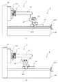
図5は、ブロー成形の工程説明図である。このブロー成形工程は、5つの工程を有している。第1の工程では、ブロー成形機5内に設けられたブロー成形用ヒータ51にてプリフォーム1を加熱して温度を調整する。ブロー成形用ヒータ51は、プリフォーム1の外周に沿った形状のヒータをプリフォーム1の中心軸に沿って複数配設した構成とされている。換言すれば、ブロー成形用ヒータ51は、プリフォーム1の検査部位のそれぞれに対応して設けられている。第2の工程では、PETボトル4の外形と同じ形状に形成された金型52の内部にプリフォーム1の胴部12を挿入する。第3の工程では、首部11の開口から延伸棒53を挿入してプリフォーム1を中心軸に沿って押圧することによって押し延ばす。第4の工程では、首部11の開口から高圧空気を導入することで金型52の内部に密着するようにプリフォーム1を膨張させてPETボトル4を成形する。第5の工程では、PETボトル4を冷却した後、金型52を開いて取り出す。
FIG. 5 is an explanatory view of a blow molding process. This blow molding process has five processes. In the first step, the
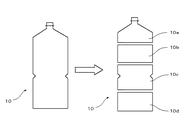
図6は、プリフォームおよびPETボトルの対応関係図である。第2の工程において、ブロー成形用ヒータ51の温度(ブロー成形の条件)は、プリフォーム1の検査部位毎の検査結果に応じて調整される(第3のステップ)。ここで、ブロー成形工程において、他の部位よりも相対的に温度の低い部位は膨張しにくく、他の部位よりも相対的に温度の高い部位は膨張しやすい。したがって、肉厚が設定値よりも薄い検査部位の温度は他の検査部位よりも相対的に低く調整される。また、肉厚が設定値よりも厚い検査部位の温度は他の検査部位よりも相対的に高く調整される。例えば、検査部位12aの肉厚が設定値よりも薄い場合、この検査部位に関するブロー成形用ヒータ51の温度を他の検査部位12b,12cよりも相対的に低くする。これにより、検査部位12aは、ブロー成形工程において、他の検査部位12b,12cよりも膨張しにくくなる。したがって、PETボトル4における検査部位12aの肉厚を設定値に近づけることができる。
FIG. 6 is a correspondence diagram between the preform and the PET bottle. In the second step, the temperature of the blow molding heater 51 (blow molding conditions) is adjusted according to the inspection result for each inspection region of the preform 1 (third step). Here, in the blow molding process, a portion having a relatively lower temperature than other portions is less likely to expand, and a portion having a relatively higher temperature than other portions is likely to expand. Therefore, the temperature of the examination site whose wall thickness is thinner than the set value is adjusted to be relatively lower than other examination sites. In addition, the temperature of the examination site whose thickness is thicker than the set value is adjusted to be relatively higher than that of other examination sites. For example, when the thickness of the
このように、本実施形態によれば、プリフォーム1の胴部12に設定された複数の検査部位12a〜12cのそれぞれの肉厚を計測し、計測された肉厚のそれぞれを予め設定された設定値と比較することによって、計測された肉厚と、設定値との差異を検査部位毎に検査する。そして、検査部位毎の検査結果に応じて、ブロー成形用ヒータ51の温度を調整する。したがって、PETボトル4の成形を繰り返すことなくブロー成形用ヒータ51の温度を最適化することができるので、PETボトル4の製造効率を向上させることができる。
Thus, according to the present embodiment, the thickness of each of the plurality of
なお、上述した実施形態では、プリフォーム1を切断装置2にて切断した後、各検査部位12a〜12cの肉厚を計測していた。これに対して、例えば、プリフォームの形状を計測する装置などを用いることによって、プリフォームを切断することなく各検査部位の肉厚を計測してもよい。また、各検査部位の肉厚に代えて重量を計測してもよい。要するに、第1のステップでは、プリフォームの胴部に設定された複数の検査部位のそれぞれの重量または肉厚を計測すればよい。
In the above-described embodiment, after the
また、上述した実施形態では、プリフォーム1の検査部位毎の検査結果に応じて、ブロー成形用ヒータ51の温度を調整していた。これに対して、検査結果に応じて調整するブロー成形の条件は、他の条件であってもよい。例えば、プリフォームに導入する高圧空気の圧力を調整してもよい。この場合、圧力を低くすることによって、肉厚を厚くすることができる。これに対して、圧力を高くすることによって、肉厚を薄くすることができる。また、例えば、プリフォームに高圧空気を導入するタイミングを調整してもよい。この場合、タイミングを遅くすることによって、高圧空気を導入する際のプリフォームの温度は低くなるので、肉厚を厚くすることができる。これに対して、タイミングを早くすることによって、高圧空気を導入する際のプリフォームの温度は高くなるので、肉厚を薄くすることができる。
In the above-described embodiment, the temperature of the
さらに、上述した実施形態において、プリフォーム1の検査部位毎の検査は、ブロー成形をする全部のプリフォーム1に対して行う必要はなく、ブロー成形機5に投入するプリフォームの一部について検査するだけであってもよい。例えば、同一の製造ロットのプリフォーム1の内1個又は数個を抽出して検査すればよい。この場合、1個又は数個のプリフォーム1の検査結果に応じて調整したブロー成形の条件で、ブロー成形をする全てのプリフォーム1についてブロー成形を行い、PETボトルを製造することができる。
Further, in the above-described embodiment, the inspection for each inspection region of the
以上のように、本発明は、原型となるプリフォームからブロー成形工程によって形成される樹脂製ボトルの製造方法に広く適用できる。 As described above, the present invention can be widely applied to a method of manufacturing a resin bottle formed from a preform as a prototype by a blow molding process.
1 プリフォーム
2 切断装置
3 ナイロンチャック
3A スリット
4 PETボトル(樹脂製ボトル)
5 ブロー成形機
11 首部
12 胴部
12a−12c 検査部位
21 基礎
22 主軸台
22A チャック
23 スライダ
23A ハンドル
24 刃物台
24A ハンドル
25 カッター
51 ブロー成形用ヒータ
52 金型
53 延伸棒
DESCRIPTION OF
5
Claims (5)
前記プリフォームの胴部に設定された複数の検査部位のそれぞれの重量または肉厚を計測する第1のステップと、
前記第1のステップにて計測された重量または肉厚のそれぞれを予め設定された設定値と比較することによって、前記第1のステップにて計測された重量または肉厚と、前記設定値との差異を前記検査部位毎に検査する第2のステップと、
前記検査部位毎の検査結果に応じて、前記ブロー成形工程におけるブロー成形の条件を調整する第3のステップと
を有することを特徴とする樹脂製ボトルの製造方法。 In a method for producing a resin bottle formed by a blow molding process from a preform as a prototype,
A first step of measuring the weight or thickness of each of a plurality of inspection sites set on the body of the preform;
By comparing each of the weight or thickness measured in the first step with a preset set value, the weight or thickness measured in the first step and the set value A second step of inspecting the difference for each inspection site;
And a third step of adjusting a blow molding condition in the blow molding process according to an inspection result for each inspection site.
Priority Applications (9)
| Application Number | Priority Date | Filing Date | Title |
|---|---|---|---|
| JP2011116864A JP5335028B2 (en) | 2011-05-25 | 2011-05-25 | Plastic bottle manufacturing method |
| SG2013086004A SG195074A1 (en) | 2011-05-25 | 2012-05-22 | Method for producing resin bottles |
| PCT/JP2012/062989 WO2012161171A1 (en) | 2011-05-25 | 2012-05-22 | Method for producing resin bottles |
| NZ616760A NZ616760B2 (en) | 2011-05-25 | 2012-05-22 | Method for producing resin bottles |
| US14/112,560 US9555576B2 (en) | 2011-05-25 | 2012-05-22 | Method for producing resin bottles |
| ES12789773.4T ES2608154T3 (en) | 2011-05-25 | 2012-05-22 | Method to produce resin bottles |
| EP12789773.4A EP2716431B1 (en) | 2011-05-25 | 2012-05-22 | Method for producing resin bottles |
| TW101118182A TWI503220B (en) | 2011-05-25 | 2012-05-22 | Method for manufacturing resin bottles |
| CN2012101638129A CN102794903A (en) | 2011-05-25 | 2012-05-23 | Method for producing resin bottles |
Applications Claiming Priority (1)
| Application Number | Priority Date | Filing Date | Title |
|---|---|---|---|
| JP2011116864A JP5335028B2 (en) | 2011-05-25 | 2011-05-25 | Plastic bottle manufacturing method |
Publications (2)
| Publication Number | Publication Date |
|---|---|
| JP2012245636A JP2012245636A (en) | 2012-12-13 |
| JP5335028B2 true JP5335028B2 (en) | 2013-11-06 |
Family
ID=47194320
Family Applications (1)
| Application Number | Title | Priority Date | Filing Date |
|---|---|---|---|
| JP2011116864A Active JP5335028B2 (en) | 2011-05-25 | 2011-05-25 | Plastic bottle manufacturing method |
Country Status (8)
| Country | Link |
|---|---|
| US (1) | US9555576B2 (en) |
| EP (1) | EP2716431B1 (en) |
| JP (1) | JP5335028B2 (en) |
| CN (1) | CN102794903A (en) |
| ES (1) | ES2608154T3 (en) |
| SG (1) | SG195074A1 (en) |
| TW (1) | TWI503220B (en) |
| WO (1) | WO2012161171A1 (en) |
Cited By (2)
| Publication number | Priority date | Publication date | Assignee | Title |
|---|---|---|---|---|
| WO2023126406A1 (en) * | 2021-12-30 | 2023-07-06 | Sidel Participations | Method for producing containers, and facility for implementing the method |
| EP4275866A1 (en) * | 2022-05-09 | 2023-11-15 | Krones AG | Method and device for producing plastic containers with zone-by-zone inspection of plastic preforms |
Families Citing this family (3)
| Publication number | Priority date | Publication date | Assignee | Title |
|---|---|---|---|---|
| CN106626325B (en) * | 2016-11-30 | 2019-05-03 | 蔡怀峰 | The processing method of angle packing tube |
| KR102002149B1 (en) * | 2017-04-26 | 2019-07-24 | 에이테크솔루션(주) | Method of manufacturing optical mirror for head-up display |
| DE102021128918A1 (en) * | 2021-11-05 | 2023-05-11 | Krones Aktiengesellschaft | Device and method for manufacturing plastic containers with inspection |
Family Cites Families (20)
| Publication number | Priority date | Publication date | Assignee | Title |
|---|---|---|---|---|
| US3950459A (en) * | 1972-12-27 | 1976-04-13 | Phillips Petroleum Company | Continuous process for producing, reheating, and blow molding parisons |
| JPS6230020A (en) | 1985-08-01 | 1987-02-09 | Ishikawajima Harima Heavy Ind Co Ltd | Plastic blow molding process |
| DE3816273C3 (en) | 1988-05-12 | 1996-03-21 | Harald Feuerherm | Process for extrusion blow molding of a hollow body and device for carrying out the process |
| JPH0464411A (en) | 1990-07-04 | 1992-02-28 | Ishikawajima Harima Heavy Ind Co Ltd | Controlling method for parison-shape |
| JPH0813498B2 (en) * | 1992-02-29 | 1996-02-14 | 日精エー・エス・ビー機械株式会社 | Molding method for heat-resistant container |
| JP3233980B2 (en) * | 1992-04-27 | 2001-12-04 | 本田技研工業株式会社 | Blow molding molding control system and molding control method |
| DE19544634A1 (en) | 1995-11-30 | 1997-06-05 | Feuerherm Harald | Process for blow molding hollow bodies made of thermoplastic |
| JP3799788B2 (en) | 1997-12-25 | 2006-07-19 | 凸版印刷株式会社 | Molding method of plastic bottle |
| DE19813668C2 (en) | 1998-03-27 | 2003-04-30 | Ossberger Gmbh & Co | Manufacturing device with control devices for a hollow plastic body |
| EP1719970A3 (en) | 2000-03-01 | 2009-11-18 | Plastic Technologies, Inc. | Method and apparatus for measuring wall thickness of a plastic container |
| PT1279002E (en) | 2000-03-01 | 2006-05-31 | Plastic Techn Inc | MEDICATION OF THE WALL THICKNESS MEDIUM OF A PLASTIC CONTAINER |
| JP3597508B2 (en) * | 2001-02-06 | 2004-12-08 | 花王株式会社 | Preform design method and apparatus |
| WO2002062558A1 (en) * | 2001-02-06 | 2002-08-15 | Kao Corporation | Method and device for design of preform |
| JP2003062896A (en) * | 2001-08-24 | 2003-03-05 | Lion Corp | System for designing container wall thickness and container wall thickness designing method |
| US20060058911A1 (en) * | 2004-09-13 | 2006-03-16 | Graham Packaging Company, L.P. | System and method for phase monitoring during blow molding |
| CN101249721B (en) | 2008-03-13 | 2010-09-08 | 华南理工大学 | Extrusion blow moulding wall-thickness on-line control system based on image recognition technology and method thereof |
| DE102008052611B3 (en) | 2008-10-21 | 2010-04-08 | Feuerherm, Harald, Dipl.-Ing. | Plastic hollow body producing method, involves detecting variations of wall thickness distribution of hollow bodies, and correcting variations by intervening molding process or by changing outflow speed of plastic melt from die gap |
| DE102008057999A1 (en) * | 2008-11-13 | 2010-05-20 | Khs Corpoplast Gmbh & Co. Kg | Method and apparatus for blow molding containers |
| DE102009035868A1 (en) * | 2009-07-31 | 2011-02-03 | Krones Ag | Device for forming plastic preforms with synchronous heating and stretching |
| JP5738070B2 (en) | 2011-05-25 | 2015-06-17 | サントリーホールディングス株式会社 | Preform cutting device |
-
2011
- 2011-05-25 JP JP2011116864A patent/JP5335028B2/en active Active
-
2012
- 2012-05-22 US US14/112,560 patent/US9555576B2/en active Active
- 2012-05-22 EP EP12789773.4A patent/EP2716431B1/en active Active
- 2012-05-22 WO PCT/JP2012/062989 patent/WO2012161171A1/en active Application Filing
- 2012-05-22 ES ES12789773.4T patent/ES2608154T3/en active Active
- 2012-05-22 TW TW101118182A patent/TWI503220B/en not_active IP Right Cessation
- 2012-05-22 SG SG2013086004A patent/SG195074A1/en unknown
- 2012-05-23 CN CN2012101638129A patent/CN102794903A/en active Pending
Cited By (3)
| Publication number | Priority date | Publication date | Assignee | Title |
|---|---|---|---|---|
| WO2023126406A1 (en) * | 2021-12-30 | 2023-07-06 | Sidel Participations | Method for producing containers, and facility for implementing the method |
| FR3131557A1 (en) * | 2021-12-30 | 2023-07-07 | Sidel Participations | Process for manufacturing containers and installation for its implementation |
| EP4275866A1 (en) * | 2022-05-09 | 2023-11-15 | Krones AG | Method and device for producing plastic containers with zone-by-zone inspection of plastic preforms |
Also Published As
| Publication number | Publication date |
|---|---|
| WO2012161171A1 (en) | 2012-11-29 |
| EP2716431B1 (en) | 2016-12-07 |
| EP2716431A4 (en) | 2015-09-23 |
| NZ616760A (en) | 2014-09-26 |
| ES2608154T3 (en) | 2017-04-06 |
| CN102794903A (en) | 2012-11-28 |
| TWI503220B (en) | 2015-10-11 |
| SG195074A1 (en) | 2013-12-30 |
| JP2012245636A (en) | 2012-12-13 |
| US9555576B2 (en) | 2017-01-31 |
| US20140077404A1 (en) | 2014-03-20 |
| EP2716431A1 (en) | 2014-04-09 |
| TW201313446A (en) | 2013-04-01 |
Similar Documents
| Publication | Publication Date | Title |
|---|---|---|
| JP5335028B2 (en) | Plastic bottle manufacturing method | |
| RU2577270C2 (en) | Drawing rod appliance for fluid forming with blowing | |
| JP6736124B2 (en) | Method for manufacturing pressure-resistant container, preform and container used in the manufacturing method | |
| RU2627858C2 (en) | Method and device for optimized bottom contour manufacture on workpiece | |
| EP2463079A1 (en) | A process for single-step forming and filling of containers | |
| JP6130792B2 (en) | Reverse stretch rods for machine hygiene and processing | |
| JP6359829B2 (en) | Design of HYDROBLOW preform (preform) | |
| EP3362254B1 (en) | Method of inspecting a blow molded container made from a preform having an etched tip, and container. | |
| EP3059069B1 (en) | A method for manufacturing bent-neck bottles, and a machine for implementing said method | |
| CN113453869B (en) | Method for manufacturing eccentric container and mold for temperature adjustment | |
| JP2023085377A (en) | Stretch blow molded pipette, and system and method for forming the same | |
| US10173360B2 (en) | Hollow container manufacturing method and manufacturing apparatus | |
| JP5738070B2 (en) | Preform cutting device | |
| EP1684965A1 (en) | Integral handle pet container system | |
| JP4748475B2 (en) | Injection molding preform | |
| JP2019523721A (en) | Stretch blow molded plastic container with integrally formed gripping region and method for manufacturing plastic container | |
| EP2633977B1 (en) | Production method for hollow container | |
| US20220274311A1 (en) | Die unit, blow molding device, and blow molding method | |
| NZ616760B2 (en) | Method for producing resin bottles | |
| WO2023157863A1 (en) | Temperature adjustment mold, temperature adjustment method, and resin container manufacturing device | |
| JP2018501130A (en) | Container having a wide-mouthed neck fitted with a threaded sleeve | |
| JP2024507838A (en) | Thin pipette with enhanced mechanical performance | |
| Berezanskii et al. | Experience in planning and manufacture of equipment for the production of extrusion blow moulded products | |
| KR20160072362A (en) | Neck Jig For Blow Molding Machine | |
| CN106514991A (en) | Method for manufacturing tool tank |
Legal Events
| Date | Code | Title | Description |
|---|---|---|---|
| A621 | Written request for application examination |
Free format text: JAPANESE INTERMEDIATE CODE: A621 Effective date: 20130704 |
|
| A871 | Explanation of circumstances concerning accelerated examination |
Free format text: JAPANESE INTERMEDIATE CODE: A871 Effective date: 20130704 |
|
| TRDD | Decision of grant or rejection written | ||
| A975 | Report on accelerated examination |
Free format text: JAPANESE INTERMEDIATE CODE: A971005 Effective date: 20130719 |
|
| A01 | Written decision to grant a patent or to grant a registration (utility model) |
Free format text: JAPANESE INTERMEDIATE CODE: A01 Effective date: 20130723 |
|
| A61 | First payment of annual fees (during grant procedure) |
Free format text: JAPANESE INTERMEDIATE CODE: A61 Effective date: 20130730 |
|
| R150 | Certificate of patent or registration of utility model |
Ref document number: 5335028 Country of ref document: JP Free format text: JAPANESE INTERMEDIATE CODE: R150 Free format text: JAPANESE INTERMEDIATE CODE: R150 |
|
| R250 | Receipt of annual fees |
Free format text: JAPANESE INTERMEDIATE CODE: R250 |
|
| R250 | Receipt of annual fees |
Free format text: JAPANESE INTERMEDIATE CODE: R250 |
|
| R250 | Receipt of annual fees |
Free format text: JAPANESE INTERMEDIATE CODE: R250 |
|
| R250 | Receipt of annual fees |
Free format text: JAPANESE INTERMEDIATE CODE: R250 |
|
| R250 | Receipt of annual fees |
Free format text: JAPANESE INTERMEDIATE CODE: R250 |
|
| R250 | Receipt of annual fees |
Free format text: JAPANESE INTERMEDIATE CODE: R250 |
|
| R250 | Receipt of annual fees |
Free format text: JAPANESE INTERMEDIATE CODE: R250 |
|
| R250 | Receipt of annual fees |
Free format text: JAPANESE INTERMEDIATE CODE: R250 |
|
| R250 | Receipt of annual fees |
Free format text: JAPANESE INTERMEDIATE CODE: R250 |