JP5331208B2 - Abnormality detection device for permanent magnet type synchronous motor - Google Patents
Abnormality detection device for permanent magnet type synchronous motor Download PDFInfo
- Publication number
- JP5331208B2 JP5331208B2 JP2011528860A JP2011528860A JP5331208B2 JP 5331208 B2 JP5331208 B2 JP 5331208B2 JP 2011528860 A JP2011528860 A JP 2011528860A JP 2011528860 A JP2011528860 A JP 2011528860A JP 5331208 B2 JP5331208 B2 JP 5331208B2
- Authority
- JP
- Japan
- Prior art keywords
- permanent magnet
- type synchronous
- magnet type
- axis voltage
- command value
- Prior art date
- Legal status (The legal status is an assumption and is not a legal conclusion. Google has not performed a legal analysis and makes no representation as to the accuracy of the status listed.)
- Active
Links
Images
Classifications
-
- H—ELECTRICITY
- H02—GENERATION; CONVERSION OR DISTRIBUTION OF ELECTRIC POWER
- H02P—CONTROL OR REGULATION OF ELECTRIC MOTORS, ELECTRIC GENERATORS OR DYNAMO-ELECTRIC CONVERTERS; CONTROLLING TRANSFORMERS, REACTORS OR CHOKE COILS
- H02P5/00—Arrangements specially adapted for regulating or controlling the speed or torque of two or more electric motors
- H02P5/46—Arrangements specially adapted for regulating or controlling the speed or torque of two or more electric motors for speed regulation of two or more dynamo-electric motors in relation to one another
- H02P5/50—Arrangements specially adapted for regulating or controlling the speed or torque of two or more electric motors for speed regulation of two or more dynamo-electric motors in relation to one another by comparing electrical values representing the speeds
-
- B—PERFORMING OPERATIONS; TRANSPORTING
- B60—VEHICLES IN GENERAL
- B60L—PROPULSION OF ELECTRICALLY-PROPELLED VEHICLES; SUPPLYING ELECTRIC POWER FOR AUXILIARY EQUIPMENT OF ELECTRICALLY-PROPELLED VEHICLES; ELECTRODYNAMIC BRAKE SYSTEMS FOR VEHICLES IN GENERAL; MAGNETIC SUSPENSION OR LEVITATION FOR VEHICLES; MONITORING OPERATING VARIABLES OF ELECTRICALLY-PROPELLED VEHICLES; ELECTRIC SAFETY DEVICES FOR ELECTRICALLY-PROPELLED VEHICLES
- B60L3/00—Electric devices on electrically-propelled vehicles for safety purposes; Monitoring operating variables, e.g. speed, deceleration or energy consumption
- B60L3/0023—Detecting, eliminating, remedying or compensating for drive train abnormalities, e.g. failures within the drive train
- B60L3/0061—Detecting, eliminating, remedying or compensating for drive train abnormalities, e.g. failures within the drive train relating to electrical machines
-
- H—ELECTRICITY
- H02—GENERATION; CONVERSION OR DISTRIBUTION OF ELECTRIC POWER
- H02P—CONTROL OR REGULATION OF ELECTRIC MOTORS, ELECTRIC GENERATORS OR DYNAMO-ELECTRIC CONVERTERS; CONTROLLING TRANSFORMERS, REACTORS OR CHOKE COILS
- H02P21/00—Arrangements or methods for the control of electric machines by vector control, e.g. by control of field orientation
- H02P21/14—Estimation or adaptation of machine parameters, e.g. flux, current or voltage
-
- H—ELECTRICITY
- H02—GENERATION; CONVERSION OR DISTRIBUTION OF ELECTRIC POWER
- H02P—CONTROL OR REGULATION OF ELECTRIC MOTORS, ELECTRIC GENERATORS OR DYNAMO-ELECTRIC CONVERTERS; CONTROLLING TRANSFORMERS, REACTORS OR CHOKE COILS
- H02P29/00—Arrangements for regulating or controlling electric motors, appropriate for both AC and DC motors
- H02P29/60—Controlling or determining the temperature of the motor or of the drive
- H02P29/66—Controlling or determining the temperature of the rotor
- H02P29/662—Controlling or determining the temperature of the rotor the rotor having permanent magnets
-
- H—ELECTRICITY
- H02—GENERATION; CONVERSION OR DISTRIBUTION OF ELECTRIC POWER
- H02P—CONTROL OR REGULATION OF ELECTRIC MOTORS, ELECTRIC GENERATORS OR DYNAMO-ELECTRIC CONVERTERS; CONTROLLING TRANSFORMERS, REACTORS OR CHOKE COILS
- H02P6/00—Arrangements for controlling synchronous motors or other dynamo-electric motors using electronic commutation dependent on the rotor position; Electronic commutators therefor
- H02P6/04—Arrangements for controlling or regulating the speed or torque of more than one motor
-
- B—PERFORMING OPERATIONS; TRANSPORTING
- B60—VEHICLES IN GENERAL
- B60L—PROPULSION OF ELECTRICALLY-PROPELLED VEHICLES; SUPPLYING ELECTRIC POWER FOR AUXILIARY EQUIPMENT OF ELECTRICALLY-PROPELLED VEHICLES; ELECTRODYNAMIC BRAKE SYSTEMS FOR VEHICLES IN GENERAL; MAGNETIC SUSPENSION OR LEVITATION FOR VEHICLES; MONITORING OPERATING VARIABLES OF ELECTRICALLY-PROPELLED VEHICLES; ELECTRIC SAFETY DEVICES FOR ELECTRICALLY-PROPELLED VEHICLES
- B60L2220/00—Electrical machine types; Structures or applications thereof
- B60L2220/10—Electrical machine types
- B60L2220/14—Synchronous machines
-
- Y—GENERAL TAGGING OF NEW TECHNOLOGICAL DEVELOPMENTS; GENERAL TAGGING OF CROSS-SECTIONAL TECHNOLOGIES SPANNING OVER SEVERAL SECTIONS OF THE IPC; TECHNICAL SUBJECTS COVERED BY FORMER USPC CROSS-REFERENCE ART COLLECTIONS [XRACs] AND DIGESTS
- Y02—TECHNOLOGIES OR APPLICATIONS FOR MITIGATION OR ADAPTATION AGAINST CLIMATE CHANGE
- Y02T—CLIMATE CHANGE MITIGATION TECHNOLOGIES RELATED TO TRANSPORTATION
- Y02T10/00—Road transport of goods or passengers
- Y02T10/60—Other road transportation technologies with climate change mitigation effect
- Y02T10/64—Electric machine technologies in electromobility
Abstract
Description
本発明は、電動車両用の電動機として用いられる永久磁石型同期電動機の磁石温度の異常を検出する異常検出装置に関する。 The present invention relates to an abnormality detection device for detecting an abnormality in a magnet temperature of a permanent magnet type synchronous motor used as an electric motor for an electric vehicle.
電気自動車やハイブリッド自動車などの電動車両用の電動機としては、トルク密度が高く、小型・高出力化が比較的容易な永久磁石型同期電動機が多く用いられている。電動車両用の電動機として用いられる永久磁石型同期電動機は、出力を維持したまま小型化することで発熱密度が増大し、温度上昇しやすい傾向となる。永久磁石型同期電動機は、永久磁石の温度が所定温度以上になると不可逆減磁を起こして出力が大幅に低下してしまうので、これを避けるために永久磁石の温度を監視することが求められる。しかしながら、永久磁石は回転子側に設置されており、温度センサで直接測温することが困難である。そのため、他の情報から永久磁石の温度を推定する方法が検討されている。 As an electric motor for an electric vehicle such as an electric vehicle or a hybrid vehicle, a permanent magnet type synchronous motor that has a high torque density and is relatively easy to reduce in size and output is often used. Permanent magnet type synchronous motors used as electric motors for electric vehicles tend to increase in heat generation density and tend to rise in temperature by being downsized while maintaining output. Since the permanent magnet type synchronous motor causes irreversible demagnetization when the temperature of the permanent magnet exceeds a predetermined temperature and the output is greatly reduced, it is required to monitor the temperature of the permanent magnet in order to avoid this. However, the permanent magnet is installed on the rotor side, and it is difficult to directly measure the temperature with a temperature sensor. Therefore, a method for estimating the temperature of the permanent magnet from other information has been studied.
その一つとして、例えば特許文献1には、巻線温度と磁石温度との関係をマップ化しておき、巻線温度センサの検出値を見て磁石温度を推定するという技術が記載されている。
As one of them, for example,
特許文献1に記載された技術により永久磁石型同期電動機の磁石温度を高精度に推定するには、固定子側に設けられた巻線の温度と、回転子側に設けられた永久磁石の温度が常に一対一で対応していることが条件となる。ここで、巻線の温度が上昇する主な要因としては、巻線電流に起因する銅損が挙げられる。一方、永久磁石の温度が上昇する主な要因としては、回転子内の磁束密度の大きさと周波数に起因する回転子鉄損が挙げられる。これら銅損と回転子鉄損との関係は、一定の回転子回転速度で且つ一定のトルク指令値のもとでは一対一の関係がある程度確保されるが、回転子の回転速度やトルク指令値が常に変化する電動車両用の電動機としての用途では、銅損と回転子鉄損との関係が刻々と変化することになる。このため、電動車両用の電動機として用いる永久磁石型同期電動機においては、特許文献1に記載された技術により磁石温度を推定することは難しく、磁石温度の異常を精度良く検出することが困難であるとの問題があった。
In order to accurately estimate the magnet temperature of the permanent magnet type synchronous motor by the technique described in
本発明は、以上の従来技術の問題点に鑑みて創案されたものであって、電動車両用の電動機として用いられる永久磁石型同期電動機の磁石温度の異常を高精度に検出することができる異常検出装置を提供することを目的としている。 The present invention was devised in view of the above problems of the prior art, and is capable of detecting an abnormality in the magnet temperature of a permanent magnet type synchronous motor used as an electric motor for an electric vehicle with high accuracy. The object is to provide a detection device.
本発明の第1態様による永久磁石型同期電動機の異常検出装置は、複数の永久磁石型同期電動機と、前記複数の永久磁石型同期電動機に対する電流指令値を算出する電流指令値算出部と、前記電流指令値算出部により各々算出された前記電流指令値に基づいて、前記複数の永久磁石型同期電動機に対するq軸電圧指令値を各々算出するq軸電圧指令値算出部と、前記q軸電圧指令値算出部により算出された前記複数の永久磁石型同期電動機に対する前記q軸電圧指令値のうち、1つの永久磁石型同期電動機に対するq軸電圧指令値と他のいずれか1つの永久磁石型同期電動機に対するq軸電圧指令値との差分を用いて、前記永久磁石型同期電動機の少なくともいずれかに磁石温度の異常が生じているか否かを判定する磁石温度異常判定部と、を備えることを特徴とする。 An abnormality detection device for a permanent magnet type synchronous motor according to a first aspect of the present invention includes a plurality of permanent magnet type synchronous motors, a current command value calculation unit that calculates current command values for the plurality of permanent magnet type synchronous motors, A q-axis voltage command value calculation unit for calculating q-axis voltage command values for the plurality of permanent magnet synchronous motors based on the current command values respectively calculated by the current command value calculation unit, and the q-axis voltage command Of the q-axis voltage command values for the plurality of permanent magnet type synchronous motors calculated by the value calculation unit, the q-axis voltage command value for one permanent magnet type synchronous motor and any one other permanent magnet type synchronous motor A magnet temperature abnormality determination unit that determines whether or not a magnet temperature abnormality has occurred in at least one of the permanent magnet type synchronous motors using a difference from the q-axis voltage command value for Characterized in that it comprises.
本発明の第2態様による永久磁石型同期電動機の異常検出方法は、複数の永久磁石型同期電動機に対する電流指令値を算出する作動と、電流指令値算出作動により各々算出された前記電流指令値に基づいて、前記複数の永久磁石型同期電動機に対するq軸電圧指令値を各々算出する作動と、前記q軸電圧指令値算出作動により算出された前記複数の永久磁石型同期電動機に対する前記q軸電圧指令値のうち、1つの永久磁石型同期電動機に対するq軸電圧指令値と他のいずれか1つの永久磁石型同期電動機に対するq軸電圧指令値との差分を用いて、前記永久磁石型同期電動機の少なくともいずれかに磁石温度の異常が生じているか否かを判定する作動と、を備えることを特徴とする。 The abnormality detection method for a permanent magnet type synchronous motor according to the second aspect of the present invention includes an operation for calculating a current command value for a plurality of permanent magnet type synchronous motors, and a current command value calculated by each of the current command value calculation operations. Based on the operations for calculating q-axis voltage command values for the plurality of permanent magnet type synchronous motors, respectively, and the q-axis voltage commands for the plurality of permanent magnet type synchronous motors calculated by the q-axis voltage command value calculation operation Among the values, the difference between the q-axis voltage command value for one permanent magnet type synchronous motor and the q-axis voltage command value for any one other permanent magnet type synchronous motor is used to determine at least the permanent magnet type synchronous motor. And an operation for determining whether an abnormality of the magnet temperature has occurred in any of the above.
本発明によれば、永久磁石型同期電動機に対するq軸電圧指令値の差分を用いてこれら永久磁石型同期電動機の少なくともいずれかに磁石温度の異常が生じているか否かを判定するようにしている。従って、各永久磁石型同期電動機の永久磁石の温度を温度センサなどで直接計測することなく、電動車両用の電動機として用いられる永久磁石型同期電動機における磁石温度の異常を精度良く検出することができる。 According to the present invention, it is determined whether or not a magnet temperature abnormality has occurred in at least one of the permanent magnet type synchronous motors using the difference in the q-axis voltage command value for the permanent magnet type synchronous motor. . Therefore, it is possible to accurately detect abnormality of the magnet temperature in the permanent magnet type synchronous motor used as the electric motor for the electric vehicle without directly measuring the temperature of the permanent magnet of each permanent magnet type synchronous motor with a temperature sensor or the like. .
以下、本発明の具体的な実施形態について、図面を参照しながら詳細に説明する。 Hereinafter, specific embodiments of the present invention will be described in detail with reference to the drawings.
(第1実施形態)
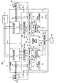
図1は、本発明を適用した電動車両の駆動制御システム100を示す構成図である。この駆動制御システム100は、電動車両の左右二輪を独立して駆動するための2つの永久磁石型同期電動機1,2と、これら2つの永久磁石型同期電動機1,2を駆動制御するインバータ装置3と、電力供給源となるバッテリ4とを備える。(First embodiment)
FIG. 1 is a configuration diagram showing a
2つの永久磁石型同期電動機1,2のうち、電動車両の左側駆動輪を回転させる第1電動機1には、バッテリ4からの直流電力がインバータ装置3の第1電力変換部11にて交流電力に変換されて供給される。第1電力変換部11は、IGBTなどのスイッチング素子のオン/オフがPWM制御されることにより、バッテリ4からの直流電力を所望の交流電力に変換して第1電動機1に供給する。第1電動機1は、この第1電力変換部11からの交流電力により所望のトルクを発生して電動車両の左側駆動輪を回転させる。第1電動機1の回転子回転速度Wlは、速度センサ12によって検出される。また、第1電動機1の巻線温度Tclは、巻線に設置された温度センサ13によって検出される。これら速度センサ12の検出値(回転子回転速度Wl)や温度センサ13の検出値(巻線温度Tcl)は、それぞれインバータ装置3が内蔵するマイコン5に入力される。
Of the two permanent magnet type
一方、電動車両の右側駆動輪を回転させる第2電動機2には、バッテリ4からの直流電力がインバータ装置3の第2電力変換部21にて交流電力に変換されて供給される。第2電力変換部21は、IGBTなどのスイッチング素子のオン/オフがPWM制御されることにより、バッテリ4からの直流電力を所望の交流電力に変換して第2電動機2に供給する。第2電動機2は、この第2電力変換部21からの交流電力により所望のトルクを発生して電動車両の右側駆動輪を回転させる。第2電動機2の回転子回転速度Wrは、速度センサ22によって検出される。また、第2電動機2の巻線温度Tcrは、巻線に設置された温度センサ23によって検出される。これら速度センサ22の検出値(回転子回転速度Wr)や温度センサ23の検出値(巻線温度Tcr)は、それぞれインバータ装置3が内蔵するマイコン5に入力される。
On the other hand, DC power from the
また、第1電力変換部11から第1電動機1への供給電流は電流センサ14により検出され、第2電力変換部21から第2電動機2への供給電流は電流センサ24により検出される。これら電流センサ14,24の検出値もマイコン5に入力される。さらに、マイコン5には、バッテリ4の直流電圧Vdcも入力される。
Further, the current supplied from the
マイコン5は、インバータ装置3の第1電力変換部11及び第2電力変換部21をPWM制御するための制御部であり、電流指令変換部6と、第1電動機1に対応する第1ベクトル制御部15及び第1PWM制御部16と、第2電動機2に対応する第2ベクトル制御部25及び第2PWM制御部26とを備える。
The microcomputer 5 is a control unit for PWM-controlling the first
電流指令変換部6は、車両制御部50からのトルク指令τ*をd軸電流指令値Idl*,Idr*とq軸電流指令値Iql*,Iqr*に変換する。この電流指令変換部6で生成された電流指令値Idl*,Iql*は第1ベクトル制御部15に入力され、電流指令値Idr*,Iqr*は第2ベクトル制御部25に入力される。
Current command conversion unit 6 converts torque command τ * from
第1ベクトル制御部15は、電流センサ14の検出値を3相→2相変換部17にて3相→2相変換し、2相に変換した電流検出値と電流指令変換部6からの電流指令値Idl*,Iql*とに基づいて、電流制御部18にてd軸電圧指令値Vdl*とq軸電圧指令値Vql*を演算する。そして、これら電圧指令値Vdl*,Vql*を2相→3相変換部19にて2相→3相変換して、第1PWM制御部16に出力する。
The first
第1PWM制御部16は、第1ベクトル制御部15からの3相電圧指令値と、バッテリ4の直流電圧Vdcとに基づいて、第1電力変換部11のスイッチング素子を駆動するPWM波形を生成し、第1電力変換部11に供給する。これにより、第1電力変換部11がPWM制御され、第1電動機1がトルク指令値τ*に応じたトルクを発生する。
The first
第2ベクトル制御部25は、第1ベクトル制御部15と同様に、電流センサ24の検出値を3相→2相変換部27にて3相→2相変換し、2相に変換した電流検出値と電流指令変換部6からの電流指令値Idr*,Iqr*とに基づいて、電流制御部28にてd軸電圧指令値Vdr*とq軸電圧指令値Vqr*を演算する。そして、これら電圧指令値Vdr*,Vqr*を2相→3相変換部29にて2相→3相変換して、第2PWM制御部26に出力する。
Similar to the first
第2PWM制御部26は、第1PWM制御部16と同様に、第2ベクトル制御部25からの3相電圧指令値と、バッテリ4の直流電圧Vdcとに基づいて、第2電力変換部21のスイッチング素子を駆動するPWM波形を生成し、第2電力変換部21に供給する。これにより、第2電力変換部21がPWM制御され、第2電動機2がトルク指令値τ*に応じたトルクを発生する。
Similarly to the first
本第1実施形態の電動車両の駆動制御システム100では、以上のインバータ装置3が内蔵するマイコン5に、第1電動機1に対するq軸電圧指令値Vql*と第2電動機2に対するq軸電圧指令値Vqr*とを用いて、第1電動機1と第2電動機2の少なくとも一方に生じた磁石温度の異常を検出する磁石温度異常検出部30の機能が設けられている。つまり、本第1実施形態では、このマイコン5の一機能として本発明の異常検出装置が実現されている。以下、このマイコン5の磁石温度異常検出部30による異常検出処理について、さらに詳しく説明する。
In the
第1電動機1のq軸電圧Vqlは、下記式(1)のように表される。
The q-axis voltage Vql of the first
Vql=ωel・Ldl・Idl+Rl・Iql+p・Lql・Iql+ωel・Φml ・・・(1)
ただし、ωelは第1電動機1の回転子回転速度(電気角)、Ldlは第1電動機1のd軸インダクタンス、Idlは第1電動機1のd軸電流、Rlは第1電動機1の巻線抵抗、Lqlは第1電動機1のq軸インダクタンス、Iqlは第1電動機1のq軸電流、Φmlは第1電動機1の鎖交磁束、pは微分演算子(p=d/dt)である。Vql = ωel·Ldl · Idl + Rl · Iql + p · Lql · Iql + ωel · Φml (1)
Where ωel is the rotor rotational speed (electrical angle) of the
また、同様に、第2電動機2のq軸電圧Vqrは、上記式(1)のサフィックス「l」を「r」に変えた下記式(2)で表される。 Similarly, the q-axis voltage Vqr of the second electric motor 2 is expressed by the following equation (2) in which the suffix “l” in the above equation (1) is changed to “r”.
Vqr=ωer・Ldr・Idr+Rr・Iqr+p・Lqr・Iqr+ωer・Φmr ・・・(2)
ただし、ωerは第2電動機2の回転子回転速度(電気角)、Ldrは第2電動機2のd軸インダクタンス、Idrは第2電動機2のd軸電流、Rrは第2電動機2の巻線抵抗、Lqrは第2電動機2のq軸インダクタンス、Iqrは第2電動機2のq軸電流、Φmrは第2電動機2の鎖交磁束、pは微分演算子(p=d/dt)である。Vqr = ωer · Ldr · Idr + Rr · Iqr + p · Lqr · Iqr + ωer · Φmr (2)
Where ωer is the rotor rotational speed (electrical angle) of the second motor 2, Ldr is the d-axis inductance of the second motor 2, Idr is the d-axis current of the second motor 2, and Rr is the winding resistance of the second motor 2. , Lqr is the q-axis inductance of the second motor 2, Iqr is the q-axis current of the second motor 2, Φmr is the flux linkage of the second motor 2, and p is the differential operator (p = d / dt).
ここで、両電動機1,2において、対応する回転子回転速度ωe(即ち、ωelとωer)、対応する巻線電流Id,Iq(即ち、IdlとIdr、IqlとIqr)、対応する巻線インダクタンスLd,Lq(即ち、LdlとLdr、LqlとLqr)がそれぞれ同じ値という条件の下で、両電動機1,2のq軸電圧VqlとVqrの差Vql−Vqrをとると、上記の式(1)と式(2)とから、下記式(3)が得られる。
Here, in both
Vql−Vqr=(Rl−Rr)Iql+ωel(Φml−Φmr) ・・・(3)
この式(3)のうち、巻線抵抗Rl,Rrは両電動機1,2の巻線温度にそれぞれ依存して変化するが、第1モータ1の巻線温度Tclは温度センサ13により検出され、第2モータ2の巻線温度Tcrは温度センサ23により検出されているので、これら温度センサ13,23の検出値(巻線温度Tcl,Tcr)から巻線抵抗Rr,Rlを推定することが可能である。また、第1モータ1への供給電流は電流センサ14により検出され、回転子回転速度Wlは速度センサ12により検出されているので、これら電流センサ14の検出値(第1モータ1への供給電流)と速度センサ12の検出値(回転子回転速度Wl)とから、q軸電流Iqlと回転子回転速度(電気角)ωelについても検知可能である。したがって、第1電動機1のq軸電圧Vqlと第2電動機2のq軸電圧Vqrとの差分Vql−Vqrから、上記式(3)の右辺第2項のΦml−Φmr、つまり両電動機1,2の鎖交磁束の差を求めることができる。なお、第1電動機1のq軸電圧Vqlと第2電動機2のq軸電圧Vqrとの差分Vql−Vqrは、第1ベクトル制御部15の電流制御部18にて算出されるq軸電圧指令値Vql*と、第2ベクトル制御部25の電流制御部28にて算出されるq軸電圧指令値Vqr*との差分Vql*−Vqr*をとればよい。Vql-Vqr = (Rl-Rr) Iql + .omega.el (.PHI.ml-.PHI.mr) (3)
In this equation (3), the winding resistances Rl and Rr vary depending on the winding temperatures of the two
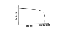
各電動機1,2の鎖交磁束Φml,Φmrは、各々の電動機1,2が備える永久磁石の磁石磁束に比例する。また、各電動機1,2の磁石磁束は、図2に示すように、磁石温度が高温になるほど低下する傾向を有する。温度上昇に対する磁石磁束の低下は非線形であり、磁石温度が高温になるほど低下代が大きくなる。
The interlinkage magnetic fluxes Φml and Φmr of the
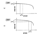
図3は、第1電動機1の磁石温度と第2電動機2の磁石温度にある一定の温度差ΔTがある場合の両電動機1,2の磁石磁束の差を、両電動機1,2の永久磁石が比較的低温の場合と比較的高温の場合とで対比して示した図である。なお、図3(a)は両電動機1,2の永久磁石が比較的低温の場合の磁石磁束の差ΔψLを示し、図3(b)は両電動機1,2の永久磁石が比較的高温の場合の磁石磁束の差ΔψHを示している。
FIG. 3 shows the difference between the magnetic fluxes of the two
図3から分かるように、磁石温度が高温になるほど磁石磁束の低下代が大きくなるため、両電動機1,2の温度差ΔTが等しい場合であっても磁石磁束の差は|ΔψL|<|ΔψH|となる。ここで、各電動機1,2の磁石磁束と鎖交磁束は比例関係にあるので、上記式(3)の鎖交磁束の差Φml−Φmrも、各電動機1,2の磁石温度が高温になるにつれて、その絶対値が増加することになる。したがって、鎖交磁束の差Φml−Φmrの絶対値の時間変化の変化率d(|Φml−Φmr|)/dtを観測することによって、この値が所定閾値よりも大きくなった場合に、第1電動機1と第2電動機2のうちで少なくともq軸電圧指令値(Vql*,Vqr*)が低い方の電動機の永久磁石が高温になっていると判断することができる。そして、磁石温度が高温と判断した場合にトルク指令値τ*を低下させるなどの対応を図る。永久磁石の温度上昇によって不可逆減磁を起こして電動機の大幅な出力低下を招くといった事態を、上記対応によって未然に回避することが可能となる。
As can be seen from FIG. 3, the lower the magnet magnetic flux, the larger the magnetic flux lowering margin. Therefore, even when the temperature difference ΔT between the
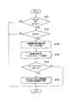
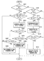
本第1実施形態の駆動制御システム100では、以上の処理をマイコン5に設けた磁石温度異常検出部30にて実施するようにしている。磁石温度異常検出部30が実施する処理のフローチャートを図4に示す。この図4のフローチャートで示す異常検出処理は、所定周期ごと(例えば1秒ごと)にマイコン5の割り込み処理として実施される。
In the
<ステップS101>
図4のフローがスタートすると、磁石温度異常検出部30は、まずステップS101において、第1電動機1に対応する電流指令値Idl*,Iql*と第2電動機2に対応する電流指令値Idr*,Iqr*がそれぞれ等しいか否かを判定する。<Step S101>
When the flow of FIG. 4 starts, the magnet temperature
<ステップS102>
そして、両電動機1,2に対応する電流指令値(即ち、Idl*とIdr*、Iql*とIqr*)がそれぞれ等しければ、次のステップS102において、第1電動機1の回転子回転速度Wlと第2電動機2の回転子回転速度Wrが等しいか否かを判定する。<Step S102>
If the current command values (ie, Idl * and Idr *, Iql * and Iqr *) corresponding to both the
<ステップS103>
両電動機1,2の回転子回転速度Wl,Wrが等しければ、次に、ステップS103において、第1電動機1に対応するq軸電圧指令値Vql*と第2電動機2に対応するq軸電圧指令値Vqr*との差分Vql*−Vqr*をもとに、両電動機1,2の鎖交磁束の差Φml−Φmrを求める。<Step S103>
If the rotor rotational speeds Wl and Wr of both the
<ステップS104>
そして、ステップS104において、前回の処理周期までに求めた過去の磁束差と今回の処理周期で求めた磁束差とから、磁束差の変化率d(|Φml−Φmr|)/dtを求める。<Step S104>
In step S104, the change rate d (| Φml−Φmr |) / dt of the magnetic flux difference is obtained from the past magnetic flux difference obtained up to the previous processing cycle and the magnetic flux difference obtained in the current processing cycle.
<ステップS105>
そして、ステップS105において、ステップS104で求めた磁束差の変化率d(|Φml−Φmr|)/dtの値が予め設定した所定閾値Sh1を越えるか否かを判定する。なお、第1電動機1及び第2電動機2の永久磁石の磁石温度と磁束差の変化率d(|Φml−Φmr|)/dtとの関係は、両電動機1,2の性能等に応じて決まるものであるため、実機を用いた実験等を事前に行って、所定閾値Sh1として最適な値を求めておけばよい。<Step S105>
In step S105, it is determined whether or not the value of the magnetic flux difference change rate d (| Φml−Φmr |) / dt obtained in step S104 exceeds a predetermined threshold value Sh1. The relationship between the magnet temperature of the permanent magnets of the first
<ステップS106>
このステップS105の判定の結果、磁束差の変化率d(|Φml−Φmr|)/dtが所定閾値Sh1を越えると判断した場合には、ステップS106において、第1電動機1と第2電動機2のうち少なくともいずれかの永久磁石に温度異常が発生していると判断し、例えばトルク指令値τ*を下方修正する等、永久磁石が不可逆減磁とならないための処理を行う。<Step S106>
As a result of the determination in step S105, if it is determined that the change rate d (| Φml−Φmr |) / dt of the magnetic flux difference exceeds the predetermined threshold value Sh1, then in step S106, the
なお、上記のステップS101、ステップS102、ステップS105のいずれかでNOと判定した場合は、今回の処理周期での異常検出処理を終了し、次の処理周期での異常検出処理が開始されるまで待機する。 In addition, when it determines with NO in any of said step S101, step S102, and step S105, the abnormality detection process in this process cycle is complete | finished, and the abnormality detection process in the next process period is started. stand by.
以上、具体的な例を挙げながら詳細に説明したように、本第1実施形態の電動車両の駆動制御システム100では、両電動機1,2において、対応する回転子回転速度ωe(即ち、ωelとωer)、対応する巻線電流Id,Iq(即ち、IdlとIdr、IqlとIqr)、対応する巻線インダクタンスLd,Lq(即ち、LdlとLdr、LqlとLqr)がそれぞれ同じ値という条件の下で、第1電動機1に対応するq軸電圧指令値Vql*と第2電動機2に対応するq軸電圧指令値Vqr*との差分Vql*−Vqr*をもとに、両電動機1,2の磁束差の変化率d(|Φml−Φmr|)/dtを求め、この磁束差の変化率d(|Φml−Φmr|)/dtが所定閾値Sh1を越える場合に、少なくともいずれかの電動機1,2の永久磁石に温度異常が発生していると判断するようにしている。したがって、この駆動制御システム100によれば、例えば電動車両が直進している場合のように左右輪が同一のトルク、同一の回転速度となっている際に、永久磁石の温度異常を高精度に検出することができる。その際、各電動機1,2の永久磁石の温度を温度センサなどで直接計測する必要は無い。
As described above in detail with specific examples, in the
また、両電動機1,2において、対応する回転子回転速度ωe(即ち、ωelとωer)、対応する巻線電流Id,Iq(即ち、IdlとIdr、IqlとIqr)、対応する巻線インダクタンスLd,Lq(即ち、LdlとLdr、LqlとLqr)がそれぞれ異なる場合であっても、巻線インダクタンスLd,Lq(即ち、LdlとLdr、LqlとLqr)の値が分かれば、上記の式(1)及び式(2)より、第1電動機1のq軸電圧Vqlと第2電動機2のq軸電圧Vqrとの差分Vql−Vqrから、両電動機1,2の鎖交磁束の差Φml−Φmrを求めることができる。ここで、巻線インダクタンスLd,Lqはd軸電流Idl,Idrやq軸電流Iql,Iqrに依存性があるため、d軸電流Idl,Idr及びq軸電流Iql,Iqrと巻線インダクタンスLd,Lqとの関係を示すマップを事前の実験等により作成して記憶させておくようにすれば、上述した例と同様に、第1電動機1に対応するq軸電圧指令値Vql*と第2電動機2に対応するq軸電圧指令値Vqr*との差分Vql*−Vqr*をもとに、両電動機1,2の磁束差の変化率d(|Φml−Φmr|)/dtを求めて、この磁束差の変化率d(|Φml−Φmr|)/dtと所定閾値Sh1との比較により、電動機1,2の永久磁石の温度異常を判定することが可能である。以上のように、本第1実施形態の電動車両の駆動制御システム100では、d軸電流Idl,Idr及びq軸電流Iql,Iqrと巻線インダクタンスLd,Lqとの関係を示すマップを記憶させておくことで、例えば電動車両の旋回時など、左右輪のトルクや回転速度が異なる場合であっても、永久磁石の温度異常を高精度に検出することができる。その際、各電動機1,2の永久磁石の温度を温度センサなどで直接計測する必要は無い。
In both
また、本第1実施形態の電動車両の駆動制御システム100では、両電動機1,2の磁束差の変化率d(|Φml−Φmr|)/dtを求め、この磁束差の変化率d(|Φml−Φmr|)/dtを所定閾値Sh1と比較することで、電動機1,2の永久磁石の温度異常を判定するようにしているので、電動機1,2のいずれか一方の永久磁石のみに温度異常が発生した場合だけでなく、双方の電動機1,2の永久磁石に同時に温度異常が発生した場合にも、その異常を検出することが可能である。
Further, in the
なお、電動車両が直進している場合のように、両電動機1,2において、対応する回転子回転速度ωe(即ち、ωelとωer)、対応する巻線電流Id,Iq(即ち、IdlとIdr、IqlとIqr)、対応する巻線インダクタンスLd,Lq(即ち、LdlとLdr、LqlとLqr)がそれぞれ同じ値という条件の下で電動機1,2の永久磁石の温度異常の判定を行う場合には、上記の式(3)から分かるように、両電動機1,2のq軸電圧Vql,Vqrの差分Vql−Vqrと両電動機1,2の鎖交磁束の差Φml−Φmrとが比例に近い関係で表される。したがって、この場合には、両電動機1,2の鎖交磁束の差Φml−Φmrを求めることなく、第1電動機1に対応するq軸電圧指令値Vql*と第2電動機2に対応するq軸電圧指令値Vqr*との差分Vql*−Vqr*の時間変化、つまり、両電動機1,2のq軸電圧Vql,Vqrの差分Vql−Vqrの時間変化の変化率d(|Vql−Vqr|)/dtを求め、このq軸電圧差の変化率d(|Vql−Vqr|)/dtが所定閾値Sh2を越える場合に、少なくともいずれかの電動機1,2の永久磁石に温度異常が発生していると判断するようにしてもよい。このように、両電動機1,2のq軸電圧差の変化率d(|Vql−Vqr|)/dtと所定閾値Sh2との比較により電動機1,2の永久磁石の温度異常を判定するようにした場合には、磁束差の変化率d(|Φml−Φmr|)/dtを所定閾値Sh1と比較して判定する場合と比べて判定の精度は若干劣るものの、両電動機1,2の鎖交磁束の差Φml−Φmrを求める演算が不要となる分、演算負荷の低減を図ることが可能となる。なお、第1電動機1及び第2電動機2の永久磁石の磁石温度とq軸電圧差の変化率d(|Vql−Vqr|)/dtとの関係は、両電動機1,2の性能等に応じて決まるものであるため、実機を用いた実験等を事前に行って、所定閾値Sh2として最適な値を求めておけばよい。
As in the case where the electric vehicle is traveling straight, in both
また、以上の例では、両電動機1,2の磁束差の変化率d(|Φml−Φmr|)/dtと所定閾値Sh1との比較、或いは、両電動機1,2のq軸電圧差の変化率d(|Vql−Vqr|)/dtと所定閾値Sh2との比較により、電動機1,2の永久磁石の温度異常を判定するようにしている。しかしながら、各値の時間変化の変化率を求めることなく、両電動機1,2の鎖交磁束の差分Φml−Φmrの値そのものを所定閾値Sh3と比較する、或いは、両電動機1,2のq軸電圧の差分Vql−Vqrの値そのものを所定閾値Sh4と比較することで、電動機1,2の永久磁石の温度異常を判定することも可能である。ただし、この場合の判定は、2つの電動機1,2のいずれか一方のみの温度が上昇して両電動機1,2の温度差が大きくなっている状況を判定するものとなる。
In the above example, the change rate d (| Φml−Φmr |) / dt of the magnetic flux difference between the
(第2実施形態)
次に、本発明の第2実施形態について説明する。本第2実施形態は、第1実施形態と同様にインバータ装置3が内蔵するマイコン5の一機能として本発明の異常検出装置が実現されており、制御構成は図1に示した第1実施形態と同様であるが、マイコン5に設けた磁石温度異常検出部30での処理が第1実施形態とは若干異なっている。すなわち、第1実施形態では、第1電動機1のq軸電圧Vqlと第2電動機2のq軸電圧Vqrとの差分Vql−Vqrを用いて磁石温度の異常を検出するようにしていたが、本第2実施形態では、両電動機1,2のq軸電圧の差分Vql−Vqrに加えてq軸電圧の比Vqr/Vqlも演算し、q軸電圧の差分Vql−Vqrとq軸電圧の比Vqr/Vqlの双方を用いて電動機1,2の永久磁石の温度異常を検出するようにしている。以下では、第1実施形態と異なる部分についてのみ説明する。(Second Embodiment)
Next, a second embodiment of the present invention will be described. In the second embodiment, the abnormality detecting device of the present invention is realized as one function of the microcomputer 5 built in the inverter device 3 as in the first embodiment, and the control configuration is the first embodiment shown in FIG. However, the processing in the magnet temperature
上記の式(1)と式(2)とから、第1電動機1のq軸電圧Vqlと第2電動機2のq軸電圧Vqrの比Vqr/Vqlをとると、下記式(4)が得られる。
When the ratio Vqr / Vql of the q-axis voltage Vql of the first
Vqr/Vql=(ωer・Ldr・Idr+Rr・Iqr+p・Lqr・Iqr+ωer・Φmr)/(ωel・Ldl・Idl+Rl・Iql+p・Lql・Iql+ωel・Φml) ・・・(4)
ここで、両電動機1,2の巻線電流Id,Iq(Idl,Iql;Idr,Iqr)がともに0という条件の下では、式(4)は下記の式(5)のように簡略化することができる。Vqr / Vql = ([omega] er.Ldr.Idr + Rr.Iqr + p.Lqr.Iqr + .omega.er..PHI.mr) / (. Omega.el.Ldl.Idl + Rl.Iql + p.Lql.Iql + .omega.el..PHI.ml) (4)
Here, under the condition that the winding currents Id and Iq (Idl, Iql; Idr, Iqr) of both the
Vqr/Vql=(ωer・Φmr)/(ωel・Φml) ・・・(5)
ここで、第1電動機1の永久磁石のみが温度上昇した場合には、第1電動機1の鎖交磁束Φmlが減少するため上記式(5)の分母が小さくなり、上記式(5)の値は1よりも大きくなる。一方、第2電動機2の永久磁石のみが温度上昇した場合には、第2電動機2の鎖交磁束Φmrが減少するため上記式(5)の分子が小さくなり、上記式(5)の値は1よりも小さくなる。したがって、上記式(5)の値が1よりも大きいか小さいかで、電動機1,2のうちのどちらの永久磁石の温度が高いかが分かり、第1電動機1の永久磁石の温度が高い場合は、式(5)の値が所定閾値よりも大きければ第1電動機1の永久磁石に温度異常が発生していると判断でき、第2電動機2の永久磁石の温度が高い場合は、式(5)の値が所定閾値を下回れば第2電動機2の永久磁石に温度異常が発生していると判断できる。Vqr / Vql = (ωer · Φmr) / (ωel · Φml) (5)
Here, when only the permanent magnet of the first
そこで、本第2実施形態の電動車両の駆動制御システム100では、両電動機1,2の巻線電流Id,Iq(Idl,Iql;Idr,Iqr)がともに0となるタイミングで、マイコン5に設けた磁石温度異常検出部30が、第1ベクトル制御部15の電流制御部18にて算出されるq軸電圧指令値Vql*と、第2ベクトル制御部25の電流制御部28にて算出されるq軸電圧指令値Vqr*とを用いて、両電動機1,2のq軸電圧の比Vqr/Vqlを演算する。そして、両電動機1,2のq軸電圧の比Vqr/Vqlの値が1よりも大きければその値が予め定めた所定閾値Sh5を越えている場合に、第1電動機1の永久磁石に温度異常が発生していると判断し、両電動機1,2のq軸電圧の比Vqr/Vqlの値が1よりも小さければその値が予め定めた所定閾値Sh6未満の場合に、第2電動機2の永久磁石に温度異常が発生していると判断する。そして、いずれかの電動機1,2の永久磁石に温度異常が発生していると判断した場合は、第1実施形態と同様に、トルク指令値τ*を低下させるなどの対応を図ることで、永久磁石の温度上昇によって不可逆減磁を起こして電動機の大幅な出力低下を招くといった事態を未然に回避する。
Therefore, in the
ただし、以上のような両電動機1,2のq軸電圧の比Vqr/Vqlを用いた演算では、特に分母側の値が微小であると演算誤差が大きくなり、判定精度が劣化する。そこで、両電動機1,2のq軸電圧の値に対する下限値(後述の「Vq_L」)を定めておき、磁石温度異常検出部30は、両電動機1,2のq軸電圧指令値Vql*,Vqr*がともに下限値(後述の「Vq_L」)以上の場合に限って両電動機1,2のq軸電圧の比を用いた永久磁石の温度異常の判定を行い、少なくともいずれかの電動機1,2のq軸電圧指令値Vql*,Vqr*が下限値(後述の「Vq_L」)未満の場合には、第1実施形態で説明したように、両電動機1,2のq軸電圧の差分Vql−Vqrを用いて永久磁石の温度異常の判定を行う。
However, in the calculation using the q-axis voltage ratio Vqr / Vql of both the
図5は、本第2実施形態の電動車両の駆動制御システム100において、マイコン5に設けた磁石温度異常検出部30にて実施される処理の流れを示すフローチャートである。この図5のフローチャートで示す異常検出処理は、所定周期ごと(例えば1秒ごと)にマイコン5の割り込み処理として実施される。
FIG. 5 is a flowchart showing a flow of processing performed by the magnet temperature
<ステップS201>
図5のフローがスタートすると、磁石温度異常検出部30は、まずステップS201において、第1電動機1に対応するq軸電圧指令値Vql*と第2電動機2に対応するq軸電圧指令値Vqr*との双方が下限値Vq_L以上となっているか否かを判定する。そして、q軸電圧指令値Vql*,Vqr*の双方が下限値Vq_L以上であればステップS202に進み、少なくともいずれか一方が下限値Vq_L未満であればステップS209に進む。<Step S201>
When the flow of FIG. 5 starts, the magnet temperature
<ステップS202>
ステップS202では、第1電動機1に対応する電流指令値Idl*,Iql*と第2電動機2に対応する電流指令値Idr*,Iqr*がともに0となっているか否かを判定する。<Step S202>
In step S202, it is determined whether or not the current command values Idl * and Iql * corresponding to the
<ステップS203>
そして、両電動機1,2に対する電流指令値(Idl*,Iql*;Idr*,Iqr*)がともに0となっていれば、次のステップS203において、第1電動機1に対応するq軸電圧指令値Vql*と第2電動機2に対応するq軸電圧指令値Vqr*とから、両電動機1,2のq軸電圧の比Vqr/Vqlを算出する。<Step S203>
If the current command values (Idl *, Iql *; Idr *, Iqr *) for both the
<ステップS204>
次に、ステップS204において、ステップS203で算出した両電動機1,2のq軸電圧の比Vqr/Vqlの値が1よりも大きいか否かを判定する。<Step S204>
Next, in step S204, it is determined whether or not the value of the q-axis voltage ratio Vqr / Vql of both the
<ステップS205>
そして、両電動機1,2のq軸電圧の比Vqr/Vqlの値が1よりも大きい場合は、ステップS205において、ステップS203で算出した両電動機1,2のq軸電圧の比Vqr/Vqlの値が予め定めた所定閾値Sh5を越えるか否かを判定する。<Step S205>
If the value of the q-axis voltage ratio Vqr / Vql of both the
<ステップS206>
そして、両電動機1,2のq軸電圧の比Vqr/Vqlの値が閾値Sh5を越える場合は、ステップS206において、第1電動機1の永久磁石に温度異常が発生していると判断して、例えばトルク指令値τ*を下方修正する等、永久磁石が不可逆減磁とならないための処理を行う。<Step S206>
If the value of the q-axis voltage ratio Vqr / Vql of both the
<ステップS207>
一方、両電動機1,2のq軸電圧の比Vqr/Vqlの値が1よりも小さい場合は、ステップS207において、ステップS203で算出した両電動機1,2のq軸電圧の比Vqr/Vqlの値が予め定めた所定閾値Sh6未満となっているか否かを判定する。<Step S207>
On the other hand, if the value of the q-axis voltage ratio Vqr / Vql of both the
<ステップS208>
両電動機1,2のq軸電圧の比Vqr/Vqlの値が閾値Sh6未満となっている場合は、ステップS208において、第2電動機2の永久磁石に温度異常が発生していると判断して、例えばトルク指令値τ*を下方修正する等、永久磁石が不可逆減磁とならないための処理を行う。<Step S208>
When the value of the q-axis voltage ratio Vqr / Vql of both the
なお、上記の閾値Sh5,Sh6としては、実機を用いた実験等を事前に行って最適な値を求めておけばよい。上記のステップS202、ステップS205、ステップS207のいずれかでNOと判定した場合は、今回の処理周期での異常検出処理を終了し、次の処理周期での異常検出処理が開始されるまで待機する。 In addition, what is necessary is just to obtain | require optimal value as said threshold value Sh5, Sh6 by conducting the experiment etc. which used the real machine in advance. If it is determined NO in any of the above steps S202, S205, and S207, the abnormality detection process in the current processing cycle is terminated, and the process waits until the abnormality detection process in the next processing cycle is started. .
また、上記のステップS201の判定で、第1電動機1に対応するq軸電圧指令値Vql*と第2電動機2に対応するq軸電圧指令値Vqr*のいずれか若しくは双方が下限値Vq_L未満となっていると判定してステップS209に進んだ場合、ステップS209以降の処理で、上述した第1実施形態と同様に、両電動機1,2のq軸電圧の差分Vql−Vqrを用いて永久磁石の温度異常の判定を行う。
In addition, in the determination in step S201, one or both of the q-axis voltage command value Vql * corresponding to the
<ステップS209>
すなわち、まずステップS209において、第1電動機1に対応する電流指令値Idl*,Iql*と第2電動機2に対応する電流指令値Idr*,Iqr*がそれぞれ等しいか否かを判定する。<Step S209>
That is, first, in step S209, it is determined whether or not the current command values Idl * and Iql * corresponding to the
<ステップS210>
そして、両電動機1,2に対応する電流指令値(即ち、Idl*とIdr*、Iql*とIqr*)がそれぞれ等しければ、次のステップS210において、第1電動機1の回転子回転速度Wlと第2電動機2の回転子回転速度Wrが等しいか否かを判定する。<Step S210>
If the current command values (ie, Idl * and Idr *, Iql * and Iqr *) corresponding to both the
<ステップS211>
両電動機1,2の回転子回転速度Wl,Wrが等しければ、次に、ステップS211において、第1電動機1に対応するq軸電圧指令値Vql*と第2電動機2に対応するq軸電圧指令値Vqr*との差分Vql*−Vqr*をもとに、両電動機1,2の鎖交磁束の差Φml−Φmrを求める。<Step S211>
If the rotor rotational speeds Wl and Wr of both the
<ステップS212>
そして、ステップS212において、前回の処理周期までに求めた過去の磁束差と今回の処理周期で求めた磁束差とから、磁束差の変化率d(|Φml−Φmr|)/dtを求める。<Step S212>
In step S212, the change rate d (| Φml−Φmr |) / dt of the magnetic flux difference is obtained from the past magnetic flux difference obtained up to the previous processing cycle and the magnetic flux difference obtained in the current processing cycle.
<ステップS213>
そして、ステップS213において、ステップS212で求めた磁束差の変化率d(|Φml−Φmr|)/dtの値が予め設定した所定閾値Sh1を越えるか否かを判定する。<Step S213>
In step S213, it is determined whether or not the value of the magnetic flux difference change rate d (| Φml−Φmr |) / dt obtained in step S212 exceeds a predetermined threshold value Sh1.
<ステップS214>
そして、ステップS213の判定の結果、磁束差の変化率d(|Φml−Φmr|)/dtが所定閾値Sh1を越えると判断した場合には、ステップS214において、第1電動機1と第2電動機2のうち少なくともいずれかの永久磁石に温度異常が発生していると判断し、例えばトルク指令値τ*を下方修正する等、永久磁石が不可逆減磁とならないための対応を実施する。<Step S214>
As a result of the determination in step S213, when it is determined that the rate of change d (| Φml−Φmr |) / dt of the magnetic flux difference exceeds the predetermined threshold value Sh1, the
なお、上記のステップS209、ステップS210、ステップS213のいずれかでNOと判定した場合は、今回の処理周期での異常検出処理を終了し、次の処理周期での異常検出処理が開始されるまで待機する。 In addition, when it determines with NO in any of said step S209, step S210, and step S213, the abnormality detection process in this process period is complete | finished, and the abnormality detection process in the next process period is started. stand by.
なお、以上の図5のフローチャートで示した例では、q軸電圧指令値Vql*,Vqr*の少なくともいずれかが下限値Vq_L未満の場合に、これらの差分Vql*−Vqr*をもとに両電動機1,2の磁束差の変化率d(|Φml−Φmr|)/dtを求め、この磁束差の変化率d(|Φml−Φmr|)/dtと閾値Sh1との比較により電動機1,2の永久磁石の温度異常を検出するようにしている(S213)。しかしながら、両電動機1,2の磁束差の変化率d(|Φml−Φmr|)/dtを閾値Sh1と比較するのではなく、第1実施形態で説明したように、両電動機1,2のq軸電圧差の変化率d(|Vql−Vqr|)/dtを閾値Sh2と比較する、或いは、両電動機1,2の鎖交磁束の差分Φml−Φmrの値そのものを閾値Sh3と比較する、或いは、両電動機1,2のq軸電圧の差分Vql−Vqrの値そのものを閾値Sh4と比較することで、電動機1,2の永久磁石の温度異常を検出するようにしてもよい。
In the example shown in the flowchart of FIG. 5 above, when at least one of the q-axis voltage command values Vql * and Vqr * is less than the lower limit value Vq_L, both of them are based on the difference Vql * −Vqr *. The rate of change d (| Φml−Φmr |) / dt of the magnetic flux difference of the
以上、具体的な例を挙げながら説明したように、本第2実施形態の電動車両の駆動制御システム100は、第1電動機1に対応するq軸電圧指令値Vql*と第2電動機2に対応するq軸電圧指令値Vqr*の双方が下限値Vq_L以上の場合には、両電動機1,2の巻線電流Id,Iq(Idl,Iql;Idr,Iqr)がともに0という条件の下で、両電動機1,2のq軸電圧の比Vqr/Vqlを用いて電動機1,2の永久磁石の温度異常を検出し、q軸電圧指令値Vql*,Vqr*の少なくともいずれかが下限値Vq_L未満の場合には、これらq軸電圧指令値Vql*,Vqr*の差分Vql*−Vqr*を用いて電動機1,2の永久磁石の温度異常を検出するようにしている。したがって、本第2実施形態の駆動制御システム100によれば、第1実施形態の駆動制御システム100と同様に、両電動機1,2の温度差が大きくなっている状況を判定する。従って、本第2実施形態の駆動制御システム100によれば、各電動機1,2の永久磁石の温度を温度センサなどで直接計測することなく、永久磁石の温度異常を高精度に検出することができる。
As described above with reference to specific examples, the
また、特に本第2実施形態の駆動制御システム100では、両電動機1,2のq軸電圧の比Vqr/Vqlを用いて電動機1,2の永久磁石の温度異常を検出することにより、バッテリ4の直流電圧Vdcの検出誤差の影響をキャンセルできるといった利点も得られる。すなわち、第1PWM制御部16や第2PWM制御部26で生成するPWM波形は、バッテリ4の直流電圧Vdcに対する電圧指令値の比に基づいて変調率を定めている。このため、バッテリ4の直流電圧Vdcに検出誤差が乗っていると、同じ変調率を得るための電圧指令値が変化してしまう。つまり、この場合、電圧指令値にはバッテリ4の直流電圧Vdcの検出誤差の影響が重畳されることになる。ここで、本第2実施形態の駆動制御システム100では、第1電動機1と第2電動機2の双方が1つのバッテリ4から電力を得ているので、両電動機1,2に対する電圧指令値には、同じだけの直流電圧Vdcの検出誤差の影響が重畳されていることになる。したがって、これら2つの電動機1,2に対する電圧指令値の比をとれば、直流電圧Vdcの検出誤差の影響をキャンセルすることができる。つまり、上記の式(5)の電圧比Vqr/Vqlには直流電圧Vdcの検出誤差の影響がキャンセルされている。バッテリ4の直流電圧Vdcに検出誤差が乗っている場合であっても、この値、即ち、両電動機1,2のq軸電圧の比Vqr/Vqlを用いて電動機1,2の永久磁石の温度異常を検出することにより、永久磁石の温度異常を高精度に検出することが可能となる。
In particular, in the
ところで、本第2実施形態のように、第1電動機1のq軸電圧Vqlと第2電動機2のq軸電圧Vqrとの差分Vql−Vqrと比Vqr/Vqlとを求める場合、上記の式(3)から両電動機1,2の鎖交磁束の差Φml−Φmrが求まり、式(5)から鎖交磁束の比Φmr/Φmlが求まるので、両電動機1,2の鎖交磁束の値Φml,Φmrそのものを算出することが可能となる。そして、両電動機1,2の鎖交磁束の値Φml,Φmrが分かれば、その値を反映させて各電動機1,2に対する電流指令値を算出することにより、トルク指令値τ*に対する実際の電動機1,2の出力トルクの追従性能を向上させることが可能となる。すなわち、各電動機1,2の磁石磁束が変化すると、一定の巻線電流を通電していても各電動機1,2が出力するトルクが変化してしまう。そこで、両電動機1,2の鎖交磁束の差Φml−Φmrと鎖交磁束の比Φmr/Φmlとから鎖交磁束の値Φml,Φmrそのものを算出し、算出した鎖交磁束の値Φml,Φmrを電流指令変換部6に入力する。そして、電流指令変換部6が、トルク指令値τ*と鎖交磁束の値Φml,Φmrとに基づいて電流指令値を決定することで、トルク指令値τ*に正確に追従したトルク出力が可能となる。なお、電流指令変換部6は、例えば、トルク指令値τ*及び磁石磁束とそれに対応するd軸電流指令値Idl*,Idr*及びq軸電流指令値Iql*,Iqr*との関係をマップ化して記憶しておくことにより、以上の処理を実現することができる。
By the way, when the difference Vql−Vqr and the ratio Vqr / Vql between the q-axis voltage Vql of the first
また、両電動機1,2のq軸電圧Vql,Vqrの差分Vql−Vqrと比Vqr/Vqlとから両電動機1,2の鎖交磁束の値Φml,Φmrそのものを算出した場合には、この鎖交磁束の値Φml,Φmrそのものを所定閾値Sh7と比較することで、電動機1,2の永久磁石の温度異常をさらに高精度に検出することが可能となる。
Further, when the interlinkage magnetic flux values Φml and Φmr themselves of both the
(第3実施形態)
次に、本発明の第3実施形態について説明する。本第3実施形態は、上述した第2実施形態と同様の手法により電動機1,2の永久磁石の温度異常を検出することを前提とし、両電動機1,2の巻線電流Id,Iq(Idl,Iql;Idr,Iqr)がともに0となるタイミングを積極的に設けることにより、q軸電圧の比Vqr/Vqlを用いた判定を可能とするシーンを増加させるようにしたものである。以下では、第2実施形態と異なる部分についてのみ説明する。(Third embodiment)
Next, a third embodiment of the present invention will be described. The third embodiment is based on the premise that the temperature abnormality of the permanent magnets of the
第2実施形態で説明した上記式(5)のように、両電動機1,2の巻線電流Id,Iq(Idl,Iql;Idr,Iqr)がともに0という条件の下では、上記式(4)の巻線抵抗Rや巻線インダクタンスLd,Lqの項を除去することができ、各電動機1,2のq軸電圧Vql,Vqrは磁石磁束(鎖交磁束)Φml,Φmrと比例の関係になる。したがって、磁石異常検出部30の処理に合わせて両電動機1,2の巻線電流Id,Iq(Idl,Iql;Idr,Iqr)がともに0となれば、両電動機1,2のq軸電圧の比Vqr/Vqlを用いた磁石温度の異常判定が可能となるシーンが増えるが、通常は、電動車両の駆動トルクは運転者のアクセル操作量に応じて決定されるため、両電動機1,2の巻線電流Id,Iq(Idl,Iql;Idr,Iqr)がともに0となるタイミングが磁石温度異常検出部30の処理周期(例えば1秒)ごとに定期的に生じるようなことはない。
As in the above equation (5) described in the second embodiment, under the condition that the winding currents Id and Iq (Idl, Iql; Idr, Iqr) of both the
そこで、本第3実施形態の電動車両の駆動制御システム100では、マイコン5の電流指令変換部6が、図6に示すように、トルク指令値τ*に対して実際に両電動機1,2が出力するトルクτの時間平均値は一致させ(即ち、トルクτの時間平均値をトルク指令値τ*に追従させ)つつ、両電動機1,2の巻線電流Id,Iq(Idl,Iql;Idr,Iqr)がともに0となる期間T0が形成されるように、各電動機1,2に対する電流指令値Id*,Iq*(Idl*,Iql*;Idr*,Iqr*)を生成する。そして、両電動機1,2の巻線電流Id,Iq(Idl,Iql;Idr,Iqr)がともに0となる期間T0を設ける周期ΔTperiodを例えば1秒毎とし、磁石温度異常検出部30による割り込み処理と同期させるようにする。これにより、磁石異常検出部30の処理に合わせて両電動機1,2の巻線電流Id,Iq(Idl,Iql;Idr,Iqr)がともに0となるタイミングが生じ、両電動機1,2のq軸電圧の比Vqr/Vqlを用いて磁石温度の異常判定を行うことが可能なシーンを増加させることができる。
Therefore, in the
以上のように、本第3実施形態の電動車両の駆動制御システム100によれば、マイコン5の電流指令変換部6が、実際に両電動機1,2が出力するトルクτの時間平均値をトルク指令値τ*に追従させつつ両電動機1,2の巻線電流Id,Iq(Idl,Iql;Idr,Iqr)がともに0となる期間T0が形成されるように、各電動機1,2に対する電流指令値Id*,Iq*(Idl*,Iql*;Idr*,Iqr*)を生成するようにしているので、電動機1,2の出力トルクが不用意に変動するといった不都合を生じさせずに、上述した第2実施形態による効果を最大限に発揮させることができる。
As described above, according to the
以上、本発明の具体的な実施形態として第1乃至第3実施形態を説明したが、これらの各実施形態は本発明の一適用例を例示的に示したものであり、本発明の技術的範囲がこれらの実施形態として開示した内容に限定されることを意図するものではない。つまり、本発明の技術的範囲は、上述した各実施形態で開示した具体的な技術事項に限らず、この開示から容易に導きうる様々な変形、変更、代替技術なども含むものである。 As described above, the first to third embodiments have been described as specific embodiments of the present invention. However, each of these embodiments is an example of application of the present invention, and the technical aspects of the present invention. It is not intended that the scope be limited to the details disclosed as these embodiments. That is, the technical scope of the present invention is not limited to the specific technical items disclosed in the above-described embodiments, but includes various modifications, changes, alternative techniques, and the like that can be easily derived from this disclosure.
日本国基礎出願である特願2009−198041号(日本国出願日:2009年8月28日)の全内容がここに援用され、誤訳や記載漏れから保護される。
The entire contents of Japanese Patent Application No. 2009-198041 (Japan filing date: August 28, 2009), which is a Japanese basic application, are incorporated herein and protected from mistranslations and omissions.
本発明によれば、永久磁石型同期電動機に対するq軸電圧指令値の差分を用いてこれら永久磁石型同期電動機の少なくともいずれかに磁石温度の異常が生じているか否かを判定するようにしている。従って、各永久磁石型同期電動機の永久磁石の温度を温度センサなどで直接計測することなく、電動車両用の電動機として用いられる永久磁石型同期電動機における磁石温度の異常を精度良く検出することができる。 According to the present invention, it is determined whether or not a magnet temperature abnormality has occurred in at least one of the permanent magnet type synchronous motors using the difference in the q-axis voltage command value for the permanent magnet type synchronous motor. . Therefore, it is possible to accurately detect abnormality of the magnet temperature in the permanent magnet type synchronous motor used as the electric motor for the electric vehicle without directly measuring the temperature of the permanent magnet of each permanent magnet type synchronous motor with a temperature sensor or the like. .
Claims (14)
前記複数の永久磁石型同期電動機に対する電流指令値を算出する電流指令値算出部と、
前記電流指令値算出部により各々算出された前記電流指令値に基づいて、前記複数の永久磁石型同期電動機に対するq軸電圧指令値を各々算出するq軸電圧指令値算出部と、
前記q軸電圧指令値算出部により算出された前記複数の永久磁石型同期電動機に対する前記q軸電圧指令値のうち、1つの永久磁石型同期電動機に対するq軸電圧指令値と他のいずれか1つの永久磁石型同期電動機に対するq軸電圧指令値との差分を用いて、前記永久磁石型同期電動機の少なくともいずれかに磁石温度の異常が生じているか否かを判定する磁石温度異常判定部と、
を備えることを特徴とする永久磁石型同期電動機の異常検出装置。 A plurality of permanent magnet synchronous motors;
A current command value calculation unit for calculating a current command value for the plurality of permanent magnet type synchronous motors;
A q-axis voltage command value calculation unit that calculates q-axis voltage command values for the plurality of permanent magnet synchronous motors based on the current command values respectively calculated by the current command value calculation unit;
Of the q-axis voltage command values for the plurality of permanent magnet type synchronous motors calculated by the q-axis voltage command value calculation unit, the q-axis voltage command value for one permanent magnet type synchronous motor and any one of the other. A magnet temperature abnormality determination unit that determines whether or not a magnet temperature abnormality has occurred in at least one of the permanent magnet type synchronous motors using a difference from a q-axis voltage command value for the permanent magnet type synchronous motor;
An abnormality detection device for a permanent magnet type synchronous motor, comprising:
前記磁石温度異常判定部は、前記電流指令値算出部により算出された前記電流指令値と前記記憶部に記憶されたマップとから前記複数の永久磁石型同期電動機の巻線インダクタンスを算出し、前記複数の永久磁石型同期電動機に対する前記q軸電圧指令値のうち、前記1つの永久磁石型同期電動機に対する前記q軸電圧指令値と前記他のいずれか1つの永久磁石型同期電動機に対する前記q軸電圧指令値との前記差分と、前記永久磁石型同期電動機の前記回転子回転速度と、前記永久磁石型同期電動機の前記巻線電流と、前記永久磁石型同期電動機の前記巻線インダクタンスとを用いて、前記永久磁石型同期電動機の前記鎖交磁束の前記差分を算出することを特徴とする請求項5又は6に記載の永久磁石型同期電動機の異常検出装置。 a storage unit storing a map indicating a relationship between the d-axis current and the q-axis current and the winding inductance;
The magnet temperature abnormality determination unit calculates winding inductances of the plurality of permanent magnet type synchronous motors from the current command value calculated by the current command value calculation unit and a map stored in the storage unit, Of the q-axis voltage command values for a plurality of permanent magnet type synchronous motors, the q-axis voltage command value for the one permanent magnet type synchronous motor and the q-axis voltage for any one of the other permanent magnet type synchronous motors. Using the difference from the command value, the rotor rotation speed of the permanent magnet type synchronous motor, the winding current of the permanent magnet type synchronous motor, and the winding inductance of the permanent magnet type synchronous motor The abnormality detection device for a permanent magnet type synchronous motor according to claim 5, wherein the difference of the interlinkage magnetic flux of the permanent magnet type synchronous motor is calculated.
前記電流指令値算出部は、前記複数の永久磁石型同期電動機に対するトルク指令値と、前記複数の永久磁石型同期電動機の前記鎖交磁束の前記値とに基づいて、前記複数の永久磁石型同期電動機に対する前記電流指令値を算出することを特徴とする請求項9乃至12のいずれか一項に記載の永久磁石型同期電動機の異常検出装置。 Based on the difference and the ratio of the q-axis voltage command values for the plurality of permanent magnet-type synchronous motors calculated by the q-axis voltage command value calculation unit, the interlinkage magnetic flux of each of the permanent magnet-type synchronous motors A flux linkage calculator for calculating the value of
The current command value calculation unit is configured to determine the plurality of permanent magnet type synchronization based on a torque command value for the plurality of permanent magnet type synchronous motors and the value of the linkage flux of the plurality of permanent magnet type synchronous motors. The abnormality detection device for a permanent magnet type synchronous motor according to any one of claims 9 to 12, wherein the current command value for the electric motor is calculated.
電流指令値算出作動により各々算出された前記電流指令値に基づいて、前記複数の永久磁石型同期電動機に対するq軸電圧指令値を各々算出する作動と、
前記q軸電圧指令値算出作動により算出された前記複数の永久磁石型同期電動機に対する前記q軸電圧指令値のうち、1つの永久磁石型同期電動機に対するq軸電圧指令値と他のいずれか1つの永久磁石型同期電動機に対するq軸電圧指令値との差分を用いて、前記永久磁石型同期電動機の少なくともいずれかに磁石温度の異常が生じているか否かを判定する作動と、
を備えることを特徴とする永久磁石型同期電動機の異常検出方法。 An operation for calculating a current command value for a plurality of permanent magnet type synchronous motors;
An operation for calculating q-axis voltage command values for the plurality of permanent magnet synchronous motors based on the current command values respectively calculated by current command value calculation operations;
Of the q-axis voltage command values for the plurality of permanent magnet type synchronous motors calculated by the q-axis voltage command value calculation operation, the q-axis voltage command value for one permanent magnet type synchronous motor and any one of the other An operation for determining whether or not a magnet temperature abnormality has occurred in at least one of the permanent magnet type synchronous motors using a difference from the q-axis voltage command value for the permanent magnet type synchronous motor;
An abnormality detection method for a permanent magnet type synchronous motor, comprising:
Priority Applications (1)
| Application Number | Priority Date | Filing Date | Title |
|---|---|---|---|
| JP2011528860A JP5331208B2 (en) | 2009-08-28 | 2010-08-27 | Abnormality detection device for permanent magnet type synchronous motor |
Applications Claiming Priority (4)
| Application Number | Priority Date | Filing Date | Title |
|---|---|---|---|
| JP2009198041 | 2009-08-28 | ||
| JP2009198041 | 2009-08-28 | ||
| PCT/JP2010/064554 WO2011024935A1 (en) | 2009-08-28 | 2010-08-27 | Anomaly detection device for a permanent magnet synchronous electric motor |
| JP2011528860A JP5331208B2 (en) | 2009-08-28 | 2010-08-27 | Abnormality detection device for permanent magnet type synchronous motor |
Publications (2)
| Publication Number | Publication Date |
|---|---|
| JPWO2011024935A1 JPWO2011024935A1 (en) | 2013-01-31 |
| JP5331208B2 true JP5331208B2 (en) | 2013-10-30 |
Family
ID=43628034
Family Applications (1)
| Application Number | Title | Priority Date | Filing Date |
|---|---|---|---|
| JP2011528860A Active JP5331208B2 (en) | 2009-08-28 | 2010-08-27 | Abnormality detection device for permanent magnet type synchronous motor |
Country Status (5)
| Country | Link |
|---|---|
| US (1) | US8791716B2 (en) |
| EP (1) | EP2472716B1 (en) |
| JP (1) | JP5331208B2 (en) |
| CN (1) | CN102484438B (en) |
| WO (1) | WO2011024935A1 (en) |
Families Citing this family (33)
| Publication number | Priority date | Publication date | Assignee | Title |
|---|---|---|---|---|
| WO2011142032A1 (en) * | 2010-05-14 | 2011-11-17 | 三菱電機株式会社 | Brushless-motor drive apparatus |
| TWI416151B (en) * | 2011-07-04 | 2013-11-21 | Delta Electronics Inc | Demagnetization detection device and demagnetization detection method thereof |
| JP5149431B2 (en) * | 2011-07-29 | 2013-02-20 | ファナック株式会社 | Temperature detection device that detects the temperature of the mover of the motor |
| JP5243651B2 (en) * | 2011-10-12 | 2013-07-24 | ファナック株式会社 | Motor control device for controlling d-axis current of permanent magnet synchronous motor |
| JP5886008B2 (en) * | 2011-11-18 | 2016-03-16 | Ntn株式会社 | Electric vehicle motor control device |
| JP5420006B2 (en) * | 2012-03-22 | 2014-02-19 | 三菱電機株式会社 | Synchronous machine controller |
| US9484791B2 (en) * | 2012-08-08 | 2016-11-01 | Infineon Technologies Ag | Remote rotor parameter sensor for electric drives |
| CN102841314A (en) * | 2012-09-21 | 2012-12-26 | 南车株洲电力机车研究所有限公司 | Temperature rise test method and system for electrically excited synchronous motors |
| US9628017B2 (en) | 2012-10-11 | 2017-04-18 | Mitsubishi Electric Corporation | Motor control device, and motor control method |
| JP5695013B2 (en) * | 2012-11-02 | 2015-04-01 | 本田技研工業株式会社 | Magnet temperature estimating apparatus and magnet temperature estimating method for rotating electrical machine |
| JP2014113977A (en) * | 2012-12-12 | 2014-06-26 | Toyota Motor Corp | Control unit of electric vehicle |
| JP5742879B2 (en) * | 2013-05-21 | 2015-07-01 | トヨタ自動車株式会社 | Rotating electric machine control device for vehicle |
| FR3006125B1 (en) * | 2013-05-21 | 2015-05-15 | Ifp Energies Now | METHOD AND SYSTEM FOR DETERMINING INTERNAL TEMPERATURES OF A SYNCHRONOUS ELECTRIC MACHINE USING STATE OBSERVERS |
| CN103439657B (en) * | 2013-07-23 | 2016-05-11 | 南京康尼机电股份有限公司 | AC servo motor transmission parameter detection method and the application in fault detect thereof |
| JP6211353B2 (en) | 2013-09-03 | 2017-10-11 | Ntn株式会社 | Electric vehicle control device |
| JP6245472B2 (en) * | 2013-12-26 | 2017-12-13 | 東海旅客鉄道株式会社 | Electric vehicle control device |
| CN104852356B (en) * | 2014-02-17 | 2018-09-21 | 伊顿公司 | The control protective unit of motor |
| EP2919026B1 (en) * | 2014-03-11 | 2021-10-27 | ABB Schweiz AG | Method and system for determining a synchronous machine fault condition |
| CN103956954B (en) * | 2014-03-27 | 2017-03-29 | 广东美的制冷设备有限公司 | The detection method and detection means of permanent-magnetic synchronous motor rotor demagnetization |
| DE102014220208A1 (en) * | 2014-10-07 | 2016-05-25 | Robert Bosch Gmbh | CONTROL DEVICE FOR AN ELECTRIC MACHINE, VEHICLE AND METHOD |
| KR102480750B1 (en) * | 2015-01-08 | 2022-12-27 | 삼성전자주식회사 | Motor driving apparatus and controlling method thereof |
| CN104700979B (en) * | 2015-03-30 | 2017-07-11 | 广东美芝制冷设备有限公司 | The demagnetization current detection method of compressor electric motor, device |
| CN106642516B (en) * | 2016-09-08 | 2019-07-16 | 四川长虹电器股份有限公司 | A kind of method and air-conditioning equipment detecting motor temperature |
| EP3382863B1 (en) * | 2017-03-30 | 2021-08-11 | ABB Schweiz AG | A method for detecting a rotor bar fault |
| JP6420405B1 (en) | 2017-05-02 | 2018-11-07 | ファナック株式会社 | Abnormality diagnosis apparatus and abnormality diagnosis method |
| KR101988333B1 (en) * | 2017-12-05 | 2019-06-12 | 장남철 | The Dual Brushless DC Motor with Single Controller |
| CN108173462B (en) * | 2017-12-13 | 2020-06-26 | 天津津航计算技术研究所 | Two-motor torque balance control method |
| JP6978602B2 (en) * | 2018-06-12 | 2021-12-08 | 株式会社日立製作所 | Permanent magnet synchronous motor drive, drive system and drive method |
| RU186188U1 (en) * | 2018-09-17 | 2019-01-11 | Федеральное государственное бюджетное образовательное учреждение высшего образования "Омский государственный университет путей сообщения" | Test bench for asynchronous machines |
| JP7312065B2 (en) * | 2019-09-11 | 2023-07-20 | 日立Astemo株式会社 | Motor control device, electromechanical integrated unit, generator system, motor drive device and electric vehicle system |
| CN112994575B (en) * | 2019-12-17 | 2023-01-31 | 青岛海尔空调电子有限公司 | Winding temperature determination method and starting method of three-phase compressor and air conditioner |
| KR20220156037A (en) * | 2020-03-20 | 2022-11-24 | 마그나 인터내셔널 인코포레이티드 | Determination of Permanent Magnet Flux Linkage for Permanent Magnet Synchronous Motors |
| CN114859223A (en) * | 2021-02-03 | 2022-08-05 | 台达电子工业股份有限公司 | Motor demagnetization detection method and motor demagnetization detection device |
Citations (3)
| Publication number | Priority date | Publication date | Assignee | Title |
|---|---|---|---|---|
| JP2004072931A (en) * | 2002-08-08 | 2004-03-04 | Nissan Motor Co Ltd | Controller for synchronous motor |
| JP2006014554A (en) * | 2004-06-29 | 2006-01-12 | Toyo Electric Mfg Co Ltd | Controller of permanent magnet synchronous motor |
| JP2007274779A (en) * | 2006-03-30 | 2007-10-18 | Aisin Aw Co Ltd | Electromotive drive control device, and electromotive drive control method |
Family Cites Families (10)
| Publication number | Priority date | Publication date | Assignee | Title |
|---|---|---|---|---|
| JP3496518B2 (en) * | 1998-06-10 | 2004-02-16 | 日産自動車株式会社 | Control device for rotating electric machine |
| JP4548886B2 (en) * | 1999-12-27 | 2010-09-22 | 東洋電機製造株式会社 | Control device for permanent magnet type synchronous motor |
| JP2002095300A (en) | 2000-09-19 | 2002-03-29 | Meidensha Corp | Method of controlling permanent magnet synchronous motor |
| DE10212751A1 (en) * | 2002-03-22 | 2003-10-02 | Bosch Gmbh Robert | Method and device for determining the rotor temperature in a PM synchronous machine |
| JP4023249B2 (en) * | 2002-07-25 | 2007-12-19 | ダイキン工業株式会社 | Compressor internal state estimation device and air conditioner |
| DE102005062588A1 (en) * | 2005-12-27 | 2007-06-28 | Robert Bosch Gmbh | Permanently excited synchronous machine`s magnet temperature determining method, involves measuring phase voltage and rotational speed of machine, and determining magnet temperature of machine from measured phase voltage and speed |
| US7595600B2 (en) | 2007-06-07 | 2009-09-29 | Gm Global Technology Operations, Inc. | Method and system for torque control in permanent magnet machines |
| JP2009072049A (en) * | 2007-09-18 | 2009-04-02 | Toshiba Corp | Electric vehicle controller |
| JP2009198041A (en) | 2008-02-20 | 2009-09-03 | Panasonic Corp | Air conditioner |
| US8421255B2 (en) * | 2009-10-28 | 2013-04-16 | General Electric Company | System and method for determining the temperature of a permanent magnet in a machine |
-
2010
- 2010-08-27 EP EP10811984.3A patent/EP2472716B1/en active Active
- 2010-08-27 US US13/391,860 patent/US8791716B2/en active Active
- 2010-08-27 CN CN201080038456.7A patent/CN102484438B/en active Active
- 2010-08-27 JP JP2011528860A patent/JP5331208B2/en active Active
- 2010-08-27 WO PCT/JP2010/064554 patent/WO2011024935A1/en active Application Filing
Patent Citations (3)
| Publication number | Priority date | Publication date | Assignee | Title |
|---|---|---|---|---|
| JP2004072931A (en) * | 2002-08-08 | 2004-03-04 | Nissan Motor Co Ltd | Controller for synchronous motor |
| JP2006014554A (en) * | 2004-06-29 | 2006-01-12 | Toyo Electric Mfg Co Ltd | Controller of permanent magnet synchronous motor |
| JP2007274779A (en) * | 2006-03-30 | 2007-10-18 | Aisin Aw Co Ltd | Electromotive drive control device, and electromotive drive control method |
Also Published As
| Publication number | Publication date |
|---|---|
| JPWO2011024935A1 (en) | 2013-01-31 |
| US20120146683A1 (en) | 2012-06-14 |
| US8791716B2 (en) | 2014-07-29 |
| WO2011024935A1 (en) | 2011-03-03 |
| CN102484438B (en) | 2015-04-01 |
| CN102484438A (en) | 2012-05-30 |
| EP2472716A4 (en) | 2017-05-24 |
| EP2472716B1 (en) | 2019-07-10 |
| EP2472716A1 (en) | 2012-07-04 |
Similar Documents
| Publication | Publication Date | Title |
|---|---|---|
| JP5331208B2 (en) | Abnormality detection device for permanent magnet type synchronous motor | |
| JP5130031B2 (en) | Position sensorless control device for permanent magnet motor | |
| US6188196B1 (en) | Electrical angle detecting apparatus and method, and motor control apparatus | |
| US9660560B2 (en) | Motor drive circuit and method of driving a motor | |
| EP3537601B1 (en) | Motor control method | |
| JP5396906B2 (en) | Electric motor drive control device | |
| US20070205743A1 (en) | Motor control device and motor control method | |
| JP2006254521A (en) | Control device of synchronous machine | |
| JP2007274779A (en) | Electromotive drive control device, and electromotive drive control method | |
| JP2015116021A (en) | Control device for permanent magnet synchronous motor | |
| JP4652176B2 (en) | Control device for permanent magnet type rotating electrical machine | |
| JP7361924B2 (en) | Motor control device, motor control method | |
| JP6287715B2 (en) | Rotating machine control device | |
| JP4781933B2 (en) | Electric motor control device | |
| JP2015211569A (en) | Synchronous machine control device | |
| JP2019122188A (en) | Motor control device and demagnetization determination circuit | |
| JP2010268599A (en) | Control device for permanent magnet motor | |
| JP5262267B2 (en) | Three-phase AC motor drive device | |
| JP5980456B1 (en) | Control apparatus and control method | |
| JP7180793B1 (en) | Motor control method and motor control device | |
| JP5854057B2 (en) | Step-out detection device and motor drive system | |
| JP7271954B2 (en) | motor controller | |
| JP2022116488A (en) | Device for estimating temperature of rotor magnet of permanent magnet synchronous motor, and method for estimating temperature of the rotor magnet | |
| JP5482625B2 (en) | Rotating machine control device | |
| JP2023177084A (en) | Control device for induction motor |
Legal Events
| Date | Code | Title | Description |
|---|---|---|---|
| TRDD | Decision of grant or rejection written | ||
| A01 | Written decision to grant a patent or to grant a registration (utility model) |
Free format text: JAPANESE INTERMEDIATE CODE: A01 Effective date: 20130716 |
|
| A61 | First payment of annual fees (during grant procedure) |
Free format text: JAPANESE INTERMEDIATE CODE: A61 Effective date: 20130726 |
|
| R150 | Certificate of patent or registration of utility model |
Ref document number: 5331208 Country of ref document: JP Free format text: JAPANESE INTERMEDIATE CODE: R150 Free format text: JAPANESE INTERMEDIATE CODE: R150 |