JP5330647B2 - Adaptive reference image generation - Google Patents
Adaptive reference image generation Download PDFInfo
- Publication number
- JP5330647B2 JP5330647B2 JP2006526923A JP2006526923A JP5330647B2 JP 5330647 B2 JP5330647 B2 JP 5330647B2 JP 2006526923 A JP2006526923 A JP 2006526923A JP 2006526923 A JP2006526923 A JP 2006526923A JP 5330647 B2 JP5330647 B2 JP 5330647B2
- Authority
- JP
- Japan
- Prior art keywords
- image
- reference image
- noise
- filter
- motion
- Prior art date
- Legal status (The legal status is an assumption and is not a legal conclusion. Google has not performed a legal analysis and makes no representation as to the accuracy of the status listed.)
- Active
Links
Images


Classifications
-
- H—ELECTRICITY
- H04—ELECTRIC COMMUNICATION TECHNIQUE
- H04N—PICTORIAL COMMUNICATION, e.g. TELEVISION
- H04N19/00—Methods or arrangements for coding, decoding, compressing or decompressing digital video signals
- H04N19/85—Methods or arrangements for coding, decoding, compressing or decompressing digital video signals using pre-processing or post-processing specially adapted for video compression
-
- H—ELECTRICITY
- H04—ELECTRIC COMMUNICATION TECHNIQUE
- H04N—PICTORIAL COMMUNICATION, e.g. TELEVISION
- H04N19/00—Methods or arrangements for coding, decoding, compressing or decompressing digital video signals
- H04N19/50—Methods or arrangements for coding, decoding, compressing or decompressing digital video signals using predictive coding
- H04N19/503—Methods or arrangements for coding, decoding, compressing or decompressing digital video signals using predictive coding involving temporal prediction
- H04N19/51—Motion estimation or motion compensation
-
- H—ELECTRICITY
- H04—ELECTRIC COMMUNICATION TECHNIQUE
- H04N—PICTORIAL COMMUNICATION, e.g. TELEVISION
- H04N19/00—Methods or arrangements for coding, decoding, compressing or decompressing digital video signals
- H04N19/10—Methods or arrangements for coding, decoding, compressing or decompressing digital video signals using adaptive coding
- H04N19/102—Methods or arrangements for coding, decoding, compressing or decompressing digital video signals using adaptive coding characterised by the element, parameter or selection affected or controlled by the adaptive coding
- H04N19/103—Selection of coding mode or of prediction mode
- H04N19/105—Selection of the reference unit for prediction within a chosen coding or prediction mode, e.g. adaptive choice of position and number of pixels used for prediction
-
- H—ELECTRICITY
- H04—ELECTRIC COMMUNICATION TECHNIQUE
- H04N—PICTORIAL COMMUNICATION, e.g. TELEVISION
- H04N19/00—Methods or arrangements for coding, decoding, compressing or decompressing digital video signals
- H04N19/46—Embedding additional information in the video signal during the compression process
-
- H—ELECTRICITY
- H04—ELECTRIC COMMUNICATION TECHNIQUE
- H04N—PICTORIAL COMMUNICATION, e.g. TELEVISION
- H04N19/00—Methods or arrangements for coding, decoding, compressing or decompressing digital video signals
- H04N19/60—Methods or arrangements for coding, decoding, compressing or decompressing digital video signals using transform coding
- H04N19/61—Methods or arrangements for coding, decoding, compressing or decompressing digital video signals using transform coding in combination with predictive coding
-
- H—ELECTRICITY
- H04—ELECTRIC COMMUNICATION TECHNIQUE
- H04N—PICTORIAL COMMUNICATION, e.g. TELEVISION
- H04N19/00—Methods or arrangements for coding, decoding, compressing or decompressing digital video signals
- H04N19/80—Details of filtering operations specially adapted for video compression, e.g. for pixel interpolation
- H04N19/82—Details of filtering operations specially adapted for video compression, e.g. for pixel interpolation involving filtering within a prediction loop
Description
本発明は、ビデオ・エンコーダ/ビデオ・デコーダ(CODEC)に向けられ、特に、CODECにおける予測子としての参照画像の使用に向けられる。 The present invention is directed to a video encoder / video decoder (CODEC), and in particular to the use of a reference picture as a predictor in the CODEC.
MPEG‐2およびJVT/H.264/MPEG AVCのような典型的ビデオ圧縮システムおよび規格においては、一般に、エンコーダとデコーダは、圧縮を達成するために、イントラ(intra)/インター(inter)コーディングに頼る。イントラ・コーディングでは、空間予測方法が使用され、インター・コーディングでは、画像間に存在する時間相関を利用することにより、圧縮が達成される。具体的に言うと、以前に符号化/復号化した画像が将来の画像のための参照画像として使用され、これらの画像間の動きを補償するために、動き推定および動き補償が行われる。H.264のような高度なCODECでは、必要なときに、より正確な予測を行うために、フェード・イン/フェード・アウトの間に、ライティング(lighting:照明)の変動を考慮する。最後に、予測/量子化プロセスで発生されるブロッキング・アーティファクト(blocking artifact)を減じるためにデブロッキング(deblocking)方法も使用される。 MPEG-2 and JVT / H. In typical video compression systems and standards such as H.264 / MPEG AVC, in general, encoders and decoders rely on intra / inter coding to achieve compression. In intra coding, spatial prediction methods are used, and in inter coding, compression is achieved by taking advantage of temporal correlation that exists between images. Specifically, previously encoded / decoded images are used as reference images for future images, and motion estimation and compensation are performed to compensate for motion between these images. H. Advanced CODECs such as H.264 consider lighting variations during fade-in / fade-out to make more accurate predictions when needed. Finally, a deblocking method is also used to reduce the blocking artifacts generated in the prediction / quantization process.
あいにく、インター・コーディング(inter coding)に関連する典型的方法では、予測プロセス全体にかなり影響する幾つかの付加的特性および特徴を考慮していない。特に高い解像度の画像は、フィルム粒子またはスペックル・ノイズ(speckle noise)のようなタイプのノイズを含んでいる。この種のノイズは、1つの画像と別の画像との間に全く相関関係を持たない傾向があり、符号化の間、参照画像内に残存するノイズを補償する必要が多分にある。このノイズのいくらかは、量子化により、またエンコーダに導入される非標準的な閾値化(non‐normative thresholding)により、除去されるが、それでもやはり符号化能率にかなり不利な影響を与える。 Unfortunately, typical methods associated with inter coding do not take into account some additional properties and features that significantly affect the overall prediction process. Particularly high resolution images contain types of noise such as film grain or speckle noise. This type of noise tends to have no correlation between one image and another, and there is often a need to compensate for noise remaining in the reference image during encoding. Some of this noise is removed by quantization and by non-normal thresholding introduced in the encoder, but it still has a significant adverse effect on coding efficiency.
時間/空間フィルタリング(filtering)方法を使用できる前処理の段階で、このノイズを除去して符号化能率をかなり改善できるが、フィルム・コンテンツの場合、ノイズ自体がフィルムの芸術的内容の一部でもあるので、このノイズをいくらか保持することも望ましい。従って、表示画像の芸術的内容を維持すると同時に、参照画像における相関性のないノイズを減じる新しいスキームが必要とされる。 In the pre-processing stage where temporal / spatial filtering methods can be used, this noise can be removed to significantly improve coding efficiency, but in the case of film content, the noise itself may be part of the artistic content of the film. It is also desirable to retain some of this noise because there is. Accordingly, a new scheme is needed that reduces the uncorrelated noise in the reference image while maintaining the artistic content of the displayed image.
(発明の概要)
従来技術のこれらのおよび他の欠点と不利な点は、適応参照画像の再生によるビデオ・コーディング/デコーディング(符号化/復号化)のための装置と方法により対処される。
(Summary of Invention)
These and other shortcomings and disadvantages of the prior art are addressed by an apparatus and method for video coding / decoding (encoding / decoding) through adaptive reference picture reproduction.
本発明は、参照専用の画像からの予測により、入力画像または画像ブロックを符号化して、付随的に復号化するビデオ・エンコーダとデコーダ、および対応する方法である。例示するエンコーダは、以前に符号化した画像を記憶する画像フレーム・バッファ、および画像フレーム・バッファに接続され、以前に符号化した画像から参照専用画像を発生する参照画像処理装置を具える。例示する符号化方法は、実質的に圧縮されない画像ブロックを受信するステップ、以前に符号化した画像をフィルタ処理して、適応参照画像を発生するステップ、適応参照画像を動き補償するステップ、圧縮されない画像ブロックから、動き補償された適応参照画像を差し引くステップ、および圧縮されない画像ブロックと動き補償された適応参照画像との差を符号化するステップから成る。 The present invention is a video encoder and decoder and corresponding method for encoding and concomitantly decoding an input image or image block by prediction from a reference-only image. The exemplary encoder comprises an image frame buffer for storing previously encoded images and a reference image processing device connected to the image frame buffer for generating a reference-only image from the previously encoded image. The exemplary encoding method includes receiving a substantially uncompressed image block, filtering a previously encoded image to generate an adaptive reference image, motion-compensating the adaptive reference image, and uncompressed. Subtracting the motion compensated adaptive reference image from the image block and encoding the difference between the uncompressed image block and the motion compensated adaptive reference image.
本発明のこれらのおよび他の特徴および利点は、図面に関連して読まれる実施例についての以下の説明から明らかとなる。 These and other features and advantages of the present invention will become apparent from the following description of embodiments read in conjunction with the drawings.
本発明の原理によれば、以前に符号化した画像にフィルタを適用し、それを、後に画像を符号化する際、参照用に使用して符号化能率の更なる改善が得られ、表示画像の芸術的内容の保持のために、符号化プロセスの間、ノイズ情報を維持するために使用できる。 In accordance with the principles of the present invention, a filter is applied to a previously encoded image, which can be used for reference later when encoding the image to provide further improvement in encoding efficiency, resulting in a display image. Can be used to maintain noise information during the encoding process to preserve the artistic content of the image.
本発明の幾つかの実施例の原理を説明する。本発明の実施例として明記または明示されていないが、当業者は、本発明の原理を具現化し且つ本発明の技術思想と範囲内に含まれる種々の構成を創案できるものと理解される。 The principle of several embodiments of the present invention will be described. Although not specified or explicitly described as examples of the present invention, it is understood that those skilled in the art can embody the principles of the present invention and create various configurations that fall within the spirit and scope of the present invention.
本明細書中に記載の実例および条件付き言語はすべて、当技術推進のため発明者より寄せられるコンセプトと本発明の原理を読者が理解するのを助ける教育上の目的を意図するものであり、明確に特定して記載されるこのような実例および条件に限定されるものではない。本発明の原理、態様、および実施例を記載する本明細書中のすべての記述、並びに本発明の具体的実例は、本発明の構造上および機能上の同等物を包含する意図のものである。加えて、このような同等物には、現在知られている同等物、および将来開発される同等物、構造に関りなく、同一の機能を実行する要素も含まれる。 All examples and conditional languages described herein are intended for educational purposes to assist the reader in understanding the concepts and principles of the present invention submitted by the inventors to promote the technology, It is not intended to be limited to such specific examples and conditions explicitly described. All statements herein reciting principles, aspects, and examples of the invention, as well as specific examples of the invention, are intended to encompass structural and functional equivalents of the invention. . In addition, such equivalents include those that perform the same function, regardless of currently known equivalents and equivalents and structures developed in the future.
ここに示すブロック図は、本発明の原理を具現化する例示的回路のコンセプトを表すことが当業者に理解されるであろう。フローチャート、流れ図、状態遷移図、擬似コードなどは、コンピュータで読み出されるメディア内に表され、コンピュータまたはプロセッサが明示されると否とに関らず、そのようなコンピュータまたはプロセッサで実行されるものと理解される。 It will be appreciated by those skilled in the art that the block diagrams shown herein represent exemplary circuit concepts embodying the principles of the invention. Flowcharts, flowcharts, state transition diagrams, pseudo code, etc. are represented in computer-readable media and executed on such computers or processors, whether or not the computer or processor is specified. Understood.
図面に示す種々の要素の機能は、専用のハードウェア、および適正なソフトウェアに関連してソフトウェアを実行できるハードウェアを使用して、提供される。プロセッサによって提供される場合、これらの機能は、単一の専用プロセッサによって、単一の共有プロセッサによって、あるいは複数の個々のプロセッサ(そのうち幾つかは共有される)によって、提供される。更に、「プロセッサ」または「コントローラ」という用語は、ソフトウェアを実行できるハードウェアのみを指すのではなく、DSP(ディジタル信号プロセッサ)ハードウェア、ソフトウェアを記憶するROM(読出し専用メモリ)、RAM(ランダムアクセス・メモリ)、および不揮発性メモリも含められる。 The functions of the various elements shown in the figures are provided using dedicated hardware and hardware capable of executing software in conjunction with appropriate software. When provided by a processor, these functions are provided by a single dedicated processor, by a single shared processor, or by multiple individual processors, some of which are shared. Furthermore, the terms “processor” or “controller” do not refer only to hardware capable of executing software, but to DSP (digital signal processor) hardware, ROM (read only memory) for storing software, RAM (random access). Memory), and non-volatile memory.
その他のハードウェア(従来の、またはカスタムの)も含められる。図面に示すスイッチは概念的なものにすぎない。これらのスイッチの機能は、プログラム・ロジックの動作を介して、専用のロジックを介して、プログラム制御と専用ロジックの相互作用を介して、あるいは手動により、実行され、特定の技術は、そのコンテクストから具体的に理解されるものとして実施者が選択できる。 Other hardware (conventional or custom) can also be included. The switches shown in the drawings are conceptual only. The function of these switches can be performed through the operation of program logic, through dedicated logic, through the interaction of program control and dedicated logic, or manually, and certain technologies are taken from that context. The practitioner can select what is specifically understood.
本発明の特許請求の範囲で、指定される機能を実行する手段として表される構成要素は、その機能を実行する方法を包含する意図のものであり、これには、例えば、a)その機能を実行する回路要素の組合せ、またはb)ソフトウェアを実行してその機能を実行するために適正な回路と組み合わされる、ファームウェア、マイクロコードなど任意の形態のソフトウェアが含まれる。特許請求の範囲で限定される本発明は、記載される種々の手段により提供される機能が特許請求の範囲で要求する方法で組み合わされ且つ統合されることに在る。従って出願者は、それらの機能を提供できる手段を、本明細書中に示す手段と同等のものと見なす。 In the claims of this invention, a component represented as a means for performing a specified function is intended to encompass a method for performing that function, for example, a) that function. Or b) any form of software, such as firmware, microcode, etc., combined with the appropriate circuitry to execute the software and perform its functions. The invention as defined in the claims is that the functions provided by the various means described are combined and integrated in the manner required by the claims. Applicant thus regards any means that can provide those functionalities as equivalent to those shown herein.
図1に、ビデオ・エンコーダを全体として参照番号100で示す。エンコーダ100への入力は、空間フィルタ102と入力画像ストア(記憶装置)104にそれぞれ接続される。空間フィルタ102の出力は、加算器110の切替え可能な非反転入力の第1の位置に切替え可能に接続される。入力画像ストア104はノイズ・リデューサ106に接続され、ノイズ・リデューサ106は、加算器110の切替え可能な非反転入力の第2の位置に接続される。加算器110の出力はブロック変成器120に接続され、変成器120は量子化器130に接続される。量子化器130の出力はエントロピ・コーダ/可変長コーダ(VLC)140に接続される。VLC140の出力はビデオ・エンコーダ100の外部で利用できる出力である。
In FIG. 1, a video encoder is indicated generally by the reference numeral 100. Inputs to the encoder 100 are connected to a
量子化器130の出力は更に逆量子化器150に接続される。逆量子化器150は逆ブロック変成器160に接続され、逆変成器160は、イン‐ループ(in‐loop)フィルタ172に接続され、イン‐ループ・フィルタ172は参照画像ストア175に接続される。参照画像ストア175の第1の出力は動き推定器/モード決定装置180の第1の入力に接続される。空間フィルタ102の出力は動き推定器180の第2の入力に接続される。動き推定器180の第1の出力は動き補償器190の第1の入力に接続される。動き推定器180の第2の出力はノイズ・リデューサ106の第2の入力に接続される。参照画像ストア175の第2の出力は動き補償器190の第2の入力に接続される。動き補償器190の出力は加算器110の反転入力に接続される。
The output of the
図2で、送信機201は受信機204に信号を伝達する。送信機201は、フィルム粒子除去装置211とフィルム粒子モデリング装置212を具え、装置211と212は入力ビデオ信号を受信する。フィルム粒子除去装置211は、フィルム粒子モデリング装置212とビデオ・エンコーダ213に接続され、ビデオ・エンコーダ213は受信機204のビデオ・デコーダに信号を伝達し、圧縮したビットストリームを送信する。フィルム粒子モデリング(modeling)装置212は、受信機204のフィルム粒子シミュレーション装置278に信号を伝達し、SEI(Supplemental Enhancement Information:補足的な付加情報)メッセージを送信する。ビデオ・デコーダ202は、フィルム粒子シミュレーション装置278と加算器282の第1の非反転入力の各々に接続される。フィルム粒子シミュレーション装置278は、加算器282の第2の非反転入力に接続され、加算器282は表示用の信号を供給する。
In FIG. 2,
受信機204は可変長デコーダ(VLD)210を具え、逆量子化器220に接続されるビットストリームを受信する。逆量子化器は逆ブロック変成器230に接続される。逆変成器は加算器240の第1の入力端子に接続される。加算器240の出力はループ・フィルタ272に接続され、ループ・フィルタ272はフレーム・バッファ274に接続される。フレーム・バッファ274は、動き補償器260、フィルム粒子シミュレーション装置278および加算器282の第1の非反転入力の各々に接続される。VLD210の出力は、第2の入力として動き補償器260に結合される。動き補償器260の出力は加算器240の第2の入力端子に接続される。フィルム粒子シミュレーション装置278は、例えば、補足的な付加情報(SEI)メッセージのような、ノイズ・パラメータを受信する第2の入力を有する。フィルム粒子シミュレーション装置278の出力は加算器282の第2の非反転入力に接続される。加算器282の出力は受信機282からの出力となる。
The
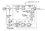
図3に、ビデオ・エンコーダを全体として参照番号300で示す。エンコーダ300への入力は加算器310の非反転入力に接続される。加算器310の出力はブロック変成器320に接続される。変成器320は量子化器330に接続され、量子化器330の出力は可変長コーダ(VLC)340に接続される。VLC340の出力は外部で利用できるエンコーダ300のビットストリーム出力である。
In FIG. 3, the video encoder is indicated generally by the reference numeral 300. The input to encoder 300 is connected to the non-inverting input of
量子化器330の出力は逆量子化器350に接続される。逆量子化器350は逆ブロック変成器360に接続され、逆変成器360は加算器370の第1の非反転入力に接続される。加算器370の出力はループ・フィルタ372に接続され、オプションで、参照画像処理装置376に接続される。ループ・フィルタ372はフレーム・バッファ374に接続され、フレーム・バッファ374は、参照画像処理装置376に接続され、オプションで、動き補償装置390に接続される。参照画像処理装置376は、可変長コーダ(VLC)340、フレーム・バッファ374、動き推定装置380、および動き補償装置390に接続される。
The output of the
エンコーダ300への入力は更に動き推定器380の第2の入力に接続される。動き推定器380の出力は、動き補償器390の入力、およびVLC340の第3の入力に接続される。動き補償器390の出力は加算器310の反転入力に接続される。
The input to encoder 300 is further connected to a second input of
図4に、ビデオ・デコーダを全体として参照番号400で示す。ビデオ・デコーダ400は可変長デコーダ(VLD)410を具え、逆量子化器420に接続されるビットストリームを受信する。逆量子化器420は逆変成器430に接続され、逆変成器430は加算器440の第1の入力端子に接続される。加算器440の出力はループ・フィルタ472に接続され、オプションで、ループ・フィルタ472でなく、参照画像処理装置476に接続され、ループ・フィルタを効果的にバイパスする。ループ・フィルタ472はフレーム・バッファ474に接続される。フレーム・バッファ474の第1の出力は参照画像処理装置476の第1の入力に接続される。VLD410は参照画像処理装置476の第2の入力に接続される。
In FIG. 4, the video decoder is indicated generally by the
参照画像処理装置476の第1の出力は動き補償装置460に接続され、動き補償装置460は、加算器440の第2の非反転入力端子に接続され、オプションで、参照画像処理装置476の入力に接続される。ビデオ・デコーダ400の出力は、フレーム・バッファ474の第2の出力と参照画像処理装置476の第2の出力に切替え可能に接続される。
The first output of the reference image processing device 476 is connected to the
図5に、画素の投影による参照画像の発生を全体として参照番号500で示す。各画素は、その以前の動きベクトルに応じて新しい位置に投影される。
In FIG. 5, the generation of a reference image by pixel projection is indicated by the
図6に、動きの投影による参照画像の発生を全体として参照番号600で示す。現在の参照画像における各ブロックは、共に位置づけされる(co‐located)ブロックと同じMV(Motion Vector:動きベクトル)を有するものと想定される。
In FIG. 6, the generation of a reference image by projection of motion is indicated by
図7に、本発明の原理による、適応参照画像発生により符号化するプロセスを示す。このプロセスは、スタート・ブロック710でコントロール(control:制御)を入力ブロック712に伝える。入力ブロック712は、圧縮されない画像ブロック・データを受信し、コントロールを機能ブロック714に伝え、機能ブロック714は、以前に符号化され記憶された画像にフィルタを適用し、適応参照画像を発生する。機能ブロック714はコントロールを機能ブロック718に伝え、機能ブロック718は、動きベクトルに対応して適応参照画像を補償し、コントロールを機能ブロック722に伝える。機能ブロック722は圧縮されない画像ブロックから動き補償された適応参照画像を差し引き、コントロールを機能ブロック724に伝える。機能ブロック724は、圧縮されない画像と動き補償された適応参照画像との差で信号を符号化し、コントロールを機能ブロック726に伝える。機能ブロック726は、復号化した差を動き補償された適応参照画像に加算して、復号化した画像を形成し、コントロールを機能ブロック728に伝える。機能ブロック728は復号化した画像を画像フレーム・バッファに記憶し、コントロールをエンド・ブロック730に伝える。
FIG. 7 illustrates a process for encoding with adaptive reference image generation according to the principles of the present invention. The process passes control to input block 712 at
図8に、本発明の原理による、適応参照画像の発生により復号化するプロセスを全体として参照番号800で示す。このプロセスは、スタート・ブロック810でコントロール(control:制御)を入力ブロック812に伝える。入力ブロック812は復号化した画像データを受信し、コントロールを機能ブロック814に伝える。機能ブロック814は、以前に符号化され記憶された画像にフィルタを適用して、適応参照画像を発生し、コントロールを機能ブロック816に伝える。機能ブロック816は適応参照画像を動き補償し、コントロールを機能ブロック818に伝える。機能ブロック818は符号化した差を復号化し、コントロールを機能ブロック824に伝える。機能ブロック824は、動き補償された適応参照画像を、復号化した差に加算し、復号化した画像を形成し、コントロールを機能ブロック826に伝える。機能ブロック826は復号化した画像を記憶し、表示し、コントロールをエンド・ブロック828に伝える。
In FIG. 8, a process for decoding by generating an adaptive reference picture according to the principles of the present invention is indicated generally by the
図1に戻り、ビデオ符号化/復号化アーキテクチャは、ビデオ・シーケンスからノイズを除去するために、空間/時間フィルタリング(filtering)のような、前処理方法を考慮してもよい。この処理は、本質的に、シーケンス内の空間/時間関係を改善し、よりよい符号化能率を導く。 Returning to FIG. 1, the video encoding / decoding architecture may consider preprocessing methods, such as spatial / temporal filtering, to remove noise from the video sequence. This process essentially improves the space / time relationship in the sequence and leads to better coding efficiency.
図2に関してよく理解されるように、場合によっては、保持することが望ましいタイプのノイズ(例えば、HD(高精細)コンテンツ内でのフィルム粒子ノイズ)もある。従って、このようなコンテンツを一組の符号化したパラメータに関連づけて、元のフィルム粒子ノイズの推定値をデコーダに発生させることも望ましい。これらのパラメータは、補足的な付加情報(SEI)メッセージと共にH.264で送信され、ノイズの発生のために、異なるモデルも使用することができる。 As is well understood with respect to FIG. 2, in some cases, there is also a type of noise that it is desirable to preserve (eg, film grain noise in HD (high definition) content). Therefore, it is also desirable to have the decoder generate an estimate of the original film grain noise by associating such content with a set of encoded parameters. These parameters, along with supplemental additional information (SEI) messages, Different models can also be used for noise generation, transmitted at H.264.
再び図3と図4に、現行の方法と比較して性能を更に改善できる新しい符号化/復号化アーキテクチャを示す。これは、表示用に符号化/復号化される画像と、将来符号化する画像のために参照用に使用される画像とを区別することにより達成される。コンテンツにも依るが、将来の画像の動き全体または一部を高い精度で予測できることは既に知られており、この情報を使用して、関連する参照画像を発生することができる。また、各画像について全く相関性のないタイプのノイズ(例えば、フィルム粒子ノイズ)もあり、このようなノイズは、よりよい符号化能率を達成するために、補償を要し、もしできるなら、参照画像から完全に除去する必要がある。 3 and 4 again show a new encoding / decoding architecture that can further improve performance compared to current methods. This is accomplished by distinguishing between images that are encoded / decoded for display and images that are used for reference for images to be encoded in the future. Depending on the content, it is already known that all or part of future image motion can be predicted with high accuracy, and this information can be used to generate related reference images. There are also non-correlated types of noise (eg film grain noise) for each image, such noise requires compensation to achieve better coding efficiency, and if it can be referenced It needs to be completely removed from the image.
ここに開示するアーキテクチャは、符号化/復号化のプロセスに付加的ステップを導入し、エンコーダとデコーダで利用できる既知の空間/時間情報を使用し、もし必要なら、復号化した画像を分析/処理し、将来の画像の参照基準として使用できる新しい画像を発生する。参照画像の発生手順は、ビットストリーム内の符号化された付加的情報に基づいて、あるいはコンテクストに基づいて適応的に決定される。この新しい画像は、ビットストリーム信号またはデコーダの決定に基づいて、表示の目的にも使用することができる。 The disclosed architecture introduces additional steps into the encoding / decoding process, uses known spatial / temporal information available at the encoder and decoder, and analyzes / processes the decoded image if necessary. And generate a new image that can be used as a reference for future images. The generation procedure of the reference image is adaptively determined based on the encoded additional information in the bitstream or based on the context. This new image can also be used for display purposes based on bitstream signal or decoder decisions.
本発明の原理により、現行のシステムと比較して符号化能率の更なる改善を導くインター予測(inter prediction)参照画像を発生するために、付加的ステップが符号化/復号化プロセスに導入される。ここに開示するシステムの特徴として、ノイズの多いコンテンツのシーケンスの場合、ノイズは通常、時間的に相関性がないので、以前に復号化された画像は最良の参照画像ではない。ノイズは前処理段階で除去できるが、フィルムのコンテンツにおけるフィルム粒子の場合のように、ノイズ自体が実際のコンテンツの一部でもあるので、ノイズを保持することが望ましいこともある。 In accordance with the principles of the present invention, an additional step is introduced into the encoding / decoding process to generate an inter prediction reference picture that leads to a further improvement in coding efficiency compared to current systems. . As a feature of the system disclosed herein, for a noisy sequence of content, the noise is usually not temporally correlated, so the previously decoded image is not the best reference image. Although the noise can be removed in the pre-processing stage, it may be desirable to retain the noise because the noise itself is also part of the actual content, as is the case with film grain in the film content.
このアーキテクチャにおいて、例えば、メディアン(median)フィルタ、ウイーナ(Wiener)フィルタ、幾何平均、最小二乗などのフィルタ、およびそれらの組合せを使用して、オプションの付加的フィルタリング・プロセスが各参照画像に適用される。フィルタリングを付加的に使用して、副画素(sub‐pixel)補間法で除去されないノイズを除去することができる。単純な平均化フィルタのような、線形フィルタも使用できるが、必ずしも副画素の位置を考慮する必要はない。時間フィルタリングのような、時間的方法を考慮し、あるいは以前の画像の動き情報を使用し、動き補償された参照画像を発生し、グローバルな動き補償により動き補償された新しい参照画像を発生することもできる。本明細書中で、簡略化のため、これらの方法は「フィルタリング(フィルタ処理)」(フィルタの使用)と称される。 In this architecture, an optional additional filtering process is applied to each reference image using, for example, median filters, Wiener filters, geometric mean, least squares, and combinations thereof. The Filtering can additionally be used to remove noise that is not removed by sub-pixel interpolation. A linear filter, such as a simple averaging filter, can also be used, but it is not necessary to consider the position of the subpixels. Consider temporal methods, such as temporal filtering, or use motion information from previous images to generate motion compensated reference images, and generate new motion compensated reference images with global motion compensation You can also. For simplicity, these methods are referred to herein as “filtering” (use of filters).
フィルタおよびプロセスは、すべての参照画像について固定されるが、異なるシステムに有益な、代りのアーキテクチャも幾つか使用できる。特に、簡単な方法として、1ビット信号のような、各画像の信号を符号化し、この画像が別の画像の参照基準とされるなら、フィルタ処理された画像が代りに使用される。この場合、原のサンプル、またはフィルタ処理されたサンプルを使用して副画素の位置が発生されることが、エンコーダとデコーダで予め定められる。代りに、この位置を指定する付加的信号を送信することができる。 Although the filters and processes are fixed for all reference images, several alternative architectures useful for different systems can also be used. In particular, if a simple method is to encode the signal of each image, such as a 1-bit signal, and this image is used as a reference for another image, the filtered image is used instead. In this case, it is predetermined by the encoder and decoder that the position of the sub-pixel is generated using the original sample or the filtered sample. Instead, an additional signal specifying this position can be transmitted.
各画像について、フィルタのパラメータおよび/または情報もストリーム内で送られる。この方法は、付加的メモリを必要としない明らかな利点を有するが、エンコーダの融通性も制限される。画像によっては、異なるフィルタを使用するか、または全く使用しない参照画像の方が有益となるであろう。 For each image, filter parameters and / or information are also sent in the stream. This method has the obvious advantage of not requiring additional memory, but also limits encoder flexibility. For some images, a reference image with different filters or none at all may be beneficial.
もっと融通性のある方法は、各画像について、その参照画像がフィルタ処理されるかどうかを指定する。この方法では、エンコーダを各画像の特性によりよく適応させ、より高い性能が達成される。すべての参照画像について同じフィルタを使用することができ、あるいはビットストリーム内で送られる各参照画像について異なるフィルタを使用することができる。画像には異なる特性を有する部分もあり、異なるフィルタリング方法から利益を得られることを考慮し、フィルタを使用せず、または異なるフィルタを使用して、同一画像を参照画像として再使用することもできる。バッファ内に現在の画像のための参照画像として使用できるN個の異なる画像、およびK個の異なるフィルタリング方法があるとすれば、基準として使用できる参照画像はN×(K+1)となる。フィルタは本質的に、マクロブロックのレベルで各参照画像に関連する参照指標(reference index)を介して選択され、これは、H.264で陽解法の(explicit)重みつき予測モードに現在行われているものに幾分類似する。 A more flexible method specifies for each image whether its reference image is filtered. In this way, the encoder is better adapted to the characteristics of each image and higher performance is achieved. The same filter can be used for all reference images, or a different filter can be used for each reference image sent in the bitstream. Considering that some images have different characteristics and can benefit from different filtering methods, the same image can be reused as a reference image without using a filter or with a different filter . If there are N different images in the buffer that can be used as reference images for the current image, and K different filtering methods, the reference image that can be used as a reference is N × (K + 1). The filter is essentially selected via a reference index associated with each reference image at the macroblock level, which is H.264 is somewhat similar to what is currently done in explicit weighted prediction mode.
もっと具体的に言うと、陽解法の重みつき予測で必要とされるパラメータは、符号化の間、画像およびスライス・ヘッダ内で送られる。例えば、画像ヘッダは、パラメータweighted_pred_flagとweighted_bipred_flagを含み、使用する重みつき予測モードを指定する。weighted_pred_flagが1であれば、PスライスとSPスライスについて、重みつき予測(常に陽解法)が使用される。weighted_bipred_flagも1であれば、Bピクチャについて陽解法の重みつき予測が使用される。これらのパラメータの何れかが1に設定され、適正なスライス・タイプが使用されるならば、予測重みテーブル(pred_weight_table)の諸要素もそのスライス・ヘッダ内で送信される。これらの要素には、スライスがBピクチャであり且つweighted_bipred_flagが1である(これは、各ブロックに関連する参照画像に依り異なるが、動き補償の間、予測サンプルの発生の間に使用される)なら、リスト_0とリスト_1に各参照画像についての重みとオフセットが含まれる。特定の参照画像に使用する特定の重みとオフセットは特定のマクロブロックまたはマクロブロック・パーティションの参照画像指標で表示される。 More specifically, the parameters required for explicit weighted prediction are sent in the image and slice headers during encoding. For example, the image header includes parameters weighted_pred_flag and weighted_bipred_flag, and specifies a weighted prediction mode to be used. If weighted_pred_flag is 1, weighted prediction (always explicit method) is used for P slices and SP slices. If weighted_bipred_flag is also 1, explicit weighted prediction is used for the B picture. If any of these parameters are set to 1 and the proper slice type is used, elements of the prediction weight table (pred_weight_table) are also transmitted in the slice header. For these elements, the slice is a B picture and the weighted_bipred_flag is 1 (this depends on the reference picture associated with each block, but is used during motion compensation and during the generation of prediction samples) If so, the list_0 and the list_1 include the weight and offset for each reference image. The specific weights and offsets used for a specific reference image are displayed with a reference image index for a specific macroblock or macroblock partition.
新しい予測方法とそのパラメータを同じヘッダ内に伝える、付加的要素を導入することもできる。例えば、adaptive_ref_pred_flagと名づけられる新しい画像レベルのシンタクス要素を規定することができる。もしこれが1であればスライス・ヘッダ内に付加的テーブル(例えば、adaptive_ref_table)が伝送され、テーブルは、どちらかのリストに各参照画像について付加的パラメータを含み、このリストには、フィルタリング方法とフィルタのパラメータが含まれる。フィルタのパラメータはダイナミックで、使用されるフィルタリング方法に依存する。例えば、メディアン・フィルタには付加的パラメータは必要でないが、分離可能なフィルタは、複数のタップと係数を必要とする。参照画像指標を使用して、特定のマクロブロックまたはマクロブロック・パーティションのために特定のフィルタを選択することができる。 Additional elements can be introduced that convey the new prediction method and its parameters in the same header. For example, a new image level syntax element named adaptive_ref_pred_flag may be defined. If this is 1, an additional table (eg, adaptive_ref_table) is transmitted in the slice header, and the table includes additional parameters for each reference image in either list, which includes the filtering method and filter Parameters are included. The filter parameters are dynamic and depend on the filtering method used. For example, median filters do not require additional parameters, but separable filters require multiple taps and coefficients. A reference image index can be used to select a particular filter for a particular macroblock or macroblock partition.
上述の方法は、付加的計算およびエンコーダとデコーダでの記憶を意味するが、フィルタ処理された値を瞬時に計算し、記憶の必要性を減じることもできる。これらの各参照画像について副画素値を計算することは必ずしも必要でなく、オリジナル(原画像)から生じた副画素値のみを計算し記憶することにより、このようなエンコーダの複雑性が減じられる。この場合、フィルタ処理された参照画像の副画素値を原の副画素値と同じにさせる(これはRate Distortion Optimizationモデルの下で有益である)か、またはフィルタ処理された参照画像について整数の動きベクトル与えることもできる。このような場合、これらの動きベクトルは、動きベクトル予測プロセスの間、適正にスケール化する必要があり、それらの予測子は最も近い整数値に四捨五入すべきである。 While the above method implies additional computation and storage at the encoder and decoder, the filtered values can be calculated instantaneously, reducing the need for storage. It is not necessary to calculate the subpixel values for each of these reference images, and by calculating and storing only the subpixel values that originate from the original (original image), the complexity of such an encoder is reduced. In this case, the sub-pixel value of the filtered reference image is made the same as the original sub-pixel value (this is beneficial under the Rate Distortion Optimization model), or an integer motion for the filtered reference image Vectors can also be given. In such a case, these motion vectors need to be properly scaled during the motion vector prediction process and their predictors should be rounded to the nearest integer value.
参照画像の発生に使用されるフィルタを示す信号を送るかどうかはさておき、復号化したマクロブロックまたはモードの特性を与えられれば、このような決定をマクロブロックのレベルで行うこともできる。Pピクチャ用のSKIPまたはBピクチャ用のDirectまたはBi‐predictive(双方向予測)のようなモードは、大抵のシーケンスで、フィルタ処理されない画像から利益を得るように思われる。例えば、SKIPが使用されると、これは、現在のマクロブロックはその参照画像との類似性が非常に高いことを、そしてたとえノイズがいくらか存在しても、視覚に著しく影響しないことを意味する。同じことは、DirectSKIPにも当てはまり、Directを含むすべての双方向予測モードはそれ自体、時間フィルタとして働き、多量のノイズを減じることができる。他方、これらのモードにフィルタ処理された画像を使用すると、付加的フィルタリングにより、ぼけのような、アーティファクトを多く生じて能率を低下させる。 Aside from sending a signal indicating the filter used to generate the reference picture, such a decision can also be made at the macroblock level, given the characteristics of the decoded macroblock or mode. Modes such as SKIP for P pictures or Direct or Bi-predictive (Bi-predictive) for B pictures appear to benefit from unfiltered images in most sequences. For example, when SKIP is used, this means that the current macroblock is very similar to its reference image and does not significantly affect vision even if some noise is present. . The same is true for DirectSKIP, where all bi-directional prediction modes including Direct themselves act as temporal filters and can reduce a lot of noise. On the other hand, the use of filtered images for these modes results in additional artifacts, such as blurring, and reduced efficiency due to additional filtering.
図3および図4はそれぞれ、エンコーダとデコーダを示す。このエンコーダとデコーダに含まれるユニークな要素は参照画像処理モジュールである。図3から、デブロッキング(deblocking)前後の画像から参照画像を発生することが可能であり、フィルタリングは必須のものではない。以前符号化した画像からの動き情報も、動き投影された参照画像の発生に使用できる。H.264で使用されるtemporal directと同様、動きは隣接する画像間で相対的に連続していることを考慮することにより、この参照画像は発生される。この観察で、画素の投影を使用して、参照画像が発生され、図5に示すように、各画素はその以前の動きベクトルに従って新しい位置に投影され、あるいは図6に示すように、動きを投影して、現在の参照画像における各マクロブロックは、それと同時に位置づけされるブロックと同じ動きベクトル(MV)を有するものと想定される。重みつき平均を使用して2つの方法を組み合わせることもでき、投影された画素を、他の方法でフィルタ処理することもできる。拡張処理法として、マルチスペクトル画像エンハンスメントにおけるのと同様な方法を使用することもでき、この場合、動き/画素の投影またはフィルタリングにより、複数の画像が組み合わされ、超(スーパー)解像度のイメージングまたは顕著な静止画に匹敵する単一の参照画像が発生される。 3 and 4 show an encoder and a decoder, respectively. A unique element included in the encoder and decoder is a reference image processing module. From FIG. 3, it is possible to generate a reference image from images before and after deblocking, and filtering is not essential. Motion information from previously encoded images can also be used to generate motion projected reference images. H. As with the temporal direct used in H.264, this reference image is generated by considering that the motion is relatively continuous between adjacent images. In this observation, a reference image is generated using the projection of the pixels, and each pixel is projected to a new position according to its previous motion vector, as shown in FIG. 5, or a motion as shown in FIG. Projecting, each macroblock in the current reference image is assumed to have the same motion vector (MV) as the block located at the same time. The weighted average can be used to combine the two methods, and the projected pixels can be filtered in other ways. As an extended processing method, a method similar to that in multispectral image enhancement can also be used, where multiple images are combined by motion / pixel projection or filtering to produce super (super) resolution imaging or salient A single reference image comparable to a still image is generated.
例示するフィルタには以下のものが含まれる:a)1×3、b)3×1、c)分離可能(最初に1×3それに続いて3×1)、d)3×3メディアン、f)それらの重みつき平均と原の参照画像(ref=(a×Med1×3+b×Med3×1+c×Med3×3+d×オリジナル+(a+b+c+d)/2)/(a+b+c+d))、g)wienerフィルタ(Gaussianノイズの処理による)、h)係数付きa3×3平均化フィルタ、

またはi)簡単な分離可能n‐タップ・フィルタ、j)閾値化された平均(結果が原のサンプルとかなり異なるなら、フィルタhのみを使用する)、およびこれらのフィルタの組合せ。他のフィルタも使用され、ビットストリーム内に送られ、またはエンコーダとデコーダ内で知られ、ビットストリーム内のパラメータを介して、例えば、参照指標を介して、選択される。
Exemplary filters include: a) 1 × 3, b) 3 × 1, c) separable (first 1 × 3 followed by 3 × 1), d) 3 × 3 median, f ) The weighted average and the original reference image (ref = (a × Med 1 × 3 + b × Med 3 × 1 + c × Med 3 × 3 + d × original + (a + b + c + d) / 2) / (a + b + c + d)), g ) Wiener filter (by Gaussian noise processing), h) a3 × 3 averaging filter with coefficients,
Or i) a simple separable n-tap filter, j) a thresholded average (if the result is significantly different from the original sample, use only filter h), and a combination of these filters. Other filters are also used and sent in the bitstream or known in the encoder and decoder and selected via parameters in the bitstream, for example via a reference indicator.
このアーキテクチャでも使用され且つ簡単な3×3メディアン(Median)よりもよいエッジを維持する、比較的複雑性の低い、かなり興味あるフィルタは、2‐Dオーダの統計フィルタとメディアンの組合せであった。原(オリジナル)画像内にある現在の画素とその周囲の8画素が選択され分類された。もし現在の画素が3×3メディアンと同じであったなら、他の処理は行われなかった。もし同じでなく、現在の画素が最大または最小のサンプルであったなら、これは、それに最も近いサンプルで置き換えられたか、またはそれに最も近いサンプルとそれ自体との平均で置き換えられた。そのほか、このサンプルは現在のサンプルとそれに最も近い2つのサンプルの平均値で置き換えられた。 A relatively low complexity, fairly interesting filter used in this architecture and maintaining better edges than the simple 3x3 Median was a combination of a 2-D order statistical filter and a median. . The current pixel and the surrounding 8 pixels in the original image were selected and classified. If the current pixel was the same as a 3x3 median, no other processing was performed. If not the same and the current pixel was the largest or smallest sample, it was replaced with the sample closest to it or replaced with the average of the sample closest to it and itself. In addition, this sample was replaced with the average value of the current sample and the two closest samples.
同じ参照画像を発生し且つドリフトを回避するために、デコーダはどのフィルタが使用されたかを正確に知らなければならない。エンコーダとデコーダで、このフィルタは同一であり、このフィルタをピクチャまたはスライス・レベルで伝送することもできる。このフィルタ全体をMB(マクロブロック)レベルで伝送するにはかなりの経費を要することになるが、もしフィルタがグローバルな動き補償された参照画像を使用しており且つ付加的融通性が得られるなら、動きベクトル(MV)スケーリング・パラメータのような、フィルタの一部を調節する追加的パラメータを幾つか伝送することもできる。エンコーダは、複雑性が最小の適正な処理方法を選択できなければならない。この目的で、ノイズ推定、画像相関などのような、参照画像と現在の画像の事前分析法も使用される。このような推定は、画像全体のレベルで、あるいは異なる領域で(特に、異なるエリアは、領域に基づく方法で、より正確に検出できる異なる特性を有することを考慮する際に)、行われる。 In order to generate the same reference image and avoid drift, the decoder must know exactly which filter was used. In the encoder and decoder, this filter is identical and this filter can also be transmitted at the picture or slice level. It would be quite expensive to transmit this entire filter at the MB (macroblock) level, but if the filter uses a global motion compensated reference image and additional flexibility is gained Some additional parameters that adjust part of the filter, such as motion vector (MV) scaling parameters, can also be transmitted. The encoder must be able to select an appropriate processing method with minimal complexity. For this purpose, a pre-analysis method of the reference image and the current image, such as noise estimation, image correlation, etc., is also used. Such estimation is performed at the level of the entire image or at different regions (especially when considering that different areas have different characteristics that can be detected more accurately in a region-based manner).
本発明のこれらのおよびその他の特徴と利点は、本明細書中における教示に基づいて当技術に通常の技量を有する者に容易に確かめられる。本発明の原理は、種々の形態のハードウェア、ソフトウェア、ファームウェア、特殊目的のプロセッサ、またはそれらを組み合わせて実施されることが理解されるべきである。 These and other features and advantages of the present invention will be readily ascertainable to one of ordinary skill in the art based on the teachings herein. It should be understood that the principles of the invention may be implemented in various forms of hardware, software, firmware, special purpose processors, or combinations thereof.
本発明の原理は、ハードウェアとソフトウェアを組み合わせて実施されるのが最も好ましい。ソフトウェアは、プログラム記憶装置で具現化されるアプリケーション・プログラムとして実施されるのが好ましい。アプリケーション・プログラムは適当なアーキテクチャを具えるマシンにアップロードされ、マシンで実行される。マシンは、一個または複数個の中央処理装置(CPU)、ランダム・アクセス・メモリ(RAM)、および入力/出力(I/O)インタフェースを有するコンピュータ・プラットフォームで実施されるのが好ましい。コンピュータ・プラットフォームにはオペレーティング・システムとマイクロインストラクション・コードを含んでいる。本明細書中に記載の種々のプロセスと機能はマイクロインストラクション・コードの一部であるか、またはアプリケーション・プログラムの一部であり、またはその組合せであり、CPUで実行される。付加的データ記憶装置およびプリンタのような種々の周辺装置がコンピュータ・プラットフォームに接続される。 The principles of the present invention are most preferably implemented using a combination of hardware and software. The software is preferably implemented as an application program embodied in a program storage device. The application program is uploaded to a machine with an appropriate architecture and executed on the machine. The machine is preferably implemented on a computer platform having one or more central processing units (CPUs), a random access memory (RAM), and input / output (I / O) interfaces. The computer platform includes an operating system and microinstruction code. The various processes and functions described herein are part of the microinstruction code, or part of the application program, or a combination thereof, and are executed by the CPU. Various peripheral devices such as additional data storage devices and printers are connected to the computer platform.
図面に描かれるシステムの構成部品および方法の幾つかはソフトウェアで実施されるのが好ましく、システム構成部品またはプロセス機能ブロック間の実際の接続は、本発明がプログラムされる仕方に依り異なる。本明細書中における教示を与えられれば、当業者は本発明のこれらのおよび類似の実施または構成を考えることができるであろう。 Some of the system components and methods depicted in the drawings are preferably implemented in software, and the actual connections between system components or process functional blocks will depend on how the invention is programmed. Given the teachings herein, one of ordinary skill in the related art will be able to contemplate these and similar implementations or configurations of the present invention.
実施例は図面に関して説明されているが、本発明はそれらの厳密な実施例に制限されず本発明の技術思想または範囲から離脱することなく、当技術に通常の技量を有する者により種々の変更および変形が可能であることが理解されるべきである。そのような変更および変形はすべて、特許請求の範囲に記載の本発明の範囲内に含められる意図のものである。 While the embodiments have been described with reference to the drawings, the invention is not limited to those precise embodiments and various modifications may be made by those having ordinary skill in the art without departing from the spirit or scope of the invention. It should be understood that variations are possible. All such changes and modifications are intended to be included within the scope of the present invention as set forth in the appended claims.
Claims (14)
以前に符号化し再構成した少なくとも1つの画像を記憶する画像フレーム・バッファと、
前記画像フレーム・バッファに接続され、前記以前に符号化し再構成した少なくとも1つの画像をフィルタ処理して時間的に相関関係のないノイズを減らすことによって、少なくとも1つの参照画像を発生する参照画像処理装置であって、該時間的に相関関係のないノイズが、前記以前に符号化し再構成した少なくとも1つの画像に符号化される少なくとも一つの入力画像に含まれるノイズによって生じる、該参照画像処理装置と、
を具える、前記ビデオ・エンコーダ。 A video encoder that encodes the input image to preserve noise information in the input image, predicted from at least one reference image,
An image frame buffer for storing at least one previously encoded and reconstructed image;
A reference image connected to the image frame buffer and generating at least one reference image by filtering the previously encoded and reconstructed at least one image to reduce temporally uncorrelated noise A processing apparatus , wherein the temporally uncorrelated noise is caused by noise contained in at least one input image encoded into the previously encoded and reconstructed at least one image Equipment ,
Said video encoder.
時間的に相関関係のないノイズを含む圧縮しない画像ブロックを受信するステップと、
以前に符号化し再構成した画像をフィルタ処理して時間的に相関関係のないノイズを減らして適応参照画像を生成するステップであって、前記以前に符号化し再構成した画像中の該時間的に相関関係のないノイズが、該以前に符号化し再構成した画像に符号化される入力画像中のノイズによって生じる、該ステップと、
前記適応参照画像を動き補償するステップと、
前記動き補償した適応参照画像と前記圧縮しない画像ブロックとの差を求めるステップと、
前記圧縮しない画像ブロックと動き補償した適応参照画像との間の差を符号化するステップと、
を含む、前記方法。 A method of encoding the video signal data for an image block so as to retain noise information in the video signal data by a video encoder,
Receiving an uncompressed image block containing temporally uncorrelated noise;
Filtering the previously encoded and reconstructed image to reduce temporally uncorrelated noise and generating an adaptive reference image, the temporal encoding in the previously encoded and reconstructed image Noise caused by noise in the input image encoded in the previously encoded and reconstructed image; and
Motion compensating the adaptive reference picture;
A step asking you to differences between image blocks without the compressed adaptive reference image the motion compensation,
A step of encoding a difference between the adaptive reference picture image blocks and motion compensation without the compression,
Said method.
以前に復号化した少なくとも1つの画像を記憶する画像バッファと、
前記画像バッファに接続され、前記以前に復号化した少なくとも1つの画像を時間的に相関関係のないノイズを減らすためにフィルタ処理することによって、前記少なくとも1つの参照画像を発生する参照画像処理装置と、
を具え、
該少なくとも1つの参照画像は、表示のために使用されない、前記ビデオ・デコーダ。 A video decoder for decoding the output image to retain noise information in the input image corresponding to the output image, predicted from at least one reference image,
An image buffer for storing at least one previously decoded image;
Connected to said image buffer, by filtering to reduce at least one image temporally uncorrelated noise decrypted to previous and said at least one reference image reference image processing apparatus for generating a ,
With
The video decoder, wherein the at least one reference image is not used for display.
符号化された画像データを受信するステップと、
前記符号化された画像データから予測誤差を復号化するステップと、
以前に復号化した画像に時間的に相関関係のないノイズを減らすためにフィルタを適用して参照画像を発生させるステップと、
前記参照画像を動き補償して動き補償した参照画像を発生するステップと、
前記動き補償した参照画像を前記予測誤差に加算して復号化した画像を形成するステップと、
前記復号化した画像を表示画像として表示するステップと、
を含む、前記方法。 A method of decoding the video signal data to retain noise information in the video signal data by a video decoder for a display image,
Receiving encoded image data; and
Decoding a prediction error from the encoded image data;
A step of previously generating a reference image by applying a filter to reduce the no noise temporally correlated to the decoded image,
And generating a reference image motion compensating the reference image and motion compensation,
Adding the motion compensated reference image to the prediction error to form a decoded image;
Displaying the decoded image as a display image;
Said method.
Applications Claiming Priority (3)
| Application Number | Priority Date | Filing Date | Title |
|---|---|---|---|
| US50457503P | 2003-09-17 | 2003-09-17 | |
| US60/504,575 | 2003-09-17 | ||
| PCT/US2004/028650 WO2005034517A1 (en) | 2003-09-17 | 2004-09-02 | Adaptive reference picture generation |
Publications (3)
| Publication Number | Publication Date |
|---|---|
| JP2007506361A JP2007506361A (en) | 2007-03-15 |
| JP2007506361A5 JP2007506361A5 (en) | 2007-10-18 |
| JP5330647B2 true JP5330647B2 (en) | 2013-10-30 |
Family
ID=34421519
Family Applications (1)
| Application Number | Title | Priority Date | Filing Date |
|---|---|---|---|
| JP2006526923A Active JP5330647B2 (en) | 2003-09-17 | 2004-09-02 | Adaptive reference image generation |
Country Status (7)
| Country | Link |
|---|---|
| US (1) | US8094711B2 (en) |
| EP (1) | EP1665804A1 (en) |
| JP (1) | JP5330647B2 (en) |
| KR (1) | KR101094323B1 (en) |
| CN (1) | CN1846444B (en) |
| BR (1) | BRPI0414397A (en) |
| WO (1) | WO2005034517A1 (en) |
Families Citing this family (82)
| Publication number | Priority date | Publication date | Assignee | Title |
|---|---|---|---|---|
| CN101448162B (en) * | 2001-12-17 | 2013-01-02 | 微软公司 | Method for processing video image |
| US7212573B2 (en) * | 2003-06-13 | 2007-05-01 | Lsi Logic Corporation | Method and/or apparatus for determining minimum positive reference indices for a direct prediction mode |
| US10554985B2 (en) | 2003-07-18 | 2020-02-04 | Microsoft Technology Licensing, Llc | DC coefficient signaling at small quantization step sizes |
| US7945106B2 (en) * | 2003-09-23 | 2011-05-17 | Thomson Licensing | Method for simulating film grain by mosaicing pre-computer samples |
| JP2005100100A (en) * | 2003-09-25 | 2005-04-14 | Toyota Motor Corp | Wheel information processing device and method |
| JP4685021B2 (en) * | 2003-10-14 | 2011-05-18 | トムソン ライセンシング | Bit-accurate film grain simulation technology |
| US8150206B2 (en) * | 2004-03-30 | 2012-04-03 | Thomson Licensing | Method and apparatus for representing image granularity by one or more parameters |
| US8014558B2 (en) | 2004-10-18 | 2011-09-06 | Thomson Licensing | Methods, apparatus and system for film grain simulation |
| EP1803094B1 (en) | 2004-10-18 | 2020-02-19 | InterDigital VC Holdings, Inc. | Film grain simulation method |
| CN101692710B (en) | 2004-11-12 | 2012-10-31 | 汤姆森特许公司 | Pseudo random number generator management method device and film grain simulation method device |
| US20060104353A1 (en) * | 2004-11-16 | 2006-05-18 | Johnson Andrew W | Video signal preprocessing to minimize prediction error |
| ES2381982T3 (en) | 2004-11-16 | 2012-06-04 | Thomson Licensing | Film grain simulation method based on transformation coefficients previously generated by computer |
| JP4950059B2 (en) | 2004-11-16 | 2012-06-13 | トムソン ライセンシング | Film grain SEI message insertion for bit accurate simulation in video systems |
| EP1812905B1 (en) * | 2004-11-17 | 2019-07-03 | InterDigital VC Holdings, Inc. | Bit-accurate film grain simulation method based on pre-computed transformed coefficients |
| BRPI0518037A (en) | 2004-11-22 | 2008-10-28 | Thomson Licensing | methods, apparatus and system for dividing film granulation cache for film granulation simulation |
| AU2005309719B2 (en) * | 2004-11-24 | 2010-07-01 | Interdigital Vc Holdings, Inc. | Film grain simulation technique for use in media playback devices |
| US8208564B2 (en) * | 2005-06-24 | 2012-06-26 | Ntt Docomo, Inc. | Method and apparatus for video encoding and decoding using adaptive interpolation |
| US8265151B1 (en) | 2005-12-14 | 2012-09-11 | Ambarella Taiwan Ltd. | Mode decision using approximate 1/2 pel interpolation |
| JP5160451B2 (en) * | 2006-01-31 | 2013-03-13 | トムソン ライセンシング | Edge-based spatio-temporal filtering method and apparatus |
| EP1841230A1 (en) * | 2006-03-27 | 2007-10-03 | Matsushita Electric Industrial Co., Ltd. | Adaptive wiener filter for video coding |
| EP1845729A1 (en) * | 2006-04-12 | 2007-10-17 | Matsushita Electric Industrial Co., Ltd. | Transmission of post-filter hints |
| US20100091845A1 (en) * | 2006-03-30 | 2010-04-15 | Byeong Moon Jeon | Method and apparatus for decoding/encoding a video signal |
| EP2036036B1 (en) | 2006-06-21 | 2018-10-31 | Thomson Licensing | Automatic film grain adjustment |
| US9253504B2 (en) * | 2006-07-18 | 2016-02-02 | Thomson Licensing | Methods and apparatus for adaptive reference filtering |
| US20100002761A1 (en) * | 2006-10-16 | 2010-01-07 | Thomson Licensing | Method for using a network abstract layer unit to signal an instantaneous decoding refresh during a video operation |
| WO2008075247A1 (en) | 2006-12-18 | 2008-06-26 | Koninklijke Philips Electronics N.V. | Image compression and decompression |
| US8213500B2 (en) * | 2006-12-21 | 2012-07-03 | Sharp Laboratories Of America, Inc. | Methods and systems for processing film grain noise |
| JP2008219163A (en) * | 2007-02-28 | 2008-09-18 | Toshiba Corp | Information encoding method, information playback method, and information storage medium |
| US20100118940A1 (en) * | 2007-04-19 | 2010-05-13 | Peng Yin | Adaptive reference picture data generation for intra prediction |
| US10715834B2 (en) | 2007-05-10 | 2020-07-14 | Interdigital Vc Holdings, Inc. | Film grain simulation based on pre-computed transform coefficients |
| CN100566427C (en) * | 2007-07-31 | 2009-12-02 | 北京大学 | The choosing method and the device that are used for the intraframe predictive coding optimal mode of video coding |
| BRPI0815108A2 (en) * | 2007-08-15 | 2015-01-27 | Thomson Licensing | METHODS AND APPARATUS FOR ADVANCED MULTI-VISIT CODE MOVEMENT ADVANCE MODE WITH THE USE OF REGIONAL DISPARITY VECTORS |
| US20090154567A1 (en) * | 2007-12-13 | 2009-06-18 | Shaw-Min Lei | In-loop fidelity enhancement for video compression |
| BRPI0907242A2 (en) * | 2008-01-07 | 2015-07-14 | Thomson Licensing | Methods and apparatus for coding and decoding using parametric filtering |
| EP2252063A4 (en) * | 2008-03-07 | 2012-09-12 | Toshiba Kk | Dynamic image encoding/decoding device |
| RU2010132652A (en) * | 2008-03-07 | 2012-02-10 | Кабусики Кайся Тосиба (Jp) | METHOD AND DEVICE FOR VIDEO CODING / DECODING |
| KR20090098214A (en) * | 2008-03-13 | 2009-09-17 | 삼성전자주식회사 | Method and apparatus for video encoding and decoding |
| US8195001B2 (en) * | 2008-04-09 | 2012-06-05 | Intel Corporation | In-loop adaptive wiener filter for video coding and decoding |
| US9967590B2 (en) * | 2008-04-10 | 2018-05-08 | Qualcomm Incorporated | Rate-distortion defined interpolation for video coding based on fixed filter or adaptive filter |
| CN102017624A (en) * | 2008-04-25 | 2011-04-13 | 弗劳恩霍夫应用研究促进协会 | Flexible sub-stream referencing within a transport data stream |
| JPWO2009133845A1 (en) * | 2008-04-30 | 2011-09-01 | 株式会社東芝 | Moving picture encoding / decoding apparatus and method |
| US10123050B2 (en) | 2008-07-11 | 2018-11-06 | Qualcomm Incorporated | Filtering video data using a plurality of filters |
| WO2010010942A1 (en) * | 2008-07-25 | 2010-01-28 | ソニー株式会社 | Image processing device and method |
| US8548041B2 (en) * | 2008-09-25 | 2013-10-01 | Mediatek Inc. | Adaptive filter |
| JPWO2010064675A1 (en) * | 2008-12-03 | 2012-05-10 | ソニー株式会社 | Image processing apparatus, image processing method, and program |
| US9143803B2 (en) | 2009-01-15 | 2015-09-22 | Qualcomm Incorporated | Filter prediction based on activity metrics in video coding |
| TWI463878B (en) | 2009-02-19 | 2014-12-01 | Sony Corp | Image processing apparatus and method |
| TWI440363B (en) * | 2009-02-19 | 2014-06-01 | Sony Corp | Image processing apparatus and method |
| CN102349297B (en) * | 2009-03-13 | 2014-01-22 | 汤姆森特许公司 | Blur measurement in a block-based compressed image |
| JPWO2010131537A1 (en) | 2009-05-11 | 2012-11-01 | 株式会社エヌ・ティ・ティ・ドコモ | Moving picture coding apparatus, method and program, and moving picture decoding apparatus, method and program |
| US9161057B2 (en) * | 2009-07-09 | 2015-10-13 | Qualcomm Incorporated | Non-zero rounding and prediction mode selection techniques in video encoding |
| US8995526B2 (en) * | 2009-07-09 | 2015-03-31 | Qualcomm Incorporated | Different weights for uni-directional prediction and bi-directional prediction in video coding |
| JP2011049740A (en) * | 2009-08-26 | 2011-03-10 | Sony Corp | Image processing apparatus and method |
| JPWO2011033643A1 (en) * | 2009-09-17 | 2013-02-07 | 株式会社東芝 | Video encoding method and video decoding method |
| WO2011070698A1 (en) * | 2009-12-07 | 2011-06-16 | 三菱電機株式会社 | Image encoding device, image decoding device, image encoding method, and image decoding method |
| WO2011078002A1 (en) * | 2009-12-22 | 2011-06-30 | ソニー株式会社 | Image processing device, image processing method, and program |
| WO2011086672A1 (en) * | 2010-01-13 | 2011-07-21 | 株式会社 東芝 | Moving image coding device and decoding device |
| JP5323211B2 (en) * | 2010-01-13 | 2013-10-23 | 株式会社東芝 | Video encoding apparatus and decoding apparatus |
| EP2375747B1 (en) | 2010-04-12 | 2019-03-13 | Sun Patent Trust | Filter positioning and selection |
| WO2011161823A1 (en) * | 2010-06-25 | 2011-12-29 | 株式会社 東芝 | Video encoding method and decoding method |
| JP2012039590A (en) * | 2010-07-16 | 2012-02-23 | Sony Corp | Image processing device, image processing method, and program |
| WO2012050758A1 (en) * | 2010-10-12 | 2012-04-19 | Dolby Laboratories Licensing Corporation | Joint layer optimization for a frame-compatible video delivery |
| US9036695B2 (en) | 2010-11-02 | 2015-05-19 | Sharp Laboratories Of America, Inc. | Motion-compensated temporal filtering based on variable filter parameters |
| US8849053B2 (en) * | 2011-01-14 | 2014-09-30 | Sony Corporation | Parametric loop filter |
| US8964853B2 (en) | 2011-02-23 | 2015-02-24 | Qualcomm Incorporated | Multi-metric filtering |
| KR20120118782A (en) * | 2011-04-19 | 2012-10-29 | 삼성전자주식회사 | Method and apparatus for encoding/decoding video using adaptive filtering |
| US8837582B2 (en) | 2011-06-22 | 2014-09-16 | Blackberry Limited | Compressing image data |
| US8768082B2 (en) | 2011-06-22 | 2014-07-01 | Blackberry Limited | Compressing image data |
| US9451284B2 (en) | 2011-10-10 | 2016-09-20 | Qualcomm Incorporated | Efficient signaling of reference picture sets |
| JP5698644B2 (en) * | 2011-10-18 | 2015-04-08 | 株式会社Nttドコモ | Video predictive encoding method, video predictive encoding device, video predictive encoding program, video predictive decoding method, video predictive decoding device, and video predictive decode program |
| EP2797325A4 (en) | 2011-12-23 | 2015-09-16 | Korea Electronics Telecomm | Method and apparatus for setting reference picture index of temporal merging candidate |
| US20130177084A1 (en) * | 2012-01-10 | 2013-07-11 | Qualcomm Incorporated | Motion vector scaling in video coding |
| US9729870B2 (en) * | 2012-01-31 | 2017-08-08 | Apple Inc. | Video coding efficiency with camera metadata |
| EP3595315B1 (en) * | 2012-04-16 | 2021-01-13 | Samsung Electronics Co., Ltd. | Method and apparatus for determining reference picture set of image |
| CN104349169B (en) * | 2013-08-09 | 2018-11-09 | 联想(北京)有限公司 | A kind of image processing method and electronic equipment |
| JP2015144423A (en) | 2013-12-25 | 2015-08-06 | 三星電子株式会社Samsung Electronics Co.,Ltd. | Image encoder, image decoder, method of image encoder and image decoder, program and image processing system |
| JP6509523B2 (en) * | 2014-03-18 | 2019-05-08 | パナソニック株式会社 | Image coding device |
| US10778993B2 (en) * | 2017-06-23 | 2020-09-15 | Mediatek Inc. | Methods and apparatus for deriving composite tracks with track grouping |
| WO2021025080A1 (en) * | 2019-08-07 | 2021-02-11 | パナソニック インテレクチュアル プロパティ コーポレーション オブ アメリカ | Encoding device, decoding device, encoding method, and decoding method |
| WO2021125703A1 (en) * | 2019-12-20 | 2021-06-24 | 엘지전자 주식회사 | Image/video coding method and device |
| WO2021145669A1 (en) * | 2020-01-13 | 2021-07-22 | 엘지전자 주식회사 | Inter prediction method and apparatus in image/video coding system |
| US11470358B2 (en) | 2020-04-02 | 2022-10-11 | Sharp Kabushiki Kaisha | Systems and methods for signaling scaling window information in video coding |
Family Cites Families (31)
| Publication number | Priority date | Publication date | Assignee | Title |
|---|---|---|---|---|
| JPH0497681A (en) | 1990-08-16 | 1992-03-30 | Nippon Telegr & Teleph Corp <Ntt> | Video encoding and decoding device |
| US5317397A (en) * | 1991-05-31 | 1994-05-31 | Kabushiki Kaisha Toshiba | Predictive coding using spatial-temporal filtering and plural motion vectors |
| JP2817497B2 (en) | 1992-01-31 | 1998-10-30 | 日本電気株式会社 | Dictionary editing device |
| US5576765A (en) * | 1994-03-17 | 1996-11-19 | International Business Machines, Corporation | Video decoder |
| JP3980659B2 (en) * | 1994-08-31 | 2007-09-26 | ソニー株式会社 | Video encoding method and apparatus, video decoding method and apparatus. |
| JP3353604B2 (en) | 1995-08-09 | 2002-12-03 | ソニー株式会社 | Moving image encoding method and apparatus, and signal recording medium |
| FR2742900B1 (en) * | 1995-12-22 | 1998-02-13 | Thomson Multimedia Sa | METHOD FOR INTERPOLATING PROGRESSIVE FRAMES |
| KR100242637B1 (en) * | 1996-07-06 | 2000-02-01 | 윤종용 | Loop filtering method for reducing blocking effect and ringing noise of motion compensated image |
| US6005626A (en) * | 1997-01-09 | 1999-12-21 | Sun Microsystems, Inc. | Digital video signal encoder and encoding method |
| US6067125A (en) * | 1997-05-15 | 2000-05-23 | Minerva Systems | Structure and method for film grain noise reduction |
| US6487249B2 (en) * | 1998-10-09 | 2002-11-26 | Matsushita Electric Industrial Co., Ltd. | Efficient down conversion system for 2:1 decimation |
| JP3466951B2 (en) * | 1999-03-30 | 2003-11-17 | 株式会社東芝 | Liquid crystal display |
| US6987805B1 (en) * | 1999-09-24 | 2006-01-17 | Lsi Logic Corporation | Macroblock level intrarefresh technique for encoded video |
| JP2001112000A (en) * | 1999-10-07 | 2001-04-20 | Matsushita Electric Ind Co Ltd | Video signal encoding device |
| EP1404135B1 (en) * | 2000-01-21 | 2016-12-14 | Nokia Technologies Oy | A motion estimation method and a system for a video coder |
| JP5041626B2 (en) * | 2000-04-14 | 2012-10-03 | ソニー株式会社 | Decoding device, decoding method, and program |
| JP2002016928A (en) * | 2000-06-30 | 2002-01-18 | Toshiba Corp | Moving image encoding method and decoding method and apparatus |
| KR100370076B1 (en) * | 2000-07-27 | 2003-01-30 | 엘지전자 주식회사 | video decoder with down conversion function and method of decoding a video signal |
| DE10046807C2 (en) * | 2000-09-21 | 2003-04-03 | Infineon Technologies Ag | Method and device for image compression |
| US6748020B1 (en) * | 2000-10-25 | 2004-06-08 | General Instrument Corporation | Transcoder-multiplexer (transmux) software architecture |
| CN101448162B (en) * | 2001-12-17 | 2013-01-02 | 微软公司 | Method for processing video image |
| TWI248073B (en) * | 2002-01-17 | 2006-01-21 | Media Tek Inc | Device and method for displaying static pictures |
| US7003035B2 (en) * | 2002-01-25 | 2006-02-21 | Microsoft Corporation | Video coding methods and apparatuses |
| EP1333681A3 (en) * | 2002-01-31 | 2004-12-08 | Samsung Electronics Co., Ltd. | Filtering method and apparatus for reducing block artifacts or ringing noise |
| US6980598B2 (en) * | 2002-02-22 | 2005-12-27 | International Business Machines Corporation | Programmable vertical filter for video encoding |
| US7903742B2 (en) * | 2002-07-15 | 2011-03-08 | Thomson Licensing | Adaptive weighting of reference pictures in video decoding |
| EP1383339A1 (en) * | 2002-07-15 | 2004-01-21 | Matsushita Electric Industrial Co., Ltd. | Memory management method for video sequence motion estimation and compensation |
| US7801217B2 (en) * | 2002-10-01 | 2010-09-21 | Thomson Licensing | Implicit weighting of reference pictures in a video encoder |
| US7724818B2 (en) * | 2003-04-30 | 2010-05-25 | Nokia Corporation | Method for coding sequences of pictures |
| MXPA06000323A (en) * | 2003-07-09 | 2006-05-31 | Thomson Licensing | Video encoder with low complexity noise reduction. |
| US20100118940A1 (en) * | 2007-04-19 | 2010-05-13 | Peng Yin | Adaptive reference picture data generation for intra prediction |
-
2004
- 2004-09-02 BR BRPI0414397-3A patent/BRPI0414397A/en not_active IP Right Cessation
- 2004-09-02 CN CN2004800256296A patent/CN1846444B/en active Active
- 2004-09-02 KR KR1020067005095A patent/KR101094323B1/en active IP Right Grant
- 2004-09-02 WO PCT/US2004/028650 patent/WO2005034517A1/en active Application Filing
- 2004-09-02 US US10/569,695 patent/US8094711B2/en active Active
- 2004-09-02 EP EP04783029A patent/EP1665804A1/en not_active Ceased
- 2004-09-02 JP JP2006526923A patent/JP5330647B2/en active Active
Also Published As
| Publication number | Publication date |
|---|---|
| KR101094323B1 (en) | 2011-12-19 |
| KR20060083974A (en) | 2006-07-21 |
| EP1665804A1 (en) | 2006-06-07 |
| CN1846444B (en) | 2011-01-26 |
| JP2007506361A (en) | 2007-03-15 |
| CN1846444A (en) | 2006-10-11 |
| WO2005034517A1 (en) | 2005-04-14 |
| US20060291557A1 (en) | 2006-12-28 |
| BRPI0414397A (en) | 2006-11-21 |
| US8094711B2 (en) | 2012-01-10 |
Similar Documents
| Publication | Publication Date | Title |
|---|---|---|
| JP5330647B2 (en) | Adaptive reference image generation | |
| JP5801363B2 (en) | Apparatus and method for encoding and decoding, and computer program | |
| JP5922579B2 (en) | Adaptive coding method and apparatus for motion information | |
| US10390038B2 (en) | Methods and devices for encoding and decoding video pictures using a denoised reference picture | |
| CN114143538A (en) | Inter-frame prediction method and related video processing device | |
| JP7199598B2 (en) | PROF method, computing device, computer readable storage medium, and program | |
| KR102502614B1 (en) | Method and Apparatus for Prediction Fine-Tuning Using Optical Flow | |
| WO2009151563A1 (en) | Methods and apparatus for locally adaptive filtering for motion compensation interpolation and reference picture filtering | |
| JP2018520565A (en) | Apparatus and method for video motion compensation | |
| WO2021007557A1 (en) | Methods and apparatus on prediction refinement with optical flow | |
| JP2023100979A (en) | Methods and apparatuses for prediction refinement with optical flow, bi-directional optical flow, and decoder-side motion vector refinement | |
| WO2020257785A1 (en) | Methods and devices for prediction dependent residual scaling for video coding | |
| EP3942824A1 (en) | Methods and apparatuses for prediction refinement with optical flow | |
| EP4128770A1 (en) | Methods and devices for prediction dependent residual scaling for video coding | |
| EP3987793A1 (en) | Methods and devices for prediction dependent residual scaling for video coding | |
| EP3963887A1 (en) | Methods and apparatus of prediction refinement with optical flow | |
| MXPA06003034A (en) | Adaptive reference picture generation | |
| JP2015033105A (en) | Motion picture encoding device | |
| JP2006340014A (en) | Low complex motion compensation type time direction filter processing method and device |
Legal Events
| Date | Code | Title | Description |
|---|---|---|---|
| A521 | Request for written amendment filed |
Free format text: JAPANESE INTERMEDIATE CODE: A523 Effective date: 20070828 |
|
| A621 | Written request for application examination |
Free format text: JAPANESE INTERMEDIATE CODE: A621 Effective date: 20070828 |
|
| RD05 | Notification of revocation of power of attorney |
Free format text: JAPANESE INTERMEDIATE CODE: A7425 Effective date: 20080319 |
|
| RD04 | Notification of resignation of power of attorney |
Free format text: JAPANESE INTERMEDIATE CODE: A7424 Effective date: 20080415 |
|
| A131 | Notification of reasons for refusal |
Free format text: JAPANESE INTERMEDIATE CODE: A131 Effective date: 20101104 |
|
| A601 | Written request for extension of time |
Free format text: JAPANESE INTERMEDIATE CODE: A601 Effective date: 20110128 |
|
| A602 | Written permission of extension of time |
Free format text: JAPANESE INTERMEDIATE CODE: A602 Effective date: 20110204 |
|
| A521 | Request for written amendment filed |
Free format text: JAPANESE INTERMEDIATE CODE: A523 Effective date: 20110428 |
|
| A131 | Notification of reasons for refusal |
Free format text: JAPANESE INTERMEDIATE CODE: A131 Effective date: 20110713 |
|
| A601 | Written request for extension of time |
Free format text: JAPANESE INTERMEDIATE CODE: A601 Effective date: 20111006 |
|
| A602 | Written permission of extension of time |
Free format text: JAPANESE INTERMEDIATE CODE: A602 Effective date: 20111014 |
|
| A521 | Request for written amendment filed |
Free format text: JAPANESE INTERMEDIATE CODE: A523 Effective date: 20120111 |
|
| A02 | Decision of refusal |
Free format text: JAPANESE INTERMEDIATE CODE: A02 Effective date: 20120425 |
|
| A521 | Request for written amendment filed |
Free format text: JAPANESE INTERMEDIATE CODE: A523 Effective date: 20120823 |
|
| A911 | Transfer to examiner for re-examination before appeal (zenchi) |
Free format text: JAPANESE INTERMEDIATE CODE: A911 Effective date: 20120903 |
|
| A912 | Re-examination (zenchi) completed and case transferred to appeal board |
Free format text: JAPANESE INTERMEDIATE CODE: A912 Effective date: 20121012 |
|
| A61 | First payment of annual fees (during grant procedure) |
Free format text: JAPANESE INTERMEDIATE CODE: A61 Effective date: 20130726 |
|
| R150 | Certificate of patent or registration of utility model |
Ref document number: 5330647 Country of ref document: JP Free format text: JAPANESE INTERMEDIATE CODE: R150 Free format text: JAPANESE INTERMEDIATE CODE: R150 |
|
| R250 | Receipt of annual fees |
Free format text: JAPANESE INTERMEDIATE CODE: R250 |
|
| S111 | Request for change of ownership or part of ownership |
Free format text: JAPANESE INTERMEDIATE CODE: R313113 |
|
| S531 | Written request for registration of change of domicile |
Free format text: JAPANESE INTERMEDIATE CODE: R313531 |
|
| R360 | Written notification for declining of transfer of rights |
Free format text: JAPANESE INTERMEDIATE CODE: R360 |
|
| R250 | Receipt of annual fees |
Free format text: JAPANESE INTERMEDIATE CODE: R250 |
|
| R360 | Written notification for declining of transfer of rights |
Free format text: JAPANESE INTERMEDIATE CODE: R360 |
|
| R371 | Transfer withdrawn |
Free format text: JAPANESE INTERMEDIATE CODE: R371 |
|
| S531 | Written request for registration of change of domicile |
Free format text: JAPANESE INTERMEDIATE CODE: R313531 |
|
| R350 | Written notification of registration of transfer |
Free format text: JAPANESE INTERMEDIATE CODE: R350 |
|
| S111 | Request for change of ownership or part of ownership |
Free format text: JAPANESE INTERMEDIATE CODE: R313113 |
|
| R350 | Written notification of registration of transfer |
Free format text: JAPANESE INTERMEDIATE CODE: R350 |
|
| R250 | Receipt of annual fees |
Free format text: JAPANESE INTERMEDIATE CODE: R250 |
|
| R250 | Receipt of annual fees |
Free format text: JAPANESE INTERMEDIATE CODE: R250 |
|
| R250 | Receipt of annual fees |
Free format text: JAPANESE INTERMEDIATE CODE: R250 |
|
| R250 | Receipt of annual fees |
Free format text: JAPANESE INTERMEDIATE CODE: R250 |