EP3595315B1 - Method and apparatus for determining reference picture set of image - Google Patents
Method and apparatus for determining reference picture set of image Download PDFInfo
- Publication number
- EP3595315B1 EP3595315B1 EP19194263.0A EP19194263A EP3595315B1 EP 3595315 B1 EP3595315 B1 EP 3595315B1 EP 19194263 A EP19194263 A EP 19194263A EP 3595315 B1 EP3595315 B1 EP 3595315B1
- Authority
- EP
- European Patent Office
- Prior art keywords
- rps
- picture
- short term
- delta
- poc
- Prior art date
- Legal status (The legal status is an assumption and is not a legal conclusion. Google has not performed a legal analysis and makes no representation as to the accuracy of the status listed.)
- Active
Links
Images


Classifications
-
- H—ELECTRICITY
- H04—ELECTRIC COMMUNICATION TECHNIQUE
- H04N—PICTORIAL COMMUNICATION, e.g. TELEVISION
- H04N19/00—Methods or arrangements for coding, decoding, compressing or decompressing digital video signals
- H04N19/10—Methods or arrangements for coding, decoding, compressing or decompressing digital video signals using adaptive coding
- H04N19/102—Methods or arrangements for coding, decoding, compressing or decompressing digital video signals using adaptive coding characterised by the element, parameter or selection affected or controlled by the adaptive coding
- H04N19/103—Selection of coding mode or of prediction mode
- H04N19/105—Selection of the reference unit for prediction within a chosen coding or prediction mode, e.g. adaptive choice of position and number of pixels used for prediction
-
- H—ELECTRICITY
- H04—ELECTRIC COMMUNICATION TECHNIQUE
- H04N—PICTORIAL COMMUNICATION, e.g. TELEVISION
- H04N19/00—Methods or arrangements for coding, decoding, compressing or decompressing digital video signals
- H04N19/10—Methods or arrangements for coding, decoding, compressing or decompressing digital video signals using adaptive coding
- H04N19/102—Methods or arrangements for coding, decoding, compressing or decompressing digital video signals using adaptive coding characterised by the element, parameter or selection affected or controlled by the adaptive coding
- H04N19/124—Quantisation
-
- H—ELECTRICITY
- H04—ELECTRIC COMMUNICATION TECHNIQUE
- H04N—PICTORIAL COMMUNICATION, e.g. TELEVISION
- H04N19/00—Methods or arrangements for coding, decoding, compressing or decompressing digital video signals
- H04N19/10—Methods or arrangements for coding, decoding, compressing or decompressing digital video signals using adaptive coding
- H04N19/134—Methods or arrangements for coding, decoding, compressing or decompressing digital video signals using adaptive coding characterised by the element, parameter or criterion affecting or controlling the adaptive coding
- H04N19/136—Incoming video signal characteristics or properties
-
- H—ELECTRICITY
- H04—ELECTRIC COMMUNICATION TECHNIQUE
- H04N—PICTORIAL COMMUNICATION, e.g. TELEVISION
- H04N19/00—Methods or arrangements for coding, decoding, compressing or decompressing digital video signals
- H04N19/10—Methods or arrangements for coding, decoding, compressing or decompressing digital video signals using adaptive coding
- H04N19/169—Methods or arrangements for coding, decoding, compressing or decompressing digital video signals using adaptive coding characterised by the coding unit, i.e. the structural portion or semantic portion of the video signal being the object or the subject of the adaptive coding
- H04N19/17—Methods or arrangements for coding, decoding, compressing or decompressing digital video signals using adaptive coding characterised by the coding unit, i.e. the structural portion or semantic portion of the video signal being the object or the subject of the adaptive coding the unit being an image region, e.g. an object
- H04N19/172—Methods or arrangements for coding, decoding, compressing or decompressing digital video signals using adaptive coding characterised by the coding unit, i.e. the structural portion or semantic portion of the video signal being the object or the subject of the adaptive coding the unit being an image region, e.g. an object the region being a picture, frame or field
-
- H—ELECTRICITY
- H04—ELECTRIC COMMUNICATION TECHNIQUE
- H04N—PICTORIAL COMMUNICATION, e.g. TELEVISION
- H04N19/00—Methods or arrangements for coding, decoding, compressing or decompressing digital video signals
- H04N19/10—Methods or arrangements for coding, decoding, compressing or decompressing digital video signals using adaptive coding
- H04N19/169—Methods or arrangements for coding, decoding, compressing or decompressing digital video signals using adaptive coding characterised by the coding unit, i.e. the structural portion or semantic portion of the video signal being the object or the subject of the adaptive coding
- H04N19/17—Methods or arrangements for coding, decoding, compressing or decompressing digital video signals using adaptive coding characterised by the coding unit, i.e. the structural portion or semantic portion of the video signal being the object or the subject of the adaptive coding the unit being an image region, e.g. an object
- H04N19/174—Methods or arrangements for coding, decoding, compressing or decompressing digital video signals using adaptive coding characterised by the coding unit, i.e. the structural portion or semantic portion of the video signal being the object or the subject of the adaptive coding the unit being an image region, e.g. an object the region being a slice, e.g. a line of blocks or a group of blocks
-
- H—ELECTRICITY
- H04—ELECTRIC COMMUNICATION TECHNIQUE
- H04N—PICTORIAL COMMUNICATION, e.g. TELEVISION
- H04N19/00—Methods or arrangements for coding, decoding, compressing or decompressing digital video signals
- H04N19/46—Embedding additional information in the video signal during the compression process
- H04N19/463—Embedding additional information in the video signal during the compression process by compressing encoding parameters before transmission
-
- H—ELECTRICITY
- H04—ELECTRIC COMMUNICATION TECHNIQUE
- H04N—PICTORIAL COMMUNICATION, e.g. TELEVISION
- H04N19/00—Methods or arrangements for coding, decoding, compressing or decompressing digital video signals
- H04N19/50—Methods or arrangements for coding, decoding, compressing or decompressing digital video signals using predictive coding
- H04N19/503—Methods or arrangements for coding, decoding, compressing or decompressing digital video signals using predictive coding involving temporal prediction
- H04N19/51—Motion estimation or motion compensation
- H04N19/58—Motion compensation with long-term prediction, i.e. the reference frame for a current frame not being the temporally closest one
-
- H—ELECTRICITY
- H04—ELECTRIC COMMUNICATION TECHNIQUE
- H04N—PICTORIAL COMMUNICATION, e.g. TELEVISION
- H04N19/00—Methods or arrangements for coding, decoding, compressing or decompressing digital video signals
- H04N19/70—Methods or arrangements for coding, decoding, compressing or decompressing digital video signals characterised by syntax aspects related to video coding, e.g. related to compression standards
-
- H—ELECTRICITY
- H04—ELECTRIC COMMUNICATION TECHNIQUE
- H04N—PICTORIAL COMMUNICATION, e.g. TELEVISION
- H04N19/00—Methods or arrangements for coding, decoding, compressing or decompressing digital video signals
- H04N19/85—Methods or arrangements for coding, decoding, compressing or decompressing digital video signals using pre-processing or post-processing specially adapted for video compression
- H04N19/86—Methods or arrangements for coding, decoding, compressing or decompressing digital video signals using pre-processing or post-processing specially adapted for video compression involving reduction of coding artifacts, e.g. of blockiness
Definitions
- One or more embodiments of the present invention relate to video decoding and encoding methods and video encoding apparatus, for example methods and apparatus that involve determining a reference picture set (RPS) which is a set of reference pictures that are used in predictive decoding of a current picture.
- RPS reference picture set
- Information of reference pictures which are used in predictive decoding of a current picture can be encoded and transferred to a decoding portion.
- the decoding portion can perform predictive decoding of the current picture by using the transferred information of the reference pictures.
- One or more exemplary embodiments include video decoding and encoding methods and video encoding apparatus, that involve determining a reference picture set (RPS) which is a set of reference pictures that are used in predictive decoding of a current picture.
- RPS reference picture set
- the principle of the present invention may be applied to an encoding standard based on an arbitrary intra frame and an inter frame.
- picture used throughout the present specification is an inclusive term to denote various forms of video image information that may be known in the related art, such as a "frame,” a "field,” and a “slice.”
- a reference picture may be a picture that may be used for inter-prediction of a block in a current picture.
- an encoding portion may identify reference pictures by using a picture order count (POC) value.
- POC value represents a relative order of display of corresponding pictures. For example, a picture having a low POC value may be displayed earlier than a picture having a high POC value. The order of display and an order of decoding of pictures are different. The picture having the low POC value may not be decoded earlier than the picture having the high POC value. Also, the picture having the low POC value may be decoded earlier than the picture having the high POC value.
- a description is made based on a High Efficiency Video Coding (HEVC) standard.
- HEVC High Efficiency Video Coding
- RPS reference picture set
- FIGS. 1A and 1B are block diagrams of an internal structure of a video encoding apparatus 100 according to an embodiment of the present invention.
- the video encoding apparatus 100 may include an RPS determination unit 101 and a signaling method determination unit 102.
- An RPS refers to a set of reference pictures which are capable of being used in predictive decoding of a current picture that is to be decoded.
- the RPS may be defined in a sequence parameter set (SPS) or a slice header.
- SPS is header information including information regarding encoding of a sequence, such as a profile, a level, and the like.
- the SPS may include a plurality of RPSs that are capable of being identified as indexes.
- the slice header may include an additionally defined RPS in addition to the RPS defined in the SPS.
- the additionally defined RPS may be used in a picture corresponding to the slice header including the RPS.
- the reference pictures included in the RPS may be indicated as a picture order count (POC) value based on the current picture. That is, when a POC value of the current picture for which the RPS may be used is set to 0, a POC value of the reference picture may be indicated.
- POC picture order count
- a method of defining the RPS in the slice header in the video encoding apparatus 100 includes an inter-RPS prediction method.
- the video encoding apparatus 100 may signal the RPS in the slice header to obtain an RPS to be used in predictive decoding of the current picture by referring to one of RPSs pre-defined in the SPS.
- the video encoding apparatus 100 may signal the RPS by adding a delta RPS of the RPS and an index of an RPS that may be referred to in determining the RPS to a bit stream.
- the RPS may be obtained in a decoding portion by adding the delta RPS, which is a difference between the reference RPS and the RPS to the reference RPS. That is, the RPS may be obtained by adding the delta RPS to each of POC values of reference pictures included in the reference RPS.
- the reference RPS is a value pre-defined in the SPS and may be identified as an index.
- the delta RPS of the RPS that is to be used in predictive decoding of the current picture may be obtained by the fact that the delta RPS of the RPS that is to be used in predictive decoding of the current picture is the same as a difference between a POC value of the current picture and a POC value of a previous picture.
- the previous picture may refer to a picture previous to the current picture, on a basis of an order of encoding. This is because the reference picture of the current picture should be a reference picture of a picture previously output or a reference picture of a picture previously decoded.
- the delta RPS of the RPS may be obtained by a POC difference between the previously decoded picture and the current picture.
- the video encoding apparatus 100 may signal the RPS used in predictive decoding of the current picture without adding the delta RPS and the index of the reference RPS to the bit stream.
- the decoding portion may obtain the delta RPS of the RPS by the difference between the POC values of the current picture and the previous picture and obtain an RPS used in predictive decoding of the previous picture, in order to obtain the RPS to be used in predictive decoding of the current picture from the delta RPS and the RPS used in predictive decoding of the previous picture.
- the video encoding apparatus 100 may determine the RPS to be used in predictive decoding of the current picture and may add a flag to the bit stream based on the method of signaling the RPS. Also, the video encoding apparatus 100 may encode the current picture by using the determined RPS.
- the RPS determination unit 101 may determine the RPS to be used in predictive decoding of the current picture.
- the determined RPS may be signaled according to a signaling method determined by the signaling method determination unit 102.
- the signaling method determination unit 102 may determine whether to signal the RPS based on the delta RPS and may signal the RPS based on a result of the determination, in order to signal the RPS determined by the RPS determination unit 101.
- the video encoding apparatus 100 may include an RPS determination unit 110, a signaling method determination unit 120, a flag adding unit 130, a picture encoding unit 140 and an output unit 150.
- the RPS determination unit 110 and the signaling method determination unit 120 of FIG. 1B respectively correspond to the RPS determination unit 101 and the signaling method determination unit 102 of FIG. 1A , and thus, their detailed descriptions will be omitted.
- the RPS determination unit 110 may determine the RPS to be used in predictive decoding of the current picture.
- the signaling method determination unit 120 may determine the method of signaling the RPS to be used in predictive decoding of the current picture.
- the signaling method determination unit 120 may determine whether to determine the RPS based on the delta RPS and may determine the method of signaling the RPS based on a result of the determination.
- the decoding portion may determine the delta RPS based on POC values of the current picture and the previous picture and may signal the RPS to determine the RPS to be used in predictive decoding of the current picture, based on the determined delta RPS.
- the decoding portion may signal the RPS to determine the RPS to be used in predictive decoding of the current picture based on the delta RPS and an index of the reference RPS used in predictive decoding of the current picture.
- the decoding portion may obtain the reference RPS by using the index of the reference RPS transferred from the video encoding apparatus 100, and may determine the RPS to be used in predictive decoding of the current picture based on the delta RPS and the reference RPS.
- the flag adding unit 130 may add a flag to a bit stream according to a signaling method determined by the signaling method determination unit 120.
- the flag adding unit 130 may add flag values, which differ according to the first signaling method and the second signaling method, to the bit stream
- the flag adding unit 130 may set the flag value to 1 in the case where the RPS to be used in predictive decoding of the current picture is signaled by the first signaling method.
- the flag adding unit 130 may set the flag value to 0 in the case where the RPS to be used in predictive decoding of the current picture is signaled by the second signaling method.
- the decoding portion may determine the signaling method based on the flag value and determine the RPS to be used in predictive decoding of the current picture based on the determined signaling method.
- the picture encoding unit 140 may encode the current picture by using the RPS determined by the RPS determination unit 110.
- the encoded picture may be converted to a bit stream to be transferred to a video decoding apparatus 200 via the output unit 150.
- the output unit 150 may output the encoded picture and a bit stream associated with information necessary for decoding the picture.
- the flag added to the bit stream by the flag adding unit 130 is the information necessary for decoding pictures and may be output by the output unit 150 by being added to the bit stream.
- FIGS. 2A and 2B are block diagrams of an internal structure of the video decoding apparatus 200 according to an embodiment of the present invention.
- the video decoding apparatus 200 may include an RPS determination unit 201.
- the RPS determination unit 201 may determine whether to determine an RPS based on a delta RPS and determine the RPS based on a result of the determination, in order to determine the RPS which is a set of reference pictures that are used in predictive decoding of a current picture.
- the video decoding apparatus 200 may include a receiving unit 210, a flag obtaining unit 220, an RPS determination unit 230, and a picture decoding unit 240.
- the RPS determination unit 230 of FIG. 2B corresponds to the RPS determination unit 201 of FIG. 2A , and thus, its description will not be repeated here.
- the receiving unit 210 may receive a bit stream with respect to an encoded picture to perform parsing.
- the flag obtaining unit 220 may obtain a flag to obtain an RPS in the bit stream for which the parsing is performed. According to a value of the flag, the RPS to be used in predictive decoding of the current picture is determined based on POC values of the current picture and a previous picture, according to the first signaling method. Alternatively, the RPS to be used in predictive decoding of the current picture is determined based on the delta RPS and an index of a reference RPS transferred from the video encoding apparatus 100, according to the second signaling method.
- the RPS determination unit 230 may determine the RPS to be used in predictive decoding of the current picture according to the flag obtained by the flag obtaining unit 220. According to the first signaling method, the RPS determination unit 230 may determine the delta RPS of the RPS based on a difference value between the POC values of the current picture and the previous picture, and may determine an RPS used in predictive decoding of the previous picture. In addition, the RPS determination unit 230 may add the determined delta RPS to the RPS used in predictive decoding of the previous picture in order to determine the RPS to be used in predictive decoding of the current picture.
- the RPS may be determined based on a value of the delta RPS added to each of POC values of reference pictures included in the RPS used in predictive decoding of the previous picture.
- the RPS determination unit 230 may obtain a reference RPS by using an index of the reference RPS transferred from the video encoding apparatus 100.
- the RPS determination unit 230 may obtain the RPS to be used in predictive decoding of the current picture by adding the delta RPS transferred from the video encoding apparatus 100 to the reference RPS. That is, the RPS may be determined based on the value of the delta RPS added to each of the POC values of the reference pictures included in the reference RPS.
- the picture decoding unit 240 may decode a picture by using the RPS determined by the RPS determination unit 230.
- FIG. 3 is a block diagram of an internal structure of a picture encoding unit 300 according to embodiment of the present invention.
- the picture encoding unit 300 may include a movement estimation unit 301, a movement compensation unit 302, an intra-prediction unit 303, a converting unit 305, a quantization unit 306, an entropy encoding unit 307, a reverse quantization unit 308, a reverse converting unit 309, a deblocking unit 310, and a loop filtering unit 311.
- the picture encoding unit 300 of FIG. 3 may correspond to the picture encoding unit 140 of FIG. 1 .
- the movement estimation unit 301 may estimate the movement of the current picture by using reference pictures included in an RPS with respect to a current picture which is a picture currently input from the outside among pictures forming a video.
- the movement compensation unit 302 may generate a predictive picture of the current picture by using the reference pictures included in the RPS with respect to the current picture. In more detail, the movement compensation unit 302 may generate the predictive picture of the current picture by using the movement of the current picture, which is estimated by the movement estimation unit 301.
- the intra-prediction unit 303 may predict each of intra mode blocks among blocks forming the current picture to generate the predictive picture of the current picture.
- the converting unit 305 may convert a residual picture, which is calculated by subtracting the predictive picture from the current picture, from a spatial domain to a frequency domain.
- the converting unit 305 may convert the residual picture from the spatial domain to the frequency domain by using an integer transform of the discrete Hadamard transform (DHT) and discrete cosine transform (DCT).
- DHT discrete Hadamard transform
- DCT discrete cosine transform
- the quantization unit 306 may quantize frequency coefficients of the residual picture converted by the converting unit 305.
- the entropy encoding unit 307 may generate a bit stream by entropy-encoding results of quantization by the quantization unit 306.
- the entropy encoding unit 307 may entropy encode information for video decoding, for example, RPS information used in inter-prediction, movement vector information, location information of neighboring blocks used in intra-prediction, in addition to the results of quantization by the quantization unit 306.
- the reverse quantization unit 308 may reverse-quantize the results of quantization by the quantization unit 306.
- the reverse converting unit 309 may convert results of quantization by the reverse quantization unit 308. That is, the reverse converting unit 309 may convert conversion coefficient values from a frequency domain to a spatial domain to restore the residual picture of the current picture and the predictive picture.
- the deblocking unit 310 and the loop filtering unit 311 may adaptively perform filtering for the picture restored by the reverse quantization unit 308.
- FIG. 4 is a block diagram of an internal structure of a picture decoding unit according to an embodiment of the present invention.
- the picture decoding unit 400 may include a parsing unit 401, an entropy decoding unit 403, a reverse quantization unit 405, a reverse converting unit 407, an intra-prediction unit 409, a movement compensation unit 415, a deblocking unit 411, and a loop filtering unit 413.
- the picture decoding unit 400 of FIG. 4 may correspond to the picture decoding unit 240 of FIG. 2 .
- the parsing unit 401 may perform parsing with respect to data of an encoded picture which is to be decoded and with respect to information related to decoding, which is necessary for encoding, from a bit stream.
- the entropy decoding unit 403 may restore information for video decoding by entropy decoding the bit stream.
- the reverse quantization unit 405 may restore conversion coefficient values by reverse quantizing values restored by the entropy decoding unit 403.
- the reverse converting unit 407 may restore a residual picture of a current picture and a predictive picture by converting the conversion coefficient values restored by the reverse quantization unit 402 from a frequency domain to a spatial domain.
- the intra-prediction unit 409 may generate the predictive picture of the current picture by predicting a value of a block of the current picture from a value of a restored block located neighboring a block of the current picture.
- the restored picture may be generated by adding the residual picture to the predictive picture.
- the movement compensation unit 415 may generate the predictive picture of the current picture from reference pictures included in an RPS to be used in predictive decoding of the current picture.
- the restored picture may be generated by adding the residual picture to the predictive picture.
- the deblocking unit 411 and the loop filtering unit 413 may adaptively perform filtering for the restored picture.
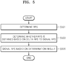
- FIG. 5 is a flowchart illustrating a method of signaling an RPS according to an embodiment of the present invention.
- the picture encoding apparatus 100 may determine an RPS to be used in predictive decoding of a current picture in operation S501. That is, the picture encoding apparatus 100 may determine the RPS which is a set of pictures to be referred to in encoding the current picture.
- the picture encoding apparatus 100 may determine the RPS by referring to an index of one of RPSs defined in an SPS or may additionally define an RPS in a slice header in addition to the RPS defined in the SPS.
- the RPS may be defined by first and second signaling methods that will be described later.
- the picture encoding apparatus 100 may determine whether the RPS is obtained based on a delta RPS in operation S503.
- the picture encoding apparatus 100 may signal the RPS based on a result of the determination of operation S503, in operation S505.
- FIG. 6 is a flowchart illustrating a method of signaling an RPS according to an embodiment of the present invention.
- the picture encoding apparatus 100 may signal an RPS to be used in predictive encoding of a current picture based on a delta RPS, in operation S601.
- the picture encoding apparatus 100 may determine whether the RPS is obtained based on a difference value between POC values of a current picture and a previous picture in order to signal the RPS to be used in predictive decoding of the current picture according to the first method of signaling the RPS to be used in predictive decoding of the current picture, or whether the RPS is obtained based on the delta RPS of the RPS and an index of a reference RPS that may be referred to in determining the RPS in order to signal the RPS to be used in predictive decoding of the current picture according to the second method of signaling the RPS to be used in predictive decoding of the current picture, in operation S603.
- the reference RPS may be one of RPSs pre-defined in an SPS and may be identified as an index of the reference RPS.
- the picture encoding apparatus 100 may determine one of the two signaling methods, which has better encoding efficiency. For example, the picture encoding apparatus 100 may determine the method of signaling the RPS based on a rate distortion cost.
- the RPS is signaled by the first signaling method according to which the RPS is obtained based on the difference value between the POC values of the current picture and the previous picture in operation S605
- a flag having a value of 1 may be added to a predetermined domain of a bit stream in operation S607.
- the RPS to be used in predictive decoding of the current picture may be signaled.
- a flag having a value of 0 may be added to a predetermined domain of the bit stream in operation S609.
- the picture decoding apparatus 200 needs the delta RPS of the current picture and the index of the reference RPS in order to obtain the RPS to be used in predictive decoding of the current picture by an inter-RPS method, and thus, the delta RPS of the current picture that is encoded and the index of the reference RPS need to be added to the bit stream.
- the picture decoding apparatus 100 may determine the index of the reference RPS to be referred to in obtaining the RPS to be used in predictive decoding of the current picture in operation S611.
- the picture decoding apparatus 100 may determine the index of the reference RPS based on encoding efficiency.
- the reference RPS is pre-defined in the SPS and may be identified as an index of each RPS.
- the picture encoding apparatus 100 may obtain the delta RPS by using the index of the reference RPS determined in operation S611, in operation S613.
- the picture encoding apparatus 100 may obtain the reference RPS defined in the SPS by using the index of the reference RPS and may obtain the delta RPS by obtaining a difference between the obtained reference RPS and the RPS to be used in predictive decoding of the current picture.
- a value indicating a reference picture of the reference RPS to which the delta RPS is applied may be defined in operation S613.
- the determined RPS may have the same value as the RPS of ⁇ -2, 0, 2 ⁇ only when the delta RPS is not applied to a POC value of a fourth reference picture when applying the delta RPS to the reference RPS.
- ⁇ 1, 1, 1, 0 ⁇ in which a fourth value for the fourth reference picture is 0 may be defined as a value indicating the reference picture to which the delta RPS is applied.
- the value indicating the reference picture to which the delta RPS is applied may be defined and signaled by the first signaling method as well as the second signaling method.
- the picture encoding apparatus 100 may signal the RPS to be used in prediction decoding of the current picture by encoding the index of the reference RPS and the delta RPS to add to the predetermined domain of the bit stream.
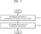
- FIG. 7 is a flowchart illustrating a method of determining an RPS according to an embodiment of the present invention.
- the picture decoding apparatus 200 may determine whether to determine the RPS based on a delta RPS, in order to determine an RPS to be used in predictive decoding of a current picture, in operation S701.
- the picture decoding apparatus 200 may determine the RPS based on a result of the determination of operation S701.
- FIG. 8 is a flowchart illustrating a method of determining an RPS according to an embodiment of the present invention.
- the picture decoding apparatus 200 may obtain a flag indicating whether a first signaling method or a second signaling method is used to determine the RPS to be used in predictive decoding of the current picture, in operation S801.
- the picture decoding apparatus 200 may determine the RPS to be used in predictive decoding of the current picture by using the first signaling method.
- the picture decoding apparatus 200 may obtain POC values of the current picture and a previous picture according to the first signaling method, in operation S805.
- the picture decoding apparatus 200 may obtain the delta RPS of the current picture by using the obtained POC value in operation S807. That is, the picture decoding apparatus 200 may determine a difference value between the POC value of the current picture and the POC value of the previous picture as the delta RPS of the RPS to be used in predictive decoding of the current picture.
- the picture decoding apparatus 200 may obtain an RPS used in predictive decoding of the previous picture, where the RPS is capable of being used as a reference RPS to obtain the RPS, in operation S809.
- the picture decoding apparatus 200 may obtain the RPS by using the delta RPS and the RPS used in predictive decoding of the previous picture, in operation S811. That is, the picture decoding apparatus 200 may obtain the RPS by adding the delta RPS to POC values of reference pictures included in the RPS used in predictive decoding of the previous picture.
- the RPS may be obtained by further using a value indicating the reference picture to which the delta RPS is applied.
- the picture decoding apparatus 200 may determine the RPS to be used in predictive decoding of the current picture by using the second signaling method.
- the picture decoding apparatus 200 may obtain an index of the reference RPS and the delta RPS from a predetermined domain of a bit stream, in operation S813.
- the picture decoding apparatus 200 may obtain the reference RPS by using the index of the reference RPS obtained in operation S813, in operation S815.
- the reference RPS may be a value pre-defined in an SPS, which may be identified as an index.
- the picture decoding apparatus 200 may determine the RPS to be used in predictive decoding of the current picture based on the reference RPS and the delta RPS in operation S817. That is, the picture decoding apparatus 200 may obtain the RPS to be used in predictive decoding of the current picture by adding the delta RPS to POC values of reference pictures of the reference RPS.
- the RPS to be used in predictive decoding of the current picture may be determined based on a value indicating the reference picture of the reference RPS to which the delta RPS may be applied.
- FIG. 9 is a view of an example of an SPS according to an embodiment of the present invention.
- num_short_term_ref_pic_sets (1) may be defined in the SPS as the number of a short term RPS
- short_term_ref_pic_set (i) (3) may be defined in the SPS as much as a value of num_short_term_ref_pic_sets (1).
- an RPS which is a set of reference pictures that are used in predictive decoding of a picture may be defined in the SPS, and each RPS may be identified as an index.
- FIG. 10 is a view of an example of a slice header according to an embodiment of the present invention.
- the short term RPS when the short term RPS is defined in the slice header, 0 may be added to a value of short_term_ref_pic_set_flag (5).
- the short term RPS may be defined in short_term_ref_pic_set (num_short_term_ref_pic_sets) (7) of the slice header.
- the RPS defined in the slice header may be a value other than the RPS defined in the SPS.
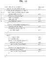
- FIG. 11 is a view of an example of a short term RPS according to an embodiment of the present invention.
- the short term RPS that may be defined in the slice header illustrated in FIG. 10 may be defined in short_term_ref_pic_set (idx).
- a value of inter_ref_pic_set_prediction_flag (9) may be determined based on whether or not the RPS is defined by an inter RPS method.
- inter_ref_pic_set_prediction_flag 1 in if(inter_ref_pic_set_prediction_flag) (11), idx is num_short_term_ref_pic_sets (13), that is, in the case where an index of the RPS is the same as the number of the short RPSs defined in the SPS, a value of derived_delta_rps_flag (15) may be determined.
- the index of the short term RPS defined in the SPS may have a value in a range of 0 to num_short_term_ref_pic_sets-1.
- the case where the index of the RPS is the same as the number of the short term RPSs defined in the SPS is the case where an RPS which is not defined in the SPS is defined in the slice header. That is, the value of derived_delta_rps_flag (15) may be determined in the case where the RPS which is not defined in the SPS is defined in the slice header.
- the value of derived_delta_rps_flag (15) may correspond to the flag that may be obtained by being added to the bit stream according to an exemplary embodiment. Also, the RPS may be signaled based on the value of derived_delta_rps_flag (15).
- the video decoding apparatus 200 may obtain the RPS to be used in predictive decoding of the current picture by using the delta RPS and the index of the reference RPS.
- delta_delta_rps_flag 15
- the delta RPS and the index of the reference RPS may be obtained from delta_idx_minus1 (19), delta_rps_sign (21), and abs_delta_rps_minus1 (23) by Equations 1 and 2 below.
- DeltaRPS 1 ⁇ 2 ⁇ delta _ rps _ sign ⁇ abs _ delta _ rps _ minus 1 + 1
- RIdx idx ⁇ delta _ idx _ minus 1 + 1
- Equations 1 and 2 DeltaRPS denotes the delta RPS and Rldx denotes the index of the reference RPS.
- delta_rps_sign (21) may have a value of 0 or 1, and each value may denote a negative number or a positive number.
- abs_delta_rps_minus1 (23) is a value in which 1 is subtracted from the delta RPS.
- idx denotes an index of the short term RPS defined in the slice header
- delta_idx_minus1 (19) is a delta index value, which is a value obtained by subtracting 1 from a difference value between the RPS and the index of the reference RPS.
- FIGS. 12A and 12B are views of an example of an RPS of pictures according to an exemplary embodiment.
- FIG. 12A illustrates a frame decoded by a random access in which a decoding order and a POC are not the same
- FIG. 12B illustrates a frame decoded by a low delay in which the decoding order and the POC are the same.
- FIGS. 12A and 12B the POC 25 and 31, reference pictures 27 and 33, and delta RPSs 29 and 35 are indicated for each frame. Frame numbers are in accordance with the decoding order.
- the delta RPSs 29 and 35 are each a difference value between POC values of reference pictures included in a reference RPS and reference pictures included in an RPS to be used in predictive decoding of a current picture.
- the POC values of the reference pictures are on the basis of the current picture of 0.
- the reference RPS for each frame illustrated in FIG. 12A is an RPS used in predictive decoding of a frame previously decoded.
- the RPS used in predictive decoding of a previous picture and the RPS used in predictive decoding of the current picture has a difference that is the same as the delta RPS 29.
- the RPS of frame 4 is ⁇ -1, 1, 3, 7 ⁇ and the RPS of frame 5 is ⁇ -1, -3, 1, 5 ⁇ in FIG. 12A .
- the delta RPS of frame 5 is -2.
- the case where the delta RPS is added to the POC value of the RPS may be restricted by a value of reference ides 30. That is, the RPS to be used in predictive decoding of the current picture may be obtained by adding the delta RPS only to the POC value in which the value of the reference ides 30 is 1.
- the value of the reference ides 30 and 36 may correspond to a value indicating a reference picture of the RPS to which the delta RPS may be applied.
- the video decoding apparatus 200 may obtain the delta RPS of the RPS to be used in predictive decoding of the current picture by using a POC difference value between the picture previously decoded and the current picture, without the need of the delta RPS being explicitly encoded and transferred.
- the video decoding apparatus 200 may obtain the delta RPS by using the POC difference value between the current picture and the previous picture, without the need of the delta RPS being explicitly encoded and transferred via the video encoding apparatus 100, in order to signal the delta RPS to obtain the RPS to be used in predictive decoding of the current picture. Therefore, the number of bits encoded in the video encoding apparatus 100 may be reduced.
- the invention can also be embodied as computer readable codes on a computer readable recording medium.
- the computer readable recording medium is any data storage device that can store data which can be thereafter read by a computer system. Examples of the computer readable recording medium include read-only memory (ROM), random-access memory (RAM), CD-ROMs, magnetic tapes, floppy disks, optical data storage devices, etc.
Description
- This application claims the benefit of
U.S. Provisional Application No. 61/624,468, filed on April 16, 2012 - One or more embodiments of the present invention relate to video decoding and encoding methods and video encoding apparatus, for example methods and apparatus that involve determining a reference picture set (RPS) which is a set of reference pictures that are used in predictive decoding of a current picture.
- Recently, with the development of digital display technology and the advent of high-quality digital televisions (TVs), a new codec for processing a large amount of video data has been proposed. Information of reference pictures which are used in predictive decoding of a current picture can be encoded and transferred to a decoding portion. The decoding portion can perform predictive decoding of the current picture by using the transferred information of the reference pictures.
- The standards proposal documents TAN T K ET AL: "AHG21 : Inter reference picture set prediction syntax and semantics", 7. JCT-VC MEETING; M98. MPEG MEETING; 21-11-2011 - 30-11-2011; GENEVA; (JOINT COLLABORATIVE TEAM ON VIDEO CODING OF ISO/IEC JTC1/ SC29/WG11 AND ITU-T SG.16); URL: HTTP://WFTP3.ITU.INT/AV-ARCH/JCTV-SITE/, no JCTVC-G198, 8 November 2011 describes a proposal to reduce the amount of bits necessary for signaling the reference picture set by predicting the delta picture order count (ΔPOC) values using the ΔPOC values from a reference picture set already present in the picture parameter set (PPS). The number of additional PPS signaling bits needed for the random access and low delay common conditions are reduced.
- One or more exemplary embodiments include video decoding and encoding methods and video encoding apparatus, that involve determining a reference picture set (RPS) which is a set of reference pictures that are used in predictive decoding of a current picture.
- Additional aspects will be set forth in part in the description which follows and, in part, will be apparent from the description, or may be learned by practice of the presented embodiments.
- The invention is as set out in the appended claims.
- These and/or other aspects will become apparent and more readily appreciated from the following description of the embodiments, taken in conjunction with the accompanying drawings in which:
-
FIGS. 1A and1B are block diagrams of an internal structure of a video encoding apparatus according to an exemplary embodiment; -
FIGS. 2A and 2B are block diagrams of an internal structure of a video decoding apparatus according to an exemplary embodiment; -
FIG. 3 is a block diagram of an internal structure of a picture encoding unit according to an exemplary embodiment; -
FIG. 4 is a block diagram of an internal structure of a picture decoding unit according to an exemplary embodiment; -
FIGS. 5 and6 are flowcharts illustrating a method of signaling a reference picture set (RPS) according to an exemplary embodiment; -
FIGS. 7 and8 are flowcharts illustrating a method of determining an RPS according to an exemplary embodiment; -
FIG. 9 is a view of an example of a sequence parameter set (SPS) according to an exemplary embodiment; -
FIG. 10 is a view of an example of a slice header according to an exemplary embodiment; -
FIG. 11 is a view of an example of a short term RPS according to an exemplary embodiment; and -
FIGS. 12A and12B are views of an example of an RPS of pictures according to an exemplary embodiment. - Hereinafter, the present invention will be described in detail by explaining preferred embodiments of the invention with reference to the attached drawings. Detailed descriptions of related well-known functions or configurations will be omitted so as not to obscure the description of the present invention. Like reference numerals in the drawings denote like elements.
- The terms and words which are used in the present specification and the appended claims should not be limited to their common or dictionary meanings, because an inventor can define the concept of the terms appropriately to describe his/her invention in the best manner. Therefore, they should be construed as having a meaning and concept fit to the technological concept and scope and of the present invention. Therefore, the embodiments and structures described in the drawings of the present specification are just exemplary embodiments of the present invention, and they do not represent the entire technological concept and scope of the present invention. Therefore, it should be understood that there can be many equivalents and modified embodiments that can substitute those described in this specification.
- The principle of the present invention may be applied to an encoding standard based on an arbitrary intra frame and an inter frame. The term "picture" used throughout the present specification is an inclusive term to denote various forms of video image information that may be known in the related art, such as a "frame," a "field," and a "slice."
- A reference picture may be a picture that may be used for inter-prediction of a block in a current picture.
- Generally, an encoding portion may identify reference pictures by using a picture order count (POC) value. The POC value represents a relative order of display of corresponding pictures. For example, a picture having a low POC value may be displayed earlier than a picture having a high POC value. The order of display and an order of decoding of pictures are different. The picture having the low POC value may not be decoded earlier than the picture having the high POC value. Also, the picture having the low POC value may be decoded earlier than the picture having the high POC value.
- According to an exemplary embodiment, a description is made based on a High Efficiency Video Coding (HEVC) standard. However, it is not limited thereto, and may be applied to other video coding technologies. For example, a reference picture set (RPS) is described based on the HEVC standard, but the RPS may be applied to other standards.
- Hereinafter, one or more embodiments of the present invention will be described more fully with reference to the accompanying drawings.
-
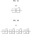
FIGS. 1A and1B are block diagrams of an internal structure of avideo encoding apparatus 100 according to an embodiment of the present invention. - Referring to
FIG. 1A , thevideo encoding apparatus 100 may include anRPS determination unit 101 and a signalingmethod determination unit 102. - An RPS refers to a set of reference pictures which are capable of being used in predictive decoding of a current picture that is to be decoded. The RPS may be defined in a sequence parameter set (SPS) or a slice header. The SPS is header information including information regarding encoding of a sequence, such as a profile, a level, and the like. The SPS may include a plurality of RPSs that are capable of being identified as indexes. The slice header may include an additionally defined RPS in addition to the RPS defined in the SPS. The additionally defined RPS may be used in a picture corresponding to the slice header including the RPS.
- The reference pictures included in the RPS may be indicated as a picture order count (POC) value based on the current picture. That is, when a POC value of the current picture for which the RPS may be used is set to 0, a POC value of the reference picture may be indicated. Although there may be a short term RPS and a long term RPS, the RPS hereinafter may be the short term RPS.
- A method of defining the RPS in the slice header in the
video encoding apparatus 100, that is, a method of signaling an RPS, includes an inter-RPS prediction method. According to the inter-RPS prediction method, thevideo encoding apparatus 100 may signal the RPS in the slice header to obtain an RPS to be used in predictive decoding of the current picture by referring to one of RPSs pre-defined in the SPS. In detail, thevideo encoding apparatus 100 may signal the RPS by adding a delta RPS of the RPS and an index of an RPS that may be referred to in determining the RPS to a bit stream. The RPS may be obtained in a decoding portion by adding the delta RPS, which is a difference between the reference RPS and the RPS to the reference RPS. That is, the RPS may be obtained by adding the delta RPS to each of POC values of reference pictures included in the reference RPS. The reference RPS is a value pre-defined in the SPS and may be identified as an index. - According to an exemplary embodiment, the delta RPS of the RPS that is to be used in predictive decoding of the current picture may be obtained by the fact that the delta RPS of the RPS that is to be used in predictive decoding of the current picture is the same as a difference between a POC value of the current picture and a POC value of a previous picture. Here, the previous picture may refer to a picture previous to the current picture, on a basis of an order of encoding. This is because the reference picture of the current picture should be a reference picture of a picture previously output or a reference picture of a picture previously decoded. Thus, according to the exemplary embodiment, the delta RPS of the RPS may be obtained by a POC difference between the previously decoded picture and the current picture. Accordingly, the
video encoding apparatus 100 may signal the RPS used in predictive decoding of the current picture without adding the delta RPS and the index of the reference RPS to the bit stream. Here, the decoding portion may obtain the delta RPS of the RPS by the difference between the POC values of the current picture and the previous picture and obtain an RPS used in predictive decoding of the previous picture, in order to obtain the RPS to be used in predictive decoding of the current picture from the delta RPS and the RPS used in predictive decoding of the previous picture. - The
video encoding apparatus 100 according to the exemplary embodiment may determine the RPS to be used in predictive decoding of the current picture and may add a flag to the bit stream based on the method of signaling the RPS. Also, thevideo encoding apparatus 100 may encode the current picture by using the determined RPS. - The
RPS determination unit 101 may determine the RPS to be used in predictive decoding of the current picture. The determined RPS may be signaled according to a signaling method determined by the signalingmethod determination unit 102. - The signaling
method determination unit 102 may determine whether to signal the RPS based on the delta RPS and may signal the RPS based on a result of the determination, in order to signal the RPS determined by theRPS determination unit 101. - Referring to
FIG. 1B , thevideo encoding apparatus 100 according to the present embodiment may include anRPS determination unit 110, a signalingmethod determination unit 120, aflag adding unit 130, apicture encoding unit 140 and anoutput unit 150. TheRPS determination unit 110 and the signalingmethod determination unit 120 ofFIG. 1B respectively correspond to theRPS determination unit 101 and the signalingmethod determination unit 102 ofFIG. 1A , and thus, their detailed descriptions will be omitted. TheRPS determination unit 110 may determine the RPS to be used in predictive decoding of the current picture. - The signaling
method determination unit 120 may determine the method of signaling the RPS to be used in predictive decoding of the current picture. The signalingmethod determination unit 120 may determine whether to determine the RPS based on the delta RPS and may determine the method of signaling the RPS based on a result of the determination. According to an exemplary embodiment, there are two methods of signaling the RPS based on the delta RPS. According to the first signaling method, in thevideo encoding apparatus 100, the decoding portion may determine the delta RPS based on POC values of the current picture and the previous picture and may signal the RPS to determine the RPS to be used in predictive decoding of the current picture, based on the determined delta RPS. Also, according to the second signaling method, in thevideo encoding apparatus 100, the decoding portion may signal the RPS to determine the RPS to be used in predictive decoding of the current picture based on the delta RPS and an index of the reference RPS used in predictive decoding of the current picture. The decoding portion may obtain the reference RPS by using the index of the reference RPS transferred from thevideo encoding apparatus 100, and may determine the RPS to be used in predictive decoding of the current picture based on the delta RPS and the reference RPS. - The
flag adding unit 130 may add a flag to a bit stream according to a signaling method determined by the signalingmethod determination unit 120. In detail, theflag adding unit 130 may add flag values, which differ according to the first signaling method and the second signaling method, to the bit stream For example, theflag adding unit 130 may set the flag value to 1 in the case where the RPS to be used in predictive decoding of the current picture is signaled by the first signaling method. Theflag adding unit 130 may set the flag value to 0 in the case where the RPS to be used in predictive decoding of the current picture is signaled by the second signaling method. Thus, the decoding portion may determine the signaling method based on the flag value and determine the RPS to be used in predictive decoding of the current picture based on the determined signaling method. - The
picture encoding unit 140 may encode the current picture by using the RPS determined by theRPS determination unit 110. The encoded picture may be converted to a bit stream to be transferred to avideo decoding apparatus 200 via theoutput unit 150. - The
output unit 150 may output the encoded picture and a bit stream associated with information necessary for decoding the picture. The flag added to the bit stream by theflag adding unit 130 is the information necessary for decoding pictures and may be output by theoutput unit 150 by being added to the bit stream. -
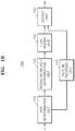
FIGS. 2A and 2B are block diagrams of an internal structure of thevideo decoding apparatus 200 according to an embodiment of the present invention. - Referring to
FIG. 2A , thevideo decoding apparatus 200 may include anRPS determination unit 201. - The
RPS determination unit 201 may determine whether to determine an RPS based on a delta RPS and determine the RPS based on a result of the determination, in order to determine the RPS which is a set of reference pictures that are used in predictive decoding of a current picture. - Referring to
FIG. 2B , thevideo decoding apparatus 200 may include a receivingunit 210, aflag obtaining unit 220, anRPS determination unit 230, and apicture decoding unit 240. TheRPS determination unit 230 ofFIG. 2B corresponds to theRPS determination unit 201 ofFIG. 2A , and thus, its description will not be repeated here. - The receiving
unit 210 may receive a bit stream with respect to an encoded picture to perform parsing. - The
flag obtaining unit 220 may obtain a flag to obtain an RPS in the bit stream for which the parsing is performed. According to a value of the flag, the RPS to be used in predictive decoding of the current picture is determined based on POC values of the current picture and a previous picture, according to the first signaling method. Alternatively, the RPS to be used in predictive decoding of the current picture is determined based on the delta RPS and an index of a reference RPS transferred from thevideo encoding apparatus 100, according to the second signaling method. - The
RPS determination unit 230 may determine the RPS to be used in predictive decoding of the current picture according to the flag obtained by theflag obtaining unit 220. According to the first signaling method, theRPS determination unit 230 may determine the delta RPS of the RPS based on a difference value between the POC values of the current picture and the previous picture, and may determine an RPS used in predictive decoding of the previous picture. In addition, theRPS determination unit 230 may add the determined delta RPS to the RPS used in predictive decoding of the previous picture in order to determine the RPS to be used in predictive decoding of the current picture. That is, the RPS may be determined based on a value of the delta RPS added to each of POC values of reference pictures included in the RPS used in predictive decoding of the previous picture. Also, according to the second signaling method, theRPS determination unit 230 may obtain a reference RPS by using an index of the reference RPS transferred from thevideo encoding apparatus 100. Also, theRPS determination unit 230 may obtain the RPS to be used in predictive decoding of the current picture by adding the delta RPS transferred from thevideo encoding apparatus 100 to the reference RPS. That is, the RPS may be determined based on the value of the delta RPS added to each of the POC values of the reference pictures included in the reference RPS. - The
picture decoding unit 240 may decode a picture by using the RPS determined by theRPS determination unit 230. -
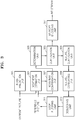
FIG. 3 is a block diagram of an internal structure of a picture encoding unit 300 according to embodiment of the present invention. - Referring to
FIG. 3 , the picture encoding unit 300 may include amovement estimation unit 301, amovement compensation unit 302, anintra-prediction unit 303, a convertingunit 305, aquantization unit 306, anentropy encoding unit 307, areverse quantization unit 308, areverse converting unit 309, adeblocking unit 310, and aloop filtering unit 311. The picture encoding unit 300 ofFIG. 3 may correspond to thepicture encoding unit 140 ofFIG. 1 . - The
movement estimation unit 301 may estimate the movement of the current picture by using reference pictures included in an RPS with respect to a current picture which is a picture currently input from the outside among pictures forming a video. - The
movement compensation unit 302 may generate a predictive picture of the current picture by using the reference pictures included in the RPS with respect to the current picture. In more detail, themovement compensation unit 302 may generate the predictive picture of the current picture by using the movement of the current picture, which is estimated by themovement estimation unit 301. - The
intra-prediction unit 303 may predict each of intra mode blocks among blocks forming the current picture to generate the predictive picture of the current picture. - The converting
unit 305 may convert a residual picture, which is calculated by subtracting the predictive picture from the current picture, from a spatial domain to a frequency domain. For example, the convertingunit 305 may convert the residual picture from the spatial domain to the frequency domain by using an integer transform of the discrete Hadamard transform (DHT) and discrete cosine transform (DCT). - The
quantization unit 306 may quantize frequency coefficients of the residual picture converted by the convertingunit 305. - The
entropy encoding unit 307 may generate a bit stream by entropy-encoding results of quantization by thequantization unit 306. In particular, theentropy encoding unit 307 may entropy encode information for video decoding, for example, RPS information used in inter-prediction, movement vector information, location information of neighboring blocks used in intra-prediction, in addition to the results of quantization by thequantization unit 306. - The
reverse quantization unit 308 may reverse-quantize the results of quantization by thequantization unit 306. - The
reverse converting unit 309 may convert results of quantization by thereverse quantization unit 308. That is, thereverse converting unit 309 may convert conversion coefficient values from a frequency domain to a spatial domain to restore the residual picture of the current picture and the predictive picture. - The
deblocking unit 310 and theloop filtering unit 311 may adaptively perform filtering for the picture restored by thereverse quantization unit 308. -
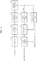
FIG. 4 is a block diagram of an internal structure of a picture decoding unit according to an embodiment of the present invention. - Referring to
FIG. 4 , the picture decoding unit 400 may include aparsing unit 401, anentropy decoding unit 403, areverse quantization unit 405, areverse converting unit 407, anintra-prediction unit 409, amovement compensation unit 415, adeblocking unit 411, and aloop filtering unit 413. The picture decoding unit 400 ofFIG. 4 may correspond to thepicture decoding unit 240 ofFIG. 2 . - The
parsing unit 401 may perform parsing with respect to data of an encoded picture which is to be decoded and with respect to information related to decoding, which is necessary for encoding, from a bit stream. - The
entropy decoding unit 403 may restore information for video decoding by entropy decoding the bit stream. - The
reverse quantization unit 405 may restore conversion coefficient values by reverse quantizing values restored by theentropy decoding unit 403. - The
reverse converting unit 407 may restore a residual picture of a current picture and a predictive picture by converting the conversion coefficient values restored by the reverse quantization unit 402 from a frequency domain to a spatial domain. - The
intra-prediction unit 409 may generate the predictive picture of the current picture by predicting a value of a block of the current picture from a value of a restored block located neighboring a block of the current picture. The restored picture may be generated by adding the residual picture to the predictive picture. - The
movement compensation unit 415 may generate the predictive picture of the current picture from reference pictures included in an RPS to be used in predictive decoding of the current picture. The restored picture may be generated by adding the residual picture to the predictive picture. - The
deblocking unit 411 and theloop filtering unit 413 may adaptively perform filtering for the restored picture. -
FIG. 5 is a flowchart illustrating a method of signaling an RPS according to an embodiment of the present invention. - Referring to
FIG. 5 , thepicture encoding apparatus 100 according to an exemplary embodiment may determine an RPS to be used in predictive decoding of a current picture in operation S501. That is, thepicture encoding apparatus 100 may determine the RPS which is a set of pictures to be referred to in encoding the current picture. Thepicture encoding apparatus 100 may determine the RPS by referring to an index of one of RPSs defined in an SPS or may additionally define an RPS in a slice header in addition to the RPS defined in the SPS. According to an exemplary embodiment, in the case where an additional RPS is defined in the slice header in addition to the RPS defined in the SPS, the RPS may be defined by first and second signaling methods that will be described later. - The
picture encoding apparatus 100 may determine whether the RPS is obtained based on a delta RPS in operation S503. - The
picture encoding apparatus 100 may signal the RPS based on a result of the determination of operation S503, in operation S505. -
FIG. 6 is a flowchart illustrating a method of signaling an RPS according to an embodiment of the present invention. - Referring to
FIG. 6 , thepicture encoding apparatus 100 may signal an RPS to be used in predictive encoding of a current picture based on a delta RPS, in operation S601. - In the case where the
picture encoding apparatus 100 signals the RPS based on the delta RPS, thepicture encoding apparatus 100 may determine whether the RPS is obtained based on a difference value between POC values of a current picture and a previous picture in order to signal the RPS to be used in predictive decoding of the current picture according to the first method of signaling the RPS to be used in predictive decoding of the current picture, or whether the RPS is obtained based on the delta RPS of the RPS and an index of a reference RPS that may be referred to in determining the RPS in order to signal the RPS to be used in predictive decoding of the current picture according to the second method of signaling the RPS to be used in predictive decoding of the current picture, in operation S603. Here, the reference RPS may be one of RPSs pre-defined in an SPS and may be identified as an index of the reference RPS. Thepicture encoding apparatus 100 may determine one of the two signaling methods, which has better encoding efficiency. For example, thepicture encoding apparatus 100 may determine the method of signaling the RPS based on a rate distortion cost. When the RPS is signaled by the first signaling method according to which the RPS is obtained based on the difference value between the POC values of the current picture and the previous picture in operation S605, a flag having a value of 1 may be added to a predetermined domain of a bit stream in operation S607. By this, the RPS to be used in predictive decoding of the current picture may be signaled. - When the RPS to be used in predictive decoding of the current picture is signaled by the second signaling method according to which the delta RPS and the index of the reference RPS are signaled in operation S605, a flag having a value of 0 may be added to a predetermined domain of the bit stream in operation S609.
- According to the second signaling method, the
picture decoding apparatus 200 needs the delta RPS of the current picture and the index of the reference RPS in order to obtain the RPS to be used in predictive decoding of the current picture by an inter-RPS method, and thus, the delta RPS of the current picture that is encoded and the index of the reference RPS need to be added to the bit stream. - The
picture decoding apparatus 100 may determine the index of the reference RPS to be referred to in obtaining the RPS to be used in predictive decoding of the current picture in operation S611. Here, thepicture decoding apparatus 100 may determine the index of the reference RPS based on encoding efficiency. The reference RPS is pre-defined in the SPS and may be identified as an index of each RPS. - The
picture encoding apparatus 100 may obtain the delta RPS by using the index of the reference RPS determined in operation S611, in operation S613. Thepicture encoding apparatus 100 may obtain the reference RPS defined in the SPS by using the index of the reference RPS and may obtain the delta RPS by obtaining a difference between the obtained reference RPS and the RPS to be used in predictive decoding of the current picture. - In addition, a value indicating a reference picture of the reference RPS to which the delta RPS is applied may be defined in operation S613. For example, when the reference RPS is {-1, 1, 3, 5}, the RPS to be used in predictive decoding of the current picture and to be signaled is {-2, 0, 2}, and a value of the delta RPS is -1, the determined RPS may have the same value as the RPS of {-2, 0, 2} only when the delta RPS is not applied to a POC value of a fourth reference picture when applying the delta RPS to the reference RPS. Thus, {1, 1, 1, 0} in which a fourth value for the fourth reference picture is 0 may be defined as a value indicating the reference picture to which the delta RPS is applied. The value indicating the reference picture to which the delta RPS is applied may be defined and signaled by the first signaling method as well as the second signaling method.
- The
picture encoding apparatus 100 may signal the RPS to be used in prediction decoding of the current picture by encoding the index of the reference RPS and the delta RPS to add to the predetermined domain of the bit stream. -
FIG. 7 is a flowchart illustrating a method of determining an RPS according to an embodiment of the present invention. - Referring to
FIG. 7 , thepicture decoding apparatus 200 may determine whether to determine the RPS based on a delta RPS, in order to determine an RPS to be used in predictive decoding of a current picture, in operation S701. - In operation S703, the
picture decoding apparatus 200 may determine the RPS based on a result of the determination of operation S701. -
FIG. 8 is a flowchart illustrating a method of determining an RPS according to an embodiment of the present invention. - Referring to
FIG. 8 , when thepicture decoding apparatus 200 determines the RPS based on the delta RPS, thepicture decoding apparatus 200 may obtain a flag indicating whether a first signaling method or a second signaling method is used to determine the RPS to be used in predictive decoding of the current picture, in operation S801. - When the flag is 1 in operation S803, the
picture decoding apparatus 200 may determine the RPS to be used in predictive decoding of the current picture by using the first signaling method. - The
picture decoding apparatus 200 may obtain POC values of the current picture and a previous picture according to the first signaling method, in operation S805. - The
picture decoding apparatus 200 may obtain the delta RPS of the current picture by using the obtained POC value in operation S807. That is, thepicture decoding apparatus 200 may determine a difference value between the POC value of the current picture and the POC value of the previous picture as the delta RPS of the RPS to be used in predictive decoding of the current picture. - The
picture decoding apparatus 200 may obtain an RPS used in predictive decoding of the previous picture, where the RPS is capable of being used as a reference RPS to obtain the RPS, in operation S809. - The
picture decoding apparatus 200 may obtain the RPS by using the delta RPS and the RPS used in predictive decoding of the previous picture, in operation S811. That is, thepicture decoding apparatus 200 may obtain the RPS by adding the delta RPS to POC values of reference pictures included in the RPS used in predictive decoding of the previous picture. Here, the RPS may be obtained by further using a value indicating the reference picture to which the delta RPS is applied. - Meanwhile, when the flag is 0 in operation S803, the
picture decoding apparatus 200 may determine the RPS to be used in predictive decoding of the current picture by using the second signaling method. - The
picture decoding apparatus 200 may obtain an index of the reference RPS and the delta RPS from a predetermined domain of a bit stream, in operation S813. - The
picture decoding apparatus 200 may obtain the reference RPS by using the index of the reference RPS obtained in operation S813, in operation S815. The reference RPS may be a value pre-defined in an SPS, which may be identified as an index. - The
picture decoding apparatus 200 may determine the RPS to be used in predictive decoding of the current picture based on the reference RPS and the delta RPS in operation S817. That is, thepicture decoding apparatus 200 may obtain the RPS to be used in predictive decoding of the current picture by adding the delta RPS to POC values of reference pictures of the reference RPS. Here, the RPS to be used in predictive decoding of the current picture may be determined based on a value indicating the reference picture of the reference RPS to which the delta RPS may be applied. -
FIG. 9 is a view of an example of an SPS according to an embodiment of the present invention. - Referring to
FIG. 9 , num_short_term_ref_pic_sets (1) may be defined in the SPS as the number of a short term RPS, and short_term_ref_pic_set (i) (3) may be defined in the SPS as much as a value of num_short_term_ref_pic_sets (1). As described earlier, an RPS which is a set of reference pictures that are used in predictive decoding of a picture may be defined in the SPS, and each RPS may be identified as an index. -
FIG. 10 is a view of an example of a slice header according to an embodiment of the present invention. - Referring to
FIG. 10 , when the short term RPS is defined in the slice header, 0 may be added to a value of short_term_ref_pic_set_flag (5). When the value of short_term_ref_pic_set_sps_flag (5) is 0, the short term RPS may be defined in short_term_ref_pic_set (num_short_term_ref_pic_sets) (7) of the slice header. The RPS defined in the slice header may be a value other than the RPS defined in the SPS. -
FIG. 11 is a view of an example of a short term RPS according to an embodiment of the present invention. - Referring to
FIG. 11 , the short term RPS that may be defined in the slice header illustrated inFIG. 10 may be defined in short_term_ref_pic_set (idx). - A value of inter_ref_pic_set_prediction_flag (9) may be determined based on whether or not the RPS is defined by an inter RPS method.
- In the case where, if the value of inter_ref_pic_set_prediction_flag is 1 in if(inter_ref_pic_set_prediction_flag) (11), idx is num_short_term_ref_pic_sets (13), that is, in the case where an index of the RPS is the same as the number of the short RPSs defined in the SPS, a value of derived_delta_rps_flag (15) may be determined.
- The index of the short term RPS defined in the SPS may have a value in a range of 0 to num_short_term_ref_pic_sets-1. Thus, the case where the index of the RPS is the same as the number of the short term RPSs defined in the SPS is the case where an RPS which is not defined in the SPS is defined in the slice header. That is, the value of derived_delta_rps_flag (15) may be determined in the case where the RPS which is not defined in the SPS is defined in the slice header.
- The value of derived_delta_rps_flag (15) may correspond to the flag that may be obtained by being added to the bit stream according to an exemplary embodiment. Also, the RPS may be signaled based on the value of derived_delta_rps_flag (15).
- In the case where derived_delta_rps_flag (15) is 0, the
video decoding apparatus 200 may obtain the RPS to be used in predictive decoding of the current picture by using the delta RPS and the index of the reference RPS. - In the case where derived_delta_rps_flag (15) is 1, the delta RPS and the index of the reference RPS may be obtained from delta_idx_minus1 (19), delta_rps_sign (21), and abs_delta_rps_minus1 (23) by
Equations 

- In
Equations - delta_rps_sign (21) may have a value of 0 or 1, and each value may denote a negative number or a positive number. abs_delta_rps_minus1 (23) is a value in which 1 is subtracted from the delta RPS.
- idx denotes an index of the short term RPS defined in the slice header, and delta_idx_minus1 (19) is a delta index value, which is a value obtained by subtracting 1 from a difference value between the RPS and the index of the reference RPS.
-
FIGS. 12A and12B are views of an example of an RPS of pictures according to an exemplary embodiment.FIG. 12A illustrates a frame decoded by a random access in which a decoding order and a POC are not the same, andFIG. 12B illustrates a frame decoded by a low delay in which the decoding order and the POC are the same. - Referring to
FIGS. 12A and12B , thePOC delta RPSs - The
delta RPSs FIG. 12A is an RPS used in predictive decoding of a frame previously decoded. Thus, referring to the reference pictures 27 and 33, the RPS used in predictive decoding of a previous picture and the RPS used in predictive decoding of the current picture has a difference that is the same as thedelta RPS 29. - For example, the RPS of
frame 4 is {-1, 1, 3, 7} and the RPS offrame 5 is {-1, -3, 1, 5} inFIG. 12A . Also, the delta RPS offrame 5 is -2. Thus, the RPS offrame 5 may be obtained by adding the delta RPS to RPS ofFIG. 4 . That is, the RPS offrame 5 may be {-1-2=-3, 1-2=-1, 3-2=1, 7-2=5}. However, the case where the delta RPS is added to the POC value of the RPS may be restricted by a value of reference ides 30. That is, the RPS to be used in predictive decoding of the current picture may be obtained by adding the delta RPS only to the POC value in which the value of thereference ides 30 is 1. The value of thereference ides - Meanwhile, when comparing the
delta RPSs POC delta RPSs video decoding apparatus 200 may obtain the delta RPS of the RPS to be used in predictive decoding of the current picture by using a POC difference value between the picture previously decoded and the current picture, without the need of the delta RPS being explicitly encoded and transferred. - As described above, according to the one or more of the above exemplary embodiments, the
video decoding apparatus 200 may obtain the delta RPS by using the POC difference value between the current picture and the previous picture, without the need of the delta RPS being explicitly encoded and transferred via thevideo encoding apparatus 100, in order to signal the delta RPS to obtain the RPS to be used in predictive decoding of the current picture. Therefore, the number of bits encoded in thevideo encoding apparatus 100 may be reduced. - The invention can also be embodied as computer readable codes on a computer readable recording medium. The computer readable recording medium is any data storage device that can store data which can be thereafter read by a computer system. Examples of the computer readable recording medium include read-only memory (ROM), random-access memory (RAM), CD-ROMs, magnetic tapes, floppy disks, optical data storage devices, etc.
- It should be understood that the exemplary embodiments described herein should be considered in a descriptive sense only and not for purposes of limitation. Descriptions of features or aspects within each embodiment should typically be considered as available for other similar features or aspects in other embodiments.
- While one or more embodiments of the present invention have been described with reference to the figures, it will be understood by those of ordinary skill in the art that various changes in form and details may be made therein without departing from the scope of the present invention as defined by the following claims.
Claims (3)
- A video decoding method comprising:obtaining, from a bitstream, the number of short term reference picture sets included in a part of the bitstream about a sequence parameter set;determining whether a current index of a short term reference picture set is equal to the number of short term reference picture sets included in the part of the bitstream about the sequence parameter set;when the current index of the short term reference picture set is equal to the number of short term reference picture sets, obtaining, from the bitstream, delta index information about a difference between the current index of the short term reference picture set and an index of a reference short term reference picture set, information about a sign of a delta RPS and information about an absolute value of the delta RPS;determining the index of the reference short term reference picture set which indicates the reference short term reference picture set based on the delta index information and the current index of the short term reference picture set;determining the delta RPS based on the information about the sign of the delta RPS and the information about the absolute value of the delta RPS;determining delta picture order count(POC) values between picture order count(POC) values of reference pictures included in a current short term reference picture set and picture order count(POC) value of the current picture by adding each delta POC value between picture order count(POC) value of reference picture in the reference short term reference picture set which is identified by the index of the reference short term reference picture set and the picture order count(POC) value of the current picture to the delta RPS; anddetermining POC values of the reference pictures included in the current short term reference picture set based on the picture order count (POC) value of the current picture and the delta picture order count (POC) values between the picture order count (POC) values of the reference pictures included in the current short term reference picture set and the picture order count (POC) value of the current picture,wherein the current index of the short term reference picture set being equal to the number of short term reference picture sets indicates the short term reference picture set regarding the current index is not defined in the sequence parameter set and is defined in a slice header.
- A method of encoding a video, the method comprising:determining short term reference picture sets available to predict a current picture;generating information regarding the number of short term reference picture sets included in a part of a bitstream about a sequence parameter set;generating delta index information about a difference between a current index of a short term reference picture set and an index of a reference short term reference picture set, and generating information about a sign of a delta RPS and information about an absolute value of the delta RPS,wherein the delta index information, the information about the sign of the delta RPS and the information about the absolute value of the delta RPS are generated and are included in the bitstream to determine, by a video decoding apparatus, an index of a reference short term reference picture set, determine the delta RPS, and determine delta picture order count(POC) values between picture order count (POC) values of reference pictures included in a current short term reference picture set and picture order count (POC) value of the current picture by adding each delta POC value between picture order count(POC) value of reference picture in the reference short term reference picture set and the picture order count (POC) value of the current picture to the delta RPS, and determine POC values of the reference pictures included in the current short term reference picture set based on the picture order count (POC) value of the current picture and the delta picture order count (POC) values between the picture order count (POC) values of the reference pictures included in the current short term reference picture set and the picture order count (POC) value of the current picture, when the current index of the short term reference picture set is equal to the number of the short term reference picture sets in the part of the bitstream about the sequence parameter set;generating the bitstream including the information regarding the number of short term reference picture sets in the part of the bitstream about the sequence parameter set, the delta index information, the information about the sign of the delta RPS and the information about the absolute value of the delta RPS,wherein the current index of the short term reference picture set being equal to the number of short term reference picture sets indicates the short term reference picture set regarding the current index is not defined in the sequence parameter set and is defined in a slice header.
- An apparatus of encoding a video, the apparatus comprising:at least one processor configured to determine short term reference picture sets available to predict a current picture, generate information regarding the number of short term reference picture sets included in a part of a bitstream about a sequence parameter set, generate delta index information about a difference between a current index of a short term reference picture set and an index of a reference short term reference picture set, generate information about a sign of a delta RPS and information about an absolute value of the delta RPS, wherein the delta index information, the information about the sign of the delta RPS and the information about the absolute value of the delta RPS are generated and included in the bitstream to determine, by a video decoding apparatus, an index of a reference short term reference picture set, determine the delta RPS, and determine delta picture order count(POC) values between picture order count (POC) values of reference pictures included in a current short term reference picture set and picture order count (POC) value of the current picture by adding each delta POC value between picture order count(POC) value of reference picture in the reference short term reference picture set and the picture order count (POC) value of the current picture to the delta RPS, and determine POC values of the reference pictures included in the current short term reference picture set based on the picture order count (POC) value of the current picture and the delta picture order count (POC) values between the picture order count (POC) values of the reference pictures included in the current short term reference picture set and the picture order count (POC) value of the current picture, when the current index of the short term reference picture set is equal to the number of the short term reference picture sets in the part of the bitstream about the sequence parameter set, generate the bitstream including the information regarding the number of short term reference picture sets in the part of the bitstream about the sequence parameter set the delta index information, the information about the sign of the delta RPS and the information about the absolute value of the delta RPS,wherein the current index of the short term reference picture set being equal to the number of short term reference picture sets indicates the short term reference picture set regarding the current index is not defined in the sequence parameter set and is defined in a slice header.
Priority Applications (2)
| Application Number | Priority Date | Filing Date | Title |
|---|---|---|---|
| EP20211570.5A EP3806473A1 (en) | 2012-04-16 | 2013-04-16 | Method and apparatus for determining reference picture set of image |
| PL19194263T PL3595315T3 (en) | 2012-04-16 | 2013-04-16 | Method and apparatus for determining reference picture set of image |
Applications Claiming Priority (3)
| Application Number | Priority Date | Filing Date | Title |
|---|---|---|---|
| US201261624468P | 2012-04-16 | 2012-04-16 | |
| PCT/KR2013/003181 WO2013157814A1 (en) | 2012-04-16 | 2013-04-16 | Method and apparatus for determining reference picture set of image |
| EP13778457.5A EP2830313B1 (en) | 2012-04-16 | 2013-04-16 | Method and apparatus for determining reference picture set of image |
Related Parent Applications (2)
| Application Number | Title | Priority Date | Filing Date |
|---|---|---|---|
| EP13778457.5A Division EP2830313B1 (en) | 2012-04-16 | 2013-04-16 | Method and apparatus for determining reference picture set of image |
| EP13778457.5A Division-Into EP2830313B1 (en) | 2012-04-16 | 2013-04-16 | Method and apparatus for determining reference picture set of image |
Related Child Applications (2)
| Application Number | Title | Priority Date | Filing Date |
|---|---|---|---|
| EP20211570.5A Division EP3806473A1 (en) | 2012-04-16 | 2013-04-16 | Method and apparatus for determining reference picture set of image |
| EP20211570.5A Division-Into EP3806473A1 (en) | 2012-04-16 | 2013-04-16 | Method and apparatus for determining reference picture set of image |
Publications (2)
| Publication Number | Publication Date |
|---|---|
| EP3595315A1 EP3595315A1 (en) | 2020-01-15 |
| EP3595315B1 true EP3595315B1 (en) | 2021-01-13 |
Family
ID=49383703
Family Applications (3)
| Application Number | Title | Priority Date | Filing Date |
|---|---|---|---|
| EP20211570.5A Pending EP3806473A1 (en) | 2012-04-16 | 2013-04-16 | Method and apparatus for determining reference picture set of image |
| EP13778457.5A Active EP2830313B1 (en) | 2012-04-16 | 2013-04-16 | Method and apparatus for determining reference picture set of image |
| EP19194263.0A Active EP3595315B1 (en) | 2012-04-16 | 2013-04-16 | Method and apparatus for determining reference picture set of image |
Family Applications Before (2)
| Application Number | Title | Priority Date | Filing Date |
|---|---|---|---|
| EP20211570.5A Pending EP3806473A1 (en) | 2012-04-16 | 2013-04-16 | Method and apparatus for determining reference picture set of image |
| EP13778457.5A Active EP2830313B1 (en) | 2012-04-16 | 2013-04-16 | Method and apparatus for determining reference picture set of image |
Country Status (18)
| Country | Link |
|---|---|
| US (6) | US10171811B2 (en) |
| EP (3) | EP3806473A1 (en) |
| JP (2) | JP6030749B2 (en) |
| KR (3) | KR101830885B1 (en) |
| CN (5) | CN108833926B (en) |
| CA (1) | CA2870680C (en) |
| DK (1) | DK2830313T3 (en) |
| ES (2) | ES2850223T3 (en) |
| HU (1) | HUE052896T2 (en) |
| IN (1) | IN2014MN02262A (en) |
| MX (1) | MX345247B (en) |
| MY (3) | MY175301A (en) |
| PH (5) | PH12014502315A1 (en) |
| PL (2) | PL2830313T3 (en) |
| RU (4) | RU2593264C2 (en) |
| SG (2) | SG10201701147XA (en) |
| WO (1) | WO2013157814A1 (en) |
| ZA (1) | ZA201408390B (en) |
Families Citing this family (7)
| Publication number | Priority date | Publication date | Assignee | Title |
|---|---|---|---|---|
| SG10201701147XA (en) | 2012-04-16 | 2017-03-30 | Samsung Electronics Co Ltd | Method and apparatus for determining reference picture set of image |
| AU2013281243C1 (en) | 2012-06-29 | 2016-01-21 | Telefonaktiebolaget Lm Ericsson (Publ) | Encoding and decoding video sequences comprising reference picture sets |
| MX342497B (en) * | 2012-06-29 | 2016-10-03 | Sony Corp | Coding device, and coding method. |
| US10432928B2 (en) | 2014-03-21 | 2019-10-01 | Qualcomm Incorporated | Using a current picture as a reference for video coding |
| FR3046321B1 (en) * | 2015-12-29 | 2018-01-26 | B<>Com | DIGITAL IMAGE ENCODING METHOD, DECODING METHOD, DEVICES, USER TERMINAL, AND ASSOCIATED COMPUTER PROGRAMS |
| BR112021004662A2 (en) * | 2018-09-12 | 2021-06-01 | Huawei Technologies Co., Ltd. | video encoder, video decoder and corresponding methods |
| CN113228519A (en) * | 2018-12-14 | 2021-08-06 | 华为技术有限公司 | Arbitrary and surround block grouping |
Family Cites Families (35)
| Publication number | Priority date | Publication date | Assignee | Title |
|---|---|---|---|---|
| JP3263807B2 (en) | 1996-09-09 | 2002-03-11 | ソニー株式会社 | Image encoding apparatus and image encoding method |
| FI120125B (en) | 2000-08-21 | 2009-06-30 | Nokia Corp | Image Coding |
| KR100491530B1 (en) * | 2002-05-03 | 2005-05-27 | 엘지전자 주식회사 | Method of determining motion vector |
| KR100865034B1 (en) | 2002-07-18 | 2008-10-23 | 엘지전자 주식회사 | Method for predicting motion vector |
| CA2500301C (en) * | 2002-10-01 | 2013-05-14 | Thomson Licensing S.A. | Implicit weighting of reference pictures in a video decoder |
| CA2473898C (en) * | 2002-11-25 | 2013-02-12 | Matsushita Electric Industrial Co., Ltd. | Moving picture coding method and moving picture decoding method |
| CN1875637A (en) * | 2003-08-26 | 2006-12-06 | 汤姆森特许公司 | Method and apparatus for minimizing number of reference pictures used for inter-coding |
| KR101094323B1 (en) | 2003-09-17 | 2011-12-19 | 톰슨 라이센싱 | Adaptive reference picture generation |
| US20070199011A1 (en) * | 2006-02-17 | 2007-08-23 | Sony Corporation | System and method for high quality AVC encoding |
| CN101449585A (en) * | 2006-03-30 | 2009-06-03 | Lg电子株式会社 | A method and apparatus for decoding/encoding a video signal |
| CN101611633B (en) | 2006-07-06 | 2012-10-03 | 汤姆逊许可证公司 | Method and apparatus for decoupling frame number and/or picture order count (poc) for multi-view video encoding and decoding |
| WO2008023967A1 (en) | 2006-08-25 | 2008-02-28 | Lg Electronics Inc | A method and apparatus for decoding/encoding a video signal |
| US20080165860A1 (en) * | 2006-08-31 | 2008-07-10 | Zohair Sahraoui | H.264 Data processing |
| KR100941608B1 (en) | 2006-10-17 | 2010-02-11 | 경희대학교 산학협력단 | Method for encoding and decoding a multi-view video and apparatus therefor |
| US8121195B2 (en) | 2006-11-30 | 2012-02-21 | Lsi Corporation | Memory reduced H264/MPEG-4 AVC codec |
| JP5023739B2 (en) | 2007-02-28 | 2012-09-12 | ソニー株式会社 | Image information encoding apparatus and encoding method |
| BRPI0809210A2 (en) | 2007-04-04 | 2014-09-02 | Thomson Licensing | REFERENCE IMAGE LIST MANAGEMENT |
| CN101291434A (en) * | 2007-04-17 | 2008-10-22 | 华为技术有限公司 | Encoding/decoding method and device for multi-video |
| CN101119493B (en) * | 2007-08-30 | 2010-12-01 | 威盛电子股份有限公司 | Coding method and device for block type digital coding image |
| JP2009260736A (en) * | 2008-03-24 | 2009-11-05 | Fujitsu Ltd | Encoding apparatus, decoding apparatus, moving image processing method, moving image processing system, encoding program, and decoding program |
| JP5259315B2 (en) * | 2008-09-16 | 2013-08-07 | オリンパスイメージング株式会社 | Image search device, digital camera, image search method, and image search program |
| KR100943571B1 (en) | 2009-03-04 | 2010-02-23 | 엘지전자 주식회사 | Method for predicting motion vector |
| JP2011082683A (en) | 2009-10-05 | 2011-04-21 | Sony Corp | Image processing apparatus, image processing method, and program |
| KR101456499B1 (en) * | 2010-07-09 | 2014-11-03 | 삼성전자주식회사 | Method and apparatus for encoding and decoding motion vector |
| US9300970B2 (en) | 2010-07-09 | 2016-03-29 | Samsung Electronics Co., Ltd. | Methods and apparatuses for encoding and decoding motion vector |
| JP2012023651A (en) | 2010-07-16 | 2012-02-02 | Sony Corp | Image processing device and image processing method |
| CN102025992B (en) | 2010-11-23 | 2012-11-21 | 浙江大学 | Reference-image management method for interframe predicting process in H.264 video decoding system |
| EP2687012A1 (en) | 2011-06-30 | 2014-01-22 | Telefonaktiebolaget L M Ericsson (PUBL) | Absolute or explicit reference picture signaling |
| EP3902258A1 (en) | 2011-06-30 | 2021-10-27 | Telefonaktiebolaget LM Ericsson (publ) | Reference picture signaling |
| JP5082005B2 (en) * | 2011-09-26 | 2012-11-28 | 株式会社日本ビジネスエンジニアリング | Imaging data processing device |
| US8693793B2 (en) * | 2012-01-19 | 2014-04-08 | Sharp Laboratories Of America, Inc. | Reducing reference picture set signal overhead on an electronic device |
| US8867852B2 (en) * | 2012-01-19 | 2014-10-21 | Sharp Kabushiki Kaisha | Decoding a picture based on a reference picture set on an electronic device |
| KR101652928B1 (en) * | 2012-01-31 | 2016-09-01 | 브이아이디 스케일, 인크. | Reference picture set(rps) signaling for scalable high efficiency video coding(hevc) |
| US9532046B2 (en) * | 2012-04-16 | 2016-12-27 | Qualcomm Incorporated | Reference picture set prediction for video coding |
| SG10201701147XA (en) | 2012-04-16 | 2017-03-30 | Samsung Electronics Co Ltd | Method and apparatus for determining reference picture set of image |
-
2013
- 2013-04-16 SG SG10201701147XA patent/SG10201701147XA/en unknown
- 2013-04-16 ES ES19194263T patent/ES2850223T3/en active Active
- 2013-04-16 US US14/394,820 patent/US10171811B2/en active Active
- 2013-04-16 EP EP20211570.5A patent/EP3806473A1/en active Pending
- 2013-04-16 CN CN201810708748.5A patent/CN108833926B/en active Active
- 2013-04-16 RU RU2014145867/07A patent/RU2593264C2/en active
- 2013-04-16 IN IN2262MUN2014 patent/IN2014MN02262A/en unknown
- 2013-04-16 CA CA2870680A patent/CA2870680C/en active Active
- 2013-04-16 ES ES13778457T patent/ES2754023T3/en active Active
- 2013-04-16 MY MYPI2014703066A patent/MY175301A/en unknown
- 2013-04-16 PL PL13778457T patent/PL2830313T3/en unknown
- 2013-04-16 CN CN201380031852.0A patent/CN104380750B/en active Active
- 2013-04-16 JP JP2015506888A patent/JP6030749B2/en active Active
- 2013-04-16 CN CN201810709489.8A patent/CN108495137B/en active Active
- 2013-04-16 SG SG11201406675WA patent/SG11201406675WA/en unknown
- 2013-04-16 EP EP13778457.5A patent/EP2830313B1/en active Active
- 2013-04-16 DK DK13778457T patent/DK2830313T3/en active
- 2013-04-16 WO PCT/KR2013/003181 patent/WO2013157814A1/en active Application Filing
- 2013-04-16 EP EP19194263.0A patent/EP3595315B1/en active Active
- 2013-04-16 CN CN201810709026.1A patent/CN108989821B/en active Active
- 2013-04-16 CN CN201810710485.1A patent/CN108881925B/en active Active
- 2013-04-16 MY MYPI2018700502A patent/MY198312A/en unknown
- 2013-04-16 RU RU2016125239A patent/RU2627302C1/en active
- 2013-04-16 MX MX2014012517A patent/MX345247B/en active IP Right Grant
- 2013-04-16 PL PL19194263T patent/PL3595315T3/en unknown
- 2013-04-16 MY MYPI2018700503A patent/MY198315A/en unknown
- 2013-04-16 HU HUE19194263A patent/HUE052896T2/en unknown
- 2013-04-16 KR KR1020130041841A patent/KR101830885B1/en active IP Right Grant
-
2014
- 2014-10-16 PH PH12014502315A patent/PH12014502315A1/en unknown
- 2014-11-13 ZA ZA2014/08390A patent/ZA201408390B/en unknown
-
2016
- 2016-10-20 JP JP2016206194A patent/JP6553573B2/en active Active
-
2017
- 2017-06-30 RU RU2017123119A patent/RU2654512C1/en active
- 2017-12-12 PH PH12017502290A patent/PH12017502290A1/en unknown
- 2017-12-12 PH PH12017502289A patent/PH12017502289A1/en unknown
- 2017-12-12 PH PH12017502288A patent/PH12017502288A1/en unknown
- 2017-12-12 PH PH12017502287A patent/PH12017502287A1/en unknown
-
2018
- 2018-02-13 KR KR1020180018074A patent/KR102149510B1/en active IP Right Grant
- 2018-04-18 RU RU2018114251A patent/RU2689327C1/en active
- 2018-12-03 US US16/207,656 patent/US10609378B2/en active Active
-
2020
- 2020-02-24 US US16/799,362 patent/US11006120B2/en active Active
- 2020-08-24 KR KR1020200106450A patent/KR102257997B1/en active IP Right Grant
-
2021
- 2021-04-15 US US17/231,763 patent/US11490091B2/en active Active
-
2022
- 2022-09-29 US US17/956,203 patent/US11856201B2/en active Active
-
2023
- 2023-11-10 US US18/506,669 patent/US20240080449A1/en active Pending
Non-Patent Citations (1)
| Title |
|---|
| None * |
Also Published As
Similar Documents
| Publication | Publication Date | Title |
|---|---|---|
| EP3595315B1 (en) | Method and apparatus for determining reference picture set of image | |
| CN106803956B (en) | Method for decoding image | |
| CN108055538B (en) | Video encoding apparatus and video encoding method | |
| KR20040065014A (en) | Apparatus and method for compressing/decompressing multi-viewpoint image | |
| EP2117234A2 (en) | Method and apparatus for encoding/decoding with interlace scanning based motion vector transformation | |
| KR20150020593A (en) | Video encoding method, video decoding method, video encoding device, video decoding device, video encoding program, video decoding program, and recording medium |
Legal Events
| Date | Code | Title | Description |
|---|---|---|---|
| PUAI | Public reference made under article 153(3) epc to a published international application that has entered the european phase |
Free format text: ORIGINAL CODE: 0009012 |
|
| STAA | Information on the status of an ep patent application or granted ep patent |
Free format text: STATUS: REQUEST FOR EXAMINATION WAS MADE |
|
| 17P | Request for examination filed |
Effective date: 20190919 |
|
| AC | Divisional application: reference to earlier application |
Ref document number: 2830313 Country of ref document: EP Kind code of ref document: P |
|
| AK | Designated contracting states |
Kind code of ref document: A1 Designated state(s): AL AT BE BG CH CY CZ DE DK EE ES FI FR GB GR HR HU IE IS IT LI LT LU LV MC MK MT NL NO PL PT RO RS SE SI SK SM TR |
|
| RBV | Designated contracting states (corrected) |
Designated state(s): AL AT BE BG CH CY CZ DE DK EE ES FI FR GB GR HR HU IE IS IT LI LT LU LV MC MK MT NL NO PL PT RO RS SE SI SK SM TR |
|
| GRAP | Despatch of communication of intention to grant a patent |
Free format text: ORIGINAL CODE: EPIDOSNIGR1 |
|
| STAA | Information on the status of an ep patent application or granted ep patent |
Free format text: STATUS: GRANT OF PATENT IS INTENDED |
|
| INTG | Intention to grant announced |
Effective date: 20200731 |
|
| GRAS | Grant fee paid |
Free format text: ORIGINAL CODE: EPIDOSNIGR3 |
|
| GRAA | (expected) grant |
Free format text: ORIGINAL CODE: 0009210 |
|
| STAA | Information on the status of an ep patent application or granted ep patent |
Free format text: STATUS: THE PATENT HAS BEEN GRANTED |
|
| AC | Divisional application: reference to earlier application |
Ref document number: 2830313 Country of ref document: EP Kind code of ref document: P |
|
| AK | Designated contracting states |
Kind code of ref document: B1 Designated state(s): AL AT BE BG CH CY CZ DE DK EE ES FI FR GB GR HR HU IE IS IT LI LT LU LV MC MK MT NL NO PL PT RO RS SE SI SK SM TR |
|
| REG | Reference to a national code |
Ref country code: GB Ref legal event code: FG4D |
|
| REG | Reference to a national code |
Ref country code: RO Ref legal event code: EPE |
|
| REG | Reference to a national code |
Ref country code: CH Ref legal event code: EP |
|
| REG | Reference to a national code |
Ref country code: NL Ref legal event code: FP |
|
| REG | Reference to a national code |
Ref country code: DE Ref legal event code: R096 Ref document number: 602013075349 Country of ref document: DE |
|
| REG | Reference to a national code |
Ref country code: SE Ref legal event code: TRGR |
|
| REG | Reference to a national code |
Ref country code: IE Ref legal event code: FG4D |
|
| REG | Reference to a national code |
Ref country code: AT Ref legal event code: REF Ref document number: 1355421 Country of ref document: AT Kind code of ref document: T Effective date: 20210215 |
|
| REG | Reference to a national code |
Ref country code: SK Ref legal event code: T3 Ref document number: E 36380 Country of ref document: SK |
|
| REG | Reference to a national code |
Ref country code: HU Ref legal event code: AG4A Ref document number: E052896 Country of ref document: HU |
|
| REG | Reference to a national code |
Ref country code: AT Ref legal event code: MK05 Ref document number: 1355421 Country of ref document: AT Kind code of ref document: T Effective date: 20210113 |
|
| REG | Reference to a national code |
Ref country code: LT Ref legal event code: MG9D |
|
| PG25 | Lapsed in a contracting state [announced via postgrant information from national office to epo] |
Ref country code: LT Free format text: LAPSE BECAUSE OF FAILURE TO SUBMIT A TRANSLATION OF THE DESCRIPTION OR TO PAY THE FEE WITHIN THE PRESCRIBED TIME-LIMIT Effective date: 20210113 Ref country code: PT Free format text: LAPSE BECAUSE OF FAILURE TO SUBMIT A TRANSLATION OF THE DESCRIPTION OR TO PAY THE FEE WITHIN THE PRESCRIBED TIME-LIMIT Effective date: 20210513 Ref country code: NO Free format text: LAPSE BECAUSE OF FAILURE TO SUBMIT A TRANSLATION OF THE DESCRIPTION OR TO PAY THE FEE WITHIN THE PRESCRIBED TIME-LIMIT Effective date: 20210413 Ref country code: GR Free format text: LAPSE BECAUSE OF FAILURE TO SUBMIT A TRANSLATION OF THE DESCRIPTION OR TO PAY THE FEE WITHIN THE PRESCRIBED TIME-LIMIT Effective date: 20210414 Ref country code: FI Free format text: LAPSE BECAUSE OF FAILURE TO SUBMIT A TRANSLATION OF THE DESCRIPTION OR TO PAY THE FEE WITHIN THE PRESCRIBED TIME-LIMIT Effective date: 20210113 Ref country code: BG Free format text: LAPSE BECAUSE OF FAILURE TO SUBMIT A TRANSLATION OF THE DESCRIPTION OR TO PAY THE FEE WITHIN THE PRESCRIBED TIME-LIMIT Effective date: 20210413 Ref country code: HR Free format text: LAPSE BECAUSE OF FAILURE TO SUBMIT A TRANSLATION OF THE DESCRIPTION OR TO PAY THE FEE WITHIN THE PRESCRIBED TIME-LIMIT Effective date: 20210113 |
|
| REG | Reference to a national code |
Ref country code: ES Ref legal event code: FG2A Ref document number: 2850223 Country of ref document: ES Kind code of ref document: T3 Effective date: 20210826 |
|
| PG25 | Lapsed in a contracting state [announced via postgrant information from national office to epo] |
Ref country code: RS Free format text: LAPSE BECAUSE OF FAILURE TO SUBMIT A TRANSLATION OF THE DESCRIPTION OR TO PAY THE FEE WITHIN THE PRESCRIBED TIME-LIMIT Effective date: 20210113 Ref country code: AT Free format text: LAPSE BECAUSE OF FAILURE TO SUBMIT A TRANSLATION OF THE DESCRIPTION OR TO PAY THE FEE WITHIN THE PRESCRIBED TIME-LIMIT Effective date: 20210113 Ref country code: LV Free format text: LAPSE BECAUSE OF FAILURE TO SUBMIT A TRANSLATION OF THE DESCRIPTION OR TO PAY THE FEE WITHIN THE PRESCRIBED TIME-LIMIT Effective date: 20210113 |
|
| PG25 | Lapsed in a contracting state [announced via postgrant information from national office to epo] |
Ref country code: IS Free format text: LAPSE BECAUSE OF FAILURE TO SUBMIT A TRANSLATION OF THE DESCRIPTION OR TO PAY THE FEE WITHIN THE PRESCRIBED TIME-LIMIT Effective date: 20210513 |
|
| REG | Reference to a national code |
Ref country code: DE Ref legal event code: R097 Ref document number: 602013075349 Country of ref document: DE |
|
| PG25 | Lapsed in a contracting state [announced via postgrant information from national office to epo] |
Ref country code: EE Free format text: LAPSE BECAUSE OF FAILURE TO SUBMIT A TRANSLATION OF THE DESCRIPTION OR TO PAY THE FEE WITHIN THE PRESCRIBED TIME-LIMIT Effective date: 20210113 Ref country code: SM Free format text: LAPSE BECAUSE OF FAILURE TO SUBMIT A TRANSLATION OF THE DESCRIPTION OR TO PAY THE FEE WITHIN THE PRESCRIBED TIME-LIMIT Effective date: 20210113 |
|
| PLBE | No opposition filed within time limit |
Free format text: ORIGINAL CODE: 0009261 |
|
| STAA | Information on the status of an ep patent application or granted ep patent |
Free format text: STATUS: NO OPPOSITION FILED WITHIN TIME LIMIT |
|
| PG25 | Lapsed in a contracting state [announced via postgrant information from national office to epo] |
Ref country code: MC Free format text: LAPSE BECAUSE OF FAILURE TO SUBMIT A TRANSLATION OF THE DESCRIPTION OR TO PAY THE FEE WITHIN THE PRESCRIBED TIME-LIMIT Effective date: 20210113 Ref country code: DK Free format text: LAPSE BECAUSE OF FAILURE TO SUBMIT A TRANSLATION OF THE DESCRIPTION OR TO PAY THE FEE WITHIN THE PRESCRIBED TIME-LIMIT Effective date: 20210113 |
|
| 26N | No opposition filed |
Effective date: 20211014 |
|
| PG25 | Lapsed in a contracting state [announced via postgrant information from national office to epo] |
Ref country code: LU Free format text: LAPSE BECAUSE OF NON-PAYMENT OF DUE FEES Effective date: 20210416 |
|
| REG | Reference to a national code |
Ref country code: BE Ref legal event code: MM Effective date: 20210430 |
|
| PG25 | Lapsed in a contracting state [announced via postgrant information from national office to epo] |
Ref country code: LI Free format text: LAPSE BECAUSE OF NON-PAYMENT OF DUE FEES Effective date: 20210430 Ref country code: AL Free format text: LAPSE BECAUSE OF FAILURE TO SUBMIT A TRANSLATION OF THE DESCRIPTION OR TO PAY THE FEE WITHIN THE PRESCRIBED TIME-LIMIT Effective date: 20210113 Ref country code: CH Free format text: LAPSE BECAUSE OF NON-PAYMENT OF DUE FEES Effective date: 20210430 |
|
| PG25 | Lapsed in a contracting state [announced via postgrant information from national office to epo] |
Ref country code: SI Free format text: LAPSE BECAUSE OF FAILURE TO SUBMIT A TRANSLATION OF THE DESCRIPTION OR TO PAY THE FEE WITHIN THE PRESCRIBED TIME-LIMIT Effective date: 20210113 |
|
| PG25 | Lapsed in a contracting state [announced via postgrant information from national office to epo] |
Ref country code: IE Free format text: LAPSE BECAUSE OF NON-PAYMENT OF DUE FEES Effective date: 20210416 |
|
| PG25 | Lapsed in a contracting state [announced via postgrant information from national office to epo] |
Ref country code: IS Free format text: LAPSE BECAUSE OF FAILURE TO SUBMIT A TRANSLATION OF THE DESCRIPTION OR TO PAY THE FEE WITHIN THE PRESCRIBED TIME-LIMIT Effective date: 20210513 |
|
| PG25 | Lapsed in a contracting state [announced via postgrant information from national office to epo] |
Ref country code: BE Free format text: LAPSE BECAUSE OF NON-PAYMENT OF DUE FEES Effective date: 20210430 |
|
| PGFP | Annual fee paid to national office [announced via postgrant information from national office to epo] |
Ref country code: RO Payment date: 20230331 Year of fee payment: 11 Ref country code: FR Payment date: 20230321 Year of fee payment: 11 |
|
| PGFP | Annual fee paid to national office [announced via postgrant information from national office to epo] |
Ref country code: TR Payment date: 20230331 Year of fee payment: 11 Ref country code: SK Payment date: 20230327 Year of fee payment: 11 Ref country code: SE Payment date: 20230314 Year of fee payment: 11 Ref country code: PL Payment date: 20230322 Year of fee payment: 11 Ref country code: IT Payment date: 20230321 Year of fee payment: 11 Ref country code: GB Payment date: 20230320 Year of fee payment: 11 |
|
| PG25 | Lapsed in a contracting state [announced via postgrant information from national office to epo] |
Ref country code: CY Free format text: LAPSE BECAUSE OF FAILURE TO SUBMIT A TRANSLATION OF THE DESCRIPTION OR TO PAY THE FEE WITHIN THE PRESCRIBED TIME-LIMIT Effective date: 20210113 |
|
| PGFP | Annual fee paid to national office [announced via postgrant information from national office to epo] |
Ref country code: NL Payment date: 20230321 Year of fee payment: 11 |
|
| PGFP | Annual fee paid to national office [announced via postgrant information from national office to epo] |
Ref country code: ES Payment date: 20230530 Year of fee payment: 11 Ref country code: DE Payment date: 20230320 Year of fee payment: 11 Ref country code: CZ Payment date: 20230417 Year of fee payment: 11 |
|
| PGFP | Annual fee paid to national office [announced via postgrant information from national office to epo] |
Ref country code: HU Payment date: 20230421 Year of fee payment: 11 |