EP1404135B1 - A motion estimation method and a system for a video coder - Google Patents
A motion estimation method and a system for a video coder Download PDFInfo
- Publication number
- EP1404135B1 EP1404135B1 EP03021078.5A EP03021078A EP1404135B1 EP 1404135 B1 EP1404135 B1 EP 1404135B1 EP 03021078 A EP03021078 A EP 03021078A EP 1404135 B1 EP1404135 B1 EP 1404135B1
- Authority
- EP
- European Patent Office
- Prior art keywords
- motion
- coefficients
- estimation
- block
- encoder
- Prior art date
- Legal status (The legal status is an assumption and is not a legal conclusion. Google has not performed a legal analysis and makes no representation as to the accuracy of the status listed.)
- Expired - Lifetime
Links
Images
Classifications
-
- H—ELECTRICITY
- H04—ELECTRIC COMMUNICATION TECHNIQUE
- H04N—PICTORIAL COMMUNICATION, e.g. TELEVISION
- H04N19/00—Methods or arrangements for coding, decoding, compressing or decompressing digital video signals
- H04N19/50—Methods or arrangements for coding, decoding, compressing or decompressing digital video signals using predictive coding
- H04N19/503—Methods or arrangements for coding, decoding, compressing or decompressing digital video signals using predictive coding involving temporal prediction
- H04N19/51—Motion estimation or motion compensation
- H04N19/513—Processing of motion vectors
- H04N19/521—Processing of motion vectors for estimating the reliability of the determined motion vectors or motion vector field, e.g. for smoothing the motion vector field or for correcting motion vectors
-
- G—PHYSICS
- G06—COMPUTING; CALCULATING OR COUNTING
- G06T—IMAGE DATA PROCESSING OR GENERATION, IN GENERAL
- G06T7/00—Image analysis
- G06T7/20—Analysis of motion
- G06T7/223—Analysis of motion using block-matching
-
- H—ELECTRICITY
- H04—ELECTRIC COMMUNICATION TECHNIQUE
- H04N—PICTORIAL COMMUNICATION, e.g. TELEVISION
- H04N19/00—Methods or arrangements for coding, decoding, compressing or decompressing digital video signals
- H04N19/50—Methods or arrangements for coding, decoding, compressing or decompressing digital video signals using predictive coding
- H04N19/503—Methods or arrangements for coding, decoding, compressing or decompressing digital video signals using predictive coding involving temporal prediction
- H04N19/51—Motion estimation or motion compensation
- H04N19/513—Processing of motion vectors
- H04N19/517—Processing of motion vectors by encoding
- H04N19/52—Processing of motion vectors by encoding by predictive encoding
-
- H—ELECTRICITY
- H04—ELECTRIC COMMUNICATION TECHNIQUE
- H04N—PICTORIAL COMMUNICATION, e.g. TELEVISION
- H04N19/00—Methods or arrangements for coding, decoding, compressing or decompressing digital video signals
- H04N19/50—Methods or arrangements for coding, decoding, compressing or decompressing digital video signals using predictive coding
- H04N19/503—Methods or arrangements for coding, decoding, compressing or decompressing digital video signals using predictive coding involving temporal prediction
- H04N19/51—Motion estimation or motion compensation
- H04N19/53—Multi-resolution motion estimation; Hierarchical motion estimation
-
- H—ELECTRICITY
- H04—ELECTRIC COMMUNICATION TECHNIQUE
- H04N—PICTORIAL COMMUNICATION, e.g. TELEVISION
- H04N19/00—Methods or arrangements for coding, decoding, compressing or decompressing digital video signals
- H04N19/50—Methods or arrangements for coding, decoding, compressing or decompressing digital video signals using predictive coding
- H04N19/503—Methods or arrangements for coding, decoding, compressing or decompressing digital video signals using predictive coding involving temporal prediction
- H04N19/51—Motion estimation or motion compensation
- H04N19/537—Motion estimation other than block-based
- H04N19/543—Motion estimation other than block-based using regions
-
- H—ELECTRICITY
- H04—ELECTRIC COMMUNICATION TECHNIQUE
- H04N—PICTORIAL COMMUNICATION, e.g. TELEVISION
- H04N19/00—Methods or arrangements for coding, decoding, compressing or decompressing digital video signals
- H04N19/50—Methods or arrangements for coding, decoding, compressing or decompressing digital video signals using predictive coding
- H04N19/503—Methods or arrangements for coding, decoding, compressing or decompressing digital video signals using predictive coding involving temporal prediction
- H04N19/51—Motion estimation or motion compensation
- H04N19/557—Motion estimation characterised by stopping computation or iteration based on certain criteria, e.g. error magnitude being too large or early exit
-
- H—ELECTRICITY
- H04—ELECTRIC COMMUNICATION TECHNIQUE
- H04N—PICTORIAL COMMUNICATION, e.g. TELEVISION
- H04N19/00—Methods or arrangements for coding, decoding, compressing or decompressing digital video signals
- H04N19/50—Methods or arrangements for coding, decoding, compressing or decompressing digital video signals using predictive coding
- H04N19/503—Methods or arrangements for coding, decoding, compressing or decompressing digital video signals using predictive coding involving temporal prediction
- H04N19/51—Motion estimation or motion compensation
- H04N19/56—Motion estimation with initialisation of the vector search, e.g. estimating a good candidate to initiate a search
Definitions
- the present invention relates to a video coding system.
- it relates to a system for the compression of video sequences using motion compensated prediction.
- Figure 1 and Figure 2 are schematic diagrams of a system using motion compensated prediction.
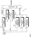
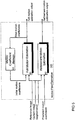
- Figure 1 illustrates an encoder 10 having a motion estimation block and
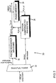
- Figure 2 illustrates a corresponding decoder 30.
- Motion compensated prediction in such a system is outlined below.
- Motion compensated (MC) prediction is a widely recognised compression technique. It utilises the fact that in a typical video sequence, pixel (pel) values in a particular frame can be predicted using pixel values of some other already coded and transmitted frame, given the motion trajectory between these two frames.
- the reference frame R n ( x , y ) is a frame the information for which has previously been coded and transmitted in order that it may be re-constructed in the decoder. Therefore, it may be a frame preceding the one being coded available that is in a frame memory of both the encoder 10 and the decoder 30.
- the pair of values [ ⁇ x ( x , y ), ⁇ y ( x , y )] represents the motion vector of the pixel in location ( x , y ) in the current frame.
- ⁇ x ( x , y ) and ⁇ y ( x , y ) are the values of horizontal and vertical displacements of this pixel, respectively.
- Motion vectors are calculated by a motion field estimation block 12 in the encoder 10 as can be seen in Figure 1 .
- the set of motion vectors of all pixels of the current frame [ ⁇ x ( ⁇ ), ⁇ y ( ⁇ )] is called the motion vector field and is calculated in a motion field coding block 14 before being used to calculate the prediction frame P n ( x , y ) in a motion compensated prediction block 16.
- the motion vector field is also transmitted to the decoder 30.
- a subtractor 18 determines the prediction error E n ( x , y ) between the prediction frame P n ( x , y ) and the frame being coded I n ( x , y ) according to equation 1. Once calculated, the prediction error E n ( x , y ) is compressed in a prediction error coding block 20 to produce a compressed prediction error, denoted by ⁇ n ( x , y ), which is then sent to the decoder 30.
- the compression process typically introduces some loss of information.
- the compressed prediction error ⁇ n ( x , y ) is decoded in a prediction error decoding block 22 so that it is used to generate a reference frame R n ( x , y ) in the encoder 10 which corresponds to the reference frame R n ( x , y ) which is generated in the decoder 30.
- this is done by combining the decoded prediction error ⁇ n ( x , y ) with the prediction frame P n ( x , y ) in an adder 24 to produce the reference frame R n ( x , y ).
- the reference frame R n ( x , y ) is stored in the frame memory 26 of the encoder 10.
- Motion information derived from the motion field coding block 14 and prediction error information derived from the prediction error coding block 20 are combined together in a multiplexing block 28.
- Figure 2 shows a decoder 30.
- a demultiplexer 32 separates the prediction error information and the motion information.
- the prediction error information is provided to a prediction error decoding block 34 and the motion information is provided to a motion compensated prediction block 36.
- the motion compensated prediction block 36 uses motion information and the reference frame R n ( x , y ) stored in the frame memory 38 of the decoder 30 to reconstruct the prediction frame P n ( x , y ).
- segments include at least a few tens of pixels.
- motion vector field model Such a function is called a motion vector field model.
- Polynomial motion models are a widely used family of motion models.
- CMM Mathematique
- motion vectors are described by functions which are linear combinations of 2-dimensional polynomial functions.
- the translational motion model is the simplest model and requires only two coefficients to describe motion vectors of each segment.
- the affine motion model presents a very convenient trade-off between the number of motion coefficients and prediction performance. It is capable of representing some of the common real-life motion types such as translation, rotation, zoom and shear by only a few coefficients.
- the quadratic motion model provides good prediction performance, but it is less popular in coding than the affine model, since it uses more motion coefficients, while the prediction performance is not much better.
- the motion estimation block calculates motion vectors [ ⁇ x ( x , y ), ⁇ y ( x , y )] of the pixels of a given segment S k which minimise some measure of prediction error in the segment.
- a meaningful additive measure of prediction error has the form: ⁇ x i y i ⁇ S k p i h I n x y ⁇ R n x + ⁇ x x y , y + ⁇ y x y
- p i values are scalar constants,
- Equation (9) is a highly non-linear function of many variables and there is thus no practical technique which is capable of always finding the absolute minimum of equation (9) in an acceptable time. Accordingly, motion estimation techniques differ depending on the algorithm for minimisation of the chosen measure of prediction error. Equation (10) is conventionally used as a cost function in motion estimation.
- One technique is the full search. In this technique the value of the cost function is calculated for all the possible combinations of allowed motion coefficient values (restricted by the range and precision with which motion coefficients can be represented). The values of motion coefficients for which the cost function is minimised are chosen to represent the motion vector field.
- the full search technique is usually used only to estimate motion coefficients of the translational motion model and cannot be straightforwardly generalised for other motion models, due to computational burden.
- the computational complexity of the algorithm increases exponentially with the number of motion coefficients used to represent the motion vector field.
- the nth iteration step consists of:
- the main problem associated with the Gauss-Newton algorithm is that it converges only towards local minima, unless the initial motion coefficients lie in the attraction domain of the global minimum. Thus it is necessary to provide the Gauss-Newton algorithm with a sufficiently good initial guess of the actual optimum. Two different techniques are usually used to improve the convergence of the Gauss-Newton algorithm:
- the technique of motion estimation using multi-resolution image pyramids is based on the assumption that low-pass filtering the current frame and the reference frame will erase the local minima and help the algorithm to converge to the global minimum.
- Motion estimation is performed first on the low-pass filtered (smoothed) versions of the reference and current frames, and the result is fed as input to the motion estimation stages using less smoothed images.
- the final estimation is performed on non-smoothed images.
- Some variants of this class additionally down-sample the low-pass filtered images, to reduce the number of computations. For examples of this technique, see H. Sanson, "Region based motion estimation and compensation for digital TV sequence coding," in Proc.
- low-pass filtering of the images does not necessarily erase local minima. Furthermore, this may shift the location of global minimum.
- EP0691789 discloses motion estimation, segmentation and coding.
- the method of motion estimation and segmentation of Figure 3 involves a hierarchical approach in which a motion vector updating routine is performed with respect to multiple levels of smaller and smaller regions of a frame.
- the method of processing a frame begins in step 300 at which point it is assumed that a preceding frame exists with reference to which a current frame can be predicted.
- the current frame is segmented or divided into smaller regions of a predetermined shape. This segmentation represents a first segmentation level. Where the predetermined shape is rectangular, the frame may be divided into multiple regions of predetermined equal size.
- the initial motion vector assigned to each of the smaller regions is the motion vector with value zero.
- a frame 400 is divided into multiple regions, each of which is rectangular and has an initial motion vector of zero. The choice of an initial motion vector with value zero is made to lessen the likelihood that noise will be introduced.
- the motion vector of each smaller region is updated according to a motion vector updating routine.
- the next step depends upon whether all the regions in the current segmentation level have been processed according to the motion vector updating routine as indicated in step 320. If all the regions have not been processed, then, as indicated in step 325, the remaining regions are processed serially.
- the preferred sequence begins with a corner region, such as the region corresponding to the upper-left of the current frame. The sequence then proceeds across the upper row to the region corresponding to the upper-right of the current frame. Each subsequent row of regions is processed from left to right until the region corresponding to the lower-right of the current frame has been processed.
- the first step in the motion vector updating routine is shown in step 330 in which a matching error is computed for the current region under consideration by using the initial motion vector assigned to that region.
- the initial motion vector assigned to the current region may be temporarily stored in the file 221 of the memory unit 220 by retrieving it from the motion field memory unit 215.
- the matching error obtained in step 330 is stored in one of the files 241-250 in the memory unit 240.
- step 335 a motion estimation technique is performed with respect to the region under consideration.
- One type of suitable motion estimation technique for use in step 335 involves block matching methods.
- the block matching motion estimation technique is performed for the region under consideration and finds a best matched region in the preceding frame within a predetermined search range. For very low bit-rate applications, search ranges of between ⁇ 7 and ⁇ 15 pixels are suitable.
- the block matching technique performed in step 335 results in a matched motion vector which serves as one of the candidates for refining or updating the motion vector of the particular region under consideration.
- the matched motion vector is a two dimensional vector representing the distance between the location of the current region and the location of the best matched region in the preceding frame.
- GB2317525 discloses a motion estimation system for a video coder. It comprises an input for a video image to be coded, and a series of motion estimators of varying complexity, for estimating a motion vector field between the received image and a reference image. The subsequent motion estimator in the series is selected by a control means if a prediction error associated with the motion vector field estimated by the currently selected motion estimator exceeds a predetermined threshold.
- the invention takes advantage of motion information already available when entering the motion estimation stage. This additional motion information may be predicted from neighbouring segments or inherited from earlier motion estimations for master segments overlapping with the picture element for which motion is to be estimated.
- the motion field estimation means calculates motion coefficients for the at least one picture element by using a set of prediction motion coefficients previously estimated for at least one neighbouring picture element. It may use more than one neighbouring picture element. In this case, it can use an averaged set of prediction motion coefficients averaged from motion information previously estimated for more than one neighbouring picture element.
- nneighbouringn refers to adjacent picture elements in which at least one pixel of one picture element' is directly so next to or overlaps with at least one pixel of another picture element.
- the encoder comprises segmentation means for segmenting a received frame into a plurality of picture elements.
- the segmentation means may derive initial motion coefficients for a master picture element.
- the picture elements are segments.
- the encoder comprises two separate motion estimators, one motion estimator for estimating motion coefficients based upon the predicted motion coefficients and one motion estimator for estimating motion coefficients based on the initial motion coefficients. If the prediction motion coefficients and the initial motion coefficients are both available both of the motion estimators may estimate motion coefficients. In this case, selection means in the encoder may select motion coefficients from either motion estimator to be used to code the current frame. However, if only one set of motion coefficients are available and those of the other motion estimator are not available, one motion estimator estimates motion coefficients.
- the encoder is able to use a combination of the motion estimators having relatively simple motion estimation methods which rely on different assumptions instead of one high complexity method relying on one assumption.
- the encoder determines whether a prediction error associated with motion coefficients estimated by a currently selected method of motion estimation exceeds a predetermined threshold and, if so, it selects a subsequent motion estimation method in a series.
- the encoder comprises a series of motion estimation methods of varying complexity.
- the series may comprises a hierarchy including a zero so motion model, a translational motion model, and an affine motion model.
- the encoder comprises a series of minimisers, including a segment matching minimiser and a Gauss-Newton minimiser and a Quasi-Newton minimiser.
- the encoder dynamically switches between statistically valid assumptions varying in strength. In this way it can achieve statistically low prediction error with relatively little complexity.
- the encoder comprises means for sub-sampling the current frame to produce a sub-sampled frame and for forwarding the sub-sampled frame to the series of motion models.
- the means for sub-sampling may comprise a series of sub-samplers varying in sub-sampling factors.
- the encoder may also comprise control means for selecting and using a subsequent motion model in the series if a prediction error associated with the motion vector field estimated by a currently selected motion estimator unit exceeds a predetermined threshold.
- the control means may be provided to select the amount of sub-sampling during minimisation depending on the change in prediction error.
- the encoder has receiving means for receiving a current frame to be motion coded.
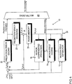
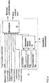
- FIG. 4 An encoder 10 according to the invention is shown in Figure 4 . This figure is similar to Figure 1 and the preceding description applies.
- the encoder of Figure 4 operates in conjunction with a decoder corresponding to that of Figure 2 .
- Figure 4 will now be described.
- Block-based segmentation in the motion field coding block 14 is used in the embodiment of the invention which will now be described.
- Final segmentation consists of 16x16 pixel macro-blocks and 8x8 pixel sub-blocks.
- the prediction error is analysed in the motion field estimation block 12 and a decision is made in the motion field estimation block 12 whether to split the macro-block into four 8x8 sub-blocks. If splitting takes place, motion coefficients of the macro-block are kept in a motion coefficient memory of the motion field estimation block 12 and used as initial motion coefficients in the 8x8 motion estimation. This is described below. Irrespective of whether splitting takes place, final motion coefficients of the macro-block are output to the motion field coding block 14.
- the motion field coding block 14 makes the final decisions on the motion model to be transmitted, whether to use a single 16x16 block or four 8x8 blocks to describe this (16x16) macroblock and the coding of the motion coefficients.
- the same motion estimation system is used independent of the size of the block for which motion is estimated.
- motion information produced by the motion field coding block 14 is fed back to the motion field estimation block 12.
- This motion information comprises both initial motion coefficients and predicted motion coefficients relating to motion of a segment in the current frame relative to a segment in the reference frame.
- This feedback is represented by numeral 30.
- Use of the motion information by the motion field estimation block will be described below.
- the motion field estimation block 12 is shown in Figure 5 .
- This block comprises two motion estimation blocks, namely a full motion estimation block 41 and a refinement motion estimation block 42 and a motion coefficient memory 43.
- motion is first estimated for a 32x32 pixel block in the full motion estimation block 41.
- the resulting motion coefficients are stored in the motion coefficient memory 43 and retrieved and used as initial motion coefficients for the segments (16x16 macro-blocks or 8x8 sub-blocks) created by splitting a previously estimated block.
- the full motion estimation block 41 calculates motion coefficients based on the difference between a current frame and an earlier reference frame.
- the full motion estimation block 41 can include these as a basis to calculate motion coefficients for a segment of the current frame.
- the refinement motion estimation block 42 calculates motion coefficients for a segment of a current frame based on motion coefficients predicted for a segment of the current frame which have previously been calculated.
- the full motion estimation block 41 and the refinement motion estimation block 42 are used. Operation of the motion estimation blocks 41 and 42 is described in greater detail later on with reference to Figures 10 and 11 .
- both motion estimation blocks consist of four main blocks, namely a sub-sampling block 51, a motion model selector block 52, a cost function minimiser block 53 and a result verification block 54.
- the result verification block 54 produces a number of switch signals to control operation of the other three blocks, 51, 52, and 53. Each of these blocks is described below.
- the full motion estimation block 41 and the refinement motion estimation block 42 work in steps. At each step, the motion model, the minimisation method used to minimise the cost function value and the sub-sampling factor are determined. These determinations are made in the result verification block 54 of Figure 6 of the respective motion estimation block.
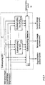
- Figure 7 shows a block diagram of the sub-sampling block 51.
- the inputs to this block are the reference frame R n ( x , y ) from the frame memory 26 of the encoder 10, the current frame I n ( x , y ), segmentation information from the motion field coding block 14, and information about the required level of sub-sampling. This is provided by a sub-sampling switch signal 55 which is described below.
- the sub-sampling block 51 consists of a bank 61 of sub-samplers 61(1) to 61 (k) and a sub-sampling selector 62 in the form of a multiplexer.
- Each sub-sampler 61(1) to 61 (k) (denoted "Sub-sampling by mxm ”) in the bank 61 subsamples both the reference image and the current image by taking every m th pixel in both horizontal and vertical directions, where m is an integer power of 2.
- the inputs to the sub-sampling selector 62 are the reference R n ( x,y ) and current I n ( x , y ) frames, segmentation information and their sub-sampled versions at various levels, that is a version which has not been sampled and versions sub-sampled by each of the sub-samplers 61(1) to 61 (k).
- the sub-sampling selector uses the sub-sampling switch signal 55 to select an image pair and suitable segmentation to be output.
- the result verification block 54 ( Figure 6 ) is responsible for generating consistent switch signals.
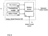
- Figure 8 shows a preferred motion model selector block 52.
- the motion model selector block 52 comprises a motion model multiplexer 71 and a bank 72 of motion models.
- the motion model selector block 52 receives a motion model switch signal 73 from the result verification block 54.
- the motion model selection block 52 is a multiplexer, which makes a selection among the bank 72 of motion models 72a to 72c depending on the motion model switch signal 73.
- the motion models in the bank 72 are "No motion” 72a, "Translational model” 72b and "Affine model” 72c in order of increasing complexity.
- the order of complexity refers to the number of basis functions used in representing the motion. There is a close relationship between the order of complexity of the motion model and computational complexity: as the order of complexity of the motion model increases, the computational complexity of estimation of model coefficients increases.
- there is a "No motion" model72a for which all the motion coefficients are set to zero.
- Other motion models may be used, for example the quadratic motion model. Alternatively, this could be an additionally used model.
- FIG. 9 shows the block diagram of the cost function minimiser block 53. Minimisation of the cost function is performed in this block. It comprises a minimisation method selector 81, a bank 82 of minimisation methods and a minimisation block 83 which calculates a motion coefficient vector and its associated minimised cost function vector.
- the minimisation methods comprise "No minimisation” 82a, "Segment matching” 82b and "Gauss-Newton step” 82c. These minimisation methods are further described below.
- the inputs to the cost function minimiser block 53 are:
- This cost function minimiser block 53 performs minimisation by one of the methods in its bank 82. The selection of the method is determined by a minimisation method switch signal 80 provided by the result verification block 54.
- No minimisation 82a may be selected for any motion model.
- the cost function minimiser block 53 does not perform any cost function optimisation but simply returns the value of the cost function with motion coefficients inputted. This method is used to evaluate the cost function value in the presence of initial motion parameters.
- Segment matching 82b can be selected only for the translational motion model.
- the value of the cost function is calculated for the selected set of values of motion coefficients a 0 and b 0 .
- the values of a 0 and b 0 which yield the smallest value of the prediction error in (6) are chosen as the solution.
- the search is performed on a quantized grid, that is, only the scalar quantized values of a 0 and b 0 are used.
- the search is made by evaluating some or all of the candidate pairs on the grid, and choosing the pair yielding the smallest cost function value.
- Gauss-Newton step 82c can be used for any motion model except “No Motion”. It uses a single Gauss-Newton iteration step to reduce the cost function.
- R. Fletcher Practical Methods of Optimization", Second Edition, John Wiley & Sons, 1987, Chapter 3 and Chapter 6 gives an overview of Gauss-Newton minimisati on.
- the Gauss-Newton method is a specific form of Newton's method, commonly used when the cost function to be minimised is a sum of squares.
- e ( a ) be the cost function as a function of parameter vector a .
- a c be the current parameter vector, being input to the minimisation iteration.
- the Gauss-Newton method approximates the second derivative matrix G by: G ⁇ 2 ⁇ d ⁇ d T where ⁇ d denotes the Jacobian matrix, the columns of which are the first derivative vectors ⁇ d i of the components of d .
- the Gauss-Newton method is not very costly computationally, since it performs only one iteration step.
- the cost function minimiser 53 outputs a minimised cost function value and a motion coefficient vector.
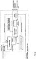
- FIG. 6 shows the details of the full motion estimation 41 and the refinement motion estimation 42 blocks of Figure 5 .
- the verification block 54 provides switch signals.
- the switch signals include the sub-sampling switch signals 55, the motion model switch signal 73, and the minimisation method switch signal 80 which select the sub-sampling factor, motion model and minimisation model, respectively, to be used in the current iteration.
- Any combination of switch signals generated by the result verification block 54 has an underlying set of assumptions.
- the purpose of the result verification block 54 is to optimise these assumptions. Once the set of assumptions is determined, a new set of switch signals is generated and new motion coefficients and a new cost function value result. By comparing these to the previous ones, the result verification block 54 determines:
- switch signals control other blocks in the system. Therefore, determination of the switch signals determines the motion model, minimisation method, and sub-sampling factor to be used in the next iteration(s).
- the result verification block 54 keeps the "current motion coefficients", which are the motion coefficients yielding the smallest value of the cost function so far, and a "current cost function value” which is the smallest value of the cost function so far. If iterations are continued, the current motion coefficients and current cost function value are fed to cost function minimiser 53.
- a convergence flag signal 56 is set by the result verification block 54, and then it outputs the convergence flag signal 56 together with the current motion coefficients as "final motion coefficients" 57 and current cost function value as "final cost function value” 58. These outputs are sent to the motion field coding block 14.
- the result verification block 54 is a powerful tool for keeping the computational complexity of the system at a minimum. By context-dependent switching between sets of assumptions, that is, particular sets of motion models, minimisation methods and degrees of sub-sampling, this block allows high performance motion estimation, involving computationally complex techniques only when necessary.
- the system can find motion coefficients of a segment for:
- the system can be implemented in a variety of ways. For example, the following features may vary:
- only one sub-sampler 61 is provided in the sub-sampling block 51. This sub-sampler causes the signal to be sub-sampled by 2x2.
- the sub-sampling switch signal 55 either chooses this sub-sampler or no sub-sampling at all.
- the motion model selector's bank 72 there are three motion models in the motion model selector's bank 72: the "No motion” model 72a, the “Translational model” 72b and the “Affine model” 72c.
- the segment matching 82a performed is "full-pel segment matching with full search". This operation requires testing all integer-valued motion coefficient pairs in a certain range to find the pair minimising the cost function.
- the Gauss-Newton step is employed only when the motion model is affine.
- Cubic convolution interpolation is used for sub-pixel evaluation.
- Image derivatives are also computed using cubic convolution: the derivatives of the continuous function obtained by cubic convolution interpolation are computed, and they are interpreted as the image derivatives.
- the generation of the new switch signals in the result verification blocks 54 of the full motion estimation block 41 and the refinement motion estimation block 42 can be done in a number of ways. Preferred ways for both motion estimation blocks to generate switch signals are described below.
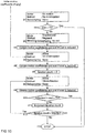
- Figure 10 shows the flow diagram of operations performed in the result verification block 54 of the full motion estimation block 41 according to the preferred embodiment of the invention.
- a first set of assumption (91) of "No motion” are set by switching the sub-sampling level to "None”, the minimisation method is set to "No minimisation” and motion model to "No motion”. If the resulting cost function is below a predefined threshold (92) (denoted “Th1" in Figure 10 ), the search is terminated (913) with zero motion coefficients.
- the next set of assumptions (93) are that a "translational model can approximate the actual motion field" and that "sub-sampling does not shift the global minimum substantially”.
- the sub-sampling switch signal 55 is set to "Sub-sampling by 2x2”
- the model is switched to "Translational model”
- the cost function minimisation method is set to "Segment matching” (93) (sub-sampling is performed to reduce the complexity of operation).
- the best-so-far coefficients are updated (94) by setting the values of a 0 and b 0 in equation 7 to the values computed by segment matching, and setting the other coefficients to zero.
- step 94 If initial motion coefficients are available, for example from a master segment (and stored in the motion coefficient memory block 43), the next assumption is that an "affine model with initial motion coefficients can approximate the actual motion" (95). Now, the motion model is set to "Affine”, “No minimisation” is selected as the minimisation method and the sub-sampling switch signal 55 is set to "None”. Again the cost is evaluated using equation (10) and, if the cost is smaller that the minimum cost of the previous stages (96), initial motion coefficients are stored as the best so far. If there are no initial motion coefficients available, steps 95 and 96 do not occur and step 97 follows step 94.
- the cost function associated with the outcome of the iteration is compared (99) to the best cost function so far obtained. If the resulting cost function is less than the best-so-far cost function, the motion coefficients and best-so-far cost function value are updated by the outcomes of the iteration.
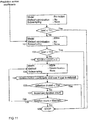
- Figure 11 shows a flow diagram of operations performed in the result verification block 54 of the refinement motion estimation block 42 in the preferred embodiment of the method according to the invention. It can be seen that operations are similar to those performed in Figure 10 .
- the first assumption is "No motion” and, if the resulting cost function value associated with this assumption is below the predefined threshold Th1 (the same as in Figure 10 ), the search is terminated (913) with zero motion coefficients.
- the second assumption is that "the incoming set of predicted motion coefficients already approximates final motion coefficients 52 reasonably well” (101).
- An initial cost is evaluated and compared against a predefined threshold Th3 (102). If the cost is below the threshold, the input motion coefficients are outputted as such (109) and sent to the motion field coding block 14.
- both the full motion estimation block 41 and the refinement motion estimation block 42 are operational (that is if both initial motion coefficients and predicted motion coefficients are available), then, upon receipt of the outputs of these blocks, the motion field coding block 14 compares the "final cost function values" in order to choose one set of motion coefficients to be used.
- a suitable way of comparing these motion coefficients is described in co-pending US patent application titled “Adaptive motion vector field coding” by inventors Jani Lainema and Marta Karczewicz, filed 21 January 2000.
- the predefined thresholds may differ, at different stages of minimisation and/or for different models and/or for different bitrates.
- the system for motion estimation according to the present invention achieves motion estimation with significantly less prediction error than that of previous solutions, while keeping the computational complexity at a statistically low level. This is achieved by providing dynamic switching between statistically valid assumptions varying in strength, via assumption verification at each iteration.
- the present invention specifically provides an improved system for motion estimation of an image segment, using a polynomial motion vector field model.
- Motion estimation is an element of video coding using motion compensated prediction.
- the system finds motion coefficients which yield lower prediction error than prior art solutions, while keeping the computational complexity low.
- This low prediction error enables better performance in terms of video compression.
- the low prediction error is achieved by incorporating the general characteristics of image data and motion into a combination of well-known function minimisation techniques.
Landscapes
- Engineering & Computer Science (AREA)
- Multimedia (AREA)
- Signal Processing (AREA)
- Theoretical Computer Science (AREA)
- Computer Vision & Pattern Recognition (AREA)
- Physics & Mathematics (AREA)
- General Physics & Mathematics (AREA)
- Computing Systems (AREA)
- Compression Or Coding Systems Of Tv Signals (AREA)
- Compression, Expansion, Code Conversion, And Decoders (AREA)
Description
- The present invention relates to a video coding system. In particular, it relates to a system for the compression of video sequences using motion compensated prediction.
-
Figure 1 andFigure 2 are schematic diagrams of a system using motion compensated prediction.Figure 1 illustrates anencoder 10 having a motion estimation block andFigure 2 illustrates acorresponding decoder 30. Motion compensated prediction in such a system is outlined below. - In typical video sequences the change of the content of successive frames is to a great extent the result of motion in the scene. This motion may be due to camera motion or due to motion of the objects present in the scene. Therefore typical video sequences are characterised by significant temporal correlation, which is highest along the trajectory of the motion. Efficient compression of video sequences requires exploitation of this property.
- Motion compensated (MC) prediction is a widely recognised compression technique. It utilises the fact that in a typical video sequence, pixel (pel) values in a particular frame can be predicted using pixel values of some other already coded and transmitted frame, given the motion trajectory between these two frames.
- A motion compensation system will now be described with reference to
Figures 1 and2 . The operating principle of motion compensated video coders is to minimise the prediction error En (x,y), that is, the difference between the frame being coded In (x,y), called the current frame, and a prediction frame Pn (x,y):
- The prediction frame Pn (x,y) is built using pixel values of a reference frame denoted by Rn (x,y) and the motion vectors of pixels between the current frame and the reference frame using the equation:

- The reference frame Rn (x,y) is a frame the information for which has previously been coded and transmitted in order that it may be re-constructed in the decoder. Therefore, it may be a frame preceding the one being coded available that is in a frame memory of both the
encoder 10 and thedecoder 30. The pair of values [Δx(x,y),Δy(x,y)] represents the motion vector of the pixel in location (x,y) in the current frame. Δx(x,y) and Δy(x,y) are the values of horizontal and vertical displacements of this pixel, respectively. Motion vectors are calculated by a motionfield estimation block 12 in theencoder 10 as can be seen inFigure 1 . The set of motion vectors of all pixels of the current frame [Δx(·),Δy(·)] is called the motion vector field and is calculated in a motionfield coding block 14 before being used to calculate the prediction frame Pn (x,y) in a motion compensatedprediction block 16. The motion vector field is also transmitted to thedecoder 30. - Referring again to
Figure 1 , asubtractor 18 determines the prediction error En (x,y) between the prediction frame Pn (x,y) and the frame being coded In (x,y) according toequation 1. Once calculated, the prediction error En (x,y) is compressed in a predictionerror coding block 20 to produce a compressed prediction error, denoted by Ẽn (x,y), which is then sent to thedecoder 30. - The compression process typically introduces some loss of information.
- Therefore, the compressed prediction error Ẽn (x,y) is decoded in a prediction
error decoding block 22 so that it is used to generate a reference frame Rn (x,y) in theencoder 10 which corresponds to the reference frame Rn (x,y) which is generated in thedecoder 30. In theencoder 10 this is done by combining the decoded prediction error Ẽn (x,y) with the prediction frame Pn (x,y) in anadder 24 to produce the reference frame Rn (x,y). The reference frame Rn (x,y) is stored in theframe memory 26 of theencoder 10. - Motion information derived from the motion
field coding block 14 and prediction error information derived from the predictionerror coding block 20 are combined together in amultiplexing block 28. -
Figure 2 shows adecoder 30. Ademultiplexer 32 separates the prediction error information and the motion information. The prediction error information is provided to a predictionerror decoding block 34 and the motion information is provided to a motion compensatedprediction block 36. The motion compensatedprediction block 36 uses motion information and the reference frame Rn (x,y) stored in the frame memory 38 of thedecoder 30 to reconstruct the prediction frame Pn (x,y). Pixels of the coded current frame Ĩn (x,y) are then reconstructed by adding the prediction frame Pn (x,y) to the received prediction error Ẽn (x,y) in an adder 40, that is:
- Due to the very large number of pixels in the frame it is not efficient to transmit a separate motion vector for each pixel. Instead, in most video coding schemes the current frame is divided into larger image segments so that all motion vectors of the segment can be described by fewer coefficients. Depending on the way the current frame is divided into the segments two types of motion compensated coders can be distinguished:
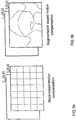
- 1. Block based coders where the current frame is divided into fixed and a priori known blocks (see
Figure 3a ), for example 16x16 pixel blocks in codecs according to international standard ISO/IEC MPEG-1 or ITU-T H.261; and - 2. Segmentation based (region based) coders where the current frame is divided into arbitrarily shaped segments (see
Figure 3b ), for example obtained by a segmentation algorithm. For examples refer to Centre de Morphologie Mathematique (CMM), "Segmentation algorithm by multicriteria region merging," Document SIM(95)19, COST 211ter Project Meeting, May 1995 and P. Cicconi and H. Nicolas, "Efficient region-based motion estimation and symmetry oriented segmentation for image sequence coding," IEEE Transactions on Circuits and Systems for Video Technology, Vol. 4, No. 3, June 1994, pp. 357-364. - In practice, segments include at least a few tens of pixels. In order to represent the motion vectors of these pixels compactly it is desirable that their values are described by a function of a few coefficients. Such a function is called a motion vector field model.
- Almost all the motion vector field models commonly used are additive motion models. Motion compensated video coding schemes may define the motion vectors of image segments according to the following general equations:


- In order to minimise the amount of information needed in sending the motion coefficients to the decoder, not all motion coefficients for all segments are transmitted. This may be the case, for example, where certain motion coefficients can be omitted without causing significant error. Instead, some of the motion coefficients for some segments are transmitted and others are not transmitted.
- Polynomial motion models are a widely used family of motion models. (See, for example H. Nguyen and E. Dubois, "Representation of motion information for image coding," in Proc. Picture Coding Symposium '90, Cambridge, Massachusetts, March 26-18, 1990, pp. 841-845 and Centre de Morphologie Mathematique (CMM), "Segmentation algorithm by multicriteria region merging," Document SIM(95)19, COST 211ter Project Meeting, May 1995).
- The values of motion vectors are described by functions which are linear combinations of 2-dimensional polynomial functions. The translational motion model is the simplest model and requires only two coefficients to describe motion vectors of each segment. The values of motion vectors are given by the equations:

- This model is used in international standards (ISO MPEG-1, MPEG-2, MPEG-4, ITU-T Recommendations H.261 and H.263) to describe motion of 8x8 and 16x16 blocks. Two other widely used models are the affine motion model given by the equation:


- The affine motion model presents a very convenient trade-off between the number of motion coefficients and prediction performance. It is capable of representing some of the common real-life motion types such as translation, rotation, zoom and shear by only a few coefficients.
- The quadratic motion model provides good prediction performance, but it is less popular in coding than the affine model, since it uses more motion coefficients, while the prediction performance is not much better.
- Furthermore, it is computationally more costly to estimate motion using a quadratic model than it is to estimate affine motion.
- The motion estimation block calculates motion vectors [Δx(x,y),Δy(x,y)] of the pixels of a given segment Sk which minimise some measure of prediction error in the segment. A meaningful additive measure of prediction error has the form:


- Equation (9) is a highly non-linear function of many variables and there is thus no practical technique which is capable of always finding the absolute minimum of equation (9) in an acceptable time. Accordingly, motion estimation techniques differ depending on the algorithm for minimisation of the chosen measure of prediction error. Equation (10) is conventionally used as a cost function in motion estimation.
- Previously known techniques for motion estimation are discussed below.
- One technique is the full search. In this technique the value of the cost function is calculated for all the possible combinations of allowed motion coefficient values (restricted by the range and precision with which motion coefficients can be represented). The values of motion coefficients for which the cost function is minimised are chosen to represent the motion vector field.
- The full search technique is usually used only to estimate motion coefficients of the translational motion model and cannot be straightforwardly generalised for other motion models, due to computational burden. In a straightforward generalisation, the computational complexity of the algorithm increases exponentially with the number of motion coefficients used to represent the motion vector field.
- Motion estimation using Gauss-Newton iterations (or differential optimisation schemes) is an alternative. These are outlined in H. Sanson, "Region based motion estimation and compensation for digital TV sequence coding," in Proc. Picture Coding Symposium '93, Lausanne, Switzerland, March 17-19, 1993 and C. A. Papadoupoulos, and T. G. Clarkson, "Motion Compensation Using Second-Order Geometric Transformations", IEEE Transactions on Circuits and Systems for Video Technology, Vol. 5, No. 4, August 1995, pp. 319-331. Such techniques use the well-known Gauss-Newton function minimisation algorithm, to minimise the cost function (9), that is the chosen measure of prediction error, as a function of motion coefficients.
- This algorithm assumes that the function to be minimised can be locally approximated by a quadratic function of the arguments. Then, the nth iteration step consists of:
- 1. computing an approximate quadratic function using first and second derivatives of the actual function using the motion coefficient resulting from (n-1)th step,
- 2. computing the coefficient vector minimising the approximate function, and assigning the result to the motion coefficient of nth step.
- The main problem associated with the Gauss-Newton algorithm is that it converges only towards local minima, unless the initial motion coefficients lie in the attraction domain of the global minimum. Thus it is necessary to provide the Gauss-Newton algorithm with a sufficiently good initial guess of the actual optimum. Two different techniques are usually used to improve the convergence of the Gauss-Newton algorithm:
- 1. motion estimation using multi-resolution image pyramids, motion estimation using hierarchically increasing levels of the motion model.
- The technique of motion estimation using multi-resolution image pyramids is based on the assumption that low-pass filtering the current frame and the reference frame will erase the local minima and help the algorithm to converge to the global minimum. Motion estimation is performed first on the low-pass filtered (smoothed) versions of the reference and current frames, and the result is fed as input to the motion estimation stages using less smoothed images. The final estimation is performed on non-smoothed images. Some variants of this class additionally down-sample the low-pass filtered images, to reduce the number of computations. For examples of this technique, see H. Sanson, "Region based motion estimation and compensation for digital TV sequence coding," in Proc. Picture Coding Symposium '93, Lausanne, Switzerland, March 17-19, 1993 and P. J. Burt, "The Pyramid as a Structure for Efficient Computation", in: Multiresolution Image Processing and Analysis, ed. Rosenfeld, Springer Verlag, 1984, pp. 6-35.
- However, low-pass filtering of the images does not necessarily erase local minima. Furthermore, this may shift the location of global minimum.
- In contrast, the technique of motion estimation using hierarchically increasing levels of the motion model makes use of the following assumptions:
- 1. A complex motion model can be approximated by a lower order motion model.
- 2. This approximation is a good initial guess for the iterative search for more complex motion model coefficients.
- The most common hierarchy starts with the translational model (2 coefficients), then continues with a simplified linear model (corresponding to the physical motion of translation, rotation and zoom, having 4 coefficients), and ends with the complete linear model (6 coefficients). Such a hierarchy can be seen in P. Cicconi and H. Nicolas, "Efficient region-based motion estimation and symmetry oriented segmentation for image sequence coding," IEEE Transactions on Circuits and Systems for Video Technology, Vol. 4, No. 3, June 1994, pp. 357-364 and H. Nicolas and C. Labit, "Region-based motion estimation using deterministic relaxation schemes for image sequence coding," in Proc. 1994 International Conference on Acoustics, Speech and Signal Processing, pp. III265-268.
- These assumptions can work very well under certain conditions. However, convergence to a local minimum is often a problem, especially in the case when the approximation turns out to be a poor one.
- Present systems, such as those outlined above, suffer from disadvantages resulting from the relationship between computational complexity and video compression performance. That is, on the one hand, an encoder will require a motion estimation block having high computational complexity in order to determine motion coefficients which minimise the chosen measure of prediction error (9) and thus achieve the appropriate video compression performance. Usually, in this case such a motion estimation block acts as a bottleneck for computational complexity of the overall encoder, due to the huge number of computations required to achieve the solution.
- On the other hand, if computational complexity is reduced, this causes a reduction in prediction performance, and thus video compression performance. Since the prediction performance of motion estimation heavily affects the overall compression performance of the encoder, it is crucial for a motion estimation algorithm to have high prediction performance (that is low prediction error) with relatively low complexity.
- To keep the complexity low, motion estimation algorithms make assumptions about the image data, motion, and prediction error. The more these assumptions hold statistically, and the stronger the assumptions are, the better the algorithm. Different sets of assumptions usually result in different minimisation techniques.
-
EP0691789 discloses motion estimation, segmentation and coding. The method of motion estimation and segmentation ofFigure 3 involves a hierarchical approach in which a motion vector updating routine is performed with respect to multiple levels of smaller and smaller regions of a frame. The method of processing a frame begins in step 300 at which point it is assumed that a preceding frame exists with reference to which a current frame can be predicted. In step 305, the current frame is segmented or divided into smaller regions of a predetermined shape. This segmentation represents a first segmentation level. Where the predetermined shape is rectangular, the frame may be divided into multiple regions of predetermined equal size. - The first time that step 310 is performed, the initial motion vector assigned to each of the smaller regions is the motion vector with value zero. At a first level segmentation a frame 400
is divided into multiple regions, each of which is rectangular and has an initial motion vector of zero. The choice of an initial motion vector with value zero is made to lessen the likelihood that noise will be introduced. - The motion vector of each smaller region is updated according to a motion vector updating routine. The next step depends upon whether all the regions in the current segmentation level have been processed according to the motion vector updating routine as indicated in step 320. If all the regions have not been processed, then, as indicated in step 325, the remaining regions are processed serially. The preferred sequence begins with a corner region, such as the region corresponding to the upper-left of the current frame. The sequence then proceeds across the upper row to the region corresponding to the upper-right of the current frame. Each subsequent row of regions is processed from left to right until the region corresponding to the lower-right of the current frame has been processed.
- The first step in the motion vector updating routine is shown in step 330 in which a matching error is computed for the current region under consideration by using the initial motion vector assigned to that region. The initial motion vector assigned to the current region may be temporarily stored in the file 221 of the memory unit 220 by retrieving it from the motion field memory unit 215. In step 332, the matching error obtained in step 330 is stored in one of the files 241-250 in the memory unit 240. Next, as shown in step 335, a motion estimation technique is performed with respect to the region under consideration.
- One type of suitable motion estimation technique for use in step 335 involves block matching methods. The block matching motion estimation technique is performed for the region under consideration and finds a best matched region in the preceding frame within a predetermined search range. For very low bit-rate applications, search ranges of between ±7 and ±15 pixels are suitable. The block matching technique performed in step 335 results in a matched motion vector which serves as one of the candidates for refining or updating the motion vector of the particular region under consideration. The matched motion vector is a two dimensional vector representing the distance between the location of the current region and the location of the best matched region in the preceding frame.
-
GB2317525 - The invention is defined in the appended claims.
- The invention takes advantage of motion information already available when
entering the motion estimation stage. This additional motion information may
be predicted from neighbouring segments or inherited from earlier motion
estimations for master segments overlapping with the picture element for
which motion is to be estimated. - The following text relates to the disclosure of this specification.
- The motion field estimation means calculates motion coefficients for
the at least one picture element by using a set of prediction motion
coefficients previously estimated for at least one neighbouring picture
element. It may use more than one neighbouring picture element. In this case,
it can use an averaged set of prediction motion coefficients averaged from
motion information previously estimated for more than one neighbouring
picture element. - When applied to picture elements, the term nneighbouringn refers to adjacent
picture elements in which at least one pixel of one picture element' is directly
so next to or overlaps with at least one pixel of another picture element. - The encoder comprises segmentation means for segmenting a
received frame into a plurality of picture elements. The segmentation means may derive initial motion coefficients for a master picture element. - The picture elements are segments.
- In one embodiment, the encoder comprises two separate motion estimators, one motion estimator for estimating motion coefficients based upon the predicted motion coefficients and one motion estimator for estimating motion coefficients based on the initial motion coefficients. If the prediction motion coefficients and the initial motion coefficients are both available both of the motion estimators may estimate motion coefficients. In this case, selection means in the encoder may select motion coefficients from either motion estimator to be used to code the current frame. However, if only one set of motion coefficients are available and those of the other motion estimator are not available, one motion estimator estimates motion coefficients.
- The encoder is able to use a combination of the motion estimators having relatively simple motion estimation methods which rely on different assumptions instead of one high complexity method relying on one assumption.
- The encoder determines whether a prediction error associated with
motion coefficients estimated by a currently selected method of motion estimation exceeds a predetermined threshold and, if so, it selects a subsequent motion estimation method in a series. - The encoder comprises a series of motion estimation methods of
varying complexity. The series may comprises a hierarchy including a zero so motion model, a translational motion model, and an affine motion model. - The encoder comprises a series of minimisers, including a segment matching minimiser and a Gauss-Newton minimiser and a Quasi-Newton minimiser.
- The encoder dynamically switches between statistically valid
assumptions varying in strength. In this way it can achieve statistically low prediction error with relatively little complexity. - The encoder comprises means for sub-sampling the current frame
to produce a sub-sampled frame and for forwarding the sub-sampled frame to the series of motion models. The means for sub-sampling may comprise a series of sub-samplers varying in sub-sampling factors. - The encoder may also comprise control means for selecting and using a subsequent motion model in the series if a prediction error associated with the motion vector field estimated by a currently selected motion estimator unit exceeds a predetermined threshold. The control means may be provided to select the amount of sub-sampling during minimisation depending on the change in prediction error.
- The encoder has receiving means for receiving a current frame to be motion coded.
- Embodiments of the present invention will now be described, by way of example only, with reference to the accompanying drawings, of which:
-
Figure 1 shows an encoder for the motion compensated coding of video frames; -
Figure 2 shows a decoder for the motion compensated coding of video frames; -
Figure 3(a) shows the division of a current frame for block based motion compensation; -
Figure 3(b) shows the division of a current frame for segmentation based motion compensation; -
Figure 4 shows an encoder for motion compensated coding of video frames according to the invention; -
Figure 5 shows a motion estimation system according to an embodiment of the invention; -
Figure 6 shows a motion estimation block shown present in the motion estimation system ofFigure 5 ; -
Figure 7 shows a sub-sampling block present in the motion estimation block ofFigure 6 ; -
Figure 8 is a block diagram of the motion model selector present in the motion so estimation block ofFigure 6 ; -
Figure 9 is a block diagram of the cost function minimiser present in the motion estimation block ofFigure 6 ; -
Figure 10 is a flow diagram of a preferred implementation of the result verification block of a full motion estimation block; and -
Figure 11 is a flow diagram of a preferred implementation of the result verification block of a refinement motion estimation block. - An
encoder 10 according to the invention is shown inFigure 4 . This figure is similar toFigure 1 and the preceding description applies. The encoder ofFigure 4 operates in conjunction with a decoder corresponding to that ofFigure 2 .Figure 4 will now be described. - Block-based segmentation in the motion
field coding block 14 is used in the embodiment of the invention which will now be described. Final segmentation consists of 16x16 pixel macro-blocks and 8x8 pixel sub-blocks. After estimating motion for a macro-block, the prediction error is analysed in the motionfield estimation block 12 and a decision is made in the motionfield estimation block 12 whether to split the macro-block into four 8x8 sub-blocks. If splitting takes place, motion coefficients of the macro-block are kept in a motion coefficient memory of the motionfield estimation block 12 and used as initial motion coefficients in the 8x8 motion estimation. This is described below. Irrespective of whether splitting takes place, final motion coefficients of the macro-block are output to the motionfield coding block 14. The motionfield coding block 14 makes the final decisions on the motion model to be transmitted, whether to use a single 16x16 block or four 8x8 blocks to describe this (16x16) macroblock and the coding of the motion coefficients. In this embodiment the same motion estimation system is used independent of the size of the block for which motion is estimated. - One significant difference between
Figure 1 andFigure 4 is that motion information produced by the motionfield coding block 14 is fed back to the motionfield estimation block 12. This motion information comprises both initial motion coefficients and predicted motion coefficients relating to motion of a segment in the current frame relative to a segment in the reference frame. - This feedback is represented by
numeral 30. Use of the motion information by the motion field estimation block will be described below. - The motion
field estimation block 12 is shown inFigure 5 . This block comprises two motion estimation blocks, namely a fullmotion estimation block 41 and a refinementmotion estimation block 42 and amotion coefficient memory 43. In order to obtain a good starting point for the 16x16 macro-block motion estimations mentioned above, motion is first estimated for a 32x32 pixel block in the fullmotion estimation block 41. The resulting motion coefficients are stored in themotion coefficient memory 43 and retrieved and used as initial motion coefficients for the segments (16x16 macro-blocks or 8x8 sub-blocks) created by splitting a previously estimated block. The fullmotion estimation block 41 calculates motion coefficients based on the difference between a current frame and an earlier reference frame. However, if initial motion coefficients are available, the fullmotion estimation block 41 can include these as a basis to calculate motion coefficients for a segment of the current frame. The refinementmotion estimation block 42 calculates motion coefficients for a segment of a current frame based on motion coefficients predicted for a segment of the current frame which have previously been calculated. - If there are no previously predicted motion coefficients available from the motion
field coding block 14 for the motionfield estimation block 12 to use as a basis in predicting motion coefficients, only the fullmotion estimation block 41 is used (using the initial motion coefficients if they are available). - If there are previously predicted motion coefficients available from the motion
field coding block 14 for the motionfield estimation block 12 to use as a basis in predicting motion coefficients, the fullmotion estimation block 41 and the refinementmotion estimation block 42 are used. Operation of the motion estimation blocks 41 and 42 is described in greater detail later on with reference toFigures 10 and11 . - The full
motion estimation block 41 and the refinementmotion estimation block 42 have a common motion estimation block structure which is shown inFigure 6 . Referring now toFigure 6 , both motion estimation blocks consist of four main blocks, namely asub-sampling block 51, a motionmodel selector block 52, a costfunction minimiser block 53 and aresult verification block 54. Theresult verification block 54 produces a number of switch signals to control operation of the other three blocks, 51, 52, and 53. Each of these blocks is described below. - The full
motion estimation block 41 and the refinementmotion estimation block 42 work in steps. At each step, the motion model, the minimisation method used to minimise the cost function value and the sub-sampling factor are determined. These determinations are made in theresult verification block 54 ofFigure 6 of the respective motion estimation block. -
Figure 7 shows a block diagram of thesub-sampling block 51. The inputs to this block are the reference frame Rn (x,y) from theframe memory 26 of theencoder 10, the current frame In (x,y), segmentation information from the motionfield coding block 14, and information about the required level of sub-sampling. This is provided by asub-sampling switch signal 55 which is described below. - The
sub-sampling block 51 consists of abank 61 of sub-samplers 61(1) to 61 (k) and asub-sampling selector 62 in the form of a multiplexer. Each sub-sampler 61(1) to 61 (k) (denoted "Sub-sampling by mxm") in thebank 61 subsamples both the reference image and the current image by taking every mth pixel in both horizontal and vertical directions, where m is an integer power of 2. - The inputs to the
sub-sampling selector 62 are the reference Rn (x,y) and current In (x,y) frames, segmentation information and their sub-sampled versions at various levels, that is a version which has not been sampled and versions sub-sampled by each of the sub-samplers 61(1) to 61 (k). The sub-sampling selector uses thesub-sampling switch signal 55 to select an image pair and suitable segmentation to be output. The result verification block 54 (Figure 6 ) is responsible for generating consistent switch signals. -
Figure 8 shows a preferred motionmodel selector block 52. The motionmodel selector block 52 comprises amotion model multiplexer 71 and abank 72 of motion models. The motionmodel selector block 52 receives a motionmodel switch signal 73 from theresult verification block 54. - The motion
model selection block 52 is a multiplexer, which makes a selection among thebank 72 ofmotion models 72a to 72c depending on the motionmodel switch signal 73. The motion models in thebank 72 are "No motion" 72a, "Translational model" 72b and "Affine model" 72c in order of increasing complexity. The order of complexity refers to the number of basis functions used in representing the motion. There is a close relationship between the order of complexity of the motion model and computational complexity: as the order of complexity of the motion model increases, the computational complexity of estimation of model coefficients increases. As a special case, there is a "No motion" model72a for which all the motion coefficients are set to zero. Other motion models may be used, for example the quadratic motion model. Alternatively, this could be an additionally used model. - The
motion models 72a to 72c in thebank 72 have a hierarchy: the "No motion"model 72a can be represented in the translational model and in the affine model by setting all the motion coefficients to zero. Similarly, the "Translational model" 72b can be fully represented in the affine model by setting a 1 = a 2 = b 1 = b2 = 0 in equation (7). -
Figure 9 shows the block diagram of the costfunction minimiser block 53. Minimisation of the cost function is performed in this block. It comprises aminimisation method selector 81, abank 82 of minimisation methods and aminimisation block 83 which calculates a motion coefficient vector and its associated minimised cost function vector. The minimisation methods comprise "No minimisation" 82a, "Segment matching" 82b and "Gauss-Newton step" 82c. These minimisation methods are further described below. - The inputs to the cost
function minimiser block 53 are: - the reference Rn (x,y) and current In (x,y) frames and segmentation information from the sub-sampling block 51 (all of which may have been sub-sampled);
- a selected motion model from the
motion model selector 52; and - current motion coefficients, a current cost function value and a minimisation
method switch signal 80 from theresult verification block 54. - This cost
function minimiser block 53 performs minimisation by one of the methods in itsbank 82. The selection of the method is determined by a minimisationmethod switch signal 80 provided by theresult verification block 54. - "No minimisation" 82a may be selected for any motion model. In this case, the cost
function minimiser block 53 does not perform any cost function optimisation but simply returns the value of the cost function with motion coefficients inputted. This method is used to evaluate the cost function value in the presence of initial motion parameters. - "Segment matching" 82b can be selected only for the translational motion model. The value of the cost function is calculated for the selected set of values of motion coefficients a 0 and b 0. The values of a 0 and b 0 which yield the smallest value of the prediction error in (6) are chosen as the solution. The search is performed on a quantized grid, that is, only the scalar quantized values of a 0 and b 0 are used. The search is made by evaluating some or all of the candidate pairs on the grid, and choosing the pair yielding the smallest cost function value.
- "Gauss-Newton step" 82c can be used for any motion model except "No Motion". It uses a single Gauss-Newton iteration step to reduce the cost function. R. Fletcher,"Practical Methods of Optimization", Second Edition, John Wiley & Sons, 1987, Chapter 3 and Chapter 6 gives an overview of Gauss-Newton minimisation.
- The Gauss-Newton method is a specific form of Newton's method, commonly used when the cost function to be minimised is a sum of squares.
- Newton's method is summarised in the following. Let e(a) be the cost function as a function of parameter vector a. Let a c be the current parameter vector, being input to the minimisation iteration. Then, this cost function can be quadratically approximated around a c as follows:

- Then, the output parameter vector a o of the minimisation step according to Newton's method is calculated by the equation:

- This is the point at which the quadratic approximation to the cost function around a c becomes a minimum. If e(a) has the following form:

- Then, the Gauss-Newton method approximates the second derivative matrix G by:


- In the context of minimisation of prediction error, equation (10), the entries di of the vector d are given by:

- The Gauss-Newton method is not very costly computationally, since it performs only one iteration step. The
cost function minimiser 53 outputs a minimised cost function value and a motion coefficient vector. -
Figure 6 shows the details of thefull motion estimation 41 and therefinement motion estimation 42 blocks ofFigure 5 . Theverification block 54 provides switch signals. The switch signals include the sub-sampling switch signals 55, the motionmodel switch signal 73, and the minimisationmethod switch signal 80 which select the sub-sampling factor, motion model and minimisation model, respectively, to be used in the current iteration. Any combination of switch signals generated by theresult verification block 54 has an underlying set of assumptions. The purpose of theresult verification block 54 is to optimise these assumptions. Once the set of assumptions is determined, a new set of switch signals is generated and new motion coefficients and a new cost function value result. By comparing these to the previous ones, theresult verification block 54 determines: - 1) whether the new coefficients will be accepted (verified);
- 2) whether the cost function reached an acceptably low value (termination decision); and
- 3) provided that iterations continue, what the next switch signals willl be.
- These switch signals control other blocks in the system. Therefore, determination of the switch signals determines the motion model, minimisation method, and sub-sampling factor to be used in the next iteration(s).
- The
result verification block 54 keeps the "current motion coefficients", which are the motion coefficients yielding the smallest value of the cost function so far, and a "current cost function value" which is the smallest value of the cost function so far. If iterations are continued, the current motion coefficients and current cost function value are fed to costfunction minimiser 53. - Upon convergence of the cost function, that is, when the cost function falls below one of several predefined thresholds, a
convergence flag signal 56 is set by theresult verification block 54, and then it outputs theconvergence flag signal 56 together with the current motion coefficients as "final motion coefficients" 57 and current cost function value as "final cost function value" 58. These outputs are sent to the motionfield coding block 14. - The
result verification block 54 is a powerful tool for keeping the computational complexity of the system at a minimum. By context-dependent switching between sets of assumptions, that is, particular sets of motion models, minimisation methods and degrees of sub-sampling, this block allows high performance motion estimation, involving computationally complex techniques only when necessary. The system can find motion coefficients of a segment for: - any arbitrarily shaped segment;
- any desired model of the motion field in the segment; and
- any meaningfully chosen cost function of the prediction error (mean square error, mean absolute error, rate-distortion Lagrangian, etc.).
- The system can be implemented in a variety of ways. For example, the following features may vary:
- different basis functions can be used in equations (4) and (5);
- different cost functions can be selected as a measure of prediction error;
- different methods can be used for segment matching;
- different variants of Newton's method can be used;
- different strategies can be used for result verification and method switching; and
- different methods can be used for sub-pixel evaluation and gradient calculation of the images.
- A preferred embodiment of the invention will now be described.
- In a preferred embodiment only one
sub-sampler 61 is provided in thesub-sampling block 51. This sub-sampler causes the signal to be sub-sampled by 2x2. Thesub-sampling switch signal 55 either chooses this sub-sampler or no sub-sampling at all. - In this preferred embodiment of the invention there are three motion models in the motion model selector's bank 72: the "No motion"
model 72a, the "Translational model" 72b and the "Affine model" 72c. - In the
cost function minimiser 53 of this preferred embodiment, the segment matching 82a performed is "full-pel segment matching with full search". This operation requires testing all integer-valued motion coefficient pairs in a certain range to find the pair minimising the cost function. - With regard to Gauss-
Newton minimisation 82c, equation (16) can be reformulated as follows:
- Equation (18) is solved by Cholesky decomposition (W. H. Press, S. A. Teukolsky, W. T. Vetterling, and B. P. Flannery, "Numerical Recipes in C", Second Edition, Cambridge University Press, 1992, pp. 96-98) and the output motion coefficient vector a o is computed by a o = a c + δ. In the preferred mode of implementation, the Gauss-Newton step is employed only when the motion model is affine. For this case, G is a 6x6 positive semi-definite symmetric matrix with the following entries:


- Cubic convolution interpolation is used for sub-pixel evaluation. Image derivatives are also computed using cubic convolution: the derivatives of the continuous function obtained by cubic convolution interpolation are computed, and they are interpreted as the image derivatives.
- The generation of the new switch signals in the result verification blocks 54 of the full
motion estimation block 41 and the refinementmotion estimation block 42 can be done in a number of ways. Preferred ways for both motion estimation blocks to generate switch signals are described below. -
Figure 10 shows the flow diagram of operations performed in theresult verification block 54 of the fullmotion estimation block 41 according to the preferred embodiment of the invention. A first set of assumption (91) of "No motion" are set by switching the sub-sampling level to "None", the minimisation method is set to "No minimisation" and motion model to "No motion". If the resulting cost function is below a predefined threshold (92) (denoted "Th1" inFigure 10 ), the search is terminated (913) with zero motion coefficients. - If the value of the cost function is larger than or equal to Th1, the next set of assumptions (93) are that a "translational model can approximate the actual motion field" and that "sub-sampling does not shift the global minimum substantially". Following these assumptions, the
sub-sampling switch signal 55 is set to "Sub-sampling by 2x2", the model is switched to "Translational model", and the cost function minimisation method is set to "Segment matching" (93) (sub-sampling is performed to reduce the complexity of operation). If the cost function resulting from this step is below the cost function corresponding to zero-motion, the best-so-far coefficients are updated (94) by setting the values of a 0 and b 0 in equation 7 to the values computed by segment matching, and setting the other coefficients to zero. - If initial motion coefficients are available, for example from a master segment (and stored in the motion coefficient memory block 43), the next assumption is that an "affine model with initial motion coefficients can approximate the actual motion" (95). Now, the motion model is set to "Affine", "No minimisation" is selected as the minimisation method and the
sub-sampling switch signal 55 is set to "None". Again the cost is evaluated using equation (10) and, if the cost is smaller that the minimum cost of the previous stages (96), initial motion coefficients are stored as the best so far. If there are no initial motion coefficients available, steps 95 and 96 do not occur and step 97 followsstep 94. - The next set of assumptions are that an "Affine motion model satisfactorily approximates the motion field", and a "Gauss-Newton step reduces the cost function". Hence, the motion
model switch signal 73 is set to "Affine", thesub-sampling switch signal 55 to "None", and the minimisationmethod switch signal 80 to "Gauss-Newton". With these settings,iterations - the reduction in cost function value in the last iteration is below a predefined threshold Th2 (910); or
- ) a certain number of iteration counts, Maxlter1, is reached (912).
- Again, after each iteration, the cost function associated with the outcome of the iteration is compared (99) to the best cost function so far obtained. If the resulting cost function is less than the best-so-far cost function, the motion coefficients and best-so-far cost function value are updated by the outcomes of the iteration.
-
Figure 11 shows a flow diagram of operations performed in theresult verification block 54 of the refinementmotion estimation block 42 in the preferred embodiment of the method according to the invention. It can be seen that operations are similar to those performed inFigure 10 . The first assumption is "No motion" and, if the resulting cost function value associated with this assumption is below the predefined threshold Th1 (the same as inFigure 10 ), the search is terminated (913) with zero motion coefficients. The second assumption is that "the incoming set of predicted motion coefficients already approximatesfinal motion coefficients 52 reasonably well" (101). An initial cost is evaluated and compared against a predefined threshold Th3 (102). If the cost is below the threshold, the input motion coefficients are outputted as such (109) and sent to the motionfield coding block 14. Otherwise a new assumption, "Gauss-Newton Newton step reduces the cost function", is made. The motion model switch signal is set to "Affine", the sub-sampling switch signal is set to "None" and the minimisation method to "Gauss-Newton" (104). As in theresult verification block 54 of the fullmotion estimation block 41, the cost function is evaluated after each step and resulting motion coefficients are stored together with the cost if the cost is reduced (105). There are again two conditions in which iterations are terminated: - the reduction in cost function value in the last iteration is below a predefined threshold Th4 (106); or
- a certain number of iteration counts, Maxlter2, is reached (108).
- If both the full
motion estimation block 41 and the refinementmotion estimation block 42 are operational (that is if both initial motion coefficients and predicted motion coefficients are available), then, upon receipt of the outputs of these blocks, the motionfield coding block 14 compares the "final cost function values" in order to choose one set of motion coefficients to be used. A suitable way of comparing these motion coefficients is described in co-pending US patent application titled "Adaptive motion vector field coding" by inventors Jani Lainema and Marta Karczewicz, filed 21 January 2000. - The predefined thresholds may differ, at different stages of minimisation and/or for different models and/or for different bitrates.
- As outlined above, the system for motion estimation according to the present invention achieves motion estimation with significantly less prediction error than that of previous solutions, while keeping the computational complexity at a statistically low level. This is achieved by providing dynamic switching between statistically valid assumptions varying in strength, via assumption verification at each iteration.
- Further, the present invention specifically provides an improved system for motion estimation of an image segment, using a polynomial motion vector field model. Motion estimation is an element of video coding using motion compensated prediction. The system finds motion coefficients which yield lower prediction error than prior art solutions, while keeping the computational complexity low. This low prediction error enables better performance in terms of video compression. The low prediction error is achieved by incorporating the general characteristics of image data and motion into a combination of well-known function minimisation techniques.
Claims (14)
- An encoder (10) for performing motion compensated encoding of a sequence of video frames having picture segments, the encoder comprising:memory means (26) for storing a reference frame;motion field estimation means (12) for estimating picture segment motion in a current frame using at least the reference frame, wherein the motion field estimation means comprises a first motion estimation block (41) and a second motion estimation block (42), wherein the first motion estimation block uses a series of motion estimation methods of varying complexity and is configured to use predicted motion coefficients previously estimated for at least one first picture segment of the current frame, in the estimation of first motion coefficients for at least one second picture segment of the current frame and wherein the second motion estimation block uses a series of motion estimation methods of varying complexity and is configured to use initial motion coefficients in the estimation of second motion coefficients for said at least one second picture segment of the current frame, said initial motion coefficients being inherited from an earlier motion estimation carried out on a master picture segment the splitting of which created said second picture segment, wherein the first and second motion estimation blocks comprise means for selecting and using a subsequent motion estimation method in the series (71) if a cost function representing a measure of prediction error associated with motion coefficients estimated by a currently selected motion estimation method exceeds a predetermined threshold; anda motion field coding block configured, if both the first motion estimation block and the second motion estimation block are operational and upon receipt of the first and second motion coefficients, to choose either the first or second motion coefficients to be used to represent motion of the second picture segment.
- An encoder (10) according to claim 1 in which the motion field estimation means (12) is configured to calculate motion coefficients for the at least one second picture segment by using a set of predicted motion coefficients previously estimated for at least one neighbouring picture segment.
- An encoder (10) according to claim 1 or claim 2 in which the motion field estimation means (12) is configured to calculate motion coefficients for the at least one second picture segment by using a set of predicted motion coefficients previously estimated for more than one neighbouring picture segment.
- An encoder (10) according to any preceding claim in which the motion field estimation means (12) is configured to use an averaged set of predicted motion coefficients averaged from motion information previously estimated for more than one neighbouring picture segment.
- An encoder (10) according to any preceding claim in which segmentation means is configured to segment a received frame into a plurality of picture segments.
- An encoder (10) according to any preceding claim in which the series of motion estimation methods (52) comprises a hierarchy including a zero motion model (72a), a translational motion model (72b), and an affine motion model (72c).
- An encoder (10) according to any preceding claim comprising means for sub-sampling (51) the current frame to produce a sub-sampled frame and for forwarding the sub-sampled frame to the series of motion estimation methods.
- An encoder (10) according to claim 7 comprising control means for selecting the amount of sub-sampling (62) during minimisation depending on the change in the cost function representing a measure of prediction error.
- An encoder (10) according to claim 7 or claim 8 in which the means for sub-sampling (51) comprises a series of sub-samplers (61 (1),... 61 (k)) varying in sub-sampling factors.
- An encoder (10) according to any preceding claim in which the motion field estimation means comprises a series of minimisers (82), including a segment matching minimiser (82a), a Gauss-Newton minimiser (82b) and a Quasi Newton minimiser (82c).
- A codec comprising an encoder (10) according to any preceding claim and a decoder (30).
- A mobile terminal comprising an encoder (10) according to any of claims 1 to 10 or a codec according to claim 11.
- A data communications network comprising an encoder (10) according to any of claims 1 to 10.
- A method for performing motion compensated encoding of a sequence of video frames having picture segments, the method comprising:storing a reference frame;estimating picture segment motion in a current frame using at least the reference frame by:a first motion estimation block (42) using a series of motion estimation methods of varying complexity and using a set of predicted motion coefficients previously estimated for at least one first picture segment of the current
frame, in the estimation of first motion coefficients for at least one second picture segment of the current frame;a second motion estimation block (41) using a series of motion estimation methods of varying complexity and using initial motion coefficients in the estimation of second motion coefficients for said at least one second picture segment of the current frame, said initial motion coefficients being inherited from an earlier motion estimation carried out on a master picture segment the splitting of which created said second picture segment;the first and second motion estimation blocks selecting and using a subsequent motion estimation method in the series (71) if a cost function representing a measure of prediction error associated with motion coefficients estimated by a currently selected motion estimation method exceeds a predetermined threshold; anda motion field coding block choosing, if both the first motion estimation block and the second motion estimation block are operational and upon receipt of the first and second motion coefficients, either the first or second motion coefficients to be used to represent motion of the second picture segment.
Applications Claiming Priority (3)
| Application Number | Priority Date | Filing Date | Title |
|---|---|---|---|
| US488880 | 1990-03-06 | ||
| US48888000A | 2000-01-21 | 2000-01-21 | |
| EP01902440A EP1279293A1 (en) | 2000-01-21 | 2001-01-19 | A motion estimation method and a system for a video coder |
Related Parent Applications (2)
| Application Number | Title | Priority Date | Filing Date |
|---|---|---|---|
| EP01902440A Division EP1279293A1 (en) | 2000-01-21 | 2001-01-19 | A motion estimation method and a system for a video coder |
| EP01902440.5 Division | 2001-01-19 |
Publications (3)
| Publication Number | Publication Date |
|---|---|
| EP1404135A2 EP1404135A2 (en) | 2004-03-31 |
| EP1404135A3 EP1404135A3 (en) | 2007-11-21 |
| EP1404135B1 true EP1404135B1 (en) | 2016-12-14 |
Family
ID=23941488
Family Applications (2)
| Application Number | Title | Priority Date | Filing Date |
|---|---|---|---|
| EP03021078.5A Expired - Lifetime EP1404135B1 (en) | 2000-01-21 | 2001-01-19 | A motion estimation method and a system for a video coder |
| EP01902440A Withdrawn EP1279293A1 (en) | 2000-01-21 | 2001-01-19 | A motion estimation method and a system for a video coder |
Family Applications After (1)
| Application Number | Title | Priority Date | Filing Date |
|---|---|---|---|
| EP01902440A Withdrawn EP1279293A1 (en) | 2000-01-21 | 2001-01-19 | A motion estimation method and a system for a video coder |
Country Status (5)
| Country | Link |
|---|---|
| US (1) | US7200174B2 (en) |
| EP (2) | EP1404135B1 (en) |
| CN (1) | CN1193620C (en) |
| AU (1) | AU2001230273A1 (en) |
| WO (1) | WO2001054418A1 (en) |
Families Citing this family (38)
| Publication number | Priority date | Publication date | Assignee | Title |
|---|---|---|---|---|
| EP1189169A1 (en) * | 2000-09-07 | 2002-03-20 | STMicroelectronics S.r.l. | A VLSI architecture, particularly for motion estimation applications |
| JP2005513927A (en) * | 2001-12-21 | 2005-05-12 | コーニンクレッカ フィリップス エレクトロニクス エヌ ヴィ | Method and apparatus for motion compensated temporal interpolation of video sequences |
| KR20040022697A (en) * | 2002-09-09 | 2004-03-16 | 한국전자통신연구원 | Apparatus for estimating motion for compressing image data |
| KR100985366B1 (en) | 2002-11-25 | 2010-10-04 | 파나소닉 주식회사 | Motion compensating method, picture encoding method and picture decoding method |
| US20040258147A1 (en) * | 2003-06-23 | 2004-12-23 | Tsu-Chang Lee | Memory and array processor structure for multiple-dimensional signal processing |
| US8094711B2 (en) * | 2003-09-17 | 2012-01-10 | Thomson Licensing | Adaptive reference picture generation |
| US20050286777A1 (en) * | 2004-06-27 | 2005-12-29 | Roger Kumar | Encoding and decoding images |
| CN100370836C (en) * | 2004-08-02 | 2008-02-20 | 华为技术有限公司 | Motion forecast method based on rate-distortion optimization |
| US7463753B2 (en) * | 2004-09-15 | 2008-12-09 | Raytheon Company | FLIR-to-missile boresight correlation and non-uniformity compensation of the missile seeker |
| US7609765B2 (en) * | 2004-12-02 | 2009-10-27 | Intel Corporation | Fast multi-frame motion estimation with adaptive search strategies |
| CN101754011B (en) * | 2004-10-14 | 2013-01-02 | 英特尔公司 | Rapid multiframe motion estimation adopting self-adaptive search strategy |
| DE112004002977T5 (en) * | 2004-10-14 | 2007-09-20 | Intel Corporation, Santa Clara | Fast multi-frame motion estimation with adaptive search strategies |
| JP4890464B2 (en) * | 2004-12-09 | 2012-03-07 | トムソン ライセンシング | Method and apparatus for generating motion compensated pictures |
| KR100746022B1 (en) * | 2005-06-14 | 2007-08-06 | 삼성전자주식회사 | Method and apparatus for encoding video signal with improved compression efficiency using model switching of sub pixel's motion estimation |
| US9258519B2 (en) * | 2005-09-27 | 2016-02-09 | Qualcomm Incorporated | Encoder assisted frame rate up conversion using various motion models |
| US8705630B2 (en) * | 2006-02-10 | 2014-04-22 | Nvidia Corporation | Adapting one type of encoder to another type of encoder |
| WO2009032255A2 (en) * | 2007-09-04 | 2009-03-12 | The Regents Of The University Of California | Hierarchical motion vector processing method, software and devices |
| WO2009066284A2 (en) * | 2007-11-20 | 2009-05-28 | Ubstream Ltd. | A method and system for compressing digital video streams |
| JP5263763B2 (en) * | 2008-08-21 | 2013-08-14 | 株式会社ザクティ | Electronic camera |
| US9179161B2 (en) * | 2009-05-20 | 2015-11-03 | Nissim Nissimyan | Video encoding |
| SI3697089T1 (en) | 2010-04-13 | 2022-01-31 | Ge Video Compression, Llc | Inheritance in sample array multitree subdivision |
| DK3958573T3 (en) | 2010-04-13 | 2023-08-28 | Ge Video Compression Llc | Video Coding Using Multitree Subdivision of Images |
| KR102360005B1 (en) | 2010-04-13 | 2022-02-08 | 지이 비디오 컴프레션, 엘엘씨 | Sample region merging |
| BR122020007921B1 (en) | 2010-04-13 | 2021-08-03 | Ge Video Compression, Llc | INTERPLANE PREDICTION |
| US20110317773A1 (en) * | 2010-06-24 | 2011-12-29 | Worldplay (Barbados) Inc. | Method for downsampling images |
| US8755437B2 (en) | 2011-03-17 | 2014-06-17 | Mediatek Inc. | Method and apparatus for derivation of spatial motion vector candidate and motion vector prediction candidate |
| US9307239B2 (en) | 2011-03-14 | 2016-04-05 | Mediatek Inc. | Method and apparatus for derivation of motion vector candidate and motion vector prediction candidate |
| US20130083845A1 (en) | 2011-09-30 | 2013-04-04 | Research In Motion Limited | Methods and devices for data compression using a non-uniform reconstruction space |
| EP2595382B1 (en) | 2011-11-21 | 2019-01-09 | BlackBerry Limited | Methods and devices for encoding and decoding transform domain filters |
| EP2683165B1 (en) * | 2012-07-04 | 2015-10-14 | Thomson Licensing | Method for coding and decoding a block of pixels from a motion model |
| CN110557631B (en) * | 2015-03-10 | 2023-10-20 | 华为技术有限公司 | Image prediction method and related equipment |
| WO2017124298A1 (en) * | 2016-01-19 | 2017-07-27 | 北京大学深圳研究生院 | Video encoding and decoding method, and inter-frame prediction method, apparatus, and system thereof |
| US10225573B1 (en) | 2017-01-31 | 2019-03-05 | Google Llc | Video coding using parameterized motion models |
| US10701390B2 (en) * | 2017-03-14 | 2020-06-30 | Qualcomm Incorporated | Affine motion information derivation |
| WO2018169571A1 (en) * | 2017-03-15 | 2018-09-20 | Google Llc | Segmentation-based parameterized motion models |
| KR102463478B1 (en) * | 2018-01-26 | 2022-11-04 | 에이치에프아이 이노베이션 인크. | Affine inter prediction method and apparatus for video coding system |
| US20190357770A1 (en) * | 2018-05-11 | 2019-11-28 | Sheldon Jordan | Systems and Methods for Imaging of Neurovascular-Coupling |
| US11943467B2 (en) | 2018-09-21 | 2024-03-26 | Vid Scale, Inc. | Affine motion estimation for affine model-based video coding |
Family Cites Families (8)
| Publication number | Priority date | Publication date | Assignee | Title |
|---|---|---|---|---|
| SE469866B (en) * | 1991-04-12 | 1993-09-27 | Dv Sweden Ab | Method for estimating motion content in video signals |
| US5594504A (en) * | 1994-07-06 | 1997-01-14 | Lucent Technologies Inc. | Predictive video coding using a motion vector updating routine |
| US5608458A (en) * | 1994-10-13 | 1997-03-04 | Lucent Technologies Inc. | Method and apparatus for a region-based approach to coding a sequence of video images |
| US5825426A (en) * | 1994-10-18 | 1998-10-20 | Intel Corporation | Video subsampling mode decisions based upon interpolation error measures |
| JP3781194B2 (en) * | 1995-10-20 | 2006-05-31 | ノキア コーポレイション | Motion vector field coding |
| US5929940A (en) * | 1995-10-25 | 1999-07-27 | U.S. Philips Corporation | Method and device for estimating motion between images, system for encoding segmented images |
| AU5501296A (en) * | 1996-04-19 | 1997-11-12 | Nokia Mobile Phones Limited | Video encoder and decoder using motion-based segmentation and merging |
| GB2317525B (en) * | 1996-09-20 | 2000-11-08 | Nokia Mobile Phones Ltd | A video coding system |
-
2001
- 2001-01-19 EP EP03021078.5A patent/EP1404135B1/en not_active Expired - Lifetime
- 2001-01-19 AU AU2001230273A patent/AU2001230273A1/en not_active Abandoned
- 2001-01-19 CN CNB018067417A patent/CN1193620C/en not_active Expired - Fee Related
- 2001-01-19 EP EP01902440A patent/EP1279293A1/en not_active Withdrawn
- 2001-01-19 WO PCT/FI2001/000047 patent/WO2001054418A1/en not_active Application Discontinuation
-
2003
- 2003-05-19 US US10/440,841 patent/US7200174B2/en not_active Expired - Lifetime
Non-Patent Citations (1)
| Title |
|---|
| None * |
Also Published As
| Publication number | Publication date |
|---|---|
| EP1279293A1 (en) | 2003-01-29 |
| US7200174B2 (en) | 2007-04-03 |
| US20030202596A1 (en) | 2003-10-30 |
| CN1418437A (en) | 2003-05-14 |
| AU2001230273A1 (en) | 2001-07-31 |
| EP1404135A2 (en) | 2004-03-31 |
| WO2001054418A1 (en) | 2001-07-26 |
| EP1404135A3 (en) | 2007-11-21 |
| CN1193620C (en) | 2005-03-16 |
Similar Documents
| Publication | Publication Date | Title |
|---|---|---|
| EP1404135B1 (en) | A motion estimation method and a system for a video coder | |
| EP0927494B1 (en) | Motion estimation system and method for a video encoder | |
| EP1228645B1 (en) | Adaptive motion vector field coding | |
| US6711209B1 (en) | Adaptive motion vector field coding | |
| EP0894403B1 (en) | Video encoder and decoder using motion-based segmentation and merging | |
| US7580456B2 (en) | Prediction-based directional fractional pixel motion estimation for video coding | |
| US5786860A (en) | High speed block matching for bi-directional motion vector estimation | |
| US20060245497A1 (en) | Device and method for fast block-matching motion estimation in video encoders | |
| US8625678B2 (en) | Method for scalable video coding on a plurality of space resolution levels | |
| US20090067504A1 (en) | Real-time video coding/decoding | |
| WO2002065784A1 (en) | Motion information coding and decoding method | |
| Yang et al. | A low-complexity region-based video coder using backward morphological motion field segmentation | |
| Accame et al. | High performance hierarchical block-based motion estimation for real-time video coding | |
| EP1101359A1 (en) | A video coding system | |
| Salembier | Motion-compensated partition coding | |
| WO2024175727A1 (en) | Deep video coding with block-based motion estimation | |
| Kim et al. | Multilevel Residual Motion Compensation for High Efficiency Video Coding | |
| KR100238891B1 (en) | Improved motion estimator and estimation method thereof | |
| KR100203658B1 (en) | Apparatus for estimating motion of contour in object based encoding | |
| KR100196873B1 (en) | Method for controlling search motion vector in image encoder | |
| Mishra et al. | Various techniques for low bit rate video coding | |
| Yoon et al. | Region-based video coding using a multiscale image segmentation | |
| Panusopone et al. | An Efficient Implementation of Unrestricted Motion Compensation in Video Encoder | |
| Xie et al. | Improved motion estimation algorithm with post processing and its application in motion-compensated interpolation | |
| Khalil et al. | DCT of spatially adaptive subsampled interframes for image sequence coding |
Legal Events
| Date | Code | Title | Description |
|---|---|---|---|
| PUAI | Public reference made under article 153(3) epc to a published international application that has entered the european phase |
Free format text: ORIGINAL CODE: 0009012 |
|
| AC | Divisional application: reference to earlier application |
Ref document number: 1279293 Country of ref document: EP Kind code of ref document: P |
|
| AK | Designated contracting states |
Kind code of ref document: A2 Designated state(s): AT BE CH CY DE DK ES FI FR GB GR IE IT LI LU MC NL PT SE TR |
|
| PUAL | Search report despatched |
Free format text: ORIGINAL CODE: 0009013 |
|
| AK | Designated contracting states |
Kind code of ref document: A3 Designated state(s): AT BE CH CY DE DK ES FI FR GB GR IE IT LI LU MC NL PT SE TR |
|
| RIC1 | Information provided on ipc code assigned before grant |
Ipc: H04N 7/26 20060101ALI20071016BHEP Ipc: H04N 7/36 20060101AFI20071016BHEP |
|
| 17P | Request for examination filed |
Effective date: 20080414 |
|
| AKX | Designation fees paid |
Designated state(s): DE FI FR GB NL |
|
| 17Q | First examination report despatched |
Effective date: 20080826 |
|
| RAP1 | Party data changed (applicant data changed or rights of an application transferred) |
Owner name: NOKIA CORPORATION |
|
| RAP1 | Party data changed (applicant data changed or rights of an application transferred) |
Owner name: NOKIA TECHNOLOGIES OY |
|
| REG | Reference to a national code |
Ref country code: DE Ref legal event code: R079 Ref document number: 60150246 Country of ref document: DE Free format text: PREVIOUS MAIN CLASS: H04N0007260000 Ipc: H04N0019510000 |
|
| GRAP | Despatch of communication of intention to grant a patent |
Free format text: ORIGINAL CODE: EPIDOSNIGR1 |
|
| INTG | Intention to grant announced |
Effective date: 20160622 |
|
| RIC1 | Information provided on ipc code assigned before grant |
Ipc: H04N 19/557 20140101ALI20160613BHEP Ipc: H04N 19/513 20140101ALI20160613BHEP Ipc: H04N 19/56 20140101ALI20160613BHEP Ipc: H04N 19/51 20140101AFI20160613BHEP Ipc: H04N 19/53 20140101ALI20160613BHEP Ipc: H04N 19/52 20140101ALI20160613BHEP Ipc: H04N 19/543 20140101ALI20160613BHEP Ipc: G06T 7/20 20060101ALI20160613BHEP |
|
| GRAS | Grant fee paid |
Free format text: ORIGINAL CODE: EPIDOSNIGR3 |
|
| GRAA | (expected) grant |
Free format text: ORIGINAL CODE: 0009210 |
|
| AC | Divisional application: reference to earlier application |
Ref document number: 1279293 Country of ref document: EP Kind code of ref document: P |
|
| AK | Designated contracting states |
Kind code of ref document: B1 Designated state(s): DE FI FR GB NL |
|
| REG | Reference to a national code |
Ref country code: GB Ref legal event code: FG4D |
|
| REG | Reference to a national code |
Ref country code: DE Ref legal event code: R096 Ref document number: 60150246 Country of ref document: DE |
|
| REG | Reference to a national code |
Ref country code: NL Ref legal event code: MP Effective date: 20161214 |
|
| PGFP | Annual fee paid to national office [announced via postgrant information from national office to epo] |
Ref country code: DE Payment date: 20170117 Year of fee payment: 17 |
|
| PG25 | Lapsed in a contracting state [announced via postgrant information from national office to epo] |
Ref country code: FI Free format text: LAPSE BECAUSE OF FAILURE TO SUBMIT A TRANSLATION OF THE DESCRIPTION OR TO PAY THE FEE WITHIN THE PRESCRIBED TIME-LIMIT Effective date: 20161214 |
|
| PG25 | Lapsed in a contracting state [announced via postgrant information from national office to epo] |
Ref country code: NL Free format text: LAPSE BECAUSE OF FAILURE TO SUBMIT A TRANSLATION OF THE DESCRIPTION OR TO PAY THE FEE WITHIN THE PRESCRIBED TIME-LIMIT Effective date: 20161214 |
|
| REG | Reference to a national code |
Ref country code: DE Ref legal event code: R097 Ref document number: 60150246 Country of ref document: DE |
|
| PLBE | No opposition filed within time limit |
Free format text: ORIGINAL CODE: 0009261 |
|
| STAA | Information on the status of an ep patent application or granted ep patent |
Free format text: STATUS: NO OPPOSITION FILED WITHIN TIME LIMIT |
|
| REG | Reference to a national code |
Ref country code: FR Ref legal event code: ST Effective date: 20170929 |
|
| PG25 | Lapsed in a contracting state [announced via postgrant information from national office to epo] |
Ref country code: FR Free format text: LAPSE BECAUSE OF NON-PAYMENT OF DUE FEES Effective date: 20170214 |
|
| 26N | No opposition filed |
Effective date: 20170915 |
|
| GBPC | Gb: european patent ceased through non-payment of renewal fee |
Effective date: 20170314 |
|
| PG25 | Lapsed in a contracting state [announced via postgrant information from national office to epo] |
Ref country code: GB Free format text: LAPSE BECAUSE OF NON-PAYMENT OF DUE FEES Effective date: 20170314 |
|
| REG | Reference to a national code |
Ref country code: DE Ref legal event code: R119 Ref document number: 60150246 Country of ref document: DE |
|
| PG25 | Lapsed in a contracting state [announced via postgrant information from national office to epo] |
Ref country code: DE Free format text: LAPSE BECAUSE OF NON-PAYMENT OF DUE FEES Effective date: 20180801 |