EP1228645B1 - Adaptive motion vector field coding - Google Patents
Adaptive motion vector field coding Download PDFInfo
- Publication number
- EP1228645B1 EP1228645B1 EP00955421A EP00955421A EP1228645B1 EP 1228645 B1 EP1228645 B1 EP 1228645B1 EP 00955421 A EP00955421 A EP 00955421A EP 00955421 A EP00955421 A EP 00955421A EP 1228645 B1 EP1228645 B1 EP 1228645B1
- Authority
- EP
- European Patent Office
- Prior art keywords
- motion
- sub
- vector
- coefficients
- absolute
- Prior art date
- Legal status (The legal status is an assumption and is not a legal conclusion. Google has not performed a legal analysis and makes no representation as to the accuracy of the status listed.)
- Expired - Lifetime
Links
Images


Classifications
-
- H—ELECTRICITY
- H04—ELECTRIC COMMUNICATION TECHNIQUE
- H04N—PICTORIAL COMMUNICATION, e.g. TELEVISION
- H04N19/00—Methods or arrangements for coding, decoding, compressing or decompressing digital video signals
- H04N19/50—Methods or arrangements for coding, decoding, compressing or decompressing digital video signals using predictive coding
- H04N19/503—Methods or arrangements for coding, decoding, compressing or decompressing digital video signals using predictive coding involving temporal prediction
- H04N19/51—Motion estimation or motion compensation
- H04N19/513—Processing of motion vectors
- H04N19/517—Processing of motion vectors by encoding
-
- H—ELECTRICITY
- H04—ELECTRIC COMMUNICATION TECHNIQUE
- H04N—PICTORIAL COMMUNICATION, e.g. TELEVISION
- H04N19/00—Methods or arrangements for coding, decoding, compressing or decompressing digital video signals
- H04N19/10—Methods or arrangements for coding, decoding, compressing or decompressing digital video signals using adaptive coding
- H04N19/134—Methods or arrangements for coding, decoding, compressing or decompressing digital video signals using adaptive coding characterised by the element, parameter or criterion affecting or controlling the adaptive coding
- H04N19/146—Data rate or code amount at the encoder output
- H04N19/147—Data rate or code amount at the encoder output according to rate distortion criteria
-
- H—ELECTRICITY
- H04—ELECTRIC COMMUNICATION TECHNIQUE
- H04N—PICTORIAL COMMUNICATION, e.g. TELEVISION
- H04N19/00—Methods or arrangements for coding, decoding, compressing or decompressing digital video signals
- H04N19/10—Methods or arrangements for coding, decoding, compressing or decompressing digital video signals using adaptive coding
- H04N19/189—Methods or arrangements for coding, decoding, compressing or decompressing digital video signals using adaptive coding characterised by the adaptation method, adaptation tool or adaptation type used for the adaptive coding
- H04N19/19—Methods or arrangements for coding, decoding, compressing or decompressing digital video signals using adaptive coding characterised by the adaptation method, adaptation tool or adaptation type used for the adaptive coding using optimisation based on Lagrange multipliers
-
- H—ELECTRICITY
- H04—ELECTRIC COMMUNICATION TECHNIQUE
- H04N—PICTORIAL COMMUNICATION, e.g. TELEVISION
- H04N19/00—Methods or arrangements for coding, decoding, compressing or decompressing digital video signals
- H04N19/46—Embedding additional information in the video signal during the compression process
-
- H—ELECTRICITY
- H04—ELECTRIC COMMUNICATION TECHNIQUE
- H04N—PICTORIAL COMMUNICATION, e.g. TELEVISION
- H04N19/00—Methods or arrangements for coding, decoding, compressing or decompressing digital video signals
- H04N19/50—Methods or arrangements for coding, decoding, compressing or decompressing digital video signals using predictive coding
- H04N19/503—Methods or arrangements for coding, decoding, compressing or decompressing digital video signals using predictive coding involving temporal prediction
- H04N19/51—Motion estimation or motion compensation
- H04N19/537—Motion estimation other than block-based
- H04N19/543—Motion estimation other than block-based using regions
-
- H—ELECTRICITY
- H04—ELECTRIC COMMUNICATION TECHNIQUE
- H04N—PICTORIAL COMMUNICATION, e.g. TELEVISION
- H04N19/00—Methods or arrangements for coding, decoding, compressing or decompressing digital video signals
- H04N19/50—Methods or arrangements for coding, decoding, compressing or decompressing digital video signals using predictive coding
- H04N19/503—Methods or arrangements for coding, decoding, compressing or decompressing digital video signals using predictive coding involving temporal prediction
- H04N19/51—Motion estimation or motion compensation
- H04N19/567—Motion estimation based on rate distortion criteria
Definitions
- the present invention relates to video compression.
- the invention relates to coding of an estimated motion field and to generating motion information in a video sequence.
- Motion compensated prediction is a key element of the majority of video coding schemes. To describe the operation of motion compensated prediction it should be appreciated that each digital image contains certain set of pixels corresponding to certain parts of the image. Each pixel may be represented, for example, as intensities of Red, Green and Blue (RGB color system) or as intensities of the luminance and two chrominance components.
- RGB color system Red, Green and Blue
- Figure 1 shows illustratively two segments of an image, S k and S l , each showing a set of pixels 10 to 15 at old locations, that is in a previous image of a sequence of images.
- the new locations of these pixels in a current image are shown as positions 10' to 15'.
- the change of their location, that is their motion defines respective motion vectors v 1 k to v 3 k and v 1 l v 3 l of the pixels in these segments.
- the segments are squares or rectangles. Alternatively, and in legacy schemes, they may also be of an arbitrary form, as shown in Figure 1.
- Figure 2 is a schematic diagram of an encoder for compression of video sequences using motion compensation.
- Essential elements in the encoder are a motion compensated prediction block 1, a motion field estimation block 2 and a motion field coder 3.
- the prediction frame Î n ( x,y ) is constructed by the motion compensated prediction block 1 and is built using pixel values of the previous, or some other already coded frame denoted ref ( x,y ), called a reference frame, and the motion vectors of pixels between the current frame and the reference frame.
- Motion vectors are calculated by the motion field estimation block 2 and the resulting vector field is then coded in some way before being provided as an input to the prediction block 1.
- the prediction frame is then: x ( x,y ) and y ( x,y ) are the values of horizontal and vertical displacement of pixel in location (x, y) and the pair of numbers [ x ( x,y ), y ( x,y )] is called the motion vector of that pixel.
- the set of motion vectors of all pixels in the current frame I n (x, y) is called a motion vector field.
- the coded motion vector field is transmitted as motion information to the decoder together with encoded prediction error information.
- the current output frame n ( x,y ) is reconstructed by finding the pixels' prediction n ( x,y ) in the reference frame ref ( x,y ) and adding a decoded prediction error ⁇ n ( x,y ).
- the motion compensated prediction block 21 generates the prediction frame using the received motion information and the reference frame ref ( x,y ).
- the prediction error decoder 22 generates the decoded prediction error ⁇ n ( x,y ) for adding to the prediction frame, the result being the current output frame n ( x,y ).
- the general object of motion compensated (MC) prediction is to minimize amount of information which needs to be transmitted to the decoder together with the amount of prediction error measured, e.g., as the energy of E n (x, y).
- the motion field estimation block 2 shown in Fig. 2, calculates motion vectors of all the pixels of a given image segment minimizing some measure of prediction error in this segment, for example square prediction error.
- Image segments may be square blocks, for example, 16x16 and 8x8 pixel blocks are used in codecs in accordance with international standards ISO/IEC MPEG-1, MPEG-2, MPEG-4 or ITU-T H.261 and H.263, or they may comprise arbitrarily shaped regions obtained for instance by a segmentation algorithm. In practice, segments include at least few tens of pixels.
- a function of few parameters is called a motion vector field model.
- a known group of models is linear motion model, in which motion vectors are represented by linear combinations of motion field basis functions.
- the motion vectors of image segments are described by a general formula: where parameters c i are called motion coefficients and are transmitted to the decoder.
- the motion model for a segment is based on N+M motion coefficients.
- Functions f i (x, y) are called motion field basis functions which and are known both to the encoder and decoder.
- Known motion field estimation techniques vary both in terms of the model used to represent the motion field and in the algorithm for minimization of a chosen measure of the prediction error.
- One way to reduce motion Information is simply to reduce the number of motion coefficients from the motion field model that models the motion of pixels' locations from one image to another.
- the prediction error tends to increases, as the motion field model becomes coarser.
- motion coefficient removal This process is performed in the encoder by the motion field coding block 3, see Fig. 2. It is performed after motion field estimation performed by the motion field estimation block 2.
- a video codec includes a motion field coder for minimizing the number of motion coefficients of a motion vector field.
- a first block includes means for forming a new matrix representation of the motion vector field.
- the new coded motion vector field is linear.
- a second main block includes means for merging pairs of adjacent segments if the combined segment area can be predicted using a common motion field. Merging information is transmitted to a decoder.
- a third main block includes means for removing motion field basis functions. After each removing step, the squared prediction error is calculated and removing is continued until the magnitude of the error is not acceptable. Final motion coefficients are calculated by solving a linear matrix equation. As a result, reduced number of motion coefficients for each segment is obtained. The motion coefficients are transmitted to the decoder. This approach allows removal of motion coefficients until a certain threshold of prediction error is reached.
- An objective of the present invention is to reduce the amount of motion information by a large factor without large increase in reconstruction error.
- Another objective is to keep the complexity of the motion field coder low to allow practical implementation using available signal processors or general-purpose microprocessors.
- a motion coefficient removal block can be used to compute a plurality of alternate combinations of motion coefficients to be used for further optimization of the rate-distortion performance.
- the motion coefficient removal block is adapted to implement certain cost function to find a combination with which the ultimate rate-distortion will be optimized.
- the motion field coder of a video encoder comprises two main blocks.
- the first main block is called a Motion Analyzer 32, Figures 4 and 5. Its task is to find a new representation of the inputted motion field produced by the motion field estimation block 2, Figure 2. This new representation is applied to the second main block, a motion coefficient removal block 34, Figure 4.
- Operations in the Motion Analyzer include a plurality of steps comprising matrix operations: In the first step the prediction frame's dependency on motion vectors is linearized using an approximation method. In the second step, a matrix A k and a vector d k are constructed for minimization of the square prediction error. In the third step, a diagonal system of linear equations based on factorization of A k is built in order to create a flexible motion representation in the form of a diagonal matrix R k and an auxiliary vector z k .
- the Motion Coefficient Removal block 34 inputs the diagonal matrix R k and the auxiliary vector z k produced by the Motion Analyzer block. Motion vectors of a segment are represented by a number of motion coefficients. For each of the segments, the motion coefficient removal block determines if it is possible to simplify the motion field model without causing an excessive increase in reconstruction error. Typically, some basis functions are removed from the motion model, whereby fewer coefficients are required to describe such a simplified motion field model.
- the Motion Coefficient Removal block 34 modifies matrix equations involving the diagonal matrix R k by removing one column of the diagonal matrix R k and triangularizing the new system. As a result, there is one motion coefficient less in the equations and one term is removed from the vector z k . This operation corresponds to removal of one basis function from the motion field model. In order to determine a motion field model which optimizes a selected prediction error measure, or cost function, these operations are repeated until there are no basis functions remaining in the motion field model. Every time a basis function is removed, a new set of motion coefficients is evaluated by solving the matrix equations. This may be done by using any of the well known algorithms, for example, backsubstitution. The final set of motion parameters, i.e. chosen to represent the motion of a particular segment, is the one minimizing the cost function.
- the cost function is a weighted sum of a measure of prediction error and a measure of information required for decoding the image.
- the Motion Coefficient Removal block 34 For every processed segment, the Motion Coefficient Removal block 34 outputs selection information that defines the basis functions removed from the motion field model. Additionally, it outputs new motion coefficients corresponding to the remaining basis functions. Both the selection information and the new motion coefficients are transmitted to the decoder.
- Fig. 4 illustrates a motion field encoder 3 according to an embodiment of the invention. It corresponds to the block 3 in Fig. 2. It inputs the reference frame ref ( x,y ), the current frame n ( x,y ), predicted motion coefficients, if any, and the motion vector field [ ⁇ x(x, y), ⁇ y(x, y)] produced by the Motion Field Estimation block 2, Fig. 2.
- the distortion D(S k ) is the square error between the original and the coded segment.
- the rate R(S k ) is equal to the number of bits needed to code the segment and parameter ⁇ is a predefined coefficient defining the trade-off between the quality of the coded segment and the number of bits required for the compression of the segment.
- the Motion Field Coder 3 comprises two main blocks, which are the Motion Analyzer block 32 and the Motion Coefficient Removal block 34.
- the objective of the Motion Analyzer 32 is to find a new representation of the motion field. This new representation is used later, in the Motion Coefficient Removal block 34, to find motion coefficients for a given image segment in a fast and flexible manner.
- the Motion Coefficient Removal block 34 reduces the amount of motion information used to describe the motion field of a segment, which results in increase of the square prediction error, defined as
- the operation of the Motion Analyzer 32 is next described in detail referring to Figure 5.
- the operation of the Motion Analyzer 32 comprises the following steps:
- the motion coefficients c k can be given as sums of predicted motion coefficients p k and refinement motion coefficients r k.
- the predicted motion coefficients are predicted from previously generated motion coefficients and the refinement motion coefficients correspond to the difference between the predicted motion coefficients and motion coefficients calculated in the Motion Field estimation block ( Figure 2).
- Block 47 forms the term z k 0 and block 45 generates the term R k p k .
- Motion Coefficient Removal block 34 receives as input matrix R k and vector z k produced by the Motion Analyzer block 32. Motion vectors of every segment are represented by N+M motion coefficients.
- the Motion Coefficient Removal block determines if it is possible to simplify the motion field model, without excessively Increasing the selected error measure.
- a simplified motion field model is obtained when some basis functions are removed from the model in equations (3) described in the background art of this application. Fewer coefficients are required to describe such a simplified motion field model.
- Step A Initial cost calculation.
- a Lagrangian cost for the segment is evaluated with the full motion model and stored together with the full set of motion coefficients.
- Step B Finding the basis function with the smallest impact on prediction quality.
- R k n denote an n x n upper diagonal characteristic matrix with n basis functions remaining and R k n,i the same matrix with the i'th column removed.
- n sets of equations are generated each with the i'th column removed from the matrix R k n and the i'th element removed form the vector c k n :
- equation (15) is converted to the form:
- Step C Removing a basis function from the model.
- a new matrix equation is built by selecting matrix R k n,i and vector z k n,i associated with the basis function to be removed and removing the last row of the matrix and the last element of the vector as follows:
- Step D Coefficient calculation.
- Step E Cost calculation. A Lagrangian cost for the segment is evaluated and stored together with the set of motion parameters if this model is the best one so far.
- Step F Final motion model selection. If there are still basis functions to be removed, steps B to E are repeated. If all the basis functions have been removed from the model, the output is generated.
- the output comprises selection information, describing which basis functions should be removed from motion field model, together with new motion coefficients corresponding to the remaining basis functions. Both selection information and motion coefficients are transmitted to the decoder.
- the main advantage of the present invention over prior art solutions is its ability to reduce the amount of motion information by a large factor without causing a large increase in reconstruction error. Additionally, the complexity of the overall system is low which allows practical implementation on available signal processors or general-purpose microprocessors.
- the Motion Coefficient Removal block is a very powerful tool for instantaneous adaptation of the motion model to the actual amount and type of motion in the video scene. This block can be used to test a large number of motion models, with or without motion parameter prediction. A strong advantage of this scheme is that it does not need to repeat the process of motion estimation when changing motion model and hence it is computationally simple.
- the motion field coder can find new motion coefficients for any desired model of the motion field by solving computationally a very simple systems of linear equations.
- an orthonormalized affine motion vector field model with 6 coefficients is used.
- this model can handle with a high degree of accuracy even very complex motion in video sequences and yields good prediction results.
- the affine motion vector field is a motion model that can be used to approximate motion vectors with a set of motion coefficients.
- the affine motion model allows description of various types of motion, including translational, rotational, zooming and skewing movements. It comprises 6 basis functions, in which case, the motion vectors may be substantially replaced by a sum involving six basis functions multiplied by motion coefficients, each motion coefficient computed for one particular basis function.
- the basis functions themselves are known to both the encoder and decoder.
- Auxiliary values g j (x, y) are calculated using the formula: where functions f j (x i ,y i ) are basis function as defined in equation (4).
- Matrix E k and vector y k in equation (9) are built using formulae:
- G x (x, y) and G y (x, y) are values of the horizontal and vertical gradient of the reference frame ref ( x,y ) calculated using the derivative of the well known cubic spline interpolation function.
- Matrix A k is factorized using Cholesky decomposition and the system in formula (15) is triangularized using a sequence of Givens rotations.
- Motion coefficients for new motion models are calculated by solving equation (18) using a backsubstitution algorithm.
- the pixel values of ref ( x,y ), G x ( x,y ) and G y ( x,y ) are defined only for integer coordinates of x and y.
- the pixel value is calculated using cubic spline interpolation using integer pixel values in the vicinity of x and y.
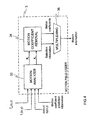
- FIG. 6 shows a mobile station MS according to an embodiment of the invention.
- a central processing unit, microprocessor ⁇ P controls the blocks responsible for different functions of the mobile station: a random access memory RAM, a radio frequency block RF, a read only memory ROM, a user interface Ul having a display DPL and a keyboard KBD, and a digital camera block CAM.
- the microprocessor's operating instructions, that is program code and the mobile station's basic functions have been stored in the mobile station in advance, for example during the manufacturing process, in the ROM.
- the microprocessor uses the RF block for transmitting and receiving messages on a radio path.
- the microprocessor monitors the state of the user interface UI and controls the digital camera block CAM.
- the microprocessor instructs the camera block CAM to record a digital image into the RAM.
- the microprocessor segments the image into Image segments and computes motion field models for the segments in order to generate a compressed image as explained in the foregoing description.
- a user may command the mobile station to display the image on its display or to send the compressed image using the RF block to another mobile station, wired telephone, facsimile device or another telecommunications device.
- such transmission of image is started as soon as the first segment is encoded so that the recipient can start decoding process with a minimum delay.
- the mobile station comprises an encoder block ENC dedicated for encoding and possibly also for decoding of digital video data.
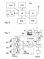
- FIG. 7 is a schematic diagram of a mobile telecommunications network according to an embodiment of the invention.
- Mobile stations MS are in communication with base stations BTS by means of a radio link.
- the base stations BTS are further connected, through a so-called Abis interface, to a base station controller BSC, which controls and manages several base stations.
- the entity formed by a number of base stations BTS (typically, by a few dozen base stations) and a single base station controller BSC, controlling the base stations, is called a base station system BSS.
- the base station controller BSC manages radio communication channels and handovers.
- the base station controller BSC is connected, through a so-called A interface, to a mobile services switching centre MSC, which co-ordinates the formation of connections both from and to mobile stations.
- a further connection is made, through the mobile service switching centre MSC, to outside the mobile communications network.
- Outside the mobile communications network there may further reside other network(s) connected to the mobile communications network by gateway(s) GTW, for example the internet.
- gateway(s) GTW for example the internet.
- the mobile telecommunications network comprises a video server VSRVR to provide video data to a MS subscribing to such a service. This video data is compressed by using the motion compensated video compression method as described earlier in this document.
- the video server may function as a gateway to an online video source or it may comprise previously recorded video dips.
Abstract
Description
- The present invention relates to video compression. In particular, the invention relates to coding of an estimated motion field and to generating motion information in a video sequence.
- Motion compensated prediction is a key element of the majority of video coding schemes. To describe the operation of motion compensated prediction it should be appreciated that each digital image contains certain set of pixels corresponding to certain parts of the image. Each pixel may be represented, for example, as intensities of Red, Green and Blue (RGB color system) or as intensities of the luminance and two chrominance components.
- Figure 1 shows illustratively two segments of an image, Sk and Sl, each showing a set of
pixels 10 to 15 at old locations, that is in a previous image of a sequence of images. The new locations of these pixels in a current image are shown as positions 10' to 15'. The change of their location, that is their motion, defines respective motion vectors v1 k to v3 k and v1 l v3 l of the pixels in these segments. At the simplest, the segments are squares or rectangles. Alternatively, and in legacy schemes, they may also be of an arbitrary form, as shown in Figure 1. - Figure 2 is a schematic diagram of an encoder for compression of video sequences using motion compensation. Essential elements in the encoder are a motion compensated
prediction block 1, a motionfield estimation block 2 and amotion field coder 3. The operating principle of motion compensating video coders is to compress the prediction error En(x, y), which is a difference between the incoming frame In(x, y) being coded, called the current frame, and a prediction frame În (x,y), wherein:prediction block 1 and is built using pixel values of the previous, or some other already coded frame denotedref (x,y), called a reference frame, and the motion vectors of pixels between the current frame and the reference frame. Motion vectors are calculated by the motion
field estimation block 2 and the resulting vector field is then coded in some way before being provided as an input to theprediction block 1. The prediction frame is then: x(x,y) and
- In the decoder, shown in Fig. 3, the current output frame
prediction block 21 generates the prediction frame using the received motion information and the reference frameprediction error decoder 22 generates the decoded prediction error Ên (x,y) for adding to the prediction frame, the result being the current output frame - The general object of motion compensated (MC) prediction is to minimize amount of information which needs to be transmitted to the decoder together with the amount of prediction error measured, e.g., as the energy of En(x, y).
- The document H. Nguen, E. Dubois, "Representation of motion information for image coding". Proc. Picture Coding Symposium '90, Cambridge, Massachusetts, March 26-18, 1990, pages 841-845, gives a review of motion field coding techniques. As a rule of thumb, reduction of prediction error requires a more sophisticated motion field model, that is, more bits must be used for its encoding. Therefore, the overall goal of video encoding is to encode the motion vector field as compactly as possible while keeping the measure of prediction error as low as possible.
- The motion
field estimation block 2, shown in Fig. 2, calculates motion vectors of all the pixels of a given image segment minimizing some measure of prediction error in this segment, for example square prediction error. - Due to the very large number of pixels in the frame, it is not efficient to transmit a separate motion vector for each pixel. Instead, in most video coding schemes, the current frame is divided into larger image segments so that all motion vectors of the segment can be described by few parameters. Image segments may be square blocks, for example, 16x16 and 8x8 pixel blocks are used in codecs in accordance with international standards ISO/IEC MPEG-1, MPEG-2, MPEG-4 or ITU-T H.261 and H.263, or they may comprise arbitrarily shaped regions obtained for instance by a segmentation algorithm. In practice, segments include at least few tens of pixels.
- In order to compactly represent the motion vectors of the pixels in a segment, it is desirable that the motion vectors are described by a function of few parameters. Such a function is called a motion vector field model. A known group of models is linear motion model, in which motion vectors are represented by linear combinations of motion field basis functions. In such models, the motion vectors of image segments are described by a general formula:where parameters ci are called motion coefficients and are transmitted to the decoder. In general, the motion model for a segment is based on N+M motion coefficients. Functions fi(x, y) are called motion field basis functions which and are known both to the encoder and decoder. Known motion field estimation techniques vary both in terms of the model used to represent the motion field and in the algorithm for minimization of a chosen measure of the prediction error.

- Both the amount and the complexity of the motion varies between frames and between segments. In one case some of the content of the image may be rotated, skewed and shifted from one side of the image to the opposite side of the image. On the other hand, in another case a video camera may turn slowly about its vertical axis so that all the pixels move slightly in horizontal plane. Therefore, it is not efficient to always use all N+M motion coefficients per segment
- One way to reduce motion Information is simply to reduce the number of motion coefficients from the motion field model that models the motion of pixels' locations from one image to another. However, the prediction error tends to increases, as the motion field model becomes coarser.
- For every segment, it is necessary to determine the minimum number of motion coefficients that yields a satisfactorily low prediction error. The process of such adaptive selection of motion coefficients is called motion coefficient removal. This process is performed in the encoder by the motion
field coding block 3, see Fig. 2. It is performed after motion field estimation performed by the motionfield estimation block 2. - In future, digital video transmission will be possible between wireless mobile terminals. Usually such terminals have limited space for additional components and operate by a battery so that they are likely not accommodate computing capacity comparable to fixed devices such as desktop computers. Therefore, it is crucial that the motion field coding performed in a video coder is computationally simple so that it does not impose an excessive burden on the processor of the device. Additionally, the encoded motion field model should be computationally simple to facilitate later decoding at a decoder In a receiving (mobile) terminal.
- Methods for performing motion estimation with different models and selecting the most suitable one are proposed in the documents H. Nicolas and C. Labit, "Region-based motion estimation using deterministic relaxation schemes for image sequence coding," Proc. 1994 International Conference on Acoustics, Speech and Signal Processing, pp. III265-268 and P. Cicconi and H. Nicolas, "Efficient region-based motion estimation and symmetry oriented segmentation for image sequence coding," IEEE Tran. on Circuits and Systems for Video Technology, Vol. 4, No. 3, June 1994, pp. 357-364. The methods attempt to adapt the motion model depending on the complexity of the motion by performing motion estimation with different models and selecting the most suitable one. The main disadvantage of these methods is their high computational complexity and the small number of different motion field models that can be tested in practice.
- Yet another method is described in WO97/16025. A video codec includes a motion field coder for minimizing the number of motion coefficients of a motion vector field. In the coder, a first block includes means for forming a new matrix representation of the motion vector field. The new coded motion vector field is linear. A second main block includes means for merging pairs of adjacent segments if the combined segment area can be predicted using a common motion field. Merging information is transmitted to a decoder. A third main block includes means for removing motion field basis functions. After each removing step, the squared prediction error is calculated and removing is continued until the magnitude of the error is not acceptable. Final motion coefficients are calculated by solving a linear matrix equation. As a result, reduced number of motion coefficients for each segment is obtained. The motion coefficients are transmitted to the decoder. This approach allows removal of motion coefficients until a certain threshold of prediction error is reached.
- However, there is still a need to further reduce the complexity of the motion encoding process as well as the amount of motion information that needs to be sent to the decoder while causing minimal deterioration in the quality of a decoded image.
- An objective of the present invention is to reduce the amount of motion information by a large factor without large increase in reconstruction error.
- Another objective is to keep the complexity of the motion field coder low to allow practical implementation using available signal processors or general-purpose microprocessors.
- The invention is defined by the appended claims.
- By taking advantage of the predicted motion coefficients in a Motion Analyzer that forms part of the motion field coder of a video encoder, a better rate-distortion performance is achieved than with prior known solutions.
- Furthermore, a motion coefficient removal block can be used to compute a plurality of alternate combinations of motion coefficients to be used for further optimization of the rate-distortion performance. Preferably, the motion coefficient removal block is adapted to implement certain cost function to find a combination with which the ultimate rate-distortion will be optimized.
-
- Fig. I is a schematic diagram of an image divided in segments;
- Fig. 2 is a schematic diagram of an encoder according to prior art;
- Fig. 3 is a schematic diagram of a decoder according to prior art;
- Fig. 4 is a Motion Field Coder according to an embodiment of the invention;
- Fig. 5 is a Motion Analyzer according to an embodiment of the invention;
- Fig. 6 is a schematic diagram of a mobile station according to an embodiment of the invention;
- Fig. 7 is a schematic diagram of a mobile telecommunications network according to an embodiment of the invention.
-
- Figures 1 to 3 are described above.
- In the following, an overview of the invention is provided to facilitate the further description of various embodiments of the invention.
- In accordance with a preferred embodiment of the invention, the motion field coder of a video encoder comprises two main blocks.
- The first main block is called a
Motion Analyzer 32, Figures 4 and 5. Its task is to find a new representation of the inputted motion field produced by the motionfield estimation block 2, Figure 2. This new representation is applied to the second main block, a motioncoefficient removal block 34, Figure 4. Operations in the Motion Analyzer include a plurality of steps comprising matrix operations: In the first step the prediction frame's dependency on motion vectors is linearized using an approximation method. In the second step, a matrix Ak and a vector dk are constructed for minimization of the square prediction error. In the third step, a diagonal system of linear equations based on factorization of Ak is built in order to create a flexible motion representation in the form of a diagonal matrix Rk and an auxiliary vector zk. - The Motion
Coefficient Removal block 34 inputs the diagonal matrix Rk and the auxiliary vector zk produced by the Motion Analyzer block. Motion vectors of a segment are represented by a number of motion coefficients. For each of the segments, the motion coefficient removal block determines if it is possible to simplify the motion field model without causing an excessive increase in reconstruction error. Typically, some basis functions are removed from the motion model, whereby fewer coefficients are required to describe such a simplified motion field model. - The Motion
Coefficient Removal block 34 modifies matrix equations involving the diagonal matrix R k by removing one column of the diagonal matrix R k and triangularizing the new system. As a result, there is one motion coefficient less in the equations and one term is removed from the vector z k. This operation corresponds to removal of one basis function from the motion field model. In order to determine a motion field model which optimizes a selected prediction error measure, or cost function, these operations are repeated until there are no basis functions remaining in the motion field model. Every time a basis function is removed, a new set of motion coefficients is evaluated by solving the matrix equations. This may be done by using any of the well known algorithms, for example, backsubstitution. The final set of motion parameters, i.e. chosen to represent the motion of a particular segment, is the one minimizing the cost function. Preferably, the cost function is a weighted sum of a measure of prediction error and a measure of information required for decoding the image. - For every processed segment, the Motion
Coefficient Removal block 34 outputs selection information that defines the basis functions removed from the motion field model. Additionally, it outputs new motion coefficients corresponding to the remaining basis functions. Both the selection information and the new motion coefficients are transmitted to the decoder. - Fig. 4 illustrates a
motion field encoder 3 according to an embodiment of the invention. It corresponds to theblock 3 in Fig. 2. It inputs the reference frameField Estimation block 2, Fig. 2. - The output of the video encoder contains a compressed frame divided into segments defined by motion coefficients for a segment Sk, which consists of P pixels with coordinates (xi, yi), i = 1,2,...P. The task of the Motion Field Coder is to find the motion coefficients=(


- Where the distortion D(Sk) is the square error between the original and the coded segment. The rate R(Sk) is equal to the number of bits needed to code the segment and parameter λ is a predefined coefficient defining the trade-off between the quality of the coded segment and the number of bits required for the compression of the segment.
- To fulfill this task, the
Motion Field Coder 3 comprises two main blocks, which are theMotion Analyzer block 32 and the MotionCoefficient Removal block 34. The objective of theMotion Analyzer 32 is to find a new representation of the motion field. This new representation is used later, in the MotionCoefficient Removal block 34, to find motion coefficients for a given image segment in a fast and flexible manner. The MotionCoefficient Removal block 34 reduces the amount of motion information used to describe the motion field of a segment, which results in increase of the square prediction error, defined as
- The operation of the
Motion Analyzer 32 is next described in detail referring to Figure 5. The operation of theMotion Analyzer 32 comprises the following steps: - Step 1: Linearization of the error, block 42. In this step the reference
frame

- Step 2: Construction of matrices, block 43. Minimization of formula (7) is
fully equivalent to minimization of the matrix expression (E k c k- yk)T(E k c k - y k) or
solving the following equation:
block 46.
- Step 3: Triangularization and creation of output, block 44. In this step
equation (8) is triangularized using a known method to decompose A k into a
product of a lower diagonal matrix R k T and its transpose R k
-
- This may be carried out using Cholesky decomposition.
- An auxiliary vector z k 0 is created solving
- The motion coefficients c k can be given as sums of predicted motion coefficients p k and refinement motion coefficients r k. The predicted motion coefficients are predicted from previously generated motion coefficients and the refinement motion coefficients correspond to the difference between the predicted motion coefficients and motion coefficients calculated in the Motion Field estimation block (Figure 2). In this case, equation (12) has the form:
p Block 47 forms the term z k 0 and block 45 generates the term R k p k. The output of the following MotionCoefficient Removal block 34 becomes refinement motion coefficients instead of absolute motion coefficients. Otherwise output vector z k = z k 0. - Motion
Coefficient Removal block 34 receives as input matrix R k and vector z k produced by theMotion Analyzer block 32. Motion vectors of every segment are represented by N+M motion coefficients. - For a given segment Sk, the Motion Coefficient Removal block determines if it is possible to simplify the motion field model, without excessively Increasing the selected error measure. A simplified motion field model is obtained when some basis functions are removed from the model in equations (3) described in the background art of this application. Fewer coefficients are required to describe such a simplified motion field model.
- The following iterative procedure is performed in order to find the optimal motion vector field.
- Step A: Initial cost calculation. A Lagrangian cost for the segment is evaluated with the full motion model and stored together with the full set of motion coefficients.
- Step B: Finding the basis function with the smallest impact on prediction quality. Let R k n denote an n x n upper diagonal characteristic matrix with n basis functions remaining and R k n,i the same matrix with the i'th column removed. n sets of equations are generated each with the i'th column removed from the matrix R k n and the i'th element removed form the vector c k n :
- All the equations generated are triangularized in a known manner by applying a series of multiplications of rows by scalars followed by additions of the rows, i.e., equation (15) is converted to the form:

- Where (qi)2 is an approximation of the increase in the square prediction error due to removing the i'th basis function from the motion model. The column yielding the smallest (qi)2 when removed is the one to be removed during this iteration, effectively causing the i'th basis function to be removed from the motion model.
- Step C: Removing a basis function from the model. A new matrix equation is built by selecting matrix R k n,i and vector z k n,i associated with the basis function to be removed and removing the last row of the matrix and the last element of the vector as follows:

- Step D: Coefficient calculation. A new set of motion coefficients for the reduced set of basis functions is calculated by solving the triangular system:
- Step E: Cost calculation. A Lagrangian cost for the segment is evaluated and stored together with the set of motion parameters if this model is the best one so far.
- Step F: Final motion model selection. If there are still basis functions to be removed, steps B to E are repeated. If all the basis functions have been removed from the model, the output is generated. The output comprises selection information, describing which basis functions should be removed from motion field model, together with new motion coefficients corresponding to the remaining basis functions. Both selection information and motion coefficients are transmitted to the decoder.
- The main advantage of the present invention over prior art solutions is its ability to reduce the amount of motion information by a large factor without causing a large increase in reconstruction error. Additionally, the complexity of the overall system is low which allows practical implementation on available signal processors or general-purpose microprocessors.
- The Motion Coefficient Removal block is a very powerful tool for instantaneous adaptation of the motion model to the actual amount and type of motion in the video scene. This block can be used to test a large number of motion models, with or without motion parameter prediction. A strong advantage of this scheme is that it does not need to repeat the process of motion estimation when changing motion model and hence it is computationally simple.
- By using motion estimation followed by Motion Analyzer the motion field coder can find new motion coefficients for any desired model of the motion field by solving computationally a very simple systems of linear equations.
- In the preferred embodiment, an orthonormalized affine motion vector field model with 6 coefficients is used. In practice, this model can handle with a high degree of accuracy even very complex motion in video sequences and yields good prediction results.
- The affine motion vector field is a motion model that can be used to approximate motion vectors with a set of motion coefficients. The affine motion model allows description of various types of motion, including translational, rotational, zooming and skewing movements. It comprises 6 basis functions, in which case, the motion vectors may be substantially replaced by a sum involving six basis functions multiplied by motion coefficients, each motion coefficient computed for one particular basis function. The basis functions themselves are known to both the encoder and decoder.
- In the
Motion Analyzer block 32, linearization instep 1 is performed using Taylor expansion of the reference frame
- Using the property thata 2 =


- Auxiliary values gj(x, y) are calculated using the formula:where functions fj(xi,yi) are basis function as defined in equation (4). Matrix E k and vector y k in equation (9) are built using formulae:


- Gx(x, y) and Gy(x, y) are values of the horizontal and vertical gradient of the reference frame
- Matrix A k is factorized using Cholesky decomposition and the system in formula (15) is triangularized using a sequence of Givens rotations.
- Motion coefficients for new motion models are calculated by solving equation (18) using a backsubstitution algorithm.
- The pixel values of
- Figure 6 shows a mobile station MS according to an embodiment of the invention. A central processing unit, microprocessor µP controls the blocks responsible for different functions of the mobile station: a random access memory RAM, a radio frequency block RF, a read only memory ROM, a user interface Ul having a display DPL and a keyboard KBD, and a digital camera block CAM. The microprocessor's operating instructions, that is program code and the mobile station's basic functions have been stored in the mobile station in advance, for example during the manufacturing process, in the ROM. In accordance with its program, the microprocessor uses the RF block for transmitting and receiving messages on a radio path. The microprocessor monitors the state of the user interface UI and controls the digital camera block CAM. In response to a user command, the microprocessor instructs the camera block CAM to record a digital image into the RAM. Once the image is captured or alternatively during the capturing process, the microprocessor segments the image into Image segments and computes motion field models for the segments in order to generate a compressed image as explained in the foregoing description. A user may command the mobile station to display the image on its display or to send the compressed image using the RF block to another mobile station, wired telephone, facsimile device or another telecommunications device. In a preferred embodiment, such transmission of image is started as soon as the first segment is encoded so that the recipient can start decoding process with a minimum delay. In an alternative embodiment, the mobile station comprises an encoder block ENC dedicated for encoding and possibly also for decoding of digital video data.
- Figure 7 is a schematic diagram of a mobile telecommunications network according to an embodiment of the invention. Mobile stations MS are in communication with base stations BTS by means of a radio link. The base stations BTS are further connected, through a so-called Abis interface, to a base station controller BSC, which controls and manages several base stations. The entity formed by a number of base stations BTS (typically, by a few dozen base stations) and a single base station controller BSC, controlling the base stations, is called a base station system BSS. Particularly, the base station controller BSC manages radio communication channels and handovers. On the other hand, the base station controller BSC is connected, through a so-called A interface, to a mobile services switching centre MSC, which co-ordinates the formation of connections both from and to mobile stations. A further connection is made, through the mobile service switching centre MSC, to outside the mobile communications network. Outside the mobile communications network there may further reside other network(s) connected to the mobile communications network by gateway(s) GTW, for example the internet. In such external network, or in the telecommunications network, there may be located another video decoding or encoding stations, such as computers PC. In an embodiment of the invention, the mobile telecommunications network comprises a video server VSRVR to provide video data to a MS subscribing to such a service. This video data is compressed by using the motion compensated video compression method as described earlier in this document. The video server may function as a gateway to an online video source or it may comprise previously recorded video dips.
- The system can be implemented in a variety of ways without departing from the spirit and scope of the invention. For instance:
- Different motion models can be used.
- Different cost functions can be used instead of the Lagrangian cost given in equation (5).
- Different methods can be used to linearize the term in formula (6).
- Different factorization algorithms can be used in the Motion Analyzer (e.g. QR decomposition instead of Cholesky decomposition).
- The strategy for deciding the removal order of basis functions may vary (e.g. a predefined order can be used instead of evaluating qi's in equation (16)).
- Some motion models can be skipped in the Motion Coefficient Removal block (e.g. if some input coefficients have negligible amplitude, algorithm may decide to discard corresponding basis functions).
- Cost calculation in the Motion Coefficient Removal block does not have to take place immediately after removal of a basis function but can be delayed. This means that in the Coefficient Removal block Steps B-D may be iterated instead of steps B-E. Step E (cost calculation) can then be performed in another loop for all the generated motion models (for this segment).
- Triangularization of the system in equation (15) can be performed using various algorithms.
- Calculation of final coefficients by solving equation (18) can be performed using a number of known algorithms for solving systems of linear equations.
- Prediction terms in equations (13) and (14) can be incorporated alternatively by substituting motion vectors (Δx(xi, yi) and Δy(xi, yi)) in equation (23) by motion vector refinements (differences between estimated motion vectors and predicted motion vectors).
- Different interpolation methods can be used to obtain values of
Claims (20)
- A video encoder for motion compensated encoding of video data comprising:characterised in that the video encoder further comprises:means for generating a first motion vector for a first image segment Sk of a current frame to be encoded based on a reference frame;a motion field encoder for encoding the first motion vector to provide compressed motion information comprising a first motion coefficient vector c k comprising a set of absolute motion coefficients ci, such that ci · fi(x,y) represents an approximation of the first motion vector, fi (x,y) defines a set of basis functions and i is an index defining correspondences between particular basis functions and absolute motion coefficients ci;means for generating a second motion vector for a second image segment SI of the current frame to be subsequently encoded based on the reference frame;means for encoding the second motion vector to provide compressed motion information comprising a second motion coefficient vector c l comprising a second set of absolute motion coefficients c j, such that c j · fj(x,y) represents an approximation of the second motion vector for the second image segment SI, fj (x,y) defines a set of basis functions and j is an index defining correspondences between particular basis functions and absolute motion coefficients cj; andmeans for predicting a predicted motion coefficient vector p l for the second image segment Sl, comprising a set of predicted motion coefficients pj, based upon the previously generated first motion coefficient vector c k ;means for representing each of the absolute motion coefficients cj of the second set of absolute motion coefficients as a sum of a corresponding predicted motion coefficient pj and refinement motion coefficient rj, where each of the refinement motion coefficients r j represents the difference between one of the absolute motion coefficients c j and the corresponding predicted motion coefficient pj;means for determining values for the refinement motion coefficients r j; andmeans for representing the second motion coefficient vector c l for the second image segment Sl as a vector of refinement motion coefficients rj.
- A video encoder according to claim 1, characterised in that each of the motion vectors is represented by an affine motion model.
- A video encoder according to claim 1 or 2, characterised in that the absolute motion coefficients, the refinement motion coefficients, and the predicted motion coefficients together with the corresponding basis functions represent an affine motion model.
- A video encoder according to any of the preceding claims, characterised in that the encoder further comprises:means for computing a first cost (L(St)) representing a first amount of image distortion and a first amount of information necessary to represent the segment Sl with the first amount of distortion and corresponding to a first selection of motion coefficients;means for computing a second cost (L(Sl)) representing a second amount of image distortion and a second amount of information necessary to represent the segment Sl with the second amount of distortion and corresponding to a second selection of motion coefficients, the second selection differing from the first selection;means for choosing among the first and second cost that which is closer to but does not exceed a predetermined maximum cost; andmeans for calculating motion coefficients cj corresponding to the chosen cost.
- A video encoder according to any of the preceding claims, characterised in that the encoder further comprises:means for calculating a matrix El and a vector yl for the second image segment Sl;means for calculating a predefined distortion measure for the second segment as a function of EIcI-yI, cl being the second motion vector comprising the second set of absolute motion coefficients cj; andmeans for generating a diagonal matrix R I and a corresponding vector z I 0 from the matrix E I and a vector y I.
- A video encoder according to claim 5, characterised in that it further comprises means for obtaining matrix R I by decomposing matrix A I = E I T E I into a lower diagonal matrix R I T and its transpose R I so that A i = R T l R l .
- A video encoder according to claim 5 or 6, characterised in that it further comprises means for obtaining vector z I 0 by calculating d I = E I T y I and solving the set of equations R T l z 0 l = d l .
- A video encoder according to any of claims 5 to 7, characterised in that it further comprises means for calculating an output vector z l = z 0 l - R l p l .
- A storage device comprising a video encoder according to any of claims 1 to 8.
- A mobile station comprising a video encoder according to any of claims 1 to 8.
- A mobile telecommunications network comprising a video encoder according to any of claims 1 to 8.
- A computer program product comprising a video encoder according to any of claims 1 to 8.
- A method for motion compensated encoding of video data comprising the steps of:characterised in that the method further comprises:generating a first motion vector for a first image segment Sk of a current frame to be encoded based on a reference frame;encoding the first motion vector to provide compressed motion information comprising a first motion coefficient vector c k comprising a first set of absolute motion coefficients ci, such that ci · fi (x,y) represents an approximation of the first motion vector, fi (x,y) defines a set of basis functions and i is an index defining correspondences between particular basis functions and absolute motion coefficients ci;generating a second motion vector for a second image segment SI of the current frame to be subsequently encoded based on the reference frame;encoding the second motion vector to provide compressed motion information comprising a second motion coefficient vector c I comprising a second set of absolute motion coefficients c j, such that c j · f j(x,y) represents an approximation of the second motion vector for the second image segment SI, fj (x,y) defines a set of basis functions and j is an index defining correspondences between particular basis functions and absolute motion coefficients cj; andpredicting a predicted motion coefficient vector p l for the second image segment Sl, comprising a set of predicted motion coefficients pj, based upon the first motion coefficient vector c k;representing each of the absolute motion coefficients cj of the second set of absolute motion coefficients as a sum of a corresponding predicted motion coefficient pj and refinement motion coefficient rj, where each of the refinement motion coefficients rj represents a difference between one of the absolute motion coefficients cj and a corresponding predicted motion coefficient pj;determining values for the refinement motion coefficients rj; andrepresenting the second motion coefficient vector c l as a vector of refinement motion coefficients rj.
- A method according to claim 13, characterised in that each of the motion vectors is represented by an affine motion model.
- A method according to claim 13 or 14, characterised in that the absolute motion coefficients, the refinement motion coefficients, and the predicted motion coefficients together with the corresponding basis functions represent an affine motion model.
- A method according to any of claims 13 to 15, characterised in that the method further comprises the steps of:computing a first cost (L(Sl )) representing a first amount of image distortion and a first amount of information necessary to represent the segment SI with the first amount of distortion and corresponding to a first selection of motion coefficients;computing a second cost (L(Sl)) representing a second amount of image distortion and a second amount of information necessary to represent the segment SI with the second amount of distortion and corresponding to a second selection of motion coefficients, the second selection differing from the first selection;choosing among the first and second cost that which is closer to but does not exceed a predetermined maximum cost; andcalculating motion coefficients c j corresponding to the chosen cost.
- A method according to any of claims 13 to 16, characterised in that the method further comprises the steps of:calculating a matrix E I and a vector y I for the second image segment SI;calculating a predefined distortion measure for the second segment SI as a function of E I c I -y I , c I being the second motion vector comprising the second set of absolute motion coefficients c l; andgenerating a diagonal matrix R I and a corresponding vector z I 0 from the matrix E I and a vector y I .
- A method according to claim 17, characterised in that the method further comprises the step of obtaining matrix R I by decomposing matrix A I = E I T E I into a lower diagonal matrix R I T and its transpose R I so that A l = R T l R l .
- A method according to claim 17 or 18, characterised in that the method further comprises the step of obtaining vector z I 0 by calculating d I = E I T y I and solving the set of equations R T l z0 l = d l .
- A method according to any of claims 17 to 19, characterised in that the method further comprises the step of:calculating an output vector z l = z 0 l -R l p l .
Applications Claiming Priority (5)
| Application Number | Priority Date | Filing Date | Title |
|---|---|---|---|
| US489327 | 1983-04-28 | ||
| US09/371,641 US6735249B1 (en) | 1999-08-11 | 1999-08-11 | Apparatus, and associated method, for forming a compressed motion vector field utilizing predictive motion coding |
| US371641 | 1999-08-11 | ||
| US09/489,327 US6711209B1 (en) | 1999-08-11 | 2000-01-21 | Adaptive motion vector field coding |
| PCT/US2000/021824 WO2001011892A1 (en) | 1999-08-11 | 2000-08-10 | Adaptive motion vector field coding |
Publications (2)
| Publication Number | Publication Date |
|---|---|
| EP1228645A1 EP1228645A1 (en) | 2002-08-07 |
| EP1228645B1 true EP1228645B1 (en) | 2003-05-28 |
Family
ID=27005456
Family Applications (1)
| Application Number | Title | Priority Date | Filing Date |
|---|---|---|---|
| EP00955421A Expired - Lifetime EP1228645B1 (en) | 1999-08-11 | 2000-08-10 | Adaptive motion vector field coding |
Country Status (7)
| Country | Link |
|---|---|
| US (1) | US7161983B2 (en) |
| EP (1) | EP1228645B1 (en) |
| JP (1) | JP4596718B2 (en) |
| CN (1) | CN1229997C (en) |
| AT (1) | ATE241887T1 (en) |
| DE (1) | DE60003070T2 (en) |
| WO (1) | WO2001011892A1 (en) |
Families Citing this family (39)
| Publication number | Priority date | Publication date | Assignee | Title |
|---|---|---|---|---|
| US6735249B1 (en) * | 1999-08-11 | 2004-05-11 | Nokia Corporation | Apparatus, and associated method, for forming a compressed motion vector field utilizing predictive motion coding |
| US6530329B2 (en) * | 2001-05-15 | 2003-03-11 | Matthew A. Katzer | Model train control system |
| GB2374479B (en) * | 2001-04-12 | 2005-05-04 | Snell & Wilcox Ltd | Video signal processing |
| US20060100753A1 (en) * | 2004-11-10 | 2006-05-11 | Katzer Matthew A | Model train control |
| CN100393133C (en) * | 2004-12-30 | 2008-06-04 | 中兴通讯股份有限公司 | Method for segmenting mobile in video sequence |
| KR100746022B1 (en) * | 2005-06-14 | 2007-08-06 | 삼성전자주식회사 | Method and apparatus for encoding video signal with improved compression efficiency using model switching of sub pixel's motion estimation |
| US7944965B2 (en) * | 2005-12-19 | 2011-05-17 | Seiko Epson Corporation | Transform domain based distortion cost estimation |
| KR100939917B1 (en) | 2008-03-07 | 2010-02-03 | 에스케이 텔레콤주식회사 | Encoding system using motion estimation and encoding method using motion estimation |
| US8107750B2 (en) * | 2008-12-31 | 2012-01-31 | Stmicroelectronics S.R.L. | Method of generating motion vectors of images of a video sequence |
| US8254443B2 (en) * | 2009-08-28 | 2012-08-28 | Ericsson Television, Inc. | Latency rate distortion optimisation |
| TWI498008B (en) * | 2009-12-30 | 2015-08-21 | Altek Corp | Method of Adjusting Camera Parameters of Whole - week Images |
| JP5441803B2 (en) * | 2010-04-12 | 2014-03-12 | キヤノン株式会社 | Motion vector determination device, motion vector determination method, and computer program |
| EP2490448A1 (en) * | 2011-02-18 | 2012-08-22 | Siemens Aktiengesellschaft | Encoding method and image encoding device for compressing an image sequence |
| US8644383B2 (en) * | 2011-03-10 | 2014-02-04 | Microsoft Corporation | Mean absolute difference prediction for video encoding rate control |
| US8891626B1 (en) * | 2011-04-05 | 2014-11-18 | Google Inc. | Center of motion for encoding motion fields |
| KR20140034292A (en) | 2011-07-01 | 2014-03-19 | 모토로라 모빌리티 엘엘씨 | Motion vector prediction design simplification |
| US20130083845A1 (en) | 2011-09-30 | 2013-04-04 | Research In Motion Limited | Methods and devices for data compression using a non-uniform reconstruction space |
| WO2013067440A1 (en) | 2011-11-04 | 2013-05-10 | General Instrument Corporation | Motion vector scaling for non-uniform motion vector grid |
| EP2595382B1 (en) | 2011-11-21 | 2019-01-09 | BlackBerry Limited | Methods and devices for encoding and decoding transform domain filters |
| US8908767B1 (en) | 2012-02-09 | 2014-12-09 | Google Inc. | Temporal motion vector prediction |
| ITVI20120087A1 (en) | 2012-04-17 | 2013-10-18 | St Microelectronics Srl | DIGITAL VIDEO STABILIZATION |
| US9172970B1 (en) | 2012-05-29 | 2015-10-27 | Google Inc. | Inter frame candidate selection for a video encoder |
| US11317101B2 (en) | 2012-06-12 | 2022-04-26 | Google Inc. | Inter frame candidate selection for a video encoder |
| US9485515B2 (en) | 2013-08-23 | 2016-11-01 | Google Inc. | Video coding using reference motion vectors |
| US9503746B2 (en) | 2012-10-08 | 2016-11-22 | Google Inc. | Determine reference motion vectors |
| US20140169444A1 (en) * | 2012-12-14 | 2014-06-19 | Microsoft Corporation | Image sequence encoding/decoding using motion fields |
| EP2997732A1 (en) * | 2013-05-15 | 2016-03-23 | VID SCALE, Inc. | Single loop decoding based inter layer prediction |
| US9313493B1 (en) | 2013-06-27 | 2016-04-12 | Google Inc. | Advanced motion estimation |
| JP6636615B2 (en) * | 2015-08-24 | 2020-01-29 | ホアウェイ・テクノロジーズ・カンパニー・リミテッド | Motion vector field encoding method, decoding method, encoding device, and decoding device |
| US10063872B2 (en) | 2015-09-11 | 2018-08-28 | Facebook, Inc. | Segment based encoding of video |
| US10506235B2 (en) | 2015-09-11 | 2019-12-10 | Facebook, Inc. | Distributed control of video encoding speeds |
| US10602153B2 (en) | 2015-09-11 | 2020-03-24 | Facebook, Inc. | Ultra-high video compression |
| US10602157B2 (en) | 2015-09-11 | 2020-03-24 | Facebook, Inc. | Variable bitrate control for distributed video encoding |
| US10341561B2 (en) * | 2015-09-11 | 2019-07-02 | Facebook, Inc. | Distributed image stabilization |
| US10375156B2 (en) | 2015-09-11 | 2019-08-06 | Facebook, Inc. | Using worker nodes in a distributed video encoding system |
| US10499070B2 (en) | 2015-09-11 | 2019-12-03 | Facebook, Inc. | Key frame placement for distributed video encoding |
| EP3362160B1 (en) * | 2015-10-16 | 2020-04-22 | Anthony J. Ireland | Overlay speed improvements for a layout control system |
| JP6669617B2 (en) * | 2016-09-12 | 2020-03-18 | ルネサスエレクトロニクス株式会社 | Video processing system |
| WO2018209067A1 (en) * | 2017-05-11 | 2018-11-15 | Vid Scale, Inc. | Higher-order motion models and graduated motion parameter estimation for video coding |
Family Cites Families (10)
| Publication number | Priority date | Publication date | Assignee | Title |
|---|---|---|---|---|
| SE469866B (en) * | 1991-04-12 | 1993-09-27 | Dv Sweden Ab | Method for estimating motion content in video signals |
| US5594504A (en) | 1994-07-06 | 1997-01-14 | Lucent Technologies Inc. | Predictive video coding using a motion vector updating routine |
| JP3781194B2 (en) * | 1995-10-20 | 2006-05-31 | ノキア コーポレイション | Motion vector field coding |
| US5778192A (en) * | 1995-10-26 | 1998-07-07 | Motorola, Inc. | Method and device for optimal bit allocation between different sources of information in digital video compression |
| JP3790804B2 (en) * | 1996-04-19 | 2006-06-28 | ノキア コーポレイション | Video encoder and decoder using motion based segmentation and merging |
| DE69803266T2 (en) * | 1997-03-14 | 2002-08-08 | Cselt Centro Studi Lab Telecom | CIRCUIT FOR MOTION ESTIMATION IN CODERS FOR DIGITALIZED VIDEO SEQUENCES |
| JP3351705B2 (en) * | 1997-04-25 | 2002-12-03 | 日本ビクター株式会社 | Motion compensation coding apparatus, motion compensation coding method, and recording method on recording medium |
| JP4573366B2 (en) * | 1997-09-25 | 2010-11-04 | 株式会社大宇エレクトロニクス | Motion vector coding method and coding apparatus |
| GB2343319B (en) * | 1998-10-27 | 2003-02-26 | Nokia Mobile Phones Ltd | Video coding |
| US6418166B1 (en) * | 1998-11-30 | 2002-07-09 | Microsoft Corporation | Motion estimation and block matching pattern |
-
2000
- 2000-08-10 EP EP00955421A patent/EP1228645B1/en not_active Expired - Lifetime
- 2000-08-10 CN CNB008117128A patent/CN1229997C/en not_active Expired - Fee Related
- 2000-08-10 JP JP2001515632A patent/JP4596718B2/en not_active Expired - Fee Related
- 2000-08-10 WO PCT/US2000/021824 patent/WO2001011892A1/en active IP Right Grant
- 2000-08-10 AT AT00955421T patent/ATE241887T1/en not_active IP Right Cessation
- 2000-08-10 DE DE60003070T patent/DE60003070T2/en not_active Expired - Lifetime
-
2004
- 2004-03-05 US US10/795,083 patent/US7161983B2/en not_active Expired - Fee Related
Also Published As
| Publication number | Publication date |
|---|---|
| ATE241887T1 (en) | 2003-06-15 |
| WO2001011892A9 (en) | 2001-08-16 |
| JP4596718B2 (en) | 2010-12-15 |
| EP1228645A1 (en) | 2002-08-07 |
| US20040258155A1 (en) | 2004-12-23 |
| DE60003070D1 (en) | 2003-07-03 |
| US7161983B2 (en) | 2007-01-09 |
| JP2003532309A (en) | 2003-10-28 |
| CN1370376A (en) | 2002-09-18 |
| CN1229997C (en) | 2005-11-30 |
| DE60003070T2 (en) | 2004-04-01 |
| WO2001011892A1 (en) | 2001-02-15 |
Similar Documents
| Publication | Publication Date | Title |
|---|---|---|
| EP1228645B1 (en) | Adaptive motion vector field coding | |
| US6711209B1 (en) | Adaptive motion vector field coding | |
| US6954502B2 (en) | Method for encoding and decoding video information, a motion compensated video encoder and a corresponding decoder | |
| EP1404135B1 (en) | A motion estimation method and a system for a video coder | |
| JP2003532309A6 (en) | Adaptive motion vector field coding | |
| EP0705035B1 (en) | Encoding data represented as a multi-dimensional array | |
| US6560284B1 (en) | Video coder/decoder | |
| EP1274254B1 (en) | Video coding device and video decoding device with a motion compensated interframe prediction | |
| KR101228651B1 (en) | Method and apparatus for performing motion estimation | |
| US7672377B2 (en) | Method and system for video encoding and transcoding | |
| US6507617B1 (en) | Video coding | |
| EP1971153A1 (en) | Method for encoding and decoding video information, a motion compensated video encoder and a corresponding decoder | |
| EP0894403A1 (en) | Video encoder and decoder using motion-based segmentation and merging | |
| JPH0795594A (en) | Method and apparatus for detection of motion vector of half pixel accuracy | |
| JPH09261662A (en) | Method and device for estimating motion in digital video encoder | |
| EP1553781A2 (en) | Method and apparatus for processing digital motion pictures by predicting motion compensation error using previous block. | |
| Soongsathitanon et al. | A novel orthogonal logarithmic search algorithm for low-bit-rate video coding |
Legal Events
| Date | Code | Title | Description |
|---|---|---|---|
| PUAI | Public reference made under article 153(3) epc to a published international application that has entered the european phase |
Free format text: ORIGINAL CODE: 0009012 |
|
| 17P | Request for examination filed |
Effective date: 20020311 |
|
| AK | Designated contracting states |
Kind code of ref document: A1 Designated state(s): AT BE CH CY DE DK ES FI FR GB GR IE IT LI LU MC NL PT SE |
|
| AX | Request for extension of the european patent |
Free format text: AL;LT;LV;MK;RO;SI |
|
| GRAH | Despatch of communication of intention to grant a patent |
Free format text: ORIGINAL CODE: EPIDOS IGRA |
|
| GRAH | Despatch of communication of intention to grant a patent |
Free format text: ORIGINAL CODE: EPIDOS IGRA |
|
| GRAA | (expected) grant |
Free format text: ORIGINAL CODE: 0009210 |
|
| AK | Designated contracting states |
Designated state(s): AT BE CH CY DE DK ES FI FR GB GR IE IT LI LU MC NL PT SE |
|
| PG25 | Lapsed in a contracting state [announced via postgrant information from national office to epo] |
Ref country code: IT Free format text: LAPSE BECAUSE OF FAILURE TO SUBMIT A TRANSLATION OF THE DESCRIPTION OR TO PAY THE FEE WITHIN THE PRESCRIBED TIME-LIMIT;WARNING: LAPSES OF ITALIAN PATENTS WITH EFFECTIVE DATE BEFORE 2007 MAY HAVE OCCURRED AT ANY TIME BEFORE 2007. THE CORRECT EFFECTIVE DATE MAY BE DIFFERENT FROM THE ONE RECORDED. Effective date: 20030528 Ref country code: CH Free format text: LAPSE BECAUSE OF FAILURE TO SUBMIT A TRANSLATION OF THE DESCRIPTION OR TO PAY THE FEE WITHIN THE PRESCRIBED TIME-LIMIT Effective date: 20030528 Ref country code: AT Free format text: LAPSE BECAUSE OF FAILURE TO SUBMIT A TRANSLATION OF THE DESCRIPTION OR TO PAY THE FEE WITHIN THE PRESCRIBED TIME-LIMIT Effective date: 20030528 Ref country code: BE Free format text: LAPSE BECAUSE OF FAILURE TO SUBMIT A TRANSLATION OF THE DESCRIPTION OR TO PAY THE FEE WITHIN THE PRESCRIBED TIME-LIMIT Effective date: 20030528 Ref country code: LI Free format text: LAPSE BECAUSE OF FAILURE TO SUBMIT A TRANSLATION OF THE DESCRIPTION OR TO PAY THE FEE WITHIN THE PRESCRIBED TIME-LIMIT Effective date: 20030528 |
|
| REG | Reference to a national code |
Ref country code: GB Ref legal event code: FG4D |
|
| REG | Reference to a national code |
Ref country code: CH Ref legal event code: EP |
|
| REG | Reference to a national code |
Ref country code: IE Ref legal event code: FG4D |
|
| REF | Corresponds to: |
Ref document number: 60003070 Country of ref document: DE Date of ref document: 20030703 Kind code of ref document: P |
|
| PG25 | Lapsed in a contracting state [announced via postgrant information from national office to epo] |
Ref country code: CY Free format text: LAPSE BECAUSE OF FAILURE TO SUBMIT A TRANSLATION OF THE DESCRIPTION OR TO PAY THE FEE WITHIN THE PRESCRIBED TIME-LIMIT Effective date: 20030810 Ref country code: LU Free format text: LAPSE BECAUSE OF NON-PAYMENT OF DUE FEES Effective date: 20030810 |
|
| PG25 | Lapsed in a contracting state [announced via postgrant information from national office to epo] |
Ref country code: IE Free format text: LAPSE BECAUSE OF NON-PAYMENT OF DUE FEES Effective date: 20030811 |
|
| PG25 | Lapsed in a contracting state [announced via postgrant information from national office to epo] |
Ref country code: PT Free format text: LAPSE BECAUSE OF FAILURE TO SUBMIT A TRANSLATION OF THE DESCRIPTION OR TO PAY THE FEE WITHIN THE PRESCRIBED TIME-LIMIT Effective date: 20030828 Ref country code: DK Free format text: LAPSE BECAUSE OF FAILURE TO SUBMIT A TRANSLATION OF THE DESCRIPTION OR TO PAY THE FEE WITHIN THE PRESCRIBED TIME-LIMIT Effective date: 20030828 Ref country code: GR Free format text: LAPSE BECAUSE OF FAILURE TO SUBMIT A TRANSLATION OF THE DESCRIPTION OR TO PAY THE FEE WITHIN THE PRESCRIBED TIME-LIMIT Effective date: 20030828 Ref country code: SE Free format text: LAPSE BECAUSE OF FAILURE TO SUBMIT A TRANSLATION OF THE DESCRIPTION OR TO PAY THE FEE WITHIN THE PRESCRIBED TIME-LIMIT Effective date: 20030828 |
|
| PG25 | Lapsed in a contracting state [announced via postgrant information from national office to epo] |
Ref country code: MC Free format text: LAPSE BECAUSE OF NON-PAYMENT OF DUE FEES Effective date: 20030831 |
|
| PG25 | Lapsed in a contracting state [announced via postgrant information from national office to epo] |
Ref country code: ES Free format text: LAPSE BECAUSE OF FAILURE TO SUBMIT A TRANSLATION OF THE DESCRIPTION OR TO PAY THE FEE WITHIN THE PRESCRIBED TIME-LIMIT Effective date: 20030908 |
|
| LTIE | Lt: invalidation of european patent or patent extension |
Effective date: 20030528 |
|
| REG | Reference to a national code |
Ref country code: CH Ref legal event code: PL |
|
| ET | Fr: translation filed | ||
| PLBE | No opposition filed within time limit |
Free format text: ORIGINAL CODE: 0009261 |
|
| STAA | Information on the status of an ep patent application or granted ep patent |
Free format text: STATUS: NO OPPOSITION FILED WITHIN TIME LIMIT |
|
| 26N | No opposition filed |
Effective date: 20040302 |
|
| REG | Reference to a national code |
Ref country code: IE Ref legal event code: MM4A |
|
| PGFP | Annual fee paid to national office [announced via postgrant information from national office to epo] |
Ref country code: FI Payment date: 20120810 Year of fee payment: 13 Ref country code: GB Payment date: 20120808 Year of fee payment: 13 |
|
| PGFP | Annual fee paid to national office [announced via postgrant information from national office to epo] |
Ref country code: FR Payment date: 20120823 Year of fee payment: 13 Ref country code: DE Payment date: 20120808 Year of fee payment: 13 |
|
| PGFP | Annual fee paid to national office [announced via postgrant information from national office to epo] |
Ref country code: NL Payment date: 20120809 Year of fee payment: 13 |
|
| REG | Reference to a national code |
Ref country code: NL Ref legal event code: V1 Effective date: 20140301 |
|
| GBPC | Gb: european patent ceased through non-payment of renewal fee |
Effective date: 20130810 |
|
| PG25 | Lapsed in a contracting state [announced via postgrant information from national office to epo] |
Ref country code: NL Free format text: LAPSE BECAUSE OF NON-PAYMENT OF DUE FEES Effective date: 20140301 Ref country code: DE Free format text: LAPSE BECAUSE OF NON-PAYMENT OF DUE FEES Effective date: 20140301 Ref country code: FI Free format text: LAPSE BECAUSE OF NON-PAYMENT OF DUE FEES Effective date: 20130810 |
|
| REG | Reference to a national code |
Ref country code: DE Ref legal event code: R119 Ref document number: 60003070 Country of ref document: DE Effective date: 20140301 |
|
| REG | Reference to a national code |
Ref country code: FR Ref legal event code: ST Effective date: 20140430 |
|
| PG25 | Lapsed in a contracting state [announced via postgrant information from national office to epo] |
Ref country code: GB Free format text: LAPSE BECAUSE OF NON-PAYMENT OF DUE FEES Effective date: 20130810 |
|
| PG25 | Lapsed in a contracting state [announced via postgrant information from national office to epo] |
Ref country code: FR Free format text: LAPSE BECAUSE OF NON-PAYMENT OF DUE FEES Effective date: 20130902 |