EP1404135B1 - Système et méthode d'estimation de mouvement pour un codeur vidéo - Google Patents
Système et méthode d'estimation de mouvement pour un codeur vidéo Download PDFInfo
- Publication number
- EP1404135B1 EP1404135B1 EP03021078.5A EP03021078A EP1404135B1 EP 1404135 B1 EP1404135 B1 EP 1404135B1 EP 03021078 A EP03021078 A EP 03021078A EP 1404135 B1 EP1404135 B1 EP 1404135B1
- Authority
- EP
- European Patent Office
- Prior art keywords
- motion
- coefficients
- estimation
- block
- encoder
- Prior art date
- Legal status (The legal status is an assumption and is not a legal conclusion. Google has not performed a legal analysis and makes no representation as to the accuracy of the status listed.)
- Expired - Lifetime
Links
Images
Classifications
-
- H—ELECTRICITY
- H04—ELECTRIC COMMUNICATION TECHNIQUE
- H04N—PICTORIAL COMMUNICATION, e.g. TELEVISION
- H04N19/00—Methods or arrangements for coding, decoding, compressing or decompressing digital video signals
- H04N19/50—Methods or arrangements for coding, decoding, compressing or decompressing digital video signals using predictive coding
- H04N19/503—Methods or arrangements for coding, decoding, compressing or decompressing digital video signals using predictive coding involving temporal prediction
- H04N19/51—Motion estimation or motion compensation
- H04N19/513—Processing of motion vectors
- H04N19/521—Processing of motion vectors for estimating the reliability of the determined motion vectors or motion vector field, e.g. for smoothing the motion vector field or for correcting motion vectors
-
- G—PHYSICS
- G06—COMPUTING; CALCULATING OR COUNTING
- G06T—IMAGE DATA PROCESSING OR GENERATION, IN GENERAL
- G06T7/00—Image analysis
- G06T7/20—Analysis of motion
- G06T7/223—Analysis of motion using block-matching
-
- H—ELECTRICITY
- H04—ELECTRIC COMMUNICATION TECHNIQUE
- H04N—PICTORIAL COMMUNICATION, e.g. TELEVISION
- H04N19/00—Methods or arrangements for coding, decoding, compressing or decompressing digital video signals
- H04N19/50—Methods or arrangements for coding, decoding, compressing or decompressing digital video signals using predictive coding
- H04N19/503—Methods or arrangements for coding, decoding, compressing or decompressing digital video signals using predictive coding involving temporal prediction
- H04N19/51—Motion estimation or motion compensation
- H04N19/513—Processing of motion vectors
- H04N19/517—Processing of motion vectors by encoding
- H04N19/52—Processing of motion vectors by encoding by predictive encoding
-
- H—ELECTRICITY
- H04—ELECTRIC COMMUNICATION TECHNIQUE
- H04N—PICTORIAL COMMUNICATION, e.g. TELEVISION
- H04N19/00—Methods or arrangements for coding, decoding, compressing or decompressing digital video signals
- H04N19/50—Methods or arrangements for coding, decoding, compressing or decompressing digital video signals using predictive coding
- H04N19/503—Methods or arrangements for coding, decoding, compressing or decompressing digital video signals using predictive coding involving temporal prediction
- H04N19/51—Motion estimation or motion compensation
- H04N19/53—Multi-resolution motion estimation; Hierarchical motion estimation
-
- H—ELECTRICITY
- H04—ELECTRIC COMMUNICATION TECHNIQUE
- H04N—PICTORIAL COMMUNICATION, e.g. TELEVISION
- H04N19/00—Methods or arrangements for coding, decoding, compressing or decompressing digital video signals
- H04N19/50—Methods or arrangements for coding, decoding, compressing or decompressing digital video signals using predictive coding
- H04N19/503—Methods or arrangements for coding, decoding, compressing or decompressing digital video signals using predictive coding involving temporal prediction
- H04N19/51—Motion estimation or motion compensation
- H04N19/537—Motion estimation other than block-based
- H04N19/543—Motion estimation other than block-based using regions
-
- H—ELECTRICITY
- H04—ELECTRIC COMMUNICATION TECHNIQUE
- H04N—PICTORIAL COMMUNICATION, e.g. TELEVISION
- H04N19/00—Methods or arrangements for coding, decoding, compressing or decompressing digital video signals
- H04N19/50—Methods or arrangements for coding, decoding, compressing or decompressing digital video signals using predictive coding
- H04N19/503—Methods or arrangements for coding, decoding, compressing or decompressing digital video signals using predictive coding involving temporal prediction
- H04N19/51—Motion estimation or motion compensation
- H04N19/557—Motion estimation characterised by stopping computation or iteration based on certain criteria, e.g. error magnitude being too large or early exit
-
- H—ELECTRICITY
- H04—ELECTRIC COMMUNICATION TECHNIQUE
- H04N—PICTORIAL COMMUNICATION, e.g. TELEVISION
- H04N19/00—Methods or arrangements for coding, decoding, compressing or decompressing digital video signals
- H04N19/50—Methods or arrangements for coding, decoding, compressing or decompressing digital video signals using predictive coding
- H04N19/503—Methods or arrangements for coding, decoding, compressing or decompressing digital video signals using predictive coding involving temporal prediction
- H04N19/51—Motion estimation or motion compensation
- H04N19/56—Motion estimation with initialisation of the vector search, e.g. estimating a good candidate to initiate a search
Definitions
- the present invention relates to a video coding system.
- it relates to a system for the compression of video sequences using motion compensated prediction.
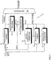
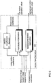
- Figure 1 and Figure 2 are schematic diagrams of a system using motion compensated prediction.
- Figure 1 illustrates an encoder 10 having a motion estimation block and
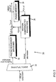
- Figure 2 illustrates a corresponding decoder 30.
- Motion compensated prediction in such a system is outlined below.
- Motion compensated (MC) prediction is a widely recognised compression technique. It utilises the fact that in a typical video sequence, pixel (pel) values in a particular frame can be predicted using pixel values of some other already coded and transmitted frame, given the motion trajectory between these two frames.
- the reference frame R n ( x , y ) is a frame the information for which has previously been coded and transmitted in order that it may be re-constructed in the decoder. Therefore, it may be a frame preceding the one being coded available that is in a frame memory of both the encoder 10 and the decoder 30.
- the pair of values [ ⁇ x ( x , y ), ⁇ y ( x , y )] represents the motion vector of the pixel in location ( x , y ) in the current frame.
- ⁇ x ( x , y ) and ⁇ y ( x , y ) are the values of horizontal and vertical displacements of this pixel, respectively.
- Motion vectors are calculated by a motion field estimation block 12 in the encoder 10 as can be seen in Figure 1 .
- the set of motion vectors of all pixels of the current frame [ ⁇ x ( ⁇ ), ⁇ y ( ⁇ )] is called the motion vector field and is calculated in a motion field coding block 14 before being used to calculate the prediction frame P n ( x , y ) in a motion compensated prediction block 16.
- the motion vector field is also transmitted to the decoder 30.
- a subtractor 18 determines the prediction error E n ( x , y ) between the prediction frame P n ( x , y ) and the frame being coded I n ( x , y ) according to equation 1. Once calculated, the prediction error E n ( x , y ) is compressed in a prediction error coding block 20 to produce a compressed prediction error, denoted by ⁇ n ( x , y ), which is then sent to the decoder 30.
- the compression process typically introduces some loss of information.
- the compressed prediction error ⁇ n ( x , y ) is decoded in a prediction error decoding block 22 so that it is used to generate a reference frame R n ( x , y ) in the encoder 10 which corresponds to the reference frame R n ( x , y ) which is generated in the decoder 30.
- this is done by combining the decoded prediction error ⁇ n ( x , y ) with the prediction frame P n ( x , y ) in an adder 24 to produce the reference frame R n ( x , y ).
- the reference frame R n ( x , y ) is stored in the frame memory 26 of the encoder 10.
- Motion information derived from the motion field coding block 14 and prediction error information derived from the prediction error coding block 20 are combined together in a multiplexing block 28.
- Figure 2 shows a decoder 30.
- a demultiplexer 32 separates the prediction error information and the motion information.
- the prediction error information is provided to a prediction error decoding block 34 and the motion information is provided to a motion compensated prediction block 36.
- the motion compensated prediction block 36 uses motion information and the reference frame R n ( x , y ) stored in the frame memory 38 of the decoder 30 to reconstruct the prediction frame P n ( x , y ).
- segments include at least a few tens of pixels.
- motion vector field model Such a function is called a motion vector field model.
- Polynomial motion models are a widely used family of motion models.
- CMM Mathematique
- motion vectors are described by functions which are linear combinations of 2-dimensional polynomial functions.
- the translational motion model is the simplest model and requires only two coefficients to describe motion vectors of each segment.
- the affine motion model presents a very convenient trade-off between the number of motion coefficients and prediction performance. It is capable of representing some of the common real-life motion types such as translation, rotation, zoom and shear by only a few coefficients.
- the quadratic motion model provides good prediction performance, but it is less popular in coding than the affine model, since it uses more motion coefficients, while the prediction performance is not much better.
- the motion estimation block calculates motion vectors [ ⁇ x ( x , y ), ⁇ y ( x , y )] of the pixels of a given segment S k which minimise some measure of prediction error in the segment.
- a meaningful additive measure of prediction error has the form: ⁇ x i y i ⁇ S k p i h I n x y ⁇ R n x + ⁇ x x y , y + ⁇ y x y
- p i values are scalar constants,
- Equation (9) is a highly non-linear function of many variables and there is thus no practical technique which is capable of always finding the absolute minimum of equation (9) in an acceptable time. Accordingly, motion estimation techniques differ depending on the algorithm for minimisation of the chosen measure of prediction error. Equation (10) is conventionally used as a cost function in motion estimation.
- One technique is the full search. In this technique the value of the cost function is calculated for all the possible combinations of allowed motion coefficient values (restricted by the range and precision with which motion coefficients can be represented). The values of motion coefficients for which the cost function is minimised are chosen to represent the motion vector field.
- the full search technique is usually used only to estimate motion coefficients of the translational motion model and cannot be straightforwardly generalised for other motion models, due to computational burden.
- the computational complexity of the algorithm increases exponentially with the number of motion coefficients used to represent the motion vector field.
- the nth iteration step consists of:
- the main problem associated with the Gauss-Newton algorithm is that it converges only towards local minima, unless the initial motion coefficients lie in the attraction domain of the global minimum. Thus it is necessary to provide the Gauss-Newton algorithm with a sufficiently good initial guess of the actual optimum. Two different techniques are usually used to improve the convergence of the Gauss-Newton algorithm:
- the technique of motion estimation using multi-resolution image pyramids is based on the assumption that low-pass filtering the current frame and the reference frame will erase the local minima and help the algorithm to converge to the global minimum.
- Motion estimation is performed first on the low-pass filtered (smoothed) versions of the reference and current frames, and the result is fed as input to the motion estimation stages using less smoothed images.
- the final estimation is performed on non-smoothed images.
- Some variants of this class additionally down-sample the low-pass filtered images, to reduce the number of computations. For examples of this technique, see H. Sanson, "Region based motion estimation and compensation for digital TV sequence coding," in Proc.
- low-pass filtering of the images does not necessarily erase local minima. Furthermore, this may shift the location of global minimum.
- EP0691789 discloses motion estimation, segmentation and coding.
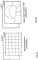
- the method of motion estimation and segmentation of Figure 3 involves a hierarchical approach in which a motion vector updating routine is performed with respect to multiple levels of smaller and smaller regions of a frame.
- the method of processing a frame begins in step 300 at which point it is assumed that a preceding frame exists with reference to which a current frame can be predicted.
- the current frame is segmented or divided into smaller regions of a predetermined shape. This segmentation represents a first segmentation level. Where the predetermined shape is rectangular, the frame may be divided into multiple regions of predetermined equal size.
- the initial motion vector assigned to each of the smaller regions is the motion vector with value zero.
- a frame 400 is divided into multiple regions, each of which is rectangular and has an initial motion vector of zero. The choice of an initial motion vector with value zero is made to lessen the likelihood that noise will be introduced.
- the motion vector of each smaller region is updated according to a motion vector updating routine.
- the next step depends upon whether all the regions in the current segmentation level have been processed according to the motion vector updating routine as indicated in step 320. If all the regions have not been processed, then, as indicated in step 325, the remaining regions are processed serially.
- the preferred sequence begins with a corner region, such as the region corresponding to the upper-left of the current frame. The sequence then proceeds across the upper row to the region corresponding to the upper-right of the current frame. Each subsequent row of regions is processed from left to right until the region corresponding to the lower-right of the current frame has been processed.
- the first step in the motion vector updating routine is shown in step 330 in which a matching error is computed for the current region under consideration by using the initial motion vector assigned to that region.
- the initial motion vector assigned to the current region may be temporarily stored in the file 221 of the memory unit 220 by retrieving it from the motion field memory unit 215.
- the matching error obtained in step 330 is stored in one of the files 241-250 in the memory unit 240.
- step 335 a motion estimation technique is performed with respect to the region under consideration.
- One type of suitable motion estimation technique for use in step 335 involves block matching methods.
- the block matching motion estimation technique is performed for the region under consideration and finds a best matched region in the preceding frame within a predetermined search range. For very low bit-rate applications, search ranges of between ⁇ 7 and ⁇ 15 pixels are suitable.
- the block matching technique performed in step 335 results in a matched motion vector which serves as one of the candidates for refining or updating the motion vector of the particular region under consideration.
- the matched motion vector is a two dimensional vector representing the distance between the location of the current region and the location of the best matched region in the preceding frame.
- GB2317525 discloses a motion estimation system for a video coder. It comprises an input for a video image to be coded, and a series of motion estimators of varying complexity, for estimating a motion vector field between the received image and a reference image. The subsequent motion estimator in the series is selected by a control means if a prediction error associated with the motion vector field estimated by the currently selected motion estimator exceeds a predetermined threshold.
- the invention takes advantage of motion information already available when entering the motion estimation stage. This additional motion information may be predicted from neighbouring segments or inherited from earlier motion estimations for master segments overlapping with the picture element for which motion is to be estimated.
- the motion field estimation means calculates motion coefficients for the at least one picture element by using a set of prediction motion coefficients previously estimated for at least one neighbouring picture element. It may use more than one neighbouring picture element. In this case, it can use an averaged set of prediction motion coefficients averaged from motion information previously estimated for more than one neighbouring picture element.
- nneighbouringn refers to adjacent picture elements in which at least one pixel of one picture element' is directly so next to or overlaps with at least one pixel of another picture element.
- the encoder comprises segmentation means for segmenting a received frame into a plurality of picture elements.
- the segmentation means may derive initial motion coefficients for a master picture element.
- the picture elements are segments.
- the encoder comprises two separate motion estimators, one motion estimator for estimating motion coefficients based upon the predicted motion coefficients and one motion estimator for estimating motion coefficients based on the initial motion coefficients. If the prediction motion coefficients and the initial motion coefficients are both available both of the motion estimators may estimate motion coefficients. In this case, selection means in the encoder may select motion coefficients from either motion estimator to be used to code the current frame. However, if only one set of motion coefficients are available and those of the other motion estimator are not available, one motion estimator estimates motion coefficients.
- the encoder is able to use a combination of the motion estimators having relatively simple motion estimation methods which rely on different assumptions instead of one high complexity method relying on one assumption.
- the encoder determines whether a prediction error associated with motion coefficients estimated by a currently selected method of motion estimation exceeds a predetermined threshold and, if so, it selects a subsequent motion estimation method in a series.
- the encoder comprises a series of motion estimation methods of varying complexity.
- the series may comprises a hierarchy including a zero so motion model, a translational motion model, and an affine motion model.
- the encoder comprises a series of minimisers, including a segment matching minimiser and a Gauss-Newton minimiser and a Quasi-Newton minimiser.
- the encoder dynamically switches between statistically valid assumptions varying in strength. In this way it can achieve statistically low prediction error with relatively little complexity.
- the encoder comprises means for sub-sampling the current frame to produce a sub-sampled frame and for forwarding the sub-sampled frame to the series of motion models.
- the means for sub-sampling may comprise a series of sub-samplers varying in sub-sampling factors.
- the encoder may also comprise control means for selecting and using a subsequent motion model in the series if a prediction error associated with the motion vector field estimated by a currently selected motion estimator unit exceeds a predetermined threshold.
- the control means may be provided to select the amount of sub-sampling during minimisation depending on the change in prediction error.
- the encoder has receiving means for receiving a current frame to be motion coded.
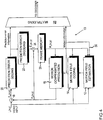
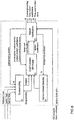
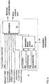
- FIG. 4 An encoder 10 according to the invention is shown in Figure 4 . This figure is similar to Figure 1 and the preceding description applies.
- the encoder of Figure 4 operates in conjunction with a decoder corresponding to that of Figure 2 .
- Figure 4 will now be described.
- Block-based segmentation in the motion field coding block 14 is used in the embodiment of the invention which will now be described.
- Final segmentation consists of 16x16 pixel macro-blocks and 8x8 pixel sub-blocks.
- the prediction error is analysed in the motion field estimation block 12 and a decision is made in the motion field estimation block 12 whether to split the macro-block into four 8x8 sub-blocks. If splitting takes place, motion coefficients of the macro-block are kept in a motion coefficient memory of the motion field estimation block 12 and used as initial motion coefficients in the 8x8 motion estimation. This is described below. Irrespective of whether splitting takes place, final motion coefficients of the macro-block are output to the motion field coding block 14.
- the motion field coding block 14 makes the final decisions on the motion model to be transmitted, whether to use a single 16x16 block or four 8x8 blocks to describe this (16x16) macroblock and the coding of the motion coefficients.
- the same motion estimation system is used independent of the size of the block for which motion is estimated.
- motion information produced by the motion field coding block 14 is fed back to the motion field estimation block 12.
- This motion information comprises both initial motion coefficients and predicted motion coefficients relating to motion of a segment in the current frame relative to a segment in the reference frame.
- This feedback is represented by numeral 30.
- Use of the motion information by the motion field estimation block will be described below.
- the motion field estimation block 12 is shown in Figure 5 .
- This block comprises two motion estimation blocks, namely a full motion estimation block 41 and a refinement motion estimation block 42 and a motion coefficient memory 43.
- motion is first estimated for a 32x32 pixel block in the full motion estimation block 41.
- the resulting motion coefficients are stored in the motion coefficient memory 43 and retrieved and used as initial motion coefficients for the segments (16x16 macro-blocks or 8x8 sub-blocks) created by splitting a previously estimated block.
- the full motion estimation block 41 calculates motion coefficients based on the difference between a current frame and an earlier reference frame.
- the full motion estimation block 41 can include these as a basis to calculate motion coefficients for a segment of the current frame.
- the refinement motion estimation block 42 calculates motion coefficients for a segment of a current frame based on motion coefficients predicted for a segment of the current frame which have previously been calculated.
- the full motion estimation block 41 and the refinement motion estimation block 42 are used. Operation of the motion estimation blocks 41 and 42 is described in greater detail later on with reference to Figures 10 and 11 .
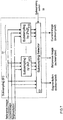
- both motion estimation blocks consist of four main blocks, namely a sub-sampling block 51, a motion model selector block 52, a cost function minimiser block 53 and a result verification block 54.
- the result verification block 54 produces a number of switch signals to control operation of the other three blocks, 51, 52, and 53. Each of these blocks is described below.
- the full motion estimation block 41 and the refinement motion estimation block 42 work in steps. At each step, the motion model, the minimisation method used to minimise the cost function value and the sub-sampling factor are determined. These determinations are made in the result verification block 54 of Figure 6 of the respective motion estimation block.
- Figure 7 shows a block diagram of the sub-sampling block 51.
- the inputs to this block are the reference frame R n ( x , y ) from the frame memory 26 of the encoder 10, the current frame I n ( x , y ), segmentation information from the motion field coding block 14, and information about the required level of sub-sampling. This is provided by a sub-sampling switch signal 55 which is described below.
- the sub-sampling block 51 consists of a bank 61 of sub-samplers 61(1) to 61 (k) and a sub-sampling selector 62 in the form of a multiplexer.
- Each sub-sampler 61(1) to 61 (k) (denoted "Sub-sampling by mxm ”) in the bank 61 subsamples both the reference image and the current image by taking every m th pixel in both horizontal and vertical directions, where m is an integer power of 2.
- the inputs to the sub-sampling selector 62 are the reference R n ( x,y ) and current I n ( x , y ) frames, segmentation information and their sub-sampled versions at various levels, that is a version which has not been sampled and versions sub-sampled by each of the sub-samplers 61(1) to 61 (k).
- the sub-sampling selector uses the sub-sampling switch signal 55 to select an image pair and suitable segmentation to be output.
- the result verification block 54 ( Figure 6 ) is responsible for generating consistent switch signals.
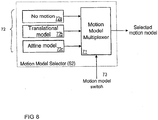
- Figure 8 shows a preferred motion model selector block 52.
- the motion model selector block 52 comprises a motion model multiplexer 71 and a bank 72 of motion models.
- the motion model selector block 52 receives a motion model switch signal 73 from the result verification block 54.
- the motion model selection block 52 is a multiplexer, which makes a selection among the bank 72 of motion models 72a to 72c depending on the motion model switch signal 73.
- the motion models in the bank 72 are "No motion” 72a, "Translational model” 72b and "Affine model” 72c in order of increasing complexity.
- the order of complexity refers to the number of basis functions used in representing the motion. There is a close relationship between the order of complexity of the motion model and computational complexity: as the order of complexity of the motion model increases, the computational complexity of estimation of model coefficients increases.
- there is a "No motion" model72a for which all the motion coefficients are set to zero.
- Other motion models may be used, for example the quadratic motion model. Alternatively, this could be an additionally used model.
- FIG. 9 shows the block diagram of the cost function minimiser block 53. Minimisation of the cost function is performed in this block. It comprises a minimisation method selector 81, a bank 82 of minimisation methods and a minimisation block 83 which calculates a motion coefficient vector and its associated minimised cost function vector.
- the minimisation methods comprise "No minimisation” 82a, "Segment matching” 82b and "Gauss-Newton step” 82c. These minimisation methods are further described below.
- the inputs to the cost function minimiser block 53 are:
- This cost function minimiser block 53 performs minimisation by one of the methods in its bank 82. The selection of the method is determined by a minimisation method switch signal 80 provided by the result verification block 54.
- No minimisation 82a may be selected for any motion model.
- the cost function minimiser block 53 does not perform any cost function optimisation but simply returns the value of the cost function with motion coefficients inputted. This method is used to evaluate the cost function value in the presence of initial motion parameters.
- Segment matching 82b can be selected only for the translational motion model.
- the value of the cost function is calculated for the selected set of values of motion coefficients a 0 and b 0 .
- the values of a 0 and b 0 which yield the smallest value of the prediction error in (6) are chosen as the solution.
- the search is performed on a quantized grid, that is, only the scalar quantized values of a 0 and b 0 are used.
- the search is made by evaluating some or all of the candidate pairs on the grid, and choosing the pair yielding the smallest cost function value.
- Gauss-Newton step 82c can be used for any motion model except “No Motion”. It uses a single Gauss-Newton iteration step to reduce the cost function.
- R. Fletcher Practical Methods of Optimization", Second Edition, John Wiley & Sons, 1987, Chapter 3 and Chapter 6 gives an overview of Gauss-Newton minimisati on.
- the Gauss-Newton method is a specific form of Newton's method, commonly used when the cost function to be minimised is a sum of squares.
- e ( a ) be the cost function as a function of parameter vector a .
- a c be the current parameter vector, being input to the minimisation iteration.
- the Gauss-Newton method approximates the second derivative matrix G by: G ⁇ 2 ⁇ d ⁇ d T where ⁇ d denotes the Jacobian matrix, the columns of which are the first derivative vectors ⁇ d i of the components of d .
- the Gauss-Newton method is not very costly computationally, since it performs only one iteration step.
- the cost function minimiser 53 outputs a minimised cost function value and a motion coefficient vector.
- FIG. 6 shows the details of the full motion estimation 41 and the refinement motion estimation 42 blocks of Figure 5 .
- the verification block 54 provides switch signals.
- the switch signals include the sub-sampling switch signals 55, the motion model switch signal 73, and the minimisation method switch signal 80 which select the sub-sampling factor, motion model and minimisation model, respectively, to be used in the current iteration.
- Any combination of switch signals generated by the result verification block 54 has an underlying set of assumptions.
- the purpose of the result verification block 54 is to optimise these assumptions. Once the set of assumptions is determined, a new set of switch signals is generated and new motion coefficients and a new cost function value result. By comparing these to the previous ones, the result verification block 54 determines:
- switch signals control other blocks in the system. Therefore, determination of the switch signals determines the motion model, minimisation method, and sub-sampling factor to be used in the next iteration(s).
- the result verification block 54 keeps the "current motion coefficients", which are the motion coefficients yielding the smallest value of the cost function so far, and a "current cost function value” which is the smallest value of the cost function so far. If iterations are continued, the current motion coefficients and current cost function value are fed to cost function minimiser 53.
- a convergence flag signal 56 is set by the result verification block 54, and then it outputs the convergence flag signal 56 together with the current motion coefficients as "final motion coefficients" 57 and current cost function value as "final cost function value” 58. These outputs are sent to the motion field coding block 14.
- the result verification block 54 is a powerful tool for keeping the computational complexity of the system at a minimum. By context-dependent switching between sets of assumptions, that is, particular sets of motion models, minimisation methods and degrees of sub-sampling, this block allows high performance motion estimation, involving computationally complex techniques only when necessary.
- the system can find motion coefficients of a segment for:
- the system can be implemented in a variety of ways. For example, the following features may vary:
- only one sub-sampler 61 is provided in the sub-sampling block 51. This sub-sampler causes the signal to be sub-sampled by 2x2.
- the sub-sampling switch signal 55 either chooses this sub-sampler or no sub-sampling at all.
- the motion model selector's bank 72 there are three motion models in the motion model selector's bank 72: the "No motion” model 72a, the “Translational model” 72b and the “Affine model” 72c.
- the segment matching 82a performed is "full-pel segment matching with full search". This operation requires testing all integer-valued motion coefficient pairs in a certain range to find the pair minimising the cost function.
- the Gauss-Newton step is employed only when the motion model is affine.
- Cubic convolution interpolation is used for sub-pixel evaluation.
- Image derivatives are also computed using cubic convolution: the derivatives of the continuous function obtained by cubic convolution interpolation are computed, and they are interpreted as the image derivatives.
- the generation of the new switch signals in the result verification blocks 54 of the full motion estimation block 41 and the refinement motion estimation block 42 can be done in a number of ways. Preferred ways for both motion estimation blocks to generate switch signals are described below.
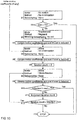
- Figure 10 shows the flow diagram of operations performed in the result verification block 54 of the full motion estimation block 41 according to the preferred embodiment of the invention.
- a first set of assumption (91) of "No motion” are set by switching the sub-sampling level to "None”, the minimisation method is set to "No minimisation” and motion model to "No motion”. If the resulting cost function is below a predefined threshold (92) (denoted “Th1" in Figure 10 ), the search is terminated (913) with zero motion coefficients.
- the next set of assumptions (93) are that a "translational model can approximate the actual motion field" and that "sub-sampling does not shift the global minimum substantially”.
- the sub-sampling switch signal 55 is set to "Sub-sampling by 2x2”
- the model is switched to "Translational model”
- the cost function minimisation method is set to "Segment matching” (93) (sub-sampling is performed to reduce the complexity of operation).
- the best-so-far coefficients are updated (94) by setting the values of a 0 and b 0 in equation 7 to the values computed by segment matching, and setting the other coefficients to zero.
- step 94 If initial motion coefficients are available, for example from a master segment (and stored in the motion coefficient memory block 43), the next assumption is that an "affine model with initial motion coefficients can approximate the actual motion" (95). Now, the motion model is set to "Affine”, “No minimisation” is selected as the minimisation method and the sub-sampling switch signal 55 is set to "None”. Again the cost is evaluated using equation (10) and, if the cost is smaller that the minimum cost of the previous stages (96), initial motion coefficients are stored as the best so far. If there are no initial motion coefficients available, steps 95 and 96 do not occur and step 97 follows step 94.
- the cost function associated with the outcome of the iteration is compared (99) to the best cost function so far obtained. If the resulting cost function is less than the best-so-far cost function, the motion coefficients and best-so-far cost function value are updated by the outcomes of the iteration.
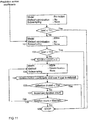
- Figure 11 shows a flow diagram of operations performed in the result verification block 54 of the refinement motion estimation block 42 in the preferred embodiment of the method according to the invention. It can be seen that operations are similar to those performed in Figure 10 .
- the first assumption is "No motion” and, if the resulting cost function value associated with this assumption is below the predefined threshold Th1 (the same as in Figure 10 ), the search is terminated (913) with zero motion coefficients.
- the second assumption is that "the incoming set of predicted motion coefficients already approximates final motion coefficients 52 reasonably well” (101).
- An initial cost is evaluated and compared against a predefined threshold Th3 (102). If the cost is below the threshold, the input motion coefficients are outputted as such (109) and sent to the motion field coding block 14.
- both the full motion estimation block 41 and the refinement motion estimation block 42 are operational (that is if both initial motion coefficients and predicted motion coefficients are available), then, upon receipt of the outputs of these blocks, the motion field coding block 14 compares the "final cost function values" in order to choose one set of motion coefficients to be used.
- a suitable way of comparing these motion coefficients is described in co-pending US patent application titled “Adaptive motion vector field coding” by inventors Jani Lainema and Marta Karczewicz, filed 21 January 2000.
- the predefined thresholds may differ, at different stages of minimisation and/or for different models and/or for different bitrates.
- the system for motion estimation according to the present invention achieves motion estimation with significantly less prediction error than that of previous solutions, while keeping the computational complexity at a statistically low level. This is achieved by providing dynamic switching between statistically valid assumptions varying in strength, via assumption verification at each iteration.
- the present invention specifically provides an improved system for motion estimation of an image segment, using a polynomial motion vector field model.
- Motion estimation is an element of video coding using motion compensated prediction.
- the system finds motion coefficients which yield lower prediction error than prior art solutions, while keeping the computational complexity low.
- This low prediction error enables better performance in terms of video compression.
- the low prediction error is achieved by incorporating the general characteristics of image data and motion into a combination of well-known function minimisation techniques.
Landscapes
- Engineering & Computer Science (AREA)
- Multimedia (AREA)
- Signal Processing (AREA)
- Theoretical Computer Science (AREA)
- Computer Vision & Pattern Recognition (AREA)
- Physics & Mathematics (AREA)
- General Physics & Mathematics (AREA)
- Computing Systems (AREA)
- Compression Or Coding Systems Of Tv Signals (AREA)
- Compression, Expansion, Code Conversion, And Decoders (AREA)
Claims (14)
- Codeur (10) permettant de réaliser un codage à compensation de mouvement d'une séquence de trames vidéo comportant des segments d'image, le codeur comprenant :un moyen faisant mémoire (26) permettant de stocker une trame de référence ;un moyen d'estimation de champ de mouvement (12) permettant d'estimer un mouvement de segment d'image dans une trame actuelle au moyen au moins de la trame de référence, le moyen d'estimation de champ de mouvement comprenant un premier bloc d'estimation de mouvement (41) et un second bloc d'estimation de mouvement (42), le premier bloc d'estimation de mouvement utilisant une série de procédés d'estimation de mouvement de complexité variable et étant conçu pour utiliser des coefficients de mouvement prédits, préalablement estimés pour au moins un premier segment d'image de la trame actuelle, dans l'estimation de premiers coefficients de mouvement pour au moins un second segment d'image de la trame actuelle, et le second bloc d'estimation de mouvement utilisant une série de procédés d'estimation de mouvement de complexité variable et étant conçu pour utiliser des coefficients de mouvement initiaux dans l'estimation de seconds coefficients de mouvement pour ledit au moins un second segment d'image de la trame actuelle, lesdits coefficients de mouvement initiaux étant hérités d'une estimation de mouvement antérieure réalisée sur un segment d'image maître, dont la division a créé ledit second segment d'image, les premier et second blocs d'estimation de mouvement comprenant un moyen permettant de sélectionner et d'utiliser un procédé d'estimation de mouvement ultérieur dans la série (71) si une fonction de coût représentant une mesure d'erreur de prédiction associée à des coefficients de mouvement estimés par un procédé d'estimation de mouvement actuellement sélectionné dépasse un seuil prédéterminé ; etun bloc de codage de champ de mouvement conçu, si le premier bloc d'estimation de mouvement et le second bloc d'estimation de mouvement sont opérationnels et à la réception des premier et second coefficients de mouvement, pour choisir le premier ou le second coefficient de mouvement à utiliser pour représenter le mouvement du second segment d'image.
- Codeur (10) selon la revendication 1, dans lequel le moyen d'estimation de champ de mouvement (12) est conçu pour calculer des coefficients de mouvement pour l'au moins un second segment d'image au moyen d'un ensemble de coefficients de mouvement prédits préalablement estimés pour au moins un segment d'image de voisinage.
- Codeur (10) selon la revendication 1 ou 2, dans lequel le moyen d'estimation de champ de mouvement (12) est conçu pour calculer des coefficients de mouvement pour l'au moins un second segment d'image au moyen d'un ensemble de coefficients de mouvement prédits préalablement estimés pour plusieurs segments d'image de voisinage.
- Codeur (10) selon l'une quelconque des revendications précédentes, dans lequel le moyen d'estimation de champ de mouvement (12) est conçu pour utiliser un ensemble moyenné de coefficients de mouvement prédits moyennés à partir d'une information de mouvement préalablement estimée pour plusieurs segments d'image de voisinage.
- Codeur (10) selon l'une quelconque des revendications précédentes, dans lequel un moyen de segmentation est conçu pour segmenter une trame reçue en une pluralité de segments d'image.
- Codeur (10) selon l'une quelconque des revendications précédentes, dans lequel la série de procédés d'estimation de mouvement (52) comprend une hiérarchie comportant un modèle de mouvement nul (72a), un modèle de mouvement de translation (72b) et un modèle de mouvement affine (72c).
- Codeur (10) selon l'une quelconque des revendications précédentes, comprenant un moyen de sous-échantillonnage (51) de la trame actuelle afin de produire une trame sous-échantillonnée, et de transfert de la trame sous-échantillonnée à la série de procédés d'estimation de mouvement.
- Codeur (10) selon la revendication 7, comprenant un moyen de contrôle permettant de sélectionner l'importance du sous-échantillonnage (62) pendant la minimisation, selon la variation de la fonction de coût représentant une mesure d'erreur de prédiction.
- Codeur (10) selon la revendication 7 ou 8, dans laquelle le moyen de sous-échantillonnage (51) comprend une série de sous-échantillonneurs (61 (1), ..., 61 (k)) variant dans des facteurs de sous-échantillonnage.
- Codeur (10) selon l'une quelconque des revendications précédentes, dans lequel le moyen d'estimation de champ de mouvement comprend une série de minimiseurs (82), comprenant un minimiseur par comparaison de segment (82a), un minimiseur de Gauss-Newton (82b) et un minimiseur de Quasi-Newton (82c).
- Codec comprenant un codeur (10) selon l'une quelconque des revendications précédentes, et un décodeur (30).
- Terminal mobile comprenant un codeur (10) selon l'une quelconque des revendications 1 à 10 ou un codec selon la revendication 11.
- Réseau de communication de données comprenant un codeur (10) selon l'une quelconque des revendications 1 à 10.
- Procédé de réalisation d'un codage à compensation de mouvement d'une séquence de trames vidéo comportant des segments d'image, le procédé consistant à :stocker une trame de référence ;estimer un mouvement de segment d'image dans une trame actuelle au moyen au moins de la trame de référence, par :un premier bloc d'estimation de mouvement (42) utilisant une série de procédés d'estimation de mouvement de complexité variable et utilisant un ensemble de coefficients de mouvement prédits, préalablement estimés pour au moins un premier segment d'image de la trame actuelle, dans l'estimation de premiers coefficients de mouvement pour au moins un second segment d'image de la trame actuelle ;un second bloc d'estimation de mouvement (41) utilisant une série de procédés d'estimation de mouvement de complexité variable et utilisant des coefficients de mouvement initiaux dans l'estimation de seconds coefficients de mouvement pour ledit au moins un second segment d'image de la trame actuelle, lesdits coefficients de mouvement initiaux étant hérités d'une estimation de mouvement antérieure réalisée sur un segment d'image maître, dont la division a créé ledit second segment d'image ;les premier et second blocs d'estimation de mouvement comprenant sélectionnant et utilisant un procédé d'estimation de mouvement ultérieur dans la série (71) si une fonction de coût représentant une mesure d'erreur de prédiction associée à des coefficients de mouvement estimés par un procédé d'estimation de mouvement actuellement sélectionné dépasse un seuil prédéterminé ; etun bloc de codage de champ de mouvement choisissant, si le premier bloc d'estimation de mouvement et le second bloc d'estimation de mouvement sont opérationnels et à la réception des premier et second coefficients de mouvement, le premier ou le second coefficient de mouvement à utiliser pour représenter le mouvement du second segment d'image.
Applications Claiming Priority (3)
| Application Number | Priority Date | Filing Date | Title |
|---|---|---|---|
| US488880 | 1995-06-09 | ||
| US48888000A | 2000-01-21 | 2000-01-21 | |
| EP01902440A EP1279293A1 (fr) | 2000-01-21 | 2001-01-19 | Procede et systeme d'estimation de mouvement pour un videocodeur |
Related Parent Applications (2)
| Application Number | Title | Priority Date | Filing Date |
|---|---|---|---|
| EP01902440A Division EP1279293A1 (fr) | 2000-01-21 | 2001-01-19 | Procede et systeme d'estimation de mouvement pour un videocodeur |
| EP01902440.5 Division | 2001-01-19 |
Publications (3)
| Publication Number | Publication Date |
|---|---|
| EP1404135A2 EP1404135A2 (fr) | 2004-03-31 |
| EP1404135A3 EP1404135A3 (fr) | 2007-11-21 |
| EP1404135B1 true EP1404135B1 (fr) | 2016-12-14 |
Family
ID=23941488
Family Applications (2)
| Application Number | Title | Priority Date | Filing Date |
|---|---|---|---|
| EP01902440A Withdrawn EP1279293A1 (fr) | 2000-01-21 | 2001-01-19 | Procede et systeme d'estimation de mouvement pour un videocodeur |
| EP03021078.5A Expired - Lifetime EP1404135B1 (fr) | 2000-01-21 | 2001-01-19 | Système et méthode d'estimation de mouvement pour un codeur vidéo |
Family Applications Before (1)
| Application Number | Title | Priority Date | Filing Date |
|---|---|---|---|
| EP01902440A Withdrawn EP1279293A1 (fr) | 2000-01-21 | 2001-01-19 | Procede et systeme d'estimation de mouvement pour un videocodeur |
Country Status (5)
| Country | Link |
|---|---|
| US (1) | US7200174B2 (fr) |
| EP (2) | EP1279293A1 (fr) |
| CN (1) | CN1193620C (fr) |
| AU (1) | AU2001230273A1 (fr) |
| WO (1) | WO2001054418A1 (fr) |
Families Citing this family (38)
| Publication number | Priority date | Publication date | Assignee | Title |
|---|---|---|---|---|
| EP1189169A1 (fr) * | 2000-09-07 | 2002-03-20 | STMicroelectronics S.r.l. | Une architecture VLSI, particulièrement connue pour des applications d'estimation de mouvement |
| WO2003055226A1 (fr) * | 2001-12-21 | 2003-07-03 | Koninklijke Philips Electronics N.V. | Procede et appareil d'interpolation temporelle compensee de mouvement de sequences video |
| KR20040022697A (ko) * | 2002-09-09 | 2004-03-16 | 한국전자통신연구원 | 영상 데이터 압축을 위한 움직임 추정 장치 |
| BR0307197A (pt) | 2002-11-25 | 2005-08-23 | Matsushita Electric Ind Co Ltd | Método de compensação de movimento, método de codificação de imagem e método de decodificação de imagem |
| US7471724B2 (en) * | 2003-06-23 | 2008-12-30 | Vichip Corp. Limited | Method and apparatus for adaptive multiple-dimensional signal sequences encoding/decoding |
| US8094711B2 (en) * | 2003-09-17 | 2012-01-10 | Thomson Licensing | Adaptive reference picture generation |
| US20050286777A1 (en) * | 2004-06-27 | 2005-12-29 | Roger Kumar | Encoding and decoding images |
| CN100370836C (zh) * | 2004-08-02 | 2008-02-20 | 华为技术有限公司 | 基于率失真优化的运动预测方法 |
| US7463753B2 (en) * | 2004-09-15 | 2008-12-09 | Raytheon Company | FLIR-to-missile boresight correlation and non-uniformity compensation of the missile seeker |
| DE112004002977T5 (de) * | 2004-10-14 | 2007-09-20 | Intel Corporation, Santa Clara | Schnelle Multi-Frame-Bewegungsabschätzung mit adaptiven Suchstrategien |
| US7609765B2 (en) * | 2004-12-02 | 2009-10-27 | Intel Corporation | Fast multi-frame motion estimation with adaptive search strategies |
| CN101754011B (zh) * | 2004-10-14 | 2013-01-02 | 英特尔公司 | 采用自适应搜索策略的快速多帧运动估计方法 |
| DE602005026558D1 (de) * | 2004-12-09 | 2011-04-07 | Thomson Licensing | Verfahren und vorrichtung zum erzeugen von bewegungskompensierten bildern |
| KR100746022B1 (ko) * | 2005-06-14 | 2007-08-06 | 삼성전자주식회사 | 서브픽셀 움직임 추정시 모델 스위칭을 통한 압축 효율을증가시키는 인코딩 방법 및 장치 |
| US9258519B2 (en) * | 2005-09-27 | 2016-02-09 | Qualcomm Incorporated | Encoder assisted frame rate up conversion using various motion models |
| US8705630B2 (en) * | 2006-02-10 | 2014-04-22 | Nvidia Corporation | Adapting one type of encoder to another type of encoder |
| US8605786B2 (en) * | 2007-09-04 | 2013-12-10 | The Regents Of The University Of California | Hierarchical motion vector processing method, software and devices |
| EP2213101A4 (fr) * | 2007-11-20 | 2011-08-10 | Ubstream Ltd | Procédé et système pour compresser des flux vidéo numériques |
| JP5263763B2 (ja) * | 2008-08-21 | 2013-08-14 | 株式会社ザクティ | 電子カメラ |
| US9179161B2 (en) * | 2009-05-20 | 2015-11-03 | Nissim Nissimyan | Video encoding |
| CN106231336B (zh) | 2010-04-13 | 2020-06-12 | Ge视频压缩有限责任公司 | 解码器、解码方法、编码器以及编码方法 |
| KR102405997B1 (ko) | 2010-04-13 | 2022-06-07 | 지이 비디오 컴프레션, 엘엘씨 | 평면 간 예측 |
| KR102480988B1 (ko) | 2010-04-13 | 2022-12-26 | 지이 비디오 컴프레션, 엘엘씨 | 샘플 영역 병합 |
| EP4407986A2 (fr) | 2010-04-13 | 2024-07-31 | GE Video Compression, LLC | Héritage dans une subdivision en plusieurs arborescences d'une matrice d'échantillons |
| US20110317773A1 (en) * | 2010-06-24 | 2011-12-29 | Worldplay (Barbados) Inc. | Method for downsampling images |
| US8755437B2 (en) | 2011-03-17 | 2014-06-17 | Mediatek Inc. | Method and apparatus for derivation of spatial motion vector candidate and motion vector prediction candidate |
| JP5808427B2 (ja) | 2011-03-14 | 2015-11-10 | メディアテック インコーポレイテッド | 動きベクトル候補及び動きベクトル予測候補の導出のための方法及び装置 |
| US20130083845A1 (en) | 2011-09-30 | 2013-04-04 | Research In Motion Limited | Methods and devices for data compression using a non-uniform reconstruction space |
| EP2595382B1 (fr) | 2011-11-21 | 2019-01-09 | BlackBerry Limited | Procédés et dispositifs de codage et de décodage de filtres de domaine de transformation |
| EP2683165B1 (fr) | 2012-07-04 | 2015-10-14 | Thomson Licensing | Procédé de codage et de décodage d'un bloc de pixels à partir d'un modèle de mouvement |
| CN110557631B (zh) * | 2015-03-10 | 2023-10-20 | 华为技术有限公司 | 图像预测方法和相关设备 |
| WO2017124298A1 (fr) * | 2016-01-19 | 2017-07-27 | 北京大学深圳研究生院 | Procédé de codage et de décodage vidéo, et procédé de prédiction intertrame, appareil et système associés |
| US10225573B1 (en) | 2017-01-31 | 2019-03-05 | Google Llc | Video coding using parameterized motion models |
| US10701390B2 (en) * | 2017-03-14 | 2020-06-30 | Qualcomm Incorporated | Affine motion information derivation |
| WO2018169571A1 (fr) * | 2017-03-15 | 2018-09-20 | Google Llc | Modèles de mouvement paramétrés à base de segmentation |
| KR102463478B1 (ko) * | 2018-01-26 | 2022-11-04 | 에이치에프아이 이노베이션 인크. | 비디오 코딩 시스템을 위한 아핀 인터 예측 방법 및 장치 |
| US20190357770A1 (en) * | 2018-05-11 | 2019-11-28 | Sheldon Jordan | Systems and Methods for Imaging of Neurovascular-Coupling |
| WO2020061423A1 (fr) | 2018-09-21 | 2020-03-26 | Vid Scale, Inc. | Estimation de mouvement affine de codage vidéo à base de modèle affine |
Family Cites Families (8)
| Publication number | Priority date | Publication date | Assignee | Title |
|---|---|---|---|---|
| SE469866B (sv) * | 1991-04-12 | 1993-09-27 | Dv Sweden Ab | Metod för estimering av rörelseinnehåll i videosignaler |
| US5594504A (en) * | 1994-07-06 | 1997-01-14 | Lucent Technologies Inc. | Predictive video coding using a motion vector updating routine |
| US5608458A (en) * | 1994-10-13 | 1997-03-04 | Lucent Technologies Inc. | Method and apparatus for a region-based approach to coding a sequence of video images |
| US5825426A (en) * | 1994-10-18 | 1998-10-20 | Intel Corporation | Video subsampling mode decisions based upon interpolation error measures |
| US6163575A (en) * | 1995-10-20 | 2000-12-19 | Nokia Mobile Phones Limited | Motion vector field coding |
| US5929940A (en) * | 1995-10-25 | 1999-07-27 | U.S. Philips Corporation | Method and device for estimating motion between images, system for encoding segmented images |
| US6212235B1 (en) * | 1996-04-19 | 2001-04-03 | Nokia Mobile Phones Ltd. | Video encoder and decoder using motion-based segmentation and merging |
| GB2317525B (en) * | 1996-09-20 | 2000-11-08 | Nokia Mobile Phones Ltd | A video coding system |
-
2001
- 2001-01-19 CN CNB018067417A patent/CN1193620C/zh not_active Expired - Fee Related
- 2001-01-19 AU AU2001230273A patent/AU2001230273A1/en not_active Abandoned
- 2001-01-19 EP EP01902440A patent/EP1279293A1/fr not_active Withdrawn
- 2001-01-19 WO PCT/FI2001/000047 patent/WO2001054418A1/fr not_active Application Discontinuation
- 2001-01-19 EP EP03021078.5A patent/EP1404135B1/fr not_active Expired - Lifetime
-
2003
- 2003-05-19 US US10/440,841 patent/US7200174B2/en not_active Expired - Lifetime
Non-Patent Citations (1)
| Title |
|---|
| None * |
Also Published As
| Publication number | Publication date |
|---|---|
| CN1418437A (zh) | 2003-05-14 |
| EP1279293A1 (fr) | 2003-01-29 |
| US7200174B2 (en) | 2007-04-03 |
| CN1193620C (zh) | 2005-03-16 |
| WO2001054418A1 (fr) | 2001-07-26 |
| EP1404135A2 (fr) | 2004-03-31 |
| US20030202596A1 (en) | 2003-10-30 |
| AU2001230273A1 (en) | 2001-07-31 |
| EP1404135A3 (fr) | 2007-11-21 |
Similar Documents
| Publication | Publication Date | Title |
|---|---|---|
| EP1404135B1 (fr) | Système et méthode d'estimation de mouvement pour un codeur vidéo | |
| EP0927494B1 (fr) | Systeme et procede d'estimation du mouvement pour codeur video | |
| EP1228645B1 (fr) | Codage adaptatif de champ vectoriel de mouvement | |
| US6711209B1 (en) | Adaptive motion vector field coding | |
| US7580456B2 (en) | Prediction-based directional fractional pixel motion estimation for video coding | |
| US5786860A (en) | High speed block matching for bi-directional motion vector estimation | |
| US5760846A (en) | Apparatus for estimating motion vectors for feature points of a video signal | |
| US20060245497A1 (en) | Device and method for fast block-matching motion estimation in video encoders | |
| US8625678B2 (en) | Method for scalable video coding on a plurality of space resolution levels | |
| US20090067504A1 (en) | Real-time video coding/decoding | |
| WO1997040628A1 (fr) | Codeur et decodeur video mettant en ×uvre des procedures de segmentation et de fusion regies par le mouvement | |
| WO2002065784A1 (fr) | Procede de codage et de decodage d'informations de mouvement | |
| Yang et al. | A low-complexity region-based video coder using backward morphological motion field segmentation | |
| Accame et al. | High performance hierarchical block-based motion estimation for real-time video coding | |
| WO2000007375A1 (fr) | Systeme de codage video | |
| Salembier | Motion-compensated partition coding | |
| Kim et al. | Multilevel Residual Motion Compensation for High Efficiency Video Coding | |
| KR100238891B1 (ko) | 개선된 움직임 추정 장치 및 그 추정 방법 | |
| KR100203658B1 (ko) | 물체의 윤곽 부호화를 위한 움직임 추정장치 | |
| KR100196873B1 (ko) | 영상부호기의 움직임변위정보 탐색방법 | |
| Mishra et al. | Various techniques for low bit rate video coding | |
| Yoon et al. | Region-based video coding using a multiscale image segmentation | |
| Panusopone et al. | An Efficient Implementation of Unrestricted Motion Compensation in Video Encoder | |
| Xie et al. | Improved motion estimation algorithm with post processing and its application in motion-compensated interpolation | |
| Khalil et al. | DCT of spatially adaptive subsampled interframes for image sequence coding |
Legal Events
| Date | Code | Title | Description |
|---|---|---|---|
| PUAI | Public reference made under article 153(3) epc to a published international application that has entered the european phase |
Free format text: ORIGINAL CODE: 0009012 |
|
| AC | Divisional application: reference to earlier application |
Ref document number: 1279293 Country of ref document: EP Kind code of ref document: P |
|
| AK | Designated contracting states |
Kind code of ref document: A2 Designated state(s): AT BE CH CY DE DK ES FI FR GB GR IE IT LI LU MC NL PT SE TR |
|
| PUAL | Search report despatched |
Free format text: ORIGINAL CODE: 0009013 |
|
| AK | Designated contracting states |
Kind code of ref document: A3 Designated state(s): AT BE CH CY DE DK ES FI FR GB GR IE IT LI LU MC NL PT SE TR |
|
| RIC1 | Information provided on ipc code assigned before grant |
Ipc: H04N 7/26 20060101ALI20071016BHEP Ipc: H04N 7/36 20060101AFI20071016BHEP |
|
| 17P | Request for examination filed |
Effective date: 20080414 |
|
| AKX | Designation fees paid |
Designated state(s): DE FI FR GB NL |
|
| 17Q | First examination report despatched |
Effective date: 20080826 |
|
| RAP1 | Party data changed (applicant data changed or rights of an application transferred) |
Owner name: NOKIA CORPORATION |
|
| RAP1 | Party data changed (applicant data changed or rights of an application transferred) |
Owner name: NOKIA TECHNOLOGIES OY |
|
| REG | Reference to a national code |
Ref country code: DE Ref legal event code: R079 Ref document number: 60150246 Country of ref document: DE Free format text: PREVIOUS MAIN CLASS: H04N0007260000 Ipc: H04N0019510000 |
|
| GRAP | Despatch of communication of intention to grant a patent |
Free format text: ORIGINAL CODE: EPIDOSNIGR1 |
|
| INTG | Intention to grant announced |
Effective date: 20160622 |
|
| RIC1 | Information provided on ipc code assigned before grant |
Ipc: H04N 19/557 20140101ALI20160613BHEP Ipc: H04N 19/513 20140101ALI20160613BHEP Ipc: H04N 19/56 20140101ALI20160613BHEP Ipc: H04N 19/51 20140101AFI20160613BHEP Ipc: H04N 19/53 20140101ALI20160613BHEP Ipc: H04N 19/52 20140101ALI20160613BHEP Ipc: H04N 19/543 20140101ALI20160613BHEP Ipc: G06T 7/20 20060101ALI20160613BHEP |
|
| GRAS | Grant fee paid |
Free format text: ORIGINAL CODE: EPIDOSNIGR3 |
|
| GRAA | (expected) grant |
Free format text: ORIGINAL CODE: 0009210 |
|
| AC | Divisional application: reference to earlier application |
Ref document number: 1279293 Country of ref document: EP Kind code of ref document: P |
|
| AK | Designated contracting states |
Kind code of ref document: B1 Designated state(s): DE FI FR GB NL |
|
| REG | Reference to a national code |
Ref country code: GB Ref legal event code: FG4D |
|
| REG | Reference to a national code |
Ref country code: DE Ref legal event code: R096 Ref document number: 60150246 Country of ref document: DE |
|
| REG | Reference to a national code |
Ref country code: NL Ref legal event code: MP Effective date: 20161214 |
|
| PGFP | Annual fee paid to national office [announced via postgrant information from national office to epo] |
Ref country code: DE Payment date: 20170117 Year of fee payment: 17 |
|
| PG25 | Lapsed in a contracting state [announced via postgrant information from national office to epo] |
Ref country code: FI Free format text: LAPSE BECAUSE OF FAILURE TO SUBMIT A TRANSLATION OF THE DESCRIPTION OR TO PAY THE FEE WITHIN THE PRESCRIBED TIME-LIMIT Effective date: 20161214 |
|
| PG25 | Lapsed in a contracting state [announced via postgrant information from national office to epo] |
Ref country code: NL Free format text: LAPSE BECAUSE OF FAILURE TO SUBMIT A TRANSLATION OF THE DESCRIPTION OR TO PAY THE FEE WITHIN THE PRESCRIBED TIME-LIMIT Effective date: 20161214 |
|
| REG | Reference to a national code |
Ref country code: DE Ref legal event code: R097 Ref document number: 60150246 Country of ref document: DE |
|
| PLBE | No opposition filed within time limit |
Free format text: ORIGINAL CODE: 0009261 |
|
| STAA | Information on the status of an ep patent application or granted ep patent |
Free format text: STATUS: NO OPPOSITION FILED WITHIN TIME LIMIT |
|
| REG | Reference to a national code |
Ref country code: FR Ref legal event code: ST Effective date: 20170929 |
|
| PG25 | Lapsed in a contracting state [announced via postgrant information from national office to epo] |
Ref country code: FR Free format text: LAPSE BECAUSE OF NON-PAYMENT OF DUE FEES Effective date: 20170214 |
|
| 26N | No opposition filed |
Effective date: 20170915 |
|
| GBPC | Gb: european patent ceased through non-payment of renewal fee |
Effective date: 20170314 |
|
| PG25 | Lapsed in a contracting state [announced via postgrant information from national office to epo] |
Ref country code: GB Free format text: LAPSE BECAUSE OF NON-PAYMENT OF DUE FEES Effective date: 20170314 |
|
| REG | Reference to a national code |
Ref country code: DE Ref legal event code: R119 Ref document number: 60150246 Country of ref document: DE |
|
| PG25 | Lapsed in a contracting state [announced via postgrant information from national office to epo] |
Ref country code: DE Free format text: LAPSE BECAUSE OF NON-PAYMENT OF DUE FEES Effective date: 20180801 |