JP5329709B2 - Liquid precursor solution mixture and precursor vapor composition - Google Patents
Liquid precursor solution mixture and precursor vapor composition Download PDFInfo
- Publication number
- JP5329709B2 JP5329709B2 JP2012278476A JP2012278476A JP5329709B2 JP 5329709 B2 JP5329709 B2 JP 5329709B2 JP 2012278476 A JP2012278476 A JP 2012278476A JP 2012278476 A JP2012278476 A JP 2012278476A JP 5329709 B2 JP5329709 B2 JP 5329709B2
- Authority
- JP
- Japan
- Prior art keywords
- pzt
- precursor
- ferroelectric
- film
- liquid
- Prior art date
- Legal status (The legal status is an assumption and is not a legal conclusion. Google has not performed a legal analysis and makes no representation as to the accuracy of the status listed.)
- Expired - Fee Related
Links
- 239000002243 precursor Substances 0.000 title claims description 53
- 239000000203 mixture Substances 0.000 title claims description 48
- 239000012705 liquid precursor Substances 0.000 title claims description 19
- 239000007788 liquid Substances 0.000 claims abstract description 23
- 239000000243 solution Substances 0.000 claims description 30
- 239000000758 substrate Substances 0.000 claims description 30
- 239000010936 titanium Substances 0.000 claims description 29
- 239000002904 solvent Substances 0.000 claims description 16
- 229910052719 titanium Inorganic materials 0.000 claims description 14
- 239000007789 gas Substances 0.000 claims description 12
- 229910052726 zirconium Inorganic materials 0.000 claims description 12
- DIOQZVSQGTUSAI-UHFFFAOYSA-N decane Chemical compound CCCCCCCCCC DIOQZVSQGTUSAI-UHFFFAOYSA-N 0.000 claims description 10
- 229910052760 oxygen Inorganic materials 0.000 claims description 8
- RTAQQCXQSZGOHL-UHFFFAOYSA-N Titanium Chemical compound [Ti] RTAQQCXQSZGOHL-UHFFFAOYSA-N 0.000 claims description 7
- QCWXUUIWCKQGHC-UHFFFAOYSA-N Zirconium Chemical compound [Zr] QCWXUUIWCKQGHC-UHFFFAOYSA-N 0.000 claims description 7
- TVMXDCGIABBOFY-UHFFFAOYSA-N octane Chemical compound CCCCCCCC TVMXDCGIABBOFY-UHFFFAOYSA-N 0.000 claims description 6
- 229920000768 polyamine Polymers 0.000 claims description 6
- 239000012159 carrier gas Substances 0.000 claims description 5
- 230000001590 oxidative effect Effects 0.000 claims description 5
- 239000003446 ligand Substances 0.000 claims description 4
- 229910052786 argon Inorganic materials 0.000 claims description 3
- 239000011259 mixed solution Substances 0.000 claims 2
- 239000012495 reaction gas Substances 0.000 claims 1
- 239000000463 material Substances 0.000 abstract description 102
- 239000010408 film Substances 0.000 abstract description 85
- 239000003990 capacitor Substances 0.000 abstract description 57
- 238000000034 method Methods 0.000 abstract description 57
- 239000010409 thin film Substances 0.000 abstract description 26
- 238000002488 metal-organic chemical vapour deposition Methods 0.000 abstract description 24
- 238000012986 modification Methods 0.000 abstract description 5
- 230000004048 modification Effects 0.000 abstract description 5
- 239000003607 modifier Substances 0.000 abstract description 5
- 229910052791 calcium Inorganic materials 0.000 abstract description 4
- 229910052758 niobium Inorganic materials 0.000 abstract description 4
- 229910052712 strontium Inorganic materials 0.000 abstract description 4
- HFGPZNIAWCZYJU-UHFFFAOYSA-N lead zirconate titanate Chemical compound [O-2].[O-2].[O-2].[O-2].[O-2].[Ti+4].[Zr+4].[Pb+2] HFGPZNIAWCZYJU-UHFFFAOYSA-N 0.000 abstract description 3
- 230000008569 process Effects 0.000 description 33
- 230000010287 polarization Effects 0.000 description 32
- 238000000151 deposition Methods 0.000 description 29
- 230000005684 electric field Effects 0.000 description 26
- 230000008021 deposition Effects 0.000 description 23
- 230000004888 barrier function Effects 0.000 description 20
- 239000012071 phase Substances 0.000 description 17
- 238000009792 diffusion process Methods 0.000 description 16
- 239000004065 semiconductor Substances 0.000 description 13
- 239000004020 conductor Substances 0.000 description 12
- 230000000694 effects Effects 0.000 description 11
- 238000004519 manufacturing process Methods 0.000 description 10
- 230000015572 biosynthetic process Effects 0.000 description 9
- 210000003127 knee Anatomy 0.000 description 9
- BASFCYQUMIYNBI-UHFFFAOYSA-N platinum Substances [Pt] BASFCYQUMIYNBI-UHFFFAOYSA-N 0.000 description 9
- 238000012545 processing Methods 0.000 description 9
- 238000012360 testing method Methods 0.000 description 9
- WYURNTSHIVDZCO-UHFFFAOYSA-N Tetrahydrofuran Chemical compound C1CCOC1 WYURNTSHIVDZCO-UHFFFAOYSA-N 0.000 description 8
- 150000001875 compounds Chemical class 0.000 description 8
- 230000000875 corresponding effect Effects 0.000 description 8
- 239000012212 insulator Substances 0.000 description 8
- 239000011159 matrix material Substances 0.000 description 8
- 241000894007 species Species 0.000 description 8
- 238000001704 evaporation Methods 0.000 description 7
- 230000006870 function Effects 0.000 description 7
- 238000005259 measurement Methods 0.000 description 7
- VYPSYNLAJGMNEJ-UHFFFAOYSA-N Silicium dioxide Chemical compound O=[Si]=O VYPSYNLAJGMNEJ-UHFFFAOYSA-N 0.000 description 6
- 230000008020 evaporation Effects 0.000 description 6
- 229910052745 lead Inorganic materials 0.000 description 6
- 230000004044 response Effects 0.000 description 6
- 230000008901 benefit Effects 0.000 description 5
- 239000003153 chemical reaction reagent Substances 0.000 description 5
- 230000002596 correlated effect Effects 0.000 description 5
- 230000007423 decrease Effects 0.000 description 5
- 230000001419 dependent effect Effects 0.000 description 5
- 238000005530 etching Methods 0.000 description 5
- 229910052741 iridium Inorganic materials 0.000 description 5
- GKOZUEZYRPOHIO-UHFFFAOYSA-N iridium atom Chemical compound [Ir] GKOZUEZYRPOHIO-UHFFFAOYSA-N 0.000 description 5
- 229910052751 metal Inorganic materials 0.000 description 5
- 239000002184 metal Substances 0.000 description 5
- KFZMGEQAYNKOFK-UHFFFAOYSA-N Isopropanol Chemical compound CC(C)O KFZMGEQAYNKOFK-UHFFFAOYSA-N 0.000 description 4
- 238000002441 X-ray diffraction Methods 0.000 description 4
- 230000006399 behavior Effects 0.000 description 4
- 238000000354 decomposition reaction Methods 0.000 description 4
- 230000003247 decreasing effect Effects 0.000 description 4
- 230000005284 excitation Effects 0.000 description 4
- 230000015654 memory Effects 0.000 description 4
- 238000000059 patterning Methods 0.000 description 4
- 229920002120 photoresistant polymer Polymers 0.000 description 4
- YLQBMQCUIZJEEH-UHFFFAOYSA-N tetrahydrofuran Natural products C=1C=COC=1 YLQBMQCUIZJEEH-UHFFFAOYSA-N 0.000 description 4
- 229910052581 Si3N4 Inorganic materials 0.000 description 3
- 238000000137 annealing Methods 0.000 description 3
- QVGXLLKOCUKJST-UHFFFAOYSA-N atomic oxygen Chemical compound [O] QVGXLLKOCUKJST-UHFFFAOYSA-N 0.000 description 3
- 238000005229 chemical vapour deposition Methods 0.000 description 3
- 239000013078 crystal Substances 0.000 description 3
- 238000005137 deposition process Methods 0.000 description 3
- 230000014759 maintenance of location Effects 0.000 description 3
- 238000004377 microelectronic Methods 0.000 description 3
- 125000002524 organometallic group Chemical group 0.000 description 3
- 239000001301 oxygen Substances 0.000 description 3
- 239000002245 particle Substances 0.000 description 3
- 238000002161 passivation Methods 0.000 description 3
- 238000011160 research Methods 0.000 description 3
- 235000012239 silicon dioxide Nutrition 0.000 description 3
- 239000000377 silicon dioxide Substances 0.000 description 3
- HQVNEWCFYHHQES-UHFFFAOYSA-N silicon nitride Chemical compound N12[Si]34N5[Si]62N3[Si]51N64 HQVNEWCFYHHQES-UHFFFAOYSA-N 0.000 description 3
- 239000007787 solid Substances 0.000 description 3
- XKRFYHLGVUSROY-UHFFFAOYSA-N Argon Chemical compound [Ar] XKRFYHLGVUSROY-UHFFFAOYSA-N 0.000 description 2
- UQZIWOQVLUASCR-UHFFFAOYSA-N alumane;titanium Chemical compound [AlH3].[Ti] UQZIWOQVLUASCR-UHFFFAOYSA-N 0.000 description 2
- 238000004458 analytical method Methods 0.000 description 2
- 238000006243 chemical reaction Methods 0.000 description 2
- RKTYLMNFRDHKIL-UHFFFAOYSA-N copper;5,10,15,20-tetraphenylporphyrin-22,24-diide Chemical compound [Cu+2].C1=CC(C(=C2C=CC([N-]2)=C(C=2C=CC=CC=2)C=2C=CC(N=2)=C(C=2C=CC=CC=2)C2=CC=C3[N-]2)C=2C=CC=CC=2)=NC1=C3C1=CC=CC=C1 RKTYLMNFRDHKIL-UHFFFAOYSA-N 0.000 description 2
- 238000013461 design Methods 0.000 description 2
- 238000011161 development Methods 0.000 description 2
- HTXDPTMKBJXEOW-UHFFFAOYSA-N dioxoiridium Chemical compound O=[Ir]=O HTXDPTMKBJXEOW-UHFFFAOYSA-N 0.000 description 2
- 239000002019 doping agent Substances 0.000 description 2
- 238000005516 engineering process Methods 0.000 description 2
- 238000002474 experimental method Methods 0.000 description 2
- 229910000457 iridium oxide Inorganic materials 0.000 description 2
- 229910052451 lead zirconate titanate Inorganic materials 0.000 description 2
- 239000012528 membrane Substances 0.000 description 2
- 230000006911 nucleation Effects 0.000 description 2
- 238000010899 nucleation Methods 0.000 description 2
- 239000007800 oxidant agent Substances 0.000 description 2
- NFHFRUOZVGFOOS-UHFFFAOYSA-N palladium;triphenylphosphane Chemical compound [Pd].C1=CC=CC=C1P(C=1C=CC=CC=1)C1=CC=CC=C1.C1=CC=CC=C1P(C=1C=CC=CC=1)C1=CC=CC=C1.C1=CC=CC=C1P(C=1C=CC=CC=1)C1=CC=CC=C1.C1=CC=CC=C1P(C=1C=CC=CC=1)C1=CC=CC=C1 NFHFRUOZVGFOOS-UHFFFAOYSA-N 0.000 description 2
- 229910052697 platinum Inorganic materials 0.000 description 2
- JTQPTNQXCUMDRK-UHFFFAOYSA-N propan-2-olate;titanium(2+) Chemical compound CC(C)O[Ti]OC(C)C JTQPTNQXCUMDRK-UHFFFAOYSA-N 0.000 description 2
- 230000000630 rising effect Effects 0.000 description 2
- 229910052710 silicon Inorganic materials 0.000 description 2
- 239000010703 silicon Substances 0.000 description 2
- 238000004544 sputter deposition Methods 0.000 description 2
- ZUHZGEOKBKGPSW-UHFFFAOYSA-N tetraglyme Chemical compound COCCOCCOCCOCCOC ZUHZGEOKBKGPSW-UHFFFAOYSA-N 0.000 description 2
- 238000012546 transfer Methods 0.000 description 2
- 239000006200 vaporizer Substances 0.000 description 2
- 229910000838 Al alloy Inorganic materials 0.000 description 1
- 229910000575 Ir alloy Inorganic materials 0.000 description 1
- 229910020684 PbZr Inorganic materials 0.000 description 1
- 229910004298 SiO 2 Inorganic materials 0.000 description 1
- 229910001080 W alloy Inorganic materials 0.000 description 1
- 229910052782 aluminium Inorganic materials 0.000 description 1
- XAGFODPZIPBFFR-UHFFFAOYSA-N aluminium Chemical compound [Al] XAGFODPZIPBFFR-UHFFFAOYSA-N 0.000 description 1
- 239000013590 bulk material Substances 0.000 description 1
- 238000007385 chemical modification Methods 0.000 description 1
- 230000000052 comparative effect Effects 0.000 description 1
- 239000000470 constituent Substances 0.000 description 1
- 238000001816 cooling Methods 0.000 description 1
- 238000002425 crystallisation Methods 0.000 description 1
- 230000008025 crystallization Effects 0.000 description 1
- 125000004122 cyclic group Chemical group 0.000 description 1
- 238000003795 desorption Methods 0.000 description 1
- 239000007772 electrode material Substances 0.000 description 1
- 238000010894 electron beam technology Methods 0.000 description 1
- 238000000313 electron-beam-induced deposition Methods 0.000 description 1
- 239000010419 fine particle Substances 0.000 description 1
- 238000009499 grossing Methods 0.000 description 1
- 238000009532 heart rate measurement Methods 0.000 description 1
- 238000010438 heat treatment Methods 0.000 description 1
- 230000010354 integration Effects 0.000 description 1
- 230000003993 interaction Effects 0.000 description 1
- 238000010849 ion bombardment Methods 0.000 description 1
- 238000005468 ion implantation Methods 0.000 description 1
- WABPQHHGFIMREM-UHFFFAOYSA-N lead(0) Chemical compound [Pb] WABPQHHGFIMREM-UHFFFAOYSA-N 0.000 description 1
- 230000007246 mechanism Effects 0.000 description 1
- 230000028161 membrane depolarization Effects 0.000 description 1
- 238000001465 metallisation Methods 0.000 description 1
- 238000002156 mixing Methods 0.000 description 1
- 230000008450 motivation Effects 0.000 description 1
- 238000005457 optimization Methods 0.000 description 1
- 230000003647 oxidation Effects 0.000 description 1
- 238000007254 oxidation reaction Methods 0.000 description 1
- RVTZCBVAJQQJTK-UHFFFAOYSA-N oxygen(2-);zirconium(4+) Chemical compound [O-2].[O-2].[Zr+4] RVTZCBVAJQQJTK-UHFFFAOYSA-N 0.000 description 1
- UKODFQOELJFMII-UHFFFAOYSA-N pentamethyldiethylenetriamine Chemical compound CN(C)CCN(C)CCN(C)C UKODFQOELJFMII-UHFFFAOYSA-N 0.000 description 1
- 238000005289 physical deposition Methods 0.000 description 1
- 230000002028 premature Effects 0.000 description 1
- 238000002360 preparation method Methods 0.000 description 1
- UZXWWAFGEOYBQG-UHFFFAOYSA-N propan-2-olate;zirconium(2+) Chemical compound CC(C)O[Zr]OC(C)C UZXWWAFGEOYBQG-UHFFFAOYSA-N 0.000 description 1
- 239000000376 reactant Substances 0.000 description 1
- 230000000717 retained effect Effects 0.000 description 1
- 229920006395 saturated elastomer Polymers 0.000 description 1
- 239000011877 solvent mixture Substances 0.000 description 1
- 230000003068 static effect Effects 0.000 description 1
- 239000011550 stock solution Substances 0.000 description 1
- 238000003860 storage Methods 0.000 description 1
- 230000003746 surface roughness Effects 0.000 description 1
- 238000000427 thin-film deposition Methods 0.000 description 1
- WFKWXMTUELFFGS-UHFFFAOYSA-N tungsten Chemical compound [W] WFKWXMTUELFFGS-UHFFFAOYSA-N 0.000 description 1
- 229910052721 tungsten Inorganic materials 0.000 description 1
- 239000010937 tungsten Substances 0.000 description 1
- 239000012808 vapor phase Substances 0.000 description 1
- 230000035899 viability Effects 0.000 description 1
- 238000009681 x-ray fluorescence measurement Methods 0.000 description 1
- 229910001928 zirconium oxide Inorganic materials 0.000 description 1
Images


Classifications
-
- H—ELECTRICITY
- H01—ELECTRIC ELEMENTS
- H01L—SEMICONDUCTOR DEVICES NOT COVERED BY CLASS H10
- H01L21/00—Processes or apparatus adapted for the manufacture or treatment of semiconductor or solid state devices or of parts thereof
- H01L21/02—Manufacture or treatment of semiconductor devices or of parts thereof
- H01L21/02104—Forming layers
- H01L21/02107—Forming insulating materials on a substrate
- H01L21/02109—Forming insulating materials on a substrate characterised by the type of layer, e.g. type of material, porous/non-porous, pre-cursors, mixtures or laminates
- H01L21/02112—Forming insulating materials on a substrate characterised by the type of layer, e.g. type of material, porous/non-porous, pre-cursors, mixtures or laminates characterised by the material of the layer
- H01L21/02172—Forming insulating materials on a substrate characterised by the type of layer, e.g. type of material, porous/non-porous, pre-cursors, mixtures or laminates characterised by the material of the layer the material containing at least one metal element, e.g. metal oxides, metal nitrides, metal oxynitrides or metal carbides
- H01L21/02197—Forming insulating materials on a substrate characterised by the type of layer, e.g. type of material, porous/non-porous, pre-cursors, mixtures or laminates characterised by the material of the layer the material containing at least one metal element, e.g. metal oxides, metal nitrides, metal oxynitrides or metal carbides the material having a perovskite structure, e.g. BaTiO3
-
- H—ELECTRICITY
- H01—ELECTRIC ELEMENTS
- H01L—SEMICONDUCTOR DEVICES NOT COVERED BY CLASS H10
- H01L27/00—Devices consisting of a plurality of semiconductor or other solid-state components formed in or on a common substrate
- H01L27/02—Devices consisting of a plurality of semiconductor or other solid-state components formed in or on a common substrate including semiconductor components specially adapted for rectifying, oscillating, amplifying or switching and having at least one potential-jump barrier or surface barrier; including integrated passive circuit elements with at least one potential-jump barrier or surface barrier
- H01L27/04—Devices consisting of a plurality of semiconductor or other solid-state components formed in or on a common substrate including semiconductor components specially adapted for rectifying, oscillating, amplifying or switching and having at least one potential-jump barrier or surface barrier; including integrated passive circuit elements with at least one potential-jump barrier or surface barrier the substrate being a semiconductor body
- H01L27/10—Devices consisting of a plurality of semiconductor or other solid-state components formed in or on a common substrate including semiconductor components specially adapted for rectifying, oscillating, amplifying or switching and having at least one potential-jump barrier or surface barrier; including integrated passive circuit elements with at least one potential-jump barrier or surface barrier the substrate being a semiconductor body including a plurality of individual components in a repetitive configuration
- H01L27/105—Devices consisting of a plurality of semiconductor or other solid-state components formed in or on a common substrate including semiconductor components specially adapted for rectifying, oscillating, amplifying or switching and having at least one potential-jump barrier or surface barrier; including integrated passive circuit elements with at least one potential-jump barrier or surface barrier the substrate being a semiconductor body including a plurality of individual components in a repetitive configuration including field-effect components
-
- C—CHEMISTRY; METALLURGY
- C04—CEMENTS; CONCRETE; ARTIFICIAL STONE; CERAMICS; REFRACTORIES
- C04B—LIME, MAGNESIA; SLAG; CEMENTS; COMPOSITIONS THEREOF, e.g. MORTARS, CONCRETE OR LIKE BUILDING MATERIALS; ARTIFICIAL STONE; CERAMICS; REFRACTORIES; TREATMENT OF NATURAL STONE
- C04B35/00—Shaped ceramic products characterised by their composition; Ceramics compositions; Processing powders of inorganic compounds preparatory to the manufacturing of ceramic products
- C04B35/01—Shaped ceramic products characterised by their composition; Ceramics compositions; Processing powders of inorganic compounds preparatory to the manufacturing of ceramic products based on oxide ceramics
- C04B35/48—Shaped ceramic products characterised by their composition; Ceramics compositions; Processing powders of inorganic compounds preparatory to the manufacturing of ceramic products based on oxide ceramics based on zirconium or hafnium oxides, zirconates, zircon or hafnates
- C04B35/49—Shaped ceramic products characterised by their composition; Ceramics compositions; Processing powders of inorganic compounds preparatory to the manufacturing of ceramic products based on oxide ceramics based on zirconium or hafnium oxides, zirconates, zircon or hafnates containing also titanium oxides or titanates
- C04B35/491—Shaped ceramic products characterised by their composition; Ceramics compositions; Processing powders of inorganic compounds preparatory to the manufacturing of ceramic products based on oxide ceramics based on zirconium or hafnium oxides, zirconates, zircon or hafnates containing also titanium oxides or titanates based on lead zirconates and lead titanates, e.g. PZT
-
- C—CHEMISTRY; METALLURGY
- C07—ORGANIC CHEMISTRY
- C07C—ACYCLIC OR CARBOCYCLIC COMPOUNDS
- C07C49/00—Ketones; Ketenes; Dimeric ketenes; Ketonic chelates
- C07C49/92—Ketonic chelates
-
- C—CHEMISTRY; METALLURGY
- C07—ORGANIC CHEMISTRY
- C07F—ACYCLIC, CARBOCYCLIC OR HETEROCYCLIC COMPOUNDS CONTAINING ELEMENTS OTHER THAN CARBON, HYDROGEN, HALOGEN, OXYGEN, NITROGEN, SULFUR, SELENIUM OR TELLURIUM
- C07F7/00—Compounds containing elements of Groups 4 or 14 of the Periodic System
- C07F7/003—Compounds containing elements of Groups 4 or 14 of the Periodic System without C-Metal linkages
-
- C—CHEMISTRY; METALLURGY
- C23—COATING METALLIC MATERIAL; COATING MATERIAL WITH METALLIC MATERIAL; CHEMICAL SURFACE TREATMENT; DIFFUSION TREATMENT OF METALLIC MATERIAL; COATING BY VACUUM EVAPORATION, BY SPUTTERING, BY ION IMPLANTATION OR BY CHEMICAL VAPOUR DEPOSITION, IN GENERAL; INHIBITING CORROSION OF METALLIC MATERIAL OR INCRUSTATION IN GENERAL
- C23C—COATING METALLIC MATERIAL; COATING MATERIAL WITH METALLIC MATERIAL; SURFACE TREATMENT OF METALLIC MATERIAL BY DIFFUSION INTO THE SURFACE, BY CHEMICAL CONVERSION OR SUBSTITUTION; COATING BY VACUUM EVAPORATION, BY SPUTTERING, BY ION IMPLANTATION OR BY CHEMICAL VAPOUR DEPOSITION, IN GENERAL
- C23C16/00—Chemical coating by decomposition of gaseous compounds, without leaving reaction products of surface material in the coating, i.e. chemical vapour deposition [CVD] processes
- C23C16/22—Chemical coating by decomposition of gaseous compounds, without leaving reaction products of surface material in the coating, i.e. chemical vapour deposition [CVD] processes characterised by the deposition of inorganic material, other than metallic material
- C23C16/30—Deposition of compounds, mixtures or solid solutions, e.g. borides, carbides, nitrides
- C23C16/40—Oxides
- C23C16/409—Oxides of the type ABO3 with A representing alkali, alkaline earth metal or lead and B representing a refractory metal, nickel, scandium or a lanthanide
-
- H—ELECTRICITY
- H01—ELECTRIC ELEMENTS
- H01G—CAPACITORS; CAPACITORS, RECTIFIERS, DETECTORS, SWITCHING DEVICES OR LIGHT-SENSITIVE DEVICES, OF THE ELECTROLYTIC TYPE
- H01G4/00—Fixed capacitors; Processes of their manufacture
- H01G4/002—Details
- H01G4/018—Dielectrics
- H01G4/06—Solid dielectrics
- H01G4/08—Inorganic dielectrics
- H01G4/12—Ceramic dielectrics
- H01G4/1209—Ceramic dielectrics characterised by the ceramic dielectric material
- H01G4/1236—Ceramic dielectrics characterised by the ceramic dielectric material based on zirconium oxides or zirconates
- H01G4/1245—Ceramic dielectrics characterised by the ceramic dielectric material based on zirconium oxides or zirconates containing also titanates
-
- H—ELECTRICITY
- H01—ELECTRIC ELEMENTS
- H01L—SEMICONDUCTOR DEVICES NOT COVERED BY CLASS H10
- H01L21/00—Processes or apparatus adapted for the manufacture or treatment of semiconductor or solid state devices or of parts thereof
- H01L21/02—Manufacture or treatment of semiconductor devices or of parts thereof
- H01L21/02104—Forming layers
- H01L21/02107—Forming insulating materials on a substrate
- H01L21/02225—Forming insulating materials on a substrate characterised by the process for the formation of the insulating layer
- H01L21/0226—Forming insulating materials on a substrate characterised by the process for the formation of the insulating layer formation by a deposition process
- H01L21/02263—Forming insulating materials on a substrate characterised by the process for the formation of the insulating layer formation by a deposition process deposition from the gas or vapour phase
- H01L21/02271—Forming insulating materials on a substrate characterised by the process for the formation of the insulating layer formation by a deposition process deposition from the gas or vapour phase deposition by decomposition or reaction of gaseous or vapour phase compounds, i.e. chemical vapour deposition
-
- H—ELECTRICITY
- H01—ELECTRIC ELEMENTS
- H01L—SEMICONDUCTOR DEVICES NOT COVERED BY CLASS H10
- H01L21/00—Processes or apparatus adapted for the manufacture or treatment of semiconductor or solid state devices or of parts thereof
- H01L21/02—Manufacture or treatment of semiconductor devices or of parts thereof
- H01L21/04—Manufacture or treatment of semiconductor devices or of parts thereof the devices having at least one potential-jump barrier or surface barrier, e.g. PN junction, depletion layer or carrier concentration layer
- H01L21/18—Manufacture or treatment of semiconductor devices or of parts thereof the devices having at least one potential-jump barrier or surface barrier, e.g. PN junction, depletion layer or carrier concentration layer the devices having semiconductor bodies comprising elements of Group IV of the Periodic System or AIIIBV compounds with or without impurities, e.g. doping materials
- H01L21/30—Treatment of semiconductor bodies using processes or apparatus not provided for in groups H01L21/20 - H01L21/26
- H01L21/31—Treatment of semiconductor bodies using processes or apparatus not provided for in groups H01L21/20 - H01L21/26 to form insulating layers thereon, e.g. for masking or by using photolithographic techniques; After treatment of these layers; Selection of materials for these layers
- H01L21/314—Inorganic layers
- H01L21/316—Inorganic layers composed of oxides or glassy oxides or oxide based glass
- H01L21/31691—Inorganic layers composed of oxides or glassy oxides or oxide based glass with perovskite structure
-
- H—ELECTRICITY
- H01—ELECTRIC ELEMENTS
- H01L—SEMICONDUCTOR DEVICES NOT COVERED BY CLASS H10
- H01L28/00—Passive two-terminal components without a potential-jump or surface barrier for integrated circuits; Details thereof; Multistep manufacturing processes therefor
- H01L28/40—Capacitors
- H01L28/55—Capacitors with a dielectric comprising a perovskite structure material
-
- H—ELECTRICITY
- H10—SEMICONDUCTOR DEVICES; ELECTRIC SOLID-STATE DEVICES NOT OTHERWISE PROVIDED FOR
- H10B—ELECTRONIC MEMORY DEVICES
- H10B53/00—Ferroelectric RAM [FeRAM] devices comprising ferroelectric memory capacitors
-
- H—ELECTRICITY
- H10—SEMICONDUCTOR DEVICES; ELECTRIC SOLID-STATE DEVICES NOT OTHERWISE PROVIDED FOR
- H10B—ELECTRONIC MEMORY DEVICES
- H10B53/00—Ferroelectric RAM [FeRAM] devices comprising ferroelectric memory capacitors
- H10B53/30—Ferroelectric RAM [FeRAM] devices comprising ferroelectric memory capacitors characterised by the memory core region
-
- C—CHEMISTRY; METALLURGY
- C04—CEMENTS; CONCRETE; ARTIFICIAL STONE; CERAMICS; REFRACTORIES
- C04B—LIME, MAGNESIA; SLAG; CEMENTS; COMPOSITIONS THEREOF, e.g. MORTARS, CONCRETE OR LIKE BUILDING MATERIALS; ARTIFICIAL STONE; CERAMICS; REFRACTORIES; TREATMENT OF NATURAL STONE
- C04B2235/00—Aspects relating to ceramic starting mixtures or sintered ceramic products
- C04B2235/02—Composition of constituents of the starting material or of secondary phases of the final product
- C04B2235/30—Constituents and secondary phases not being of a fibrous nature
- C04B2235/44—Metal salt constituents or additives chosen for the nature of the anions, e.g. hydrides or acetylacetonate
- C04B2235/441—Alkoxides, e.g. methoxide, tert-butoxide
-
- C—CHEMISTRY; METALLURGY
- C04—CEMENTS; CONCRETE; ARTIFICIAL STONE; CERAMICS; REFRACTORIES
- C04B—LIME, MAGNESIA; SLAG; CEMENTS; COMPOSITIONS THEREOF, e.g. MORTARS, CONCRETE OR LIKE BUILDING MATERIALS; ARTIFICIAL STONE; CERAMICS; REFRACTORIES; TREATMENT OF NATURAL STONE
- C04B2235/00—Aspects relating to ceramic starting mixtures or sintered ceramic products
- C04B2235/02—Composition of constituents of the starting material or of secondary phases of the final product
- C04B2235/30—Constituents and secondary phases not being of a fibrous nature
- C04B2235/44—Metal salt constituents or additives chosen for the nature of the anions, e.g. hydrides or acetylacetonate
- C04B2235/449—Organic acids, e.g. EDTA, citrate, acetate, oxalate
-
- C—CHEMISTRY; METALLURGY
- C04—CEMENTS; CONCRETE; ARTIFICIAL STONE; CERAMICS; REFRACTORIES
- C04B—LIME, MAGNESIA; SLAG; CEMENTS; COMPOSITIONS THEREOF, e.g. MORTARS, CONCRETE OR LIKE BUILDING MATERIALS; ARTIFICIAL STONE; CERAMICS; REFRACTORIES; TREATMENT OF NATURAL STONE
- C04B2235/00—Aspects relating to ceramic starting mixtures or sintered ceramic products
- C04B2235/70—Aspects relating to sintered or melt-casted ceramic products
- C04B2235/96—Properties of ceramic products, e.g. mechanical properties such as strength, toughness, wear resistance
- C04B2235/963—Surface properties, e.g. surface roughness
-
- H—ELECTRICITY
- H01—ELECTRIC ELEMENTS
- H01G—CAPACITORS; CAPACITORS, RECTIFIERS, DETECTORS, SWITCHING DEVICES OR LIGHT-SENSITIVE DEVICES, OF THE ELECTROLYTIC TYPE
- H01G4/00—Fixed capacitors; Processes of their manufacture
- H01G4/33—Thin- or thick-film capacitors
-
- H—ELECTRICITY
- H01—ELECTRIC ELEMENTS
- H01L—SEMICONDUCTOR DEVICES NOT COVERED BY CLASS H10
- H01L21/00—Processes or apparatus adapted for the manufacture or treatment of semiconductor or solid state devices or of parts thereof
- H01L21/02—Manufacture or treatment of semiconductor devices or of parts thereof
- H01L21/02104—Forming layers
- H01L21/02107—Forming insulating materials on a substrate
- H01L21/02109—Forming insulating materials on a substrate characterised by the type of layer, e.g. type of material, porous/non-porous, pre-cursors, mixtures or laminates
- H01L21/02205—Forming insulating materials on a substrate characterised by the type of layer, e.g. type of material, porous/non-porous, pre-cursors, mixtures or laminates the layer being characterised by the precursor material for deposition
Abstract
Description
本発明は、概して無比の特性を有する新規のチタン酸ジルコン酸鉛(PZT)材料およびPZT薄膜キャパシタへの応用、ならびにかかる材料のPZT膜を形成する堆積方法、およびかかる薄膜材料を用いる強誘電体キャパシタ構造に関する。 The present invention relates to novel lead zirconate titanate (PZT) materials and PZT thin film capacitor applications with generally unmatched properties, deposition methods for forming such materials, and ferroelectrics using such thin film materials The present invention relates to a capacitor structure.
世界中の半導体企業が、最先端のダイナミックランダムアクセスメモリ(DRAM)および強誘電体ランダムアクセスメモリ(FeRAM)のそれぞれにおける高誘電率かつ強誘電性の薄膜を商品化するために多大なる努力をしている。 Semiconductor companies around the world have made great efforts to commercialize high dielectric constant and ferroelectric thin films in state-of-the-art dynamic random access memory (DRAM) and ferroelectric random access memory (FeRAM). ing.
現在なされている努力の多くは、比較的大きいキャパシタ(例えば5μm2の面積)の商業的開発に向けられており、最終的な目標は、強誘電体ランダムアクセスメモリ技術を、技術が進化するにつれてキャパシタ面積、セルサイズ、および動作電圧が縮小される次世代の集積回路デバイスに適応させることである。 Many of the efforts currently being made are directed to the commercial development of relatively large capacitors (eg, 5 μm 2 area), and the ultimate goal is to develop ferroelectric random access memory technology as the technology evolves. Adapting to next generation integrated circuit devices where capacitor area, cell size, and operating voltage are reduced.
FeRAMデバイスに関して、多くの研究は、現在、強誘電体SrBi2Ta2O9(SBT)かPb(Zr,Ti)O3(PZT)のいずれかに向けられている。これらの材料はそれぞれ相対的な利点と不利点を有する。例えばPt/SBT/Ptキャパシタは、最良の疲労特性と保持特性を有するが、750℃を超える処理温度が集積化の問題をもたらすことが示されている。PZTについては、Pt/PZT/Ptキャパシタは、疲労と保持が不十分であることが知られているが、相が純粋な薄膜を450〜650℃の範囲の温度で堆積することができる。従前に知られているPZT材料の従来技術の使用では、満足のいくキャパシタ電気特性を生成するにはドーピングおよび/または酸化物電極が必要であった。 With respect to FeRAM devices, much research is currently directed to either ferroelectric SrBi 2 Ta 2 O 9 (SBT) or Pb (Zr, Ti) O 3 (PZT). Each of these materials has relative advantages and disadvantages. For example, Pt / SBT / Pt capacitors have the best fatigue and retention properties, but processing temperatures above 750 ° C. have been shown to cause integration problems. For PZT, Pt / PZT / Pt capacitors are known to be poorly fatigued and retained, but thin films with a pure phase can be deposited at temperatures in the range of 450-650 ° C. The prior art use of previously known PZT materials required doping and / or oxide electrodes to produce satisfactory capacitor electrical properties.
メモリ応用へのPZTおよびSBTの実現可能性を確立した当該技術分野における先行研究の多くは、3V以上で反転する膜に重点的に取り組んできている。回路素子の小型化および動作電圧の低減化への不可避的な傾向を考えると、低動作電圧、特に2V未満において、薄膜に高い信頼性および性能を実現することが非常に望ましい。 Much of the prior work in the art that has established the feasibility of PZT and SBT for memory applications has focused on films that invert above 3V. In view of the inevitable trend toward smaller circuit elements and lower operating voltages, it is highly desirable to achieve high reliability and performance in thin films at low operating voltages, especially below 2V.
低動作電圧には、適切に低い抗電界(Ec)および膜厚の組み合わせが必要となる。SBT膜は、約140nmの厚さで低いEc(≒35kV/cm)を有し、その結果、0.5Vの抗電圧となることが示されている。しかし、SBTは、通常、25μC/cm2未満である、反転強誘電性分極(PSW)の値が低いという不利点を有する。さらに、薄膜特性を向上するために必要な熱処理(800℃)は厳しくかつ望ましくないと考えられる。 A low operating voltage requires a combination of a suitably low coercive electric field (E c ) and film thickness. The SBT film has been shown to have a low E c (≈35 kV / cm) at a thickness of about 140 nm, resulting in a coercive voltage of 0.5 V. However, SBT has the disadvantage of a low value of inverted ferroelectric polarization (P SW ), which is usually less than 25 μC / cm 2 . Furthermore, the heat treatment (800 ° C.) necessary to improve the thin film properties is considered severe and undesirable.
幾つかの調査により、〜150nmまでの薄さであるPZT膜の厚さスケーリングデータが提示されている。例えば、P.K.
Larsen、G.J.M. Dormans、およびP.J.
Veldhoven、J. Appl. Phys.、(4)、1994、および、A.K. Tagantsev、C. Pawlaczyk、K. Brooks、およびN. Setter、Integrated Ferroelectrics、4、(1)、1994を参照されたい。これらの調査は、膜厚が低減するにしたがって抗電界が増加し、分極が減少することを示している。このような効果は、デプリーションおよび脱分極現象によるものである(A.K. Tagantsev、C. Pawlaczyk、K. Brooks、M. Landivar、E. Colla、およびN. Setter、Integrated Ferroelectrics、6、309(1995))。
Several studies have presented thickness scaling data for PZT films that are as thin as ˜150 nm. For example, PK
Larsen, GJM Dormans, and PJ
See Veldhoven, J. Appl. Phys., (4), 1994, and AK Tagantsev, C. Pawlaczyk, K. Brooks, and N. Setter, Integrated Ferroelectrics, 4, (1), 1994. These studies show that the coercive electric field increases and the polarization decreases as the film thickness decreases. Such effects are due to depletion and depolarization phenomena (AK Tagantsev, C. Pawlaczyk, K. Brooks, M. Landivar, E. Colla, and N. Setter, Integrated Ferroelectrics, 6, 309 (1995)). .
上述した効果は、当該技術分野では薄膜PZTに固有のものであると考えられてきており、したがって、PZTの低電圧および厚さスケーリングは奨励されなかった。 The effects described above have been considered in the art to be unique to thin film PZT, and therefore low voltage and thickness scaling of PZT has not been encouraged.
(他の材料に比べて)PZTの高い強誘電性分極および低い処理温度は、その材料を低動作電圧にスケーリングすることを可能にするPZTの形態と堆積プロセスを特定する強力な動機付けを与える。 The high ferroelectric polarization and low processing temperature of PZT (compared to other materials) provide a powerful motivation to identify the PZT morphology and deposition process that allows the material to scale to low operating voltages. .
したがって、PZT材料を低動作電圧にスケーリングすることを可能にするPZTの形態および堆積プロセスを提供することは、当該技術分野において大きな進展となり、かつ、したがってこれを本発明の目的とする。 Accordingly, providing a PZT morphology and deposition process that allows the PZT material to be scaled to a low operating voltage represents a significant advance in the art and is therefore an object of the present invention.
本発明は、例えば、Nb、Ta、La、Sr、Ca等である材料アクセプタドーパントまたは改質剤を組み込むことなく、横寸法(すなわち、膜表面に平行な寸法)においてスケーラブルなPZT材料を提供することを別の目的とする。 The present invention provides a PZT material that is scalable in lateral dimensions (ie, dimensions parallel to the film surface) without incorporating material acceptor dopants or modifiers such as Nb, Ta, La, Sr, Ca, etc. That is another purpose.
本発明は、広い厚さの範囲に亘って、特に約20から約150ナノメートルの範囲において強誘電体キャパシタに有用である上述したタイプのPZT材料を提供することを更なる目的とする。 It is a further object of the present invention to provide a PZT material of the type described above that is useful for ferroelectric capacitors over a wide thickness range, particularly in the range of about 20 to about 150 nanometers.
本発明は、広いパルス長範囲に亘って、特に約5ナノ秒から約200マイクロ秒の範囲において強誘電体キャパシタに有用であるPZT材料を提供することをさらに更なる目的とする。 It is a still further object to provide PZT materials that are useful for ferroelectric capacitors over a wide pulse length range, particularly in the range of about 5 nanoseconds to about 200 microseconds.
本発明の他の目的および利点は、以下の開示内容および添付の特許請求の範囲からより完全に明らかとなろう。 Other objects and advantages of the invention will be more fully apparent from the ensuing disclosure and appended claims.
本発明は、概して新規のチタン酸ジルコン酸鉛(PZT)材料、ならびに、かかる材料のPZT薄膜を形成する堆積方法、および、かかる薄膜材料を用いる強誘電体キャパシタ構造に関する。 The present invention generally relates to novel lead zirconate titanate (PZT) materials, deposition methods for forming PZT thin films of such materials, and ferroelectric capacitor structures using such thin film materials.
以下に用いるように、以下の用語は以下の定義を有する。 As used below, the following terms have the following definitions:
「残留分極」、すなわち、Prは、Vopを通過後のゼロボルトにおける分極である。 "Remanent polarization", i.e., P r is the polarization at zero volts after passing through V op.
「強誘電性の反転分極」、すなわち、PSW=P*−P∧であり、ここで、P*は、キャパシタがPr(−Vop)で開始する場合にゼロボルトからVopボルトに横断するキャパシタから出る(transfer out)分極であり、P∧は、キャパシタがPr(Vop)から開始する場合にゼロボルトからVopボルトに横断するキャパシタから出る(transfer out)分極である。パルス長は0.23ミリ秒である。これらの値を決定するために用いた後述する測定器具はラジアント(Radient)6000ユニットであった。 “Ferroelectric inversion polarization”, ie P SW = P * −P ∧ , where P * traverses from zero volts to V op volts when the capacitor starts at P r (−V op ). P ∧ is the polarization that transfers out of the capacitor that traverses from zero volts to V op volts when the capacitor starts with Pr (V op ). The pulse length is 0.23 milliseconds. The measuring instrument described below used to determine these values was Radiant 6000 units.
「抗電界」、すなわち、Ecは、分極対電圧のヒステリシスループ中に分極がゼロである電界である。この目的のために電界周波数は50ヘルツである。 “Coercive electric field”, ie E c , is the electric field where the polarization is zero in the hysteresis loop of polarization versus voltage. For this purpose, the electric field frequency is 50 hertz.
「Emax」は、Emax=3Ecで測定されたヒステリシスループの最大電界である。 “E max ” is the maximum electric field of the hysteresis loop measured with E max = 3E c .
「漏れ電流密度」、すなわち、Jは、動作電圧Vop、および、5秒のステップ電圧応答において測定される。 “Leakage current density”, ie, J, is measured at the operating voltage V op and a step voltage response of 5 seconds.
「保持」は、Integrated Ferroelectrics、Vol.16[669]、No. 3、63頁(1997)に記載される方法によって測定される残留分極である。 “Retention” is the remanent polarization measured by the method described in Integrated Ferroelectrics, Vol. 16 [669], No. 3, page 63 (1997).
「サイクル疲労PSW」は、50%のデューティサイクルにおける0.5メガヘルツ以下の方形パルスの周波数、および<10−4cm2のキャパシタ面積で測定された強誘電性分極である。 “Cycle fatigue P SW ” is a ferroelectric polarization measured at a frequency of a square pulse of 0.5 megahertz or less at a 50% duty cycle and a capacitor area of < 10 −4 cm 2 .
「寸法的にスケーラブルなPZT」材料とは、ドープされておらず、かつ、約20から約150ナノメートルの厚さの範囲に亘ってPZT薄膜キャパシタに有用な強誘電特性を有し、かつ、0.15μmまで低く延在する横寸法と約104から約10−2μm2の対応キャパシタ面積を有するPZT材料を意味する。 “Dimensionally scalable PZT” material is an undoped and has ferroelectric properties useful for PZT thin film capacitors over a thickness range of about 20 to about 150 nanometers; and By means of a PZT material having a lateral dimension extending down to 0.15 μm and a corresponding capacitor area of about 10 4 to about 10 −2 μm 2 .
「電界スケーラブルPZT」材料とは、ドープされておらず、かつ、3ボルト未満の電圧において、20から150ナノメートルの膜厚の範囲に亘ってPZT薄膜キャパシタに有用な強誘電特性を有するPZT材料を意味する。 “Field-scalable PZT” material is a PZT material that is undoped and has ferroelectric properties useful for PZT thin film capacitors over a range of film thicknesses of 20 to 150 nanometers at voltages below 3 volts Means.
「パルス長スケーラブルPZT」材料とは、ドープされておらず、かつ、5ナノ秒から200マイクロ秒の励起(電圧)パルス長の範囲に亘って有用な強誘電特性を有するPZT材料を意味する。 By “pulse length scalable PZT” material is meant a PZT material that is undoped and has useful ferroelectric properties over a range of excitation (voltage) pulse lengths of 5 nanoseconds to 200 microseconds.
「強誘電体動作電圧」は、キャパシタ内のPZT薄膜に印加される場合に、材料にその配向極性状態の1つ状態から別の1つ状態に誘電的に反転させる電圧を意味する。 “Ferroelectric operating voltage” means a voltage that, when applied to a PZT thin film in a capacitor, causes the material to dielectrically invert from one state of its orientation polarity to another.
「プラトー(Plateau)効果決定」とは、温度、圧力、および液体前駆体溶液A/B比(A/B比はPb対(Zr+Ti)の比率)のそれぞれの関数として、強誘電性分極、漏れ電流密度、およびPZT膜における鉛の原子百分率のぞれぞれを示すプロットの相関実験的マトリクスを確立して、温度、圧力、および液体前駆体溶液A/B比の独立プロセス変数に対して動作の領域を定義する各プロットの「ニー(knee)」、すなわち、変曲点を特定して、後述するように、そのような動作の領域から選択される温度、圧力、および液体前駆体溶液A/B比の対応値においてMOCVDプロセスを行うことを意味する。 “Plateau effect determination” refers to ferroelectric polarization, leakage as a function of temperature, pressure, and liquid precursor solution A / B ratio (where A / B ratio is the ratio of Pb to (Zr + Ti)). Establish a correlated experimental matrix of plots showing current density and atomic percentage of lead in PZT films, operating on independent process variables of temperature, pressure, and liquid precursor solution A / B ratio The “knee” of each plot that defines the region of, i.e., the inflection point is identified and the temperature, pressure, and liquid precursor solution A selected from the region of such operation, as described below. This means performing the MOCVD process at the corresponding value of the / B ratio.
「タイプ1特性」とは、集合的に、1平方センチメートルあたり20マイクロクーロン(μC)より大きい強誘電性分極PSW、動作電圧において1平方センチメートルあたり10−5アンペア未満の漏れ電流密度(J)、J−nlog(時間)により定義される誘電緩和(ただし、nは0.5より大きい)、および、1010回の分極反転サイクル後、その元の値より10%未満で低いPSWにより定義されるサイクル疲労を意味する。
“
「タイプ2特性」とは、集合的に、強誘電性分極、抗電界、漏れ電流密度、保持、およびサイクル疲労の、以下の寸法的にスケーリングされる特性を意味する。
PZT膜材料に関連しての「ドープされていない」とは、ドーパントおよび改質剤(PZT材料の結晶構造に加えられる異種原子種であって、材料の観察されるまたは高められた強誘電特性を左右する)が1原子百分率未満の濃度で材料中に存在することを意味する。 “Undoped” in the context of PZT film materials refers to dopants and modifiers (heterogeneous species added to the crystal structure of the PZT material that are observed or enhanced ferroelectric properties of the material. Is present in the material at a concentration of less than 1 atomic percent.
1つの態様では、本発明は、寸法的にスケーラブルで、パルス長スケーラブルで、および/または電界スケーラブルである強誘電性PZT材料に関する。 In one aspect, the present invention relates to a ferroelectric PZT material that is dimensionally scalable, pulse length scalable, and / or electric field scalable.
本発明の別の態様は、タイプ1および/またはタイプ2特徴を有する強誘電性PZT材料に関する。
Another aspect of the invention relates to a ferroelectric PZT
別の態様では、本発明は、タイプ1特性のうちの少なくとも1つの、より好適には少なくとも2つの、さらにより好適には少なくとも3つの、および最も好適には4つすべての特性を有する強誘電性PZT材料に関する。
In another aspect, the present invention provides a ferroelectric having at least one, more preferably at least two, even more preferably at least three, and most preferably all four of
更なる態様では、本発明は、タイプ2特性の少なくとも1つを有し、かつ、進歩的により好適には、そのような特性のうち2つの、3つの、4つのまたは5つの特性を有する強誘電性PZT材料に関する。
In a further aspect, the present invention has at least one of
本発明は、別の態様では、寸法的にスケーラブルで、パルス長スケーラブルで、および/または電界スケーラブルの特徴を有する強誘電性PZT材料と、約104から約10−2μm2のキャパシタ面積を有する強誘電性PZT材料キャパシタに関する。 The present invention, in another aspect, provides a ferroelectric PZT material that is dimensionally scalable, pulse-length scalable, and / or electric field scalable, and a capacitor area of about 10 4 to about 10 −2 μm 2. The present invention relates to a ferroelectric PZT material capacitor.
本発明の別の態様は、寸法的にスケーラブルで、パルス長スケーラブルで、および/または電界スケーラブルの特徴を有する強誘電性PZT材料と、約104から約10−2μm2のキャパシタ面積を有するキャパシタ含むFeRAMデバイスに関する。 Another aspect of the present invention has a ferroelectric PZT material that is dimensionally scalable, pulse length scalable, and / or electric field scalable, and a capacitor area of about 10 4 to about 10 −2 μm 2. The present invention relates to an FeRAM device including a capacitor.
別の態様では、本発明は、基板上に強誘電性PZT膜を製作する方法であって、タイプ1および/またはタイプ2特徴を有する強誘電性膜を基板上に生成するMOCVD条件下での基板上への液体供給MOCVDにより膜を形成することを含む方法に関する。
In another aspect, the present invention is a method of fabricating a ferroelectric PZT film on a substrate under MOCVD conditions that produces a ferroelectric
本発明の更なる態様は、基板上に強誘電性PZT膜を製作する方法であって、寸法的にスケーラブルで、パルス長スケーラブルで、および/または電界スケーラブルのPZT膜を基板上に生成する核形成条件を含むMOCVD条件下での基板上への液体供給MOCVDにより膜を形成することを含む方法に関する。 A further aspect of the present invention is a method of fabricating a ferroelectric PZT film on a substrate, the core generating a dimensionally scalable, pulse length scalable, and / or electric field scalable PZT film on the substrate. The present invention relates to a method including forming a film by liquid supply MOCVD on a substrate under MOCVD conditions including formation conditions.
本発明の更なる態様は、基板上に強誘電性PZT膜を製作する方法であって、温度、圧力、および液体前駆体溶液A/B比(A/B比はPb対(Zr+Ti)の比率)のそれぞれの関数として、強誘電性分極、漏れ電流密度、およびPZT膜における鉛の原子百分率のそれぞれを示すプロットの相関実験的マトリクスからのプラトー効果決定によって決められる温度、圧力、および液体前駆体溶液A/B比を含むMOCVD条件下での基板上への液体供給MOCVDにより膜を形成することを含む方法に関する。 A further aspect of the invention is a method of fabricating a ferroelectric PZT film on a substrate, wherein the temperature, pressure, and liquid precursor solution A / B ratio (A / B ratio is the ratio of Pb to (Zr + Ti)). ) As a function of temperature, pressure, and liquid precursor determined by plateau effect determination from a correlated experimental matrix of plots showing each of ferroelectric polarization, leakage current density, and atomic percentage of lead in PZT films The present invention relates to a method comprising forming a film by liquid supply MOCVD on a substrate under MOCVD conditions including a solution A / B ratio.
本発明の更なる態様は、基板上に強誘電性PZT膜を製作する方法であって、相関材料または処理要件を含むMOCVD条件下での基板上への液体供給MOCVDにより膜を形成して、PZT特性を有する強誘電性PZT膜を生成することを含む方法に関する。かかる相関材料または処理要件およびPZT特性は、次を含む。
本発明のさらに別の態様は、FeRAMデバイスを製作する方法であって、寸法的にスケーラブルで、パルス長スケーラブルで、および/または電界スケーラブルの特徴を有する強誘電性PZT材料を含むキャパシタを基板上に形成することを含み、PZT材料は、かかる強誘電製PZT材料のようなタイプ1および/タイプ2特徴を有する強誘電性膜を基板上に生成する処理条件下で液体供給MOCVDにより堆積される、方法に関する。
Yet another aspect of the present invention is a method of fabricating a FeRAM device comprising a capacitor comprising a ferroelectric PZT material that is dimensionally scalable, pulse length scalable, and / or has electric field scalable characteristics. The PZT material is deposited by liquid supply MOCVD under processing conditions that produce a ferroelectric film on the
本発明の他の態様、特徴、および実施形態は、以下の開示内容および添付の特許請求の範囲からより完全に明らかとなろう。 Other aspects, features, and embodiments of the invention will be more fully apparent from the ensuing disclosure and appended claims.
本発明は、特徴がスケーラブルである無比のPZT材料を提供し、かつ、強誘電性薄膜キャパシタ構造におけるPZTの形成および使用への応用において、従来技術に勝る大きな利点を提供する。 The present invention provides an unrivaled PZT material that is scalable in features and provides significant advantages over the prior art in application to the formation and use of PZT in ferroelectric thin film capacitor structures.
従来技術において従前から用いられているPZT材料とは対照的に、本発明のPZT材料は、例えば約20ナノメートルから約150ナノメートルの広い厚さの範囲、および、0.15μmまで低く延在する横寸法の範囲に亘って強誘電体キャパシタに有用である。好適な実施形態における対応するキャパシタ面積(すなわち、横スケーリング)は、約104から10−2μm2の範囲にある。 In contrast to the PZT materials previously used in the prior art, the PZT materials of the present invention extend over a wide thickness range, for example, from about 20 nanometers to about 150 nanometers, and as low as 0.15 μm. This is useful for a ferroelectric capacitor over a range of lateral dimensions. The corresponding capacitor area (ie, lateral scaling) in the preferred embodiment is in the range of about 10 4 to 10 −2 μm 2 .
上述した特性は、アクセプタドーピング、または、Nb、Ta、La、Sr、Ca等の膜改質剤の使用といったPZT膜改質技術を用いることなく達成可能である寸法スケーリング能力を提供する。 The properties described above provide a dimensional scaling capability that can be achieved without using acceptor doping or PZT film modification techniques such as the use of film modifiers such as Nb, Ta, La, Sr, Ca.
本発明の新規のPZT材料は、一実施形態において、タイプ1特性、つまり、20μC/cm2より大きい強誘電性分極PSW、Vopにおいて10−5A/cm2未満の漏れ電流密度J、J−nlog(時間)により定義される誘電緩和(ただし、nは0.5より大きい)、および、1010回の分極反転サイクル後、その元の値より10%未満で低いPSWにより定義されるサイクル疲労を有する。
The novel PZT material of the present invention, in one embodiment, has
このようなPZT材料は、このようなタイプ1特性を有さない従来技術のPZT材料に対して実質的な前進であり、本発明は、液体供給有機金属化学気相法によってこのような材料を製作する再現可能な方法を提供する。
Such PZT materials are a substantial advance over prior art PZT materials that do not have
本発明は、一態様において、液体供給技術を用いるMOCVDによって薄膜強誘電性材料を堆積する方法に関する。この技術は、液体前駆体溶液を混合し、かつ、それらをフラッシュ蒸発することによって正確な組成制御を提供する。フラッシュ蒸発は、前駆体種の望ましくない早期の分解を阻止する追加の利点を有する。さらに、前駆体は、不揮発性種の形成を阻止する配位子(リガンド)交換を経ない(または前駆体は退化交換(degenerate exchange)を有する)ので、薄膜材料の形成に適した適合する前駆体の化学的性質が用いられうる。 The present invention, in one aspect, relates to a method for depositing a thin film ferroelectric material by MOCVD using a liquid supply technique. This technique provides precise composition control by mixing liquid precursor solutions and flash evaporating them. Flash evaporation has the added advantage of preventing unwanted premature decomposition of the precursor species. Furthermore, since the precursor does not undergo ligand exchange that prevents the formation of non-volatile species (or the precursor has degenerate exchange), a suitable precursor suitable for the formation of thin film materials. Body chemistry can be used.
薄膜PZTおよび関連の材料に関しては、高品質の膜を生成するためには、正確かつ繰り返し可能な組成制御が求められる。この点について、薄膜堆積の物理堆積法(例えば、スパッタリング、蒸着)は不十分であり、バブラの使用が関連するMOCVDの従来の手法も同様である。 For thin film PZT and related materials, accurate and repeatable composition control is required to produce high quality films. In this regard, physical deposition methods for thin film deposition (eg, sputtering, evaporation) are inadequate, as are conventional MOCVD techniques that involve the use of bubblers.
したがって、組成制御を提供し、広い面積に亘って薄膜材料の均一性を提供し、かつ、基板構造への高度な適合性および高堆積速度を実現する、PZTおよび関連材料の薄膜の形成プロセスが望まれる。堆積された材料にはさらにピンホールがあるべきではない。これは、容量性構造および多くの他のデバイスでは、ピンホールがあると電気的に短絡した使いものにならないデバイスとなってしまうからである。 Thus, a process for forming thin films of PZT and related materials that provides composition control, provides uniformity of thin film material over a large area, and achieves high compatibility with substrate structures and high deposition rates. desired. There should be no further pinholes in the deposited material. This is because, in capacitive structures and many other devices, pinholes result in devices that are electrically shorted and unusable.
本発明では、所望のPbZrXTi1−XP3膜の構成金属の有機金属前駆体が、液体形態、すなわち、前駆体が周囲温度および圧力(例えば、25℃および大気圧)条件において液体である場合、原液または希釈溶液として、または、前駆体組成がかかる周囲条件において固体である場合、適合する溶剤における前駆体の溶液として導入される。溶剤は、液体供給MOCVDの当業者により知られているかつ理解されているように、用いられる特定の前駆体組成に適合する任意の好適なタイプであってよく、また、単一成分溶媒種、または、あるいは、多成分溶媒混合物によって構成されうる。 In the present invention, the organometallic precursor of the constituent metal of the desired PbZr X Ti 1-X P 3 film is in liquid form, ie, the liquid is liquid at ambient temperature and pressure (eg, 25 ° C. and atmospheric pressure) conditions. In some cases, it is introduced as a stock solution or dilute solution or as a solution of the precursor in a compatible solvent if the precursor composition is solid at such ambient conditions. The solvent may be of any suitable type that is compatible with the particular precursor composition used, as known and understood by those skilled in the art of liquid feed MOCVD, and also includes a single component solvent species, Alternatively, it can be constituted by a multi-component solvent mixture.
このような液体供給技術に用いられる有機金属前駆体としては、例えば、Pb前駆体として鉛ビス(2,2,6,6−テトラメチル−3,5−ヘプタンジオネート)、すなわち、[Pb(thd)2]と、Ti前駆体としてチタンビス(イソプロポキシド)ビス(2,2,6,6−テトラメチル−3,5−ヘプタンジオネート)、すなわち、[Ti(O−i−Pr)2(thd)2]と、Zr前駆体としてジルコニウムテトラキス(2,2,6,6−テトラメチル−3,5−ヘプタンジオネート)、すなわち、[Zr(thd)4]が挙げられる。あるいは、鉛前駆体は、鉛ビス(2,2,6,6−テトラメチル−3,5−ヘプタンジオネート)N,N’,N’’−ペンタメチルジエチレントリアミン、すなわち、[Pb(thd)2pmdeta]を含んでもよく、ジルコニウム前駆体は、あるいは、ジルコニウムビス(イソプロポキシド)ビス(2,2,6,6−テトラメチル−3,5−ヘプタンジオネート)、すなわち、[Zr(O−i−Pr)2(thd)2]を含んでもよい。 Examples of the organometallic precursor used in such a liquid supply technique include lead bis (2,2,6,6-tetramethyl-3,5-heptanedionate), that is, [Pb ( thd) 2 ] and titanium bis (isopropoxide) bis (2,2,6,6-tetramethyl-3,5-heptanedionate) as the Ti precursor, ie, [Ti (Oi-Pr) 2 (Thd) 2 ] and zirconium tetrakis (2,2,6,6-tetramethyl-3,5-heptanedionate) as a Zr precursor, that is, [Zr (thd) 4 ]. Alternatively, the lead precursor is lead bis (2,2,6,6-tetramethyl-3,5-heptanedionate) N, N ′, N ″ -pentamethyldiethylenetriamine, ie, [Pb (thd) 2 pmdata] and the zirconium precursor may alternatively be zirconium bis (isopropoxide) bis (2,2,6,6-tetramethyl-3,5-heptanedionate), ie [Zr (O— i-Pr) 2 (thd) 2 ] may be included.
本発明の液体供給MOCVDプロセスに用いられる溶剤は、Robin A. Gardiner他の名前で1995年3月31日に出願され、米国特許第5,846,275号として1998年12月8日に発行された米国特許出願番号第08/414,504号、Robin A. Gardiner他の名前で1995年6月7日に出願された米国特許出願番号第08/484,654号、およびThomas H. Baum他の名前で1997年11月20日に出願された米国特許出願番号第08/975,372号に開示され、PbZrTiO3薄膜材料の形成に用いられる特定の有機金属前駆体と適合性があり、成分液体供給および化学気相堆積プロセスステップにおいて効果的である、溶媒組成を、例として、好適に含みうる。上述した特許出願およびそれに基づく対応特許の開示内容は、その全体を本明細書に参照として組み込むものとする。 The solvent used in the liquid feed MOCVD process of the present invention was filed on March 31, 1995 under the name of Robin A. Gardiner et al. And issued on December 8, 1998 as US Pat. No. 5,846,275. US patent application Ser. No. 08 / 414,504, US patent application Ser. No. 08 / 484,654 filed Jun. 7, 1995 in the name of Robin A. Gardiner et al., And Thomas H. Baum et al. Compatible with certain organometallic precursors disclosed in US patent application Ser. No. 08 / 975,372 filed Nov. 20, 1997 by name and used to form PbZrTiO 3 thin film materials, component liquids Solvent compositions that are effective in the feed and chemical vapor deposition process steps may suitably be included as an example. The disclosures of the above-mentioned patent applications and corresponding patents based thereon are incorporated herein by reference in their entirety.
1つの好適な実施形態では、溶剤は、約8部のテトラヒドロフラン(THF)、2部のイソプロパノール、および1部のテトラグリム(体積部)を含有する溶液から構成される。Pb(thd)2が用いられる場合といった別の実施形態では、好適な溶剤からイソプロパノールおよびテトラグリムの片方または両方が除外されうる。他の例示的な多成分溶媒組成としては、5:4:1の割合でオクタン:デカン:ポリアミンを含む溶剤、および、9:1の割合でオクタン:ポリアミンを含む溶媒が挙げられる。1つの特に好適な単一成分溶剤は、テトラヒドロフラン(THF)である。 In one preferred embodiment, the solvent is composed of a solution containing about 8 parts tetrahydrofuran (THF), 2 parts isopropanol, and 1 part tetraglyme (volume). In other embodiments, such as when Pb (thd) 2 is used, one or both of isopropanol and tetraglyme may be excluded from a suitable solvent. Other exemplary multi-component solvent compositions include a solvent containing octane: decane: polyamine in a 5: 4: 1 ratio and a solvent containing octane: polyamine in a 9: 1 ratio. One particularly suitable single component solvent is tetrahydrofuran (THF).
いったん処方された液体前駆体組成は、蒸発域内に導入され、そこで液体は、例えば好適な温度に加熱された小孔付き蒸発要素(例えば、多孔性フリット要素、または、ワイヤ、グリッド、若しくは他の広表面積構造要素)でのフラッシュ蒸発によって高速に蒸発させられ、対応する前駆体蒸気が生成される。 Once formulated, the liquid precursor composition is introduced into the evaporation zone where the liquid is, for example, a perforated evaporation element heated to a suitable temperature (eg, a porous frit element, or a wire, grid, or other Evaporation at high speed by flash evaporation on large surface area structural elements) produces the corresponding precursor vapor.
前駆体蒸気は、次に、例えば既知または従来タイプのCVD反応器を含みうる化学気相堆積チャンバに運ばれる。CVDシステムは、蒸気の金属成分を基板要素上に堆積させるのに適した温度において、前駆体蒸気を、加熱された基板に接触するように堆積チャンバ内に導入するために適切に装備されている。この目的のために、基板は、加熱されたサセプタまたは他の基板取付け構造上に取付けられてよく、プロセスからの使用済み蒸気は堆積チャンバから排出されて、既知または従来の方法での更なる処理またはプロセスが施される。 The precursor vapor is then conveyed to a chemical vapor deposition chamber that may include, for example, a known or conventional type of CVD reactor. The CVD system is suitably equipped to introduce precursor vapor into the deposition chamber in contact with the heated substrate at a temperature suitable for depositing the metal component of the vapor onto the substrate element. . For this purpose, the substrate may be mounted on a heated susceptor or other substrate mounting structure, and spent vapor from the process is exhausted from the deposition chamber for further processing in known or conventional ways. Or a process is applied.
さらに、このように堆積された膜は、例えば、特定の時間/温度関係に応じておよび/または特定の雰囲気または環境におけるアニーリングによって任意の好適な方法でさらに処理されて、最終の所望の薄膜PbZrTiO3材料が生成されうる。 Further, the film thus deposited can be further processed in any suitable manner, for example, depending on the specific time / temperature relationship and / or by annealing in a specific atmosphere or environment, to obtain the final desired thin film PbZrTiO. Three materials can be produced.
本発明の一実施形態では、製品膜の金属成分用の前駆体は、溶媒中に溶解され、約100から約300℃の間の温度でフラッシュ蒸発され、キャリアガス(例えば、Ar、N2、H2、He、またはNH3)と共にMOCVD反応器内に運ばれる。結果として得られるキャリアガス/前駆体蒸気の混合物は、次に、酸化共反応ガス(例えば、O2、N2O、O3、またはこれらの混合物)と混合されて堆積チャンバへ運ばれ、約0.1から約760トールの範囲のチャンバ圧で、約400℃から約1200℃の温度に加熱された基板において分解される。リモートプラズマ源の使用のように、他の活性酸化種を用いて堆積温度を下げてもよい。 In one embodiment of the present invention, the precursor for the metal component of the product film is dissolved in a solvent and flash evaporated at a temperature between about 100 to about 300 ° C. and a carrier gas (eg, Ar, N 2 , H 2 , He, or NH 3 ) is carried into the MOCVD reactor. The resulting carrier gas / precursor vapor mixture is then mixed with an oxidizing co-reactant gas (eg, O 2 , N 2 O, O 3 , or a mixture thereof) and conveyed to the deposition chamber, about Decomposition in a substrate heated to a temperature of about 400 ° C. to about 1200 ° C. with a chamber pressure in the range of 0.1 to about 760 Torr. Other active oxidizing species may be used to lower the deposition temperature, such as using a remote plasma source.
PZT材料研究分野における研究によって、膜のPb組成が前駆体濃度の変化に反応しないCVDプロセスパラメータのレジームの存在が確立された(例えば、M. De Keijser、P. Van Veldhoven、およびG. Dormans、Mat. Res. Symp. Proc.、Vol. 310(1993)、223-2344頁、および、J. Roeder、B. A. Vaartstra、P.C. Van Buskirk、H.R. Beratan、「Liquid delivery MOCVD of ferroelectric PZT」、Mat.
Res. Symp. Proc.、Vol. 415(1996)、123-128頁参照)。
Research in the PZT materials research field has established the existence of a regime of CVD process parameters in which the Pb composition of the film does not respond to changes in precursor concentration (eg, M. De Keijser, P. Van Veldhoven, and G. Dormans, Mat. Res. Symp. Proc., Vol. 310 (1993), p. 232-2344, and J. Roeder, BA Vaartstra, PC Van Buskirk, HR Beratan, “Liquid delivery MOCVD of ferroelectric PZT”, Mat.
Res. Symp. Proc., Vol. 415 (1996), pages 123-128).
この特徴は、製作プロセスの設計および最適化への応用に非常に望ましく、発明者は、この自己修正レジーム(self-correcting
regime)において、様々な前駆体濃度で堆積された膜についての膜特性を調べた。PZT組成は、前駆体濃度と実質的に無関係のままであるが、関連付けられるPZT膜の微細構造および特性は著しく変動しうることを発見した。さらに、発明者は、自己修正レジームの「端(edge)」への近接性が、化学量論的組成への近接性よりも最重要であることを発見した。これは、数パーセントの化学量論的な余剰のPbが最適であるという従来技術の従来の叡智に対して重要な発見である。
This feature is highly desirable for fabrication process design and optimization applications, and the inventor has found this self-correcting regime
regime), the film properties for films deposited at various precursor concentrations were investigated. Although the PZT composition remains substantially independent of the precursor concentration, it has been discovered that the microstructure and properties of the associated PZT film can vary significantly. In addition, the inventor has discovered that the proximity to the “edge” of the self-modifying regime is most important than the proximity to the stoichiometric composition. This is an important finding over the conventional wisdom of the prior art that a few percent stoichiometric surplus Pb is optimal.
本発明者は、PZTの堆積のためのMOCVDプロセスは、比較的広い範囲のプロセス条件に亘ってのプロセス条件に対して化学量論が概して反応しないという所望の特性を有することを示した。しかし、驚くべきことに、同じ化学量論的組成を有する堆積膜の特性は、機能的に同等ではないことも発見された。本発明は、このような不調和を、最適な電気特性を有するプロセス条件を特定する手法によって解決する。 The inventor has shown that the MOCVD process for the deposition of PZT has the desired property that the stoichiometry is generally unresponsive to process conditions over a relatively broad range of process conditions. Surprisingly, however, it has also been discovered that the properties of deposited films having the same stoichiometric composition are not functionally equivalent. The present invention solves such incongruity by means of identifying process conditions with optimal electrical characteristics.
主要な態様では、本発明は、優れた特性を有するPZT膜をもたらすCVD条件の選択のための方法論に関する。この方法論は、「A/Bプラトー効果」を利用して、その電気特性が、強誘電体ランダムアクセスメモリ(FeRAM)といった強誘電体不揮発性(NV)メモリの最適要件と合致する容量性PZT膜の製作を実現する。この「A/Bプラトー効果」は後述するが、平滑度と粒径は、特定の核形成および成長現象を修正することによって制御可能であるという概念に基づいている。後述するように、堆積条件と処理パラメータを選択するための原理の完全なる集合によって、当該技術分野において実現不可能と前は考えられていたPZT膜特性、特に、非ドープPZTに対する低インプリント、および、低厚(例えば、20nmまでの厚さ)への電界スケーリングがもたらされる。 In a major aspect, the present invention relates to a methodology for the selection of CVD conditions that result in PZT films with superior properties. This methodology utilizes the “A / B plateau effect” and a capacitive PZT film whose electrical characteristics meet the optimum requirements of a ferroelectric non-volatile (NV) memory such as a ferroelectric random access memory (FeRAM). Realize the production. This “A / B plateau effect” will be described later, but is based on the concept that smoothness and particle size can be controlled by modifying specific nucleation and growth phenomena. As described below, the complete set of principles for selecting deposition conditions and processing parameters allows PZT film properties previously considered unfeasible in the art, particularly low imprints for undoped PZT, And electric field scaling to low thicknesses (eg, thicknesses up to 20 nm).
このような特性を実現するためのPZT特性と相関材料または処理要件のマトリクスを下記の表Aに記載する。
表Aのプロセスパラメータに関連して用いられうる例示的な特定のプロセス実施形態を、「プロセスセットA」として以下に記載する。図示するように、プロセスセットAは、前駆体試薬および溶媒組成を含む特定の前駆体化学的性質、基板およびバリア層材料(バリア層は基板とPZT材料層との間に堆積されるかまたはそうでなければ設けられる)を用いて、PZT材料の最適な電気特性および性能特性、構造物の電極材料、キャリアガス種、および酸化剤種の実現に適した電気環境を提供する。 An exemplary specific process embodiment that may be used in connection with the process parameters of Table A is described below as “Process Set A”. As shown, process set A includes specific precursor chemistries including precursor reagents and solvent composition, substrate and barrier layer materials (the barrier layer is deposited between the substrate and the PZT material layer or so To provide an electrical environment suitable for the realization of the optimal electrical and performance characteristics of the PZT material, the electrode material of the structure, the carrier gas species, and the oxidant species.
プロセスセットAの要素は、例示に過ぎず、特定の前駆体の化学的性質、キャリアガス種、デバイス構造層等は、本発明の範囲においてスケーラブルなPZT膜材料を実現する本発明の幅広い実施において様々に異なりうることは理解されよう。 The elements of process set A are exemplary only, and specific precursor chemistries, carrier gas species, device structure layers, etc., may be used in the wide implementation of the invention to achieve PZT film materials that are scalable within the scope of the invention. It will be appreciated that it can vary.
本発明の実施における強誘電性膜材料の厚さは様々に異なりうる。FeRAM応用の好適な厚さは、通常、約20から約150ナノメートルの範囲にある。FeRAM応用におけるそのようなPZT材料膜の動作電圧は、通常、3.3ボルト未満であり、さらに低い電圧レベルに下げられる。 The thickness of the ferroelectric film material in the practice of the present invention can vary. Suitable thicknesses for FeRAM applications are typically in the range of about 20 to about 150 nanometers. The operating voltage of such PZT material films in FeRAM applications is typically less than 3.3 volts and is lowered to lower voltage levels.
ペロブスカイト酸化物の一般式はABO3であり、ここで、特定の金属元素が結晶格子におけるA部位およびB部位を占有し、Oは酸素である。PZTについては、PbがA部位上にあり、ZrおよびTrがB部位を共有する。PbOの蒸気圧は、PbOがペロブスカイト構造に組み込まれる場合、低いので、比較的幅広い範囲のCVDプロセスパラメータが、同じまたは非常に僅かに異なるA/B部位比≒1.00を有するPZT膜をもたらす。このA/B「自己修正効果」の存在は、次の特性、すなわち、20μC/cm2より大きい強誘電性分極PSW、Vopにおいて10−5A/cm2未満の漏れ電流密度J、J−nlog(時間)により定義される誘電緩和(ただし、nは0.5より大きい)、および、1010回の分極反転サイクル後、その元の値より10%未満で低いPSWにより定義されるサイクル疲労(タイプ1特性)、を有するPZT材料の形成を実現するために本発明において有利に利用される。
The general formula of perovskite oxide is ABO 3 , where a specific metal element occupies the A and B sites in the crystal lattice and O is oxygen. For PZT, Pb is on the A site and Zr and Tr share the B site. Since the vapor pressure of PbO is low when PbO is incorporated into the perovskite structure, a relatively wide range of CVD process parameters results in a PZT film with the same or very slightly different A / B site ratio≈1.00. . The presence of this A / B “self-correcting effect” has the following characteristics: a ferroelectric polarization P SW greater than 20 μC / cm 2, and a leakage current density J less than 10 −5 A / cm 2 at V op . -n log (time) dielectric is defined by relaxation (where, n is greater than 0.5), and, after 10 ten polarization inversion cycles, defined by low P SW is less than 10% from its original value Is advantageously utilized in the present invention to realize the formation of PZT materials having cyclic fatigue (
図2は、圧力(P)、温度(T)、および溶液A/B比の関数として示す、漏れ電流密度の対数(Log J)、強誘電性分極(PSW)、および膜におけるPbの原子%の経験的に決定された値について得られるモデルデータマトリクスである。 FIG. 2 shows the leakage current density logarithm (Log J), ferroelectric polarization (P SW ), and Pb atoms in the film, as a function of pressure (P), temperature (T), and solution A / B ratio. A model data matrix obtained for% empirically determined values.
マトリクスからのモデルデータは、従属変数:膜におけるPbの原子%、強誘電性分極(PSW)、および漏れ電流密度(log J)に対する独立(プロセス変数)P、T、および(A/B)solutionの基本的な関係を示す。これらの独立変数のうち、(A/B)solutionは、前駆体液体試薬溶液が前駆体の溶液中にあるように同じ気相組成を実現するように蒸発させられるので、(A/B)gasに等しい。 The model data from the matrix is dependent variables: atomic percent of Pb in the film, ferroelectric polarization (P SW ), and independent of leakage current density (log J) (process variables) P, T, and (A / B) The basic relationship of solution is shown. Of these independent variables, (A / B) solution is evaporated to achieve the same gas phase composition so that the precursor liquid reagent solution is in the precursor solution, so (A / B) gas be equivalent to.
従属変数(図2のモデルデータマトリクスにおける強誘電性膜の中心領域および端領域の平均値を含む)に対して生成された様々な曲線を見てみると、「ニー(knee)」または変曲点が示され、この点以降は、曲線は、所与の独立プロセス変数P、T、(A/B)solutionの値が増加する方向において平らになる。このニー点またはその付近において動作させることによって、本発明の優れたPZT材料が生成される。ニー点の「付近」とは、独立プロセス変数に応じて異なる。溶液A/B比および圧力の場合、付近は、好適にはニー点の±25%内にあり、また、温度については、付近は、好適にはニー点の±5%内にある。 Looking at the various curves generated for the dependent variables (including the average values of the central and edge regions of the ferroelectric film in the model data matrix of FIG. 2), the “knee” or inflection Points are shown, after which the curve flattens in the direction of increasing values of a given independent process variable P, T, (A / B) solution . By operating at or near this knee point, the superior PZT material of the present invention is produced. The “near” knee point differs depending on the independent process variable. For solution A / B ratios and pressures, the neighborhood is preferably within ± 25% of the knee point, and for temperature, the neighborhood is preferably within ± 5% of the knee point.
図2に示す具体的なデータについて、この「ニー」点は、溶液A/B比では1.02であり、堆積圧では1750ミリトールであり、堆積温度では575℃である。これらの独立変数値を選択することによって、かかるA/B溶液比、圧力、および温度で生成される、本発明の優れたPZT材料を生成する対応する従属値が容易に決定されうる。この従属値には、動作電圧において1平方センチメートルあたり−4.35アンペアであるLog Jave中心値、動作電圧において1平方センチメートルあたり−6.77アンペアであるLog Jave端値、1平方センチメートルあたり35.1μCであるPSW端値、1平方センチメートルあたり33.7μCであるPSW中心値、および52.3%であるPbの原子%が含まれる。 For the specific data shown in FIG. 2, this “knee” point is 1.02 for the solution A / B ratio, 1750 mTorr for the deposition pressure, and 575 ° C. for the deposition temperature. By selecting these independent variable values, the corresponding dependent values that produce the superior PZT materials of the present invention produced at such A / B solution ratios, pressures, and temperatures can be readily determined. This dependent value includes a Log J ave center value of −4.35 amperes per square centimeter at the operating voltage, and a Log J ave end value of −6.77 amperes per square centimeter at the operating voltage of 35.1 μC per square centimeter. P SW end value is includes 1 P SW central value is 33.7μC per square centimeter, and atomic% of Pb is 52.3%.
したがって、本発明は「プラトー効果決定」を包含し、この「プラトー効果決定」は、後述するように、温度、圧力、および液体前駆体溶液A/B比(A/B比はPb対(Zr+Ti)の比率である)のそれぞれの関数として、強誘電性分極、漏れ電流密度、およびPZT膜における鉛の原子百分率のそれぞれを示すプロットの相関実験的マトリクスを確立するステップと、温度、圧力、および液体前駆体溶液A/B比の独立プロセス変数に対して動作の領域を定義する各プロットの「ニー(knee)」、すなわち、変曲点を特定するステップと、後述するように、そのような動作の領域から選択される温度、圧力、および液体前駆体溶液A/B比の対応値においてMOCVDプロセスを行うステップを含む。 Accordingly, the present invention encompasses “plateau effect determination”, which, as described below, includes temperature, pressure, and liquid precursor solution A / B ratio (A / B ratio is Pb vs. (Zr + Ti Establishing a correlated experimental matrix of plots showing each of ferroelectric polarization, leakage current density, and atomic percentage of lead in the PZT film as a function of each of Identifying the “knee” of each plot that defines the region of operation for the independent process variable of the liquid precursor solution A / B ratio, ie, identifying the inflection point, and, as described below, Performing a MOCVD process at corresponding values of temperature, pressure, and liquid precursor solution A / B ratio selected from the region of operation.
下記の表Bに、本発明の厚さスケーラブルで寸法的にスケーラブルなPZT材料の最も好適な材料特性(タイプ2特性)の一覧表を記載する。ここで、tはPZT材料の膜厚であり、lはキャパシタ面積と同じ面積を有する正方形の辺として定義される実効横寸法である。 Table B below lists the most preferred material properties (type 2 properties) of the thickness scalable and dimensionally scalable PZT material of the present invention. Here, t is the film thickness of the PZT material, and l is an effective lateral dimension defined as a square side having the same area as the capacitor area.
本発明は、表Bに記載するスケーリング特性を有する強誘電特性を実現するための「プラトー効果」の使用、および、表Bに記載するスケーリング特性を有する強誘電特性を実現するための核形成/平滑方法の使用を検討する。 The present invention uses the “plateau effect” to achieve ferroelectric properties having the scaling characteristics listed in Table B, and nucleation / to achieve ferroelectric properties having the scaling characteristics described in Table B. Consider using smoothing methods.
したがって、本発明の強誘電性PZT材料は、寸法的にスケーラブルな材料であり、また、表Aおよび/または表Bの特性のうち少なくとも1つを好適に含む。本発明の強誘電性PZT材料はさらに、特徴において、電界スケーラブルおよびパルス長スケーラブルである。 Accordingly, the ferroelectric PZT material of the present invention is a dimensionally scalable material and preferably includes at least one of the properties of Table A and / or Table B. The ferroelectric PZT material of the present invention is further, in features, electric field scalable and pulse length scalable.
本発明のPZT材料は、FeRAMデバイスといった容量性構造、および、PZTが有利に用いられうる他のマイクロ電子デバイスおよび前駆体構造を形成するために用いられうる。したがって、本発明は、例えば本発明のパルス長スケーラブルPZT材料である本発明のPZT材料を、かかるPZT材料を含む電源および関連電源回路と組み合わせて含むマイクロ電子デバイス構造体を、PZT材料の励起用に構成されたマイクロ電子構造体として提供することを検討し、かかる励起は、5ナノ秒から200ナノ秒の範囲における励起(電圧)パルス長によって特徴付けられる。 The PZT materials of the present invention can be used to form capacitive structures such as FeRAM devices and other microelectronic devices and precursor structures where PZT can be advantageously used. Accordingly, the present invention provides a microelectronic device structure comprising a PZT material of the present invention, eg, a pulse length scalable PZT material of the present invention, in combination with a power supply including such PZT material and associated power supply circuitry, for excitation of the PZT material Such an excitation is characterized by an excitation (voltage) pulse length in the range of 5 nanoseconds to 200 nanoseconds.
例示的に、本発明のPZT強誘電性材料を含む強誘電体スタックキャパシタを、埋め込みトランジスタ回路への導電性プラグを含むビアを有する絶縁体層の下にかかる埋め込みトランジスタ回路を含む基板上のキャパシタ要素として形成することによって、PZT材料を用いて強誘電体キャパシタデバイスを製作しうる。このような製作プロセスは、パターニング、堆積、エッチング、拡散、イオン注入、イオン衝撃、化学改質等のステップを含みうる。 Illustratively, a ferroelectric stack capacitor comprising the PZT ferroelectric material of the present invention is a capacitor on a substrate comprising an embedded transistor circuit underneath an insulator layer having a via that includes a conductive plug to the embedded transistor circuit. By forming as an element, a ferroelectric capacitor device can be fabricated using PZT material. Such fabrication processes can include steps such as patterning, deposition, etching, diffusion, ion implantation, ion bombardment, chemical modification, and the like.
本発明のPZT材料を含む例示的なデバイス構造に具体的に参照する以下の詳細な説明によって本発明のより完全な理解が可能となる。 The following detailed description, with specific reference to exemplary device structures comprising the PZT materials of the present invention, will provide a more complete understanding of the present invention.
図3を参照するに、製作プロセス過程にある集積回路半導体デバイス200の断面図を示す。デバイス200は、図示しない活性デバイス構造を含んでよい半導体基板202と絶縁体層204を含む。半導体基板202はシリコン、ドープシリコン、または別の半導体材料であってよい。絶縁体層204は、任意の好適な堆積プロセスによって基板202上に堆積される。絶縁体層204は、例えば、二酸化シリコン、窒化シリコン、またはこれらのある組み合わせであってよい。
Referring to FIG. 3, a cross-sectional view of an integrated
窒化チタンアルミニウムTiAlNといった導電性拡散バリア層210が絶縁体層204上に堆積される。イリジウム、酸化イリジウム、プラチナ、またはこれらの組み合わせといった導電性材料の層212が、導電性拡散バリア層210上に堆積される。次に、PZTといった高誘電率材料の層214が、MOCVDによって導電性層212上に堆積される。イリジウム、酸化イリジウム、プラチナ、またはこれらの組み合わせといった導電性材料の第2の層216を、高誘電率材料の相214上に堆積されるものとして示す。
A conductive
窒化チタンアルミニウム(TiAlN)といった拡散バリア材料は、500℃を超える高温での後続のプロセスステップ時における酸素の拡散の可能性を相当に下げる。Peter S. Kirlin他の名前で1997年12月19日に出願された米国特許出願番号第08/994,089号に開示されるような材料といった他の材料を拡散バリアに用いることもできる。この特許出願の開示内容は、その全体を本明細書に参考として組み込む。 Diffusion barrier materials such as titanium aluminum nitride (TiAlN) significantly reduce the possibility of oxygen diffusion during subsequent process steps at high temperatures in excess of 500 ° C. Other materials can also be used for the diffusion barrier, such as those disclosed in US patent application Ser. No. 08 / 994,089 filed Dec. 19, 1997 under the name of Peter S. Kirlin et al. The disclosure of this patent application is incorporated herein by reference in its entirety.
図3は、フォトレジストでパターニングされてエッチングされた後のデバイス200の一部を示す。導電性拡散バリア層、イリジウムまたは他の導電性材料および高誘電率材料の上部層および下部層の所望の部分が残されて、上部電極216、キャパシタ誘電体214、下部電極212、および下部電極バリア層210が形成される。
FIG. 3 shows a portion of
二酸化シリコンまたは窒化シリコンといった中間誘電体層218が全体に堆積される。この中間誘電体層は、フォトレジストでパターニングされてエッチングされてコンタクトプラグホール221、222、および223が形成される。絶縁体は、コントラクトプラグホール位置221および222において、それぞれ、下部電極212および上部電極216のイリジウムまたは他の導体に到達するまでエッチングされる。同様に、コンタクトプラグホール223も、絶縁体層218および204を通り半導体基板に到達するまでエッチングされる。コンタクトプラグ開口が作成されると、デバイス200は、酸化バリア材料の層を堆積する準備が整う。
An
図3は、拡散バリア層232を下部キャパシタ電極212に接触した状態に、拡散バリア層234を上部キャパシタ電極216に接触した状態に、拡散バリア層236を半導体基板202に接触した状態に残す、拡散バリア層の全面に亘るエッチング後の半導体デバイス200を示す。メモリセルの転送トランジスタは、拡散バリア層236の下に位置付けられうるが図示しない。上述の拡散バリア堆積スキームの代替案として、バリア層232、234、および236を、キャパシタスタックエッチングおよび絶縁層218の堆積の前に単一の連続層として堆積させることもできる。この代替の構成では、バリア層はパターニングされて、キャパシタスタックの後続のパターニング用のハードマスクとして用いられうる。この代替のプロセスフローには、絶縁層218の堆積およびパターニングが続けられうる。
FIG. 3 illustrates the
導電性材料、すなわち、メタライゼーションが、中間誘電体218および拡散バリア層232、234、および236上に堆積される。導電性材料238は、拡散バリア層232、234、および236に接触する。導電性材料238は、アルミニウム、アルミニウム合金、タングステン、タングステン合金、イリジウム、およびイリジウム合金といった導電性材料の群から選択されてよい。拡散バリア層232、234、および236は、半導体基板202のキャパシタ電極212および216への導電性材料層238の任意の拡散の可能性を相当に減少させる。
A conductive material, ie metallization, is deposited on the
図3は、導電性材料層238がパターニングされてエッチングされて導電性材料の層内に所望の鉛線が形成された後の半導体デバイス200を示した。パターンはフォトレジスト材料により形成される。エッチングは、半導体製作技術における当業者によって知られている確立された手法に従って実現される。
FIG. 3 shows the
パッシベーション誘電体の層240が、導電性材料層238および中間誘電体218上に堆積される。パッシベーション誘電体は、二酸化シリコン、窒化シリコン、または半導体デバイスの上面に機械的および電気的保護を与えることのできる他の絶縁体といった材料であってよい。パッシベーション誘電体層240の材料は、周知の技術によって堆積される。
A
本発明は、その態様として、本発明のPZT材料を含むマイクロ電子デバイス構造を検討する。本明細書では、本発明は、特定の特徴、態様、および実施形態を参照して説明しているが、本発明の使用はそのように限定されるわけではなく、また、本発明は、本明細書にて示したおよび説明した実施形態以外の変形、改良形、および実施形態を検討することは理解されよう。上述したキャパシタジオメトリは、例えば凹状のキャパシタジオメトリ、または、当業者には容易に明らかになるであろう他の構造および形態を含みうる。したがって、本発明はすべてのそのような変形および改良形を包含すると広く解釈されるべきである。 The present invention, as an aspect thereof, considers a microelectronic device structure that includes the PZT material of the present invention. Although the invention is described herein with reference to specific features, aspects and embodiments, the use of the invention is not so limited and the invention is not limited to the invention. It will be understood that variations, modifications, and embodiments other than those shown and described in the specification are contemplated. The capacitor geometry described above may include, for example, a concave capacitor geometry, or other structures and configurations that will be readily apparent to those skilled in the art. Accordingly, the present invention should be construed broadly to encompass all such variations and modifications.
本発明の特徴および利点を、以下の例示的な例についてより完全に示す。 The features and advantages of the invention are more fully shown with respect to the following illustrative examples.
例1
選択された鉛前駆体は、鉛ビス(2,2,6,6−テトラメチル−3,5−ヘプタンジオネート)[Pb(thd)2]であった。この化合物は室温では感知できるほどの蒸気圧を有さないので、テトラアルキル鉛試薬よりも取り扱いが安全である。しかし、Pb(thd)2の低い揮発度(180℃で0.05トール)によって、液体前駆体供給の使用が必要となる。チタンビス(イソプロポキシド)ビス(2,2,6,6−テトラメチル−3,5−ヘプタンジオネート)[Ti(O−i−Pr)2(thd)2]を、チタン前駆体として用いた。ジルコニウムテトラキス(2,2,6,6−テトラメチル−3,5−ヘプタンジオネート)[Zr(thd)4]を、Zr原試薬として用いた。これらの化合物は有機媒体中に非常に溶解し易く、また、チタン原子が配位的に飽和しているので、有害な配位子交換が生じない。
Example 1
The lead precursor selected was lead bis (2,2,6,6-tetramethyl-3,5-heptanedionate) [Pb (thd) 2 ]. This compound is safer to handle than tetraalkyllead reagents because it does not have appreciable vapor pressure at room temperature. However, the low volatility of Pb (thd) 2 (0.05 torr at 180 ° C.) necessitates the use of a liquid precursor feed. Titanium bis (isopropoxide) bis (2,2,6,6-tetramethyl-3,5-heptanedionate) [Ti (Oi-Pr) 2 (thd) 2 ] was used as the titanium precursor. . Zirconium tetrakis (2,2,6,6-tetramethyl-3,5-heptanedionate) [Zr (thd) 4 ] was used as the Zr raw reagent. These compounds are very easy to dissolve in an organic medium, and since the titanium atom is coordinately saturated, no harmful ligand exchange occurs.
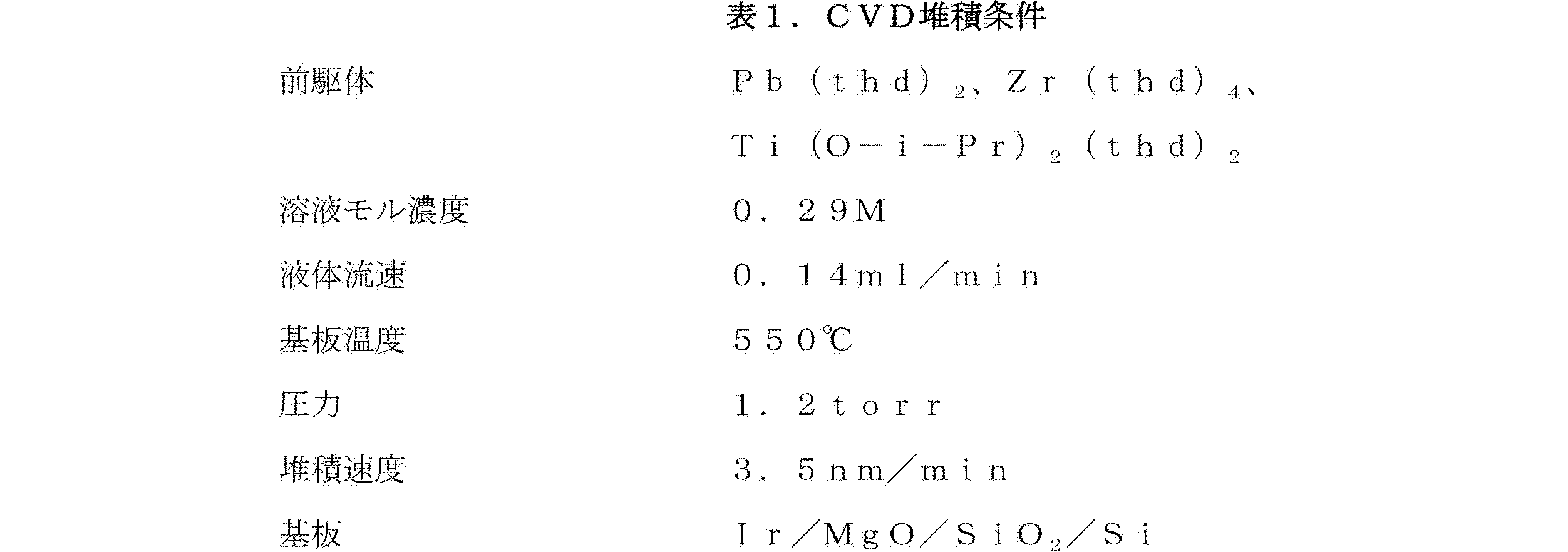
以下のプロセス条件が適用された。
代表的なランでは、膜はIr/SiO2/Si上に565℃で堆積された。圧力は1.2Torrであり、酸化剤流は500sccmのO2と500sccmのN2Oの混合物であり、試薬流速は32.5分間の間0.14ml/minであった。XRF分析によって、結果として得られるPbZrTiO3膜について以下の厚さおよび組成データが得られた。 In a typical run, the film was deposited at 565 ° C. on Ir / SiO 2 / Si. The pressure was 1.2 Torr, the oxidant flow was a mixture of 500 sccm O 2 and 500 sccm N 2 O, and the reagent flow rate was 0.14 ml / min for 32.5 minutes. The following thickness and composition data were obtained for the resulting PbZrTiO 3 film by XRF analysis.
![]()
![]()
例2
様々なPb/(Zr+Ti)比を有する溶液を、一連の堆積ランに用いた。この比率は、以下、(A/B)gとして定義され、これは、ペロブスカイトセル、ABO3における、Pbの「A」部位への、および、ZrならびにTiそれぞれの「B」部位への従来の割当てを示す。下付き文字gは反応チャンバにおける気相濃度を示し、その一方で(A/B)fは膜における当量比を示す。
Example 2
Solutions with various Pb / (Zr + Ti) ratios were used for a series of deposition runs. This ratio is hereinafter defined as (A / B) g , which is the conventional ratio of Pb to the “A” site and to the “B” site of Zr and Ti, respectively, in the perovskite cell, ABO 3 . Indicates assignment. The subscript g indicates the gas phase concentration in the reaction chamber, while (A / B) f indicates the equivalent ratio in the membrane.
Zr/(Zr+Ti)の気相比は0.612で一定に保たれた。例1において上述した条件下で、かつ、用いられた特定のCVD反応器に対して、Zr/(Zr+Ti)=0.612の気相比は、Zr/Tiが〜40/60である膜をもたらし、これは、バルク材では正方結晶構造および強誘電特性をもたらした。この気相比は、その高いPrと、低いZr/Ti比ではペロブスカイト相を形成することが比較的簡単であることによってFeRAM応用に選択される一般的な組成である。 The gas phase ratio of Zr / (Zr + Ti) was kept constant at 0.612. Under the conditions described above in Example 1 and for the particular CVD reactor used, a gas phase ratio of Zr / (Zr + Ti) = 0.612 results in a film with Zr / Ti of ˜40 / 60. This led to a tetragonal crystal structure and ferroelectric properties in the bulk material. This gas phase ratio is a common composition chosen for FeRAM applications due to its high Pr and the relatively simple formation of a perovskite phase at a low Zr / Ti ratio.
次に、一連のPZT膜が固定の堆積時間で、下記の表1に記載するプロセス条件下で堆積された。この実験に基づく研究において決められる(A/B)gの(A/B)fへの効果を図1に示す。公称膜厚は100nmであった。低(A/B)gでは、(A/B)fは気相の鉛のモル分率とともに単調に増加した。0.93<(A/B)g<1.53の範囲では、(A/B)fにおいて、1.10から1.15の範囲でプラトーが観察された。これらの膜については、ペロブスカイト相は存在する唯一の結晶相であった。 A series of PZT films were then deposited under the process conditions described in Table 1 below with a fixed deposition time. The effect of (A / B) g on (A / B) f determined in the study based on this experiment is shown in FIG. The nominal film thickness was 100 nm. At low (A / B) g , (A / B) f increased monotonically with the molar fraction of lead in the gas phase. In the range of 0.93 <(A / B) g <1.53, a plateau was observed in the range of 1.10 to 1.15 in (A / B) f . For these films, the perovskite phase was the only crystalline phase present.
膜組成が気相のPbの組成変化に対して反応しないこのプロセスウィンドウの出現は、2つの競合プロセス、すなわち、Pb、Zr、およびTi前駆体の分解を介するペロブスカイトPZTの形成、および、成長表面からの余剰PbOの脱着の観点から理論的に説明される。このプロセスウィンドウを説明するにあたって任意の理論または機構に制約されることを望まないが、バルクPZTの場合のように、PZT上のPbOの蒸気圧は固体のPbOに対する蒸気圧よりかなり低いと仮定される(K.H. HartlおよびH. Rau、Solid
State Comm.、7、41(1969)にまとめられているバルクPZT材料特性を参照)。
The emergence of this process window where the film composition does not react to changes in the composition of gas phase Pb is due to two competing processes: the formation of perovskite PZT via the decomposition of Pb, Zr and Ti precursors, and the growth surface This is theoretically explained from the viewpoint of desorption of excess PbO. While not wishing to be bound by any theory or mechanism in describing this process window, it is assumed that the vapor pressure of PbO on PZT is much lower than the vapor pressure for solid PbO, as in bulk PZT. (KH Hartl and H. Rau, Solid
(See bulk PZT material properties summarized in State Comm., 7, 41 (1969)).
PZT形成の反応速度が速く、また、PbO揮発性が高い処理条件下では、単相の化学量論的PZTを形成することができる。 Single phase stoichiometric PZT can be formed under processing conditions where the reaction rate of PZT formation is high and PbO volatility is high.
1.00を超える(A/B)f値におけるプラトーの存在は、XRF測定の不正確さによって、または、下部電極内への拡散される余剰のPbによって影響を受けることがある。金属成分の取り込み効率の分析によって、(A/B)g>0.83ではPb効率が下がり、その一方でZrおよびTi効率は、同じ範囲で略一定に維持されたことが示された。このことは、プラトーの出現と、膜のXRD分析からのPbOの不在と一貫している。(A/B)gが増加されると、膜厚は僅かに減少した。このことは、3.8から3.2nm/minに減少する近似成長速度に対応する。 The presence of a plateau at an (A / B) f value greater than 1.00 can be affected by inaccuracies in the XRF measurement or by extra Pb diffused into the bottom electrode. Analysis of metal component uptake efficiency showed that Pb efficiency decreased at (A / B) g > 0.83, while Zr and Ti efficiencies remained approximately constant in the same range. This is consistent with the appearance of a plateau and the absence of PbO from the XRD analysis of the membrane. (A / B) When g was increased, the film thickness decreased slightly. This corresponds to an approximate growth rate that decreases from 3.8 to 3.2 nm / min.
上述したように堆積された膜は、すべて滑らかで密度が高く、粒子が細かい。これらのイメージから計算されたラフネスおよび粒径の値を、下記の表2に記載する。測定された膜ラフネスは、気相組成に反応せず、また、基板として用いられるIr膜の開始表面ラフネスの約2倍であった。 The films deposited as described above are all smooth, dense, and fine particles. The roughness and particle size values calculated from these images are listed in Table 2 below. The measured film roughness did not react to the gas phase composition and was about twice the starting surface roughness of the Ir film used as the substrate.
(A/B)gが増加されると、粒子サイズがファセッティングの範囲と同じように増加し、このことは、表面移動度が高められたことを示唆する。これは、上述した成長モデルが有効であるならば高い気相Pb濃度での成長中に高いPbO表面被覆率がなくてはならない結果であると考えられている。高Pbサンプルでのファセッティングは、PZT(001)配向の存在を示す主に正方形の特徴が明らかとなり、X線回折結果によっても結果は支持された。 As (A / B) g is increased, the particle size increases in the same way as the faceting range, suggesting that the surface mobility is increased. This is believed to be a result of having a high PbO surface coverage during growth at high vapor phase Pb concentrations if the growth model described above is valid. Faceting with high Pb samples revealed a predominantly square feature indicating the presence of PZT (001) orientation, and the results were supported by X-ray diffraction results.
X線回折分析によって、(A/B)g >0.83で堆積された膜については単ペロブスカイト相が明らかとなった。(A/B)g<0.83では、2Θ=29.9°において追加のピークが観察された。このピークの強度は(A/B)gが増加すると減少し、鉛が不足した堆積条件下での望ましくないパイロクロア相の形成に因るものである。 X-ray diffraction analysis revealed a single perovskite phase for films deposited with (A / B) g > 0.83. For (A / B) g <0.83, an additional peak was observed at 2Θ = 29.9 °. The intensity of this peak decreases with increasing (A / B) g and is attributed to the formation of undesirable pyrochlore phases under lead-poor deposition conditions.
Ir/MgO上のPZT膜は、支配的な(001)および(101)PZT配向を示した。さらに、PZTピーク強度の(001)/(101)比は、(A/B)gの増加と共に増加した。すなわち、0.406nmのc軸格子定数を有する正方晶c軸に向かって配向された。Ir/MgO上では検知できるほどの(111)PZT組織は観察されなかった。受取った状態の(as-received)基板のX線回折によって、主に(111)配向されたIrが明らかとなった。しかし、多量の(200)Irピークが存在した。 PZT films on Ir / MgO showed dominant (001) and (101) PZT orientations. Furthermore, the (001) / (101) ratio of PZT peak intensity increased with increasing (A / B) g . That is, it was oriented toward a tetragonal c-axis having a c-axis lattice constant of 0.406 nm. No detectable (111) PZT structure was observed on Ir / MgO. X-ray diffraction of the as-received substrate revealed mainly (111) oriented Ir. However, there was a large amount of (200) Ir peak.
最良の電気特性は、図1に示す曲線のニーの直ぐ上の(A/B)gを有する膜に対して見出された。もっと高いまたはもっと低い(A/B)gを有する膜では電気的に短絡してしまった。3Vの動作では、(A/B)g=0.93で堆積された150nmの厚さを有する膜では、残留分極(2Pr)および抗電圧(Vc)が、それぞれ、85μC/cm2および0.77Vであると測定された。残留分極のこの高い値は、強い優先(001)配向と、Ir基板において得られる高度の結晶化に因るものである。 The best electrical properties were found for films with (A / B) g just above the knee of the curve shown in FIG. Films with higher or lower (A / B) g were electrically shorted. For 3 V operation, for a film with a thickness of 150 nm deposited with (A / B) g = 0.93, the remanent polarization (2P r ) and coercive voltage (V c ) are 85 μC / cm 2 and It was measured to be 0.77V. This high value of remanent polarization is due to the strong preferential (001) orientation and the high degree of crystallization obtained in Ir substrates.
例3
中央複合計画(central-composite-design)実験を用いて大きい容量のプロセス空間を調べ、主たるプロセス変数間の相互作用を評価した。堆積温度(550、575、600℃)および圧力(500、1750、3000mTorr)を、5つの異なる(A/B)g値(0.53、0.73、0.93、1.13、1.53)において独立して変化させた。1660秒の一定堆積時間を用いた。
Example 3
A large-capacity process space was investigated using a central-composite-design experiment to evaluate the interaction between the main process variables. Deposition temperature (550, 575, 600 ° C.) and pressure (500, 1750, 3000 mTorr), five different (A / B) g values (0.53, 0.73, 0.93, 1.13, 1. 53) was changed independently. A constant deposition time of 1660 seconds was used.
組成的には、(A/B)fにおけるプラトーの始まりは、(A/B)g=0.93において観察された。所与の圧力では、膜の鉛含有量は、堆積温度が増加すると減少することが観察された。さらに、鉛とチタンの取り込み効率は、すべての温度について、(A/B)gが増加すると減少した。 Compositionally, the onset of a plateau at (A / B) f was observed at (A / B) g = 0.93. It was observed that at a given pressure, the lead content of the film decreases with increasing deposition temperature. In addition, lead and titanium uptake efficiency decreased with increasing (A / B) g for all temperatures.
電気的には、最良のサンプルは、計画の中心(575℃、1.75Torr、(A/B)g〜1)における条件からもたらされた。良好なサンプルの多くは(−)電圧オフセットを示した。検知できるほどの中心から端への(Center-to-edge)(ウェーハ)効果はなかった。漏れの挙動は、低いPbおよび厚いサンプル(〜2.5Vまでで〜130nm)において良好であるようであった。 Electrically, the best sample resulted from conditions at the center of the plan (575 ° C., 1.75 Torr, (A / B) g −1). Many of the good samples showed a (−) voltage offset. There was no detectable center-to-edge (wafer) effect. Leakage behavior appeared to be good for low Pb and thick samples (˜130 nm up to ~ 2.5V).
例4
代替の酸化ジルコニウム前駆体が必要となり、これらは、Zr(thd)4よりも揮発性が高く、またさらに、例えばPb(thd)2の表面分解により適合するように低い熱安定性を有する。
Example 4
Alternative zirconium oxide precursors are required, these are more volatile than Zr (thd) 4 , and further have low thermal stability, eg, to better match the surface decomposition of Pb (thd) 2 .
図4は、Pb(thd)2、Ti(O−i−Pr)2,(thd)2、および2つの選択されたZr化合物、すなわち、Zr(thd)4およびZr(O−i−Pr)2(thd)2の比較TGAデータを示す。Zr(O−i−Pr)2(thd)2化合物は、400℃においてほぼ20%の望ましくない残留物含有量を有するが、MOCVD PZTに一般的に用いられるPbおよびTi化合物に合う望ましい熱安定性を有する。 FIG. 4 shows Pb (thd) 2 , Ti (Oi-Pr) 2 , (thd) 2 , and two selected Zr compounds, namely Zr (thd) 4 and Zr (Oi-Pr). 2 (thd) 2 shows comparative TGA data. Zr (Oi-Pr) 2 (thd) 2 compound has an undesirable residue content of almost 20% at 400 ° C., but desirable thermal stability to match Pb and Ti compounds commonly used in MOCVD PZT Have sex.
MOCVD PZT堆積が、200℃に設定された気化器温度で、新規のZr(O−i−Pr)2(thd)2(Zr−2−2)化合物を用いて標準的なIr/TiAlN下部電極(BE)上に行われた。追加の堆積が、203℃の気化器温度において、標準的なZr(thd)4(Zr−0−4)化合物を用いて処理された。他のすべての堆積条件は一定にされた。PZT堆積後、Pt上部電極(TE)が電子ビーム蒸発され、サンプルは、30分間の間、流動アルゴン中で650℃においてアニールされた。 MOCVD PZT deposition is a standard Ir / TiAlN bottom electrode using a novel Zr (Oi-Pr) 2 (thd) 2 (Zr-2-2) compound at a vaporizer temperature set at 200 ° C. (BE) was done on. Additional deposits were processed with standard Zr (thd) 4 (Zr-0-4) compounds at a vaporizer temperature of 203 ° C. All other deposition conditions were kept constant. After PZT deposition, the Pt top electrode (TE) was electron beam evaporated and the sample was annealed at 650 ° C. in flowing argon for 30 minutes.
Zr−2−2サンプルの組成および電気データを、Zr−0−2サンプルから収集されたデータと共に提示した。Zr−2−2サンプルは、PbおよびZr含有量はZr−0−4サンプルよりも感知できるほどに低いが、電気的に匹敵する。 The composition and electrical data for the Zr-2-2 sample was presented along with the data collected from the Zr-0-2 sample. The Zr-2-2 sample is electrically comparable, although the Pb and Zr content is appreciably lower than the Zr-0-4 sample.
Zr(O−i−Pr)2(thd)2前駆体に加えて、MOCVD PZTは、さらに別の新規のZr源前駆体を用いても作成されうる。例えば、Zr2(O−i−Pr)6(thd)2は、良好な周囲安定性、高い揮発性、および、PbおよびTi前駆体と最良の熱適合性を有する。 In addition to Zr (Oi-Pr) 2 (thd) 2 precursor, MOCVD PZT can also be made using yet another novel Zr source precursor. For example, Zr 2 (O-i- Pr) 6 (thd) 2 is better ambient stability, high volatility, and a Pb and Ti precursor and best thermal compatibility.
例5
本発明に従って形成されたPZT材料を用いて多数のサンプルが作成された。これらのサンプルは、スパッタリング技術によって下部電極を形成し、これらの電極上に本発明に従ってPZT材料を堆積し、その後、電子ビーム堆積によってシャドウマスクを介して上部電極を堆積することを含む。PZT堆積時間は、10nmから260nmの膜厚を目標に165秒から4065秒の間で変化させられた。
Example 5
A number of samples were made using PZT material formed in accordance with the present invention. These samples include forming lower electrodes by sputtering techniques, depositing PZT material according to the present invention over these electrodes, and then depositing the upper electrode through a shadow mask by electron beam deposition. The PZT deposition time was varied between 165 seconds and 4065 seconds with a target film thickness of 10 nm to 260 nm.
これらのサンプルの電気試験によって、厚さ、パルス長、および、本発明の強誘電性PZT材料の強誘電性分極、サイクル疲労等を含む面積スケーリング特性を立証するキャパシタ構造の電気的特徴が提供される。 Electrical testing of these samples provides capacitor structure electrical characteristics that demonstrate thickness, pulse length, and area scaling characteristics including ferroelectric polarization, cycle fatigue, etc. of the ferroelectric PZT material of the present invention. The
図5に、漏れ電流密度対電界を示す。77nmの膜に対する高い「漏れ」が直ぐに確認された。厚さ閾値未満の膜についての定性的に異なる電気的挙動は、高い相対ラフネス(ラフネス/厚さ)に因るものであってよく、これは、薄い膜において非常に薄い領域がもたらされる。このような場合、局所的に高い電界が予期される。セット(>77nm)のうちのより厚い膜に対する電流密度は、際立って安定した電界依存性が示された。両極性における漏れは、150kV/cmに対して10−6〜10−7A/cm2の範囲であった(150kV/cmは、例えば、125nmの膜では1.9Vに対応する)。 FIG. 5 shows leakage current density versus electric field. A high “leak” for the 77 nm film was immediately identified. The qualitatively different electrical behavior for films below the thickness threshold may be due to high relative roughness (roughness / thickness), which results in very thin regions in the thin film. In such a case, a locally high electric field is expected. The current density for the thicker films of the set (> 77 nm) showed a markedly stable electric field dependence. The leakage in both polarities was in the range of 10 −6 to 10 −7 A / cm 2 for 150 kV / cm (150 kV / cm corresponds to, for example, 1.9 V for a 125 nm film).
漏れは、電界の関数としてプロットされた場合に、厚さに反応しない4つの特性のうちの1つであった。他の特性は、抗電圧(Vc)、分極飽和(PSW対VOP)、および疲労耐性であった。 Leakage was one of four characteristics that did not respond to thickness when plotted as a function of electric field. Other properties were coercive voltage (V c ), polarization saturation ( PSW vs. V OP ), and fatigue resistance.
各サンプルに対する抗電圧は、関係3Vc(測定済み)=Vopから決定され、その方法に基づくEcの計算された値を図6に示す。厚さが77nmより大きいPZT膜については、Ecは約50kV/cmであった。
The coercive voltage for each sample was determined from the
パルス測定を用いて分極飽和を調べた。図7は、電圧および電界への反転分極の依存を示す。データは、高い電圧に対しては分極が増加することが予期されることを示す。高い電界に耐えることのできる厚い膜について明らかな飽和挙動が観察される。125nmまたはそれよりも厚い膜では、飽和PSW>40μC/cm2である。飽和に近いPSW(300kV/cm)に正規化されて、PSW対Eは、膜厚とほぼ無関係となる。すべてのサンプルで、PSWは、3Ec(〜150kV/cm)においてその最大値の約90%に到達する。 Polarization saturation was investigated using pulse measurements. FIG. 7 shows the dependence of inversion polarization on voltage and electric field. The data show that polarization is expected to increase for higher voltages. Obvious saturation behavior is observed for thick films that can withstand high electric fields. For films of 125 nm or thicker, saturation P SW > 40 μC / cm 2 . Normalized to P SW (300 kV / cm) close to saturation, P SW pair E becomes almost independent of film thickness. In all samples, P SW reaches about 90% of its maximum at 3E c (˜150 kV / cm).
このサンプルセットの疲労特性も、電界スケーリングについて安定した特性を示した(図8)。疲労測定は、3Ecに対応する150kV/cmにおいて行われた。疲労波形は、10−5秒の期間を有する方形波であった。疲労は、PZT厚さにほぼ無関係で、109回のサイクルにおいて〜50%でPSWが減少する。 The fatigue characteristics of this sample set also showed stable characteristics with respect to electric field scaling (FIG. 8). Fatigue measurements were made at 150 kV / cm corresponding to 3E c. The fatigue waveform was a square wave with a period of 10 −5 seconds. Fatigue is substantially independent of the PZT thickness, P SW is reduced by 50% at 10 9 cycles.
スタティックインプリントが、抗電圧における非対称性として現れ、[Vc(−)+Vc(+)]/2として定義される。インプリント電圧が、単一キャパシタの反復測定、ポーリング、およびアニーリングを介して調べられた。時間=0におけるVc(+および−)の初期測定の後、キャパシタは2.5Vとなるよう正極または負極に調整され、次に、20分間の間150℃(空気)においてアニーリングされた。冷却後、その同じ(極性が調整された)キャパシタが再測定された。24分(すなわち、45分の経過時間)および45分(90分の経過時間)のアニールの後、追加の測定が繰り返された。 A static imprint appears as an asymmetry in coercive voltage and is defined as [V c (−) + V c (+)] / 2. The imprint voltage was examined through single capacitor repeated measurements, polling, and annealing. After initial measurement of V c (+ and −) at time = 0, the capacitor was adjusted to the positive or negative electrode to 2.5 V and then annealed at 150 ° C. (air) for 20 minutes. After cooling, the same (polarity adjusted) capacitor was remeasured. Additional measurements were repeated after 24 minutes (ie 45 minutes elapsed time) and 45 minutes (90 minutes elapsed time) annealing.
図9は、インプリント電圧対時間の半対数のプロットを示す。サンプルは、時間=0において略同一のインプリント(〜−0.1V)を有した。インプリントは、20分における第1の測定の少し前にかなり増加することが明らかである。薄い膜は、厚い膜よりも低いインプリント速度を有することが観察された。この傾向は、インプリント電界の観点からデータを分析することを提案する。 FIG. 9 shows a semi-log plot of imprint voltage versus time. The sample had approximately the same imprint (˜−0.1 V) at time = 0. It is clear that the imprint increases considerably shortly before the first measurement at 20 minutes. Thin films were observed to have a lower imprint rate than thick films. This trend suggests analyzing the data in terms of the imprint electric field.
例6
強誘電性材料の開発の際の試験機器およびサンプル作成を簡略化するために、電気的試験は、約1mSのパルス幅と、約104μm2のキャパシタ面積を用いて従来から行われている。この試験レジメンの欠点は、デバイスに適したスケール(すなわち、25nSパルスおよび102μm2)で電気特性の実行可能性(viability)を示すことができないことである。市場の傾向は、ますます短くなっている時間スケールで、より小さいキャパシタ面積で動作するデバイスに向かっているので、スケーリングの問題は将来のデバイスの成功には重要である。
Example 6
In order to simplify the test equipment and sample preparation during the development of ferroelectric materials, electrical testing is conventionally performed using a pulse width of about 1 mS and a capacitor area of about 10 4 μm 2 . . The disadvantage of this test regimen is that it cannot show the viability of electrical properties at a scale appropriate for the device (
これらの測定に用いたサンプルは、プロセスセットAに記載したように、Irの下部電極、標準PZT、および、40nmのIrO2および60nmのIrから構成される上部電極を有する直径6インチのSiウェーハからもたらされた。個々のキャパシタは、パターン付きフォトレジストおよびCl2/Ar/O2混合物における反応性エッチングを用いて画定された。パターニング後、サンプルは、30分間の間、流動酸素中で650℃においてアニールされた。 The sample used for these measurements was a 6 inch diameter Si wafer with an Ir bottom electrode, standard PZT, and a top electrode composed of 40 nm IrO 2 and 60 nm Ir as described in Process Set A. Brought from. Individual capacitor defined by using a reactive etching in the patterned photoresist and Cl 2 / Ar / O 2 mixture. After patterning, the samples were annealed at 650 ° C. in flowing oxygen for 30 minutes.
図10に示すように、試験システムは、SRS DS345任意波形ジェネレータ、テクトロニクス(Tektronix)620Bデジタルストレージオシロスコープ、およびシャントレジスタから構成される。この試験プロトコルの詳細は、P.K. Larsen、G. Kampschoer、M. Ulenaers、G. Spierings、およびR. Cuppens、Applied Physics Letters、Vol. 59、Issue 5、611-613頁(1991)に記載される。標準方形パルス強誘電性パルス列が用いられた。このパルス列は、1つの負極性パルスと、続いて2つの正パルスと、2つの負パルス(設定、正、上、負、下)から構成される。図10の位置Xにおいて測定された一般的な駆動信号および図10の位置Yにおいて測定された応答信号を、図11に示す。
As shown in FIG. 10, the test system consists of an SRS DS345 arbitrary waveform generator, a Tektronix 620B digital storage oscilloscope, and a shunt register. Details of this test protocol are described in P.K. Larsen, G. Kampschoer, M. Ulenaers, G. Spierings, and R. Cuppens, Applied Physics Letters, Vol. 59,
各応答パルスにおいて強誘電体キャパシタから接地に通る総電荷は、次式から計算することができる。
電荷:Q=(1/RS)∫VdV
The total charge passing from the ferroelectric capacitor to ground in each response pulse can be calculated from:
Charge: Q = (1 / R S ) ∫VdV
強誘電反転は、負(正)パルスによって前に極性が与えられていた強誘電体キャパシタが、後続の正(負)パルスによって極性が上げられる(下げられる)と起きる。QSWは、反転パルスおよび非反転パルスにおいて含まれる総電荷における差として定義される。すなわち、
QSW=(S0+S1)−(P0+P1)
ここで、S0およびS1は、第1反転パルスの立ち上がり応答パルスおよび立ち下り応答パルスであり、P0およびP1は、第1の非反転パルスの立ち上がりパルスおよび立ち下がりパルスである(図11)。
Ferroelectric inversion occurs when a ferroelectric capacitor that was previously given polarity by a negative (positive) pulse is raised (decreased) by a subsequent positive (negative) pulse. Q SW is defined as the difference in the total charge contained in the inverted and non-inverted pulses. That is,
Q SW = (S 0 + S 1 ) − (P 0 + P 1 )
Here, S 0 and S 1 are a rising response pulse and a falling response pulse of the first inversion pulse, and P 0 and P 1 are a rising pulse and a falling pulse of the first non-inversion pulse (FIG. 11).
1、2、および3Vパルスと、25nSと0.22mSの間のパルス長で、上述したように測定を行った。分極は、調べた範囲に亘ってパルス長と無関係であることが分かった(図12)。 Measurements were performed as described above with 1, 2, and 3 V pulses and pulse lengths between 25 nS and 0.22 mS. Polarization was found to be independent of pulse length over the range examined (FIG. 12).
さらに、1μSパルスと、33μm×33μmから4μm×4μmの正方形のキャパシタを用いて面積スケーリングを調べた。QSWも、調べた範囲に亘ってキャパシタ寸法と無関係であることが分かった(図13)。 Furthermore, the area scaling was examined using a 1 μS pulse and a square capacitor of 33 μm × 33 μm to 4 μm × 4 μm. Q SW was also found to be independent of capacitor size over the range examined (FIG. 13).
産業上の利用可能性
本発明のPZT材料は、集積回路メモリにおいて有用に採用される。そのスケーラビリティ(寸法的にスケーラブルである、および/または、特徴において電界スケーラブルである)によって、この材料は、例えば約20ナノメートルから約150ナノメートルである広い厚さ範囲、および、0.15μmまで低く延在する横寸法の範囲に亘って、例えばFeRAMである強誘電性薄膜キャパシタ構造における使用に特に適している。本発明のPZT材料は、アクセプタドーピングまたは膜改質剤(例えば、Nb、Ta、La、Sr、Ca等)の使用といったPZT膜改質技術を用いることなく、液体供給MOCVDによって容易に形成されうる。
Industrial Applicability The PZT material of the present invention is usefully employed in integrated circuit memories. Due to its scalability (dimensionally scalable and / or electric field scalable in character), this material has a wide thickness range, for example from about 20 nanometers to about 150 nanometers, and up to 0.15 μm Over a range of lateral dimensions extending low, it is particularly suitable for use in ferroelectric thin film capacitor structures, for example FeRAM. The PZT material of the present invention can be easily formed by liquid supply MOCVD without using PZT film modification techniques such as acceptor doping or use of film modifiers (eg, Nb, Ta, La, Sr, Ca, etc.). .
Claims (13)
前記鉛、ジルコニウム及びチタンの前駆体が、リガンド交換を受けておらず、
前記溶媒媒体がオクタン、デカン及びポリアミンを含み、
前記前駆体がPb(thd)2pmdeta、Zr(iOPr)2(thd)2、及びTi(iOPr)2(thd)2を含む、
液体前駆体溶液の混合液。 A liquid precursor solution mixture containing lead, zirconium and titanium precursors dissolved or suspended in a solvent medium,
The lead, zirconium and titanium precursors have not undergone ligand exchange,
The solvent medium comprises octane, decane and polyamine;
The precursor comprises Pb (thd) 2 pmdata, Zr (iOPr) 2 (thd) 2 , and Ti (iOPr) 2 (thd) 2 ;
Liquid precursor solution mixture.
請求項1に記載の液体前駆体溶液の混合液。 The solvent medium comprises octane, decane and polyamine in a ratio of 5: 4: 1;
A liquid mixture of the liquid precursor solution according to claim 1.
請求項1に記載の液体前駆体溶液の混合液。 The mixture is evaporated;
A liquid mixture of the liquid precursor solution according to claim 1.
請求項1に記載の液体前駆体溶液の混合液。 The mixed solution is evaporated so as to realize a gas phase composition that is the same as the composition ratio of the mixed solution of the liquid precursor solution.
A liquid mixture of the liquid precursor solution according to claim 1.
(但し、A/B比はPb/(Zr+Ti)である)
請求項1に記載の液体前駆体溶液の混合液。 Having an A / B ratio of 0.612 to 1.53,
(However, the A / B ratio is Pb / (Zr + Ti))
A liquid mixture of the liquid precursor solution according to claim 1.
前記鉛、ジルコニウム及びチタンの前駆体が、リガンド交換を受けておらず、
前記前駆体組成物がオクタン、デカン及びポリアミンを含み、
前記前駆体がPb(thd)2pmdeta、Zr(iOPr)2(thd)2、及びTi(iOPr)2(thd)2を含む、
前駆体蒸気組成物。 A precursor vapor composition comprising precursors of lead, zirconium and titanium,
The lead, zirconium and titanium precursors have not undergone ligand exchange,
The precursor composition comprises octane, decane and polyamine;
The precursor comprises Pb (thd) 2 pmdata, Zr (iOPr) 2 (thd) 2 , and Ti (iOPr) 2 (thd) 2 ;
Precursor vapor composition.
請求項6に記載の前駆体蒸気組成物。 Containing octane, decane and polyamine in a ratio of 5: 4: 1;
The precursor vapor composition of claim 6.
(但し、A/B比はPb/(Zr+Ti)である)
請求項6に記載の前駆体蒸気組成物。 Having an A / B ratio of 0.612 to 1.53,
(However, the A / B ratio is Pb / (Zr + Ti))
The precursor vapor composition of claim 6.
請求項6に記載の前駆体蒸気組成物。 Used to produce a ferroelectric PZT film on a substrate;
The precursor vapor composition of claim 6.
請求項6に記載の前駆体蒸気組成物。 Having a temperature of 1 00 ° C. or found 3 00 ° C.,
The precursor vapor composition of claim 6.
請求項6に記載の前駆体蒸気組成物。 Containing a carrier gas selected from the group consisting of Ar, N 2 , H 2 , He and NH 3 ;
The precursor vapor composition of claim 6.
請求項6に記載の前駆体蒸気組成物。 An oxidizing co-reaction gas selected from the group consisting of O 2 , N 2 O, O 3 and mixtures thereof,
The precursor vapor composition of claim 6.
請求項6に記載の前駆体蒸気組成物。 0 . Having a pressure in the range of 1 or al 7 60 torr,
The precursor vapor composition of claim 6.
Applications Claiming Priority (2)
| Application Number | Priority Date | Filing Date | Title |
|---|---|---|---|
| US09/251,890 US6316797B1 (en) | 1999-02-19 | 1999-02-19 | Scalable lead zirconium titanate(PZT) thin film material and deposition method, and ferroelectric memory device structures comprising such thin film material |
| US09/251,890 | 1999-02-19 |
Related Parent Applications (1)
| Application Number | Title | Priority Date | Filing Date |
|---|---|---|---|
| JP2000600296A Division JP2003517703A (en) | 1999-02-19 | 2000-02-18 | Scalable lead zirconate titanate (PZT) thin film materials and deposition methods, and ferroelectric storage device structures including such thin film materials |
Related Child Applications (2)
| Application Number | Title | Priority Date | Filing Date |
|---|---|---|---|
| JP2013125829A Division JP2013243133A (en) | 1999-02-19 | 2013-06-14 | FERROELECTRIC PZT MATERIAL, CAPACITOR, MICRO ELECTRONIC DEVICE STRUCTURE, AND FeRAM DEVICE |
| JP2013125830A Division JP5797230B2 (en) | 1999-02-19 | 2013-06-14 | Precursor composition, mixed solution of precursor solution, precursor vapor, method of supplying precursor composition, and method of forming lead zirconate titanate (PZT) film |
Publications (2)
| Publication Number | Publication Date |
|---|---|
| JP2013145745A JP2013145745A (en) | 2013-07-25 |
| JP5329709B2 true JP5329709B2 (en) | 2013-10-30 |
Family
ID=22953832
Family Applications (5)
| Application Number | Title | Priority Date | Filing Date |
|---|---|---|---|
| JP2000600296A Pending JP2003517703A (en) | 1999-02-19 | 2000-02-18 | Scalable lead zirconate titanate (PZT) thin film materials and deposition methods, and ferroelectric storage device structures including such thin film materials |
| JP2012278476A Expired - Fee Related JP5329709B2 (en) | 1999-02-19 | 2012-12-20 | Liquid precursor solution mixture and precursor vapor composition |
| JP2013125830A Expired - Fee Related JP5797230B2 (en) | 1999-02-19 | 2013-06-14 | Precursor composition, mixed solution of precursor solution, precursor vapor, method of supplying precursor composition, and method of forming lead zirconate titanate (PZT) film |
| JP2013125829A Pending JP2013243133A (en) | 1999-02-19 | 2013-06-14 | FERROELECTRIC PZT MATERIAL, CAPACITOR, MICRO ELECTRONIC DEVICE STRUCTURE, AND FeRAM DEVICE |
| JP2015201730A Expired - Lifetime JP6141380B2 (en) | 1999-02-19 | 2015-10-13 | Ferroelectric PZT film and method for manufacturing the same, capacitor, and FeRAM device |
Family Applications Before (1)
| Application Number | Title | Priority Date | Filing Date |
|---|---|---|---|
| JP2000600296A Pending JP2003517703A (en) | 1999-02-19 | 2000-02-18 | Scalable lead zirconate titanate (PZT) thin film materials and deposition methods, and ferroelectric storage device structures including such thin film materials |
Family Applications After (3)
| Application Number | Title | Priority Date | Filing Date |
|---|---|---|---|
| JP2013125830A Expired - Fee Related JP5797230B2 (en) | 1999-02-19 | 2013-06-14 | Precursor composition, mixed solution of precursor solution, precursor vapor, method of supplying precursor composition, and method of forming lead zirconate titanate (PZT) film |
| JP2013125829A Pending JP2013243133A (en) | 1999-02-19 | 2013-06-14 | FERROELECTRIC PZT MATERIAL, CAPACITOR, MICRO ELECTRONIC DEVICE STRUCTURE, AND FeRAM DEVICE |
| JP2015201730A Expired - Lifetime JP6141380B2 (en) | 1999-02-19 | 2015-10-13 | Ferroelectric PZT film and method for manufacturing the same, capacitor, and FeRAM device |
Country Status (5)
| Country | Link |
|---|---|
| US (7) | US6316797B1 (en) |
| EP (1) | EP1183719A4 (en) |
| JP (5) | JP2003517703A (en) |
| KR (1) | KR100702925B1 (en) |
| WO (1) | WO2000049646A1 (en) |
Families Citing this family (59)
| Publication number | Priority date | Publication date | Assignee | Title |
|---|---|---|---|---|
| US6316797B1 (en) * | 1999-02-19 | 2001-11-13 | Advanced Technology Materials, Inc. | Scalable lead zirconium titanate(PZT) thin film material and deposition method, and ferroelectric memory device structures comprising such thin film material |
| US6590243B2 (en) * | 1999-04-28 | 2003-07-08 | Sharp Laboratories Of America, Inc. | Ferroelastic lead germanate thin film and deposition method |
| US7094284B2 (en) * | 1999-10-07 | 2006-08-22 | Advanced Technology Materials, Inc. | Source reagent compositions for CVD formation of high dielectric constant and ferroelectric metal oxide thin films and method of using same |
| JP5290488B2 (en) | 2000-09-28 | 2013-09-18 | プレジデント アンド フェロウズ オブ ハーバード カレッジ | Vapor growth of oxides, silicates and phosphates |
| DE10050076C2 (en) * | 2000-10-10 | 2003-09-18 | Infineon Technologies Ag | Method for producing a ferromagnetic structure and ferromagnetic component |
| US6887716B2 (en) * | 2000-12-20 | 2005-05-03 | Fujitsu Limited | Process for producing high quality PZT films for ferroelectric memory integrated circuits |
| US6503763B2 (en) * | 2001-03-27 | 2003-01-07 | Sharp Laboratories Of America, Inc. | Method of making MFMOS capacitors with high dielectric constant materials |
| US6730354B2 (en) | 2001-08-08 | 2004-05-04 | Agilent Technologies, Inc. | Forming ferroelectric Pb(Zr,Ti)O3 films |
| US6528386B1 (en) | 2001-12-20 | 2003-03-04 | Texas Instruments Incorporated | Protection of tungsten alignment mark for FeRAM processing |
| US6635498B2 (en) | 2001-12-20 | 2003-10-21 | Texas Instruments Incorporated | Method of patterning a FeRAM capacitor with a sidewall during bottom electrode etch |
| US6596547B2 (en) | 2001-12-21 | 2003-07-22 | Texas Instruments Incorporated | Methods of preventing reduction of IrOx during PZT formation by metalorganic chemical vapor deposition or other processing |
| US6635497B2 (en) | 2001-12-21 | 2003-10-21 | Texas Instruments Incorporated | Methods of preventing reduction of IrOx during PZT formation by metalorganic chemical vapor deposition or other processing |
| US6686236B2 (en) | 2001-12-21 | 2004-02-03 | Texas Instruments Incorporated | Methods of preventing reduction of IrOx during PZT formation by metalorganic chemical vapor deposition or other processing |
| US6528328B1 (en) | 2001-12-21 | 2003-03-04 | Texas Instruments Incorporated | Methods of preventing reduction of irox during PZT formation by metalorganic chemical vapor deposition or other processing |
| US6500678B1 (en) | 2001-12-21 | 2002-12-31 | Texas Instruments Incorporated | Methods of preventing reduction of IrOx during PZT formation by metalorganic chemical vapor deposition or other processing |
| US6767750B2 (en) | 2001-12-31 | 2004-07-27 | Texas Instruments Incorporated | Detection of AIOx ears for process control in FeRAM processing |
| US6773930B2 (en) * | 2001-12-31 | 2004-08-10 | Texas Instruments Incorporated | Method of forming an FeRAM capacitor having a bottom electrode diffusion barrier |
| US6713342B2 (en) * | 2001-12-31 | 2004-03-30 | Texas Instruments Incorporated | FeRAM sidewall diffusion barrier etch |
| US20030143853A1 (en) * | 2002-01-31 | 2003-07-31 | Celii Francis G. | FeRAM capacitor stack etch |
| US20040023416A1 (en) * | 2002-08-05 | 2004-02-05 | Gilbert Stephen R. | Method for forming a paraelectric semiconductor device |
| JP3894554B2 (en) * | 2002-08-07 | 2007-03-22 | 松下電器産業株式会社 | Capacitor element and manufacturing method thereof |
| JP2004095638A (en) * | 2002-08-29 | 2004-03-25 | Fujitsu Ltd | Thin film decoupling capacitor and its manufacturing method |
| US6660612B1 (en) | 2002-11-07 | 2003-12-09 | Texas Instruments Incorporated | Design to prevent tungsten oxidation at contact alignment in FeRAM |
| JPWO2004066388A1 (en) * | 2003-01-17 | 2006-05-18 | 富士通株式会社 | Ferroelectric capacitor and manufacturing method thereof |
| US6998275B2 (en) | 2003-04-09 | 2006-02-14 | Texas Instruments Incorporated | Hydrogen-less CVD TiN process for FeRAM VIA0 barrier application |
| US6841396B2 (en) | 2003-05-19 | 2005-01-11 | Texas Instruments Incorporated | VIA0 etch process for FRAM integration |
| US20050019960A1 (en) * | 2003-07-25 | 2005-01-27 | Moon-Sook Lee | Method and apparatus for forming a ferroelectric layer |
| WO2005024950A1 (en) * | 2003-09-05 | 2005-03-17 | Fujitsu Limited | Semiconductor device and method for manufacturing same |
| US6872669B1 (en) | 2003-12-19 | 2005-03-29 | Texas Instruments Incorporated | PZT (111) texture through Ir texture improvement |
| US20050145908A1 (en) * | 2003-12-30 | 2005-07-07 | Moise Theodore S.Iv | High polarization ferroelectric capacitors for integrated circuits |
| JP2005251843A (en) * | 2004-03-02 | 2005-09-15 | Nec Electronics Corp | Semiconductor device, its manufacturing method, and storage device |
| JP4551725B2 (en) * | 2004-09-13 | 2010-09-29 | Okiセミコンダクタ株式会社 | Manufacturing method of semiconductor device |
| US20060073613A1 (en) * | 2004-09-29 | 2006-04-06 | Sanjeev Aggarwal | Ferroelectric memory cells and methods for fabricating ferroelectric memory cells and ferroelectric capacitors thereof |
| KR100667633B1 (en) * | 2004-12-20 | 2007-01-12 | 삼성전자주식회사 | Method of manufacturing a thin film layer, and method of manufacturing a gate structure, capacitor and flash memory device using the same |
| FR2881567A1 (en) * | 2005-02-01 | 2006-08-04 | Commissariat Energie Atomique | CAPACITOR WITH HIGH CLAMPING FIELD |
| KR100660550B1 (en) * | 2005-09-15 | 2006-12-22 | 삼성전자주식회사 | Method of forming ferroelcetric layer and ferroelectric capacitor |
| WO2007046173A1 (en) * | 2005-10-18 | 2007-04-26 | Murata Manufacturing Co., Ltd. | Thin film capacitor |
| WO2007116442A1 (en) * | 2006-03-30 | 2007-10-18 | Fujitsu Limited | Semiconductor device and method for fabricating the same |
| JP4438963B2 (en) * | 2006-11-29 | 2010-03-24 | セイコーエプソン株式会社 | Ferroelectric capacitor |
| JP5266632B2 (en) * | 2006-11-29 | 2013-08-21 | 富士通株式会社 | MIM element, electronic device, and method of manufacturing electronic device |
| US20110060165A1 (en) * | 2006-12-05 | 2011-03-10 | Advanced Technology Materials, Inc. | Metal aminotroponiminates, bis-oxazolinates and guanidinates |
| US20100112211A1 (en) * | 2007-04-12 | 2010-05-06 | Advanced Technology Materials, Inc. | Zirconium, hafnium, titanium, and silicon precursors for ald/cvd |
| WO2009012341A2 (en) * | 2007-07-16 | 2009-01-22 | Advancaed Technology Materials, Inc. | Group iv complexes as cvd and ald precursors for forming metal-containing thin films |
| US20090275164A1 (en) * | 2008-05-02 | 2009-11-05 | Advanced Technology Materials, Inc. | Bicyclic guanidinates and bridging diamides as cvd/ald precursors |
| DE102008035235B4 (en) * | 2008-07-29 | 2014-05-22 | Ivoclar Vivadent Ag | Device for heating molded parts, in particular dental ceramic molded parts |
| WO2010123531A1 (en) * | 2009-04-24 | 2010-10-28 | Advanced Technology Materials, Inc. | Zirconium precursors useful in atomic layer deposition of zirconium-containing films |
| US8088658B2 (en) * | 2009-04-28 | 2012-01-03 | E. I. Du Pont De Nemours And Company | Thin film capacitor and method of fabrication thereof |
| US7924547B1 (en) * | 2009-09-23 | 2011-04-12 | The United States Of America As Represented By The Secretary Of The Navy | RuO0.8 electrode and structure |
| JP2012256702A (en) * | 2011-06-08 | 2012-12-27 | Rohm Co Ltd | Ferroelectric capacitor |
| US8962350B2 (en) | 2013-02-11 | 2015-02-24 | Texas Instruments Incorporated | Multi-step deposition of ferroelectric dielectric material |
| US9305998B2 (en) | 2013-02-11 | 2016-04-05 | Texas Instruments Incorporated | Adhesion of ferroelectric material to underlying conductive capacitor plate |
| JP2015065277A (en) * | 2013-09-25 | 2015-04-09 | 株式会社アルバック | Method for manufacturing pzt thin film |
| US9153504B2 (en) * | 2013-10-11 | 2015-10-06 | Taiwan Semiconductor Manufacturing Company, Ltd. | Metal insulator metal capacitor and method for making the same |
| EP3154520B1 (en) * | 2014-06-13 | 2020-04-29 | HEIDELTEC GmbH | Matrix stabilized liposomes |
| JP6534036B2 (en) * | 2015-07-09 | 2019-06-26 | 国立大学法人金沢大学 | Field-effect transistor using hydrogen-terminated diamond |
| US9583336B1 (en) | 2016-02-18 | 2017-02-28 | Texas Instruments Incorporated | Process to enable ferroelectric layers on large area substrates |
| US11121139B2 (en) * | 2017-11-16 | 2021-09-14 | International Business Machines Corporation | Hafnium oxide and zirconium oxide based ferroelectric devices with textured iridium bottom electrodes |
| TWI773726B (en) * | 2018-01-18 | 2022-08-11 | 達興材料股份有限公司 | Fluorescent substance and method for producing the same |
| CN114956812B (en) * | 2022-05-24 | 2023-02-24 | 沈阳工业大学 | Lead titanate-lead zirconate nano composite film and preparation method thereof |
Family Cites Families (55)
| Publication number | Priority date | Publication date | Assignee | Title |
|---|---|---|---|---|
| US547855A (en) * | 1895-10-15 | William e | ||
| US3805195A (en) * | 1972-12-22 | 1974-04-16 | Rca Corp | Adaptive surface wave devices |
| US5453494A (en) | 1990-07-06 | 1995-09-26 | Advanced Technology Materials, Inc. | Metal complex source reagents for MOCVD |
| US5859274A (en) | 1997-10-30 | 1999-01-12 | Advanced Technology Materials, Inc. | Anhydrous mononuclear tris(β-diketonate) bismuth compositions for deposition of bismuth-containing films, and method of making the same |
| US7323581B1 (en) | 1990-07-06 | 2008-01-29 | Advanced Technology Materials, Inc. | Source reagent compositions and method for forming metal films on a substrate by chemical vapor deposition |
| US6110529A (en) | 1990-07-06 | 2000-08-29 | Advanced Tech Materials | Method of forming metal films on a substrate by chemical vapor deposition |
| US5204314A (en) * | 1990-07-06 | 1993-04-20 | Advanced Technology Materials, Inc. | Method for delivering an involatile reagent in vapor form to a CVD reactor |
| US5362328A (en) * | 1990-07-06 | 1994-11-08 | Advanced Technology Materials, Inc. | Apparatus and method for delivering reagents in vapor form to a CVD reactor, incorporating a cleaning subsystem |
| US5840897A (en) * | 1990-07-06 | 1998-11-24 | Advanced Technology Materials, Inc. | Metal complex source reagents for chemical vapor deposition |
| US5225561A (en) * | 1990-07-06 | 1993-07-06 | Advanced Technology Materials, Inc. | Source reagent compounds for MOCVD of refractory films containing group IIA elements |
| US6111124A (en) | 1997-10-30 | 2000-08-29 | Advanced Technology Materials, Inc. | Lewis base adducts of anhydrous mononuclear tris(β-diketonate) bismuth compositions for deposition of bismuth-containing films, and method of making the same |
| US5820664A (en) * | 1990-07-06 | 1998-10-13 | Advanced Technology Materials, Inc. | Precursor compositions for chemical vapor deposition, and ligand exchange resistant metal-organic precursor solutions comprising same |
| US5165960A (en) * | 1991-07-29 | 1992-11-24 | Ford Motor Company | Deposition of magnesium fluoride films |
| US5572052A (en) | 1992-07-24 | 1996-11-05 | Mitsubishi Denki Kabushiki Kaisha | Electronic device using zirconate titanate and barium titanate ferroelectrics in insulating layer |
| JP3383330B2 (en) * | 1992-09-22 | 2003-03-04 | 日本酸素株式会社 | Method for producing metal composite oxide film |
| GB2274456A (en) * | 1993-01-22 | 1994-07-27 | Timothy John Leedham | Volatile rare earth beta-diketone complexes |
| US5407855A (en) * | 1993-06-07 | 1995-04-18 | Motorola, Inc. | Process for forming a semiconductor device having a reducing/oxidizing conductive material |
| US5439840A (en) * | 1993-08-02 | 1995-08-08 | Motorola, Inc. | Method of forming a nonvolatile random access memory capacitor cell having a metal-oxide dielectric |
| JPH07142600A (en) * | 1993-11-12 | 1995-06-02 | Oki Electric Ind Co Ltd | Formation of thin film |
| US5555486A (en) * | 1994-12-29 | 1996-09-10 | North Carolina State University | Hybrid metal/metal oxide electrodes for ferroelectric capacitors |
| KR100360468B1 (en) * | 1995-03-20 | 2003-01-24 | 삼성전자 주식회사 | manufacturing method of ferroelectric film, capacator adopting the film and menufacturing method of the capacator |
| US6214105B1 (en) * | 1995-03-31 | 2001-04-10 | Advanced Technology Materials, Inc. | Alkane and polyamine solvent compositions for liquid delivery chemical vapor deposition |
| US6444264B2 (en) | 1995-03-31 | 2002-09-03 | Advanced Technology Materials, Inc. | Method for liquid delivery CVD utilizing alkane and polyamine solvent compositions |
| US5916359A (en) * | 1995-03-31 | 1999-06-29 | Advanced Technology Materials, Inc. | Alkane and polyamine solvent compositions for liquid delivery chemical vapor deposition |
| US6344079B1 (en) | 1995-03-31 | 2002-02-05 | Advanced Technology Materials, Inc. | Alkane and polyamine solvent compositions for liquid delivery chemical vapor deposition |
| JP3133922B2 (en) | 1995-06-09 | 2001-02-13 | シャープ株式会社 | Ferroelectric thin film coated substrate, method of manufacturing the same, and capacitor structure element |
| US5793076A (en) * | 1995-09-21 | 1998-08-11 | Micron Technology, Inc. | Scalable high dielectric constant capacitor |
| US5644184A (en) | 1996-02-15 | 1997-07-01 | Thermodyne, Inc. | Piezo-pyroelectric energy converter and method |
| JP3435966B2 (en) * | 1996-03-13 | 2003-08-11 | 株式会社日立製作所 | Ferroelectric element and method of manufacturing the same |
| TW345723B (en) * | 1996-07-09 | 1998-11-21 | Hitachi Ltd | Semiconductor memory and process for producing the same |
| US6303391B1 (en) | 1997-06-26 | 2001-10-16 | Advanced Technology Materials, Inc. | Low temperature chemical vapor deposition process for forming bismuth-containing ceramic films useful in ferroelectric memory devices |
| US5846275A (en) | 1996-12-31 | 1998-12-08 | Atmi Ecosys Corporation | Clog-resistant entry structure for introducing a particulate solids-containing and/or solids-forming gas stream to a gas processing system |
| US5935283A (en) | 1996-12-31 | 1999-08-10 | Atmi Ecosys Corporation | Clog-resistant entry structure for introducing a particulate solids-containing and/or solids-forming gas stream to a gas processing system |
| US6211034B1 (en) * | 1997-04-14 | 2001-04-03 | Texas Instruments Incorporated | Metal patterning with adhesive hardmask layer |
| JP4309477B2 (en) * | 1997-05-14 | 2009-08-05 | キネティック リミテッド | Chemical vapor deposition precursor |
| DE19730119A1 (en) * | 1997-07-14 | 1999-01-21 | Siemens Ag | Process for the production of thin films from oxidic ceramics |
| US5980893A (en) * | 1997-07-17 | 1999-11-09 | Beth Israel Deaconess Medical Center, Inc. | Agonist murine monoclonal antibody as a stimulant for megakaryocytopoiesis |
| US5959878A (en) * | 1997-09-15 | 1999-09-28 | Celis Semiconductor Corporation | Ferroelectric memory cell with shunted ferroelectric capacitor and method of making same |
| US6320213B1 (en) * | 1997-12-19 | 2001-11-20 | Advanced Technology Materials, Inc. | Diffusion barriers between noble metal electrodes and metallization layers, and integrated circuit and semiconductor devices comprising same |
| KR100275726B1 (en) * | 1997-12-31 | 2000-12-15 | 윤종용 | Ferroelectric memory device and fabrication method thereof |
| JP2002506996A (en) * | 1998-03-09 | 2002-03-05 | ティーワイシーオー エレクトロニクス ロジスティック エイジー | Ferrules to support some optical waveguides |
| JP2000236075A (en) * | 1999-02-12 | 2000-08-29 | Sony Corp | Manufacture of dielectric capacitor and manufacture of semiconductor memory |
| US6316797B1 (en) | 1999-02-19 | 2001-11-13 | Advanced Technology Materials, Inc. | Scalable lead zirconium titanate(PZT) thin film material and deposition method, and ferroelectric memory device structures comprising such thin film material |
| US7094284B2 (en) * | 1999-10-07 | 2006-08-22 | Advanced Technology Materials, Inc. | Source reagent compositions for CVD formation of high dielectric constant and ferroelectric metal oxide thin films and method of using same |
| US6730354B2 (en) * | 2001-08-08 | 2004-05-04 | Agilent Technologies, Inc. | Forming ferroelectric Pb(Zr,Ti)O3 films |
| ATE340800T1 (en) | 2001-10-26 | 2006-10-15 | Epichem Ltd | PRECURSOR COMPOUNDS FOR CHEMICAL VAPOR DEPOSITION |
| TW200411923A (en) | 2002-07-19 | 2004-07-01 | Asml Us Inc | In-situ formation of metal insulator metal capacitors |
| US7279392B2 (en) | 2003-08-04 | 2007-10-09 | Samsung Electronics Co., Ltd. | Thin film structure, capacitor, and methods for forming the same |
| US6844271B2 (en) | 2003-05-23 | 2005-01-18 | Air Products And Chemicals, Inc. | Process of CVD of Hf and Zr containing oxynitride films |
| US20050056219A1 (en) | 2003-09-16 | 2005-03-17 | Tokyo Electron Limited | Formation of a metal-containing film by sequential gas exposure in a batch type processing system |
| WO2007015436A1 (en) | 2005-08-04 | 2007-02-08 | Tosoh Corporation | Metal-containing compound, process for producing the same, metal-containing thin film, and method of forming the same |
| US7638645B2 (en) | 2006-06-28 | 2009-12-29 | President And Fellows Of Harvard University | Metal (IV) tetra-amidinate compounds and their use in vapor deposition |
| KR100807216B1 (en) | 2006-09-29 | 2008-02-28 | 삼성전자주식회사 | Apparatus and method of forming an thin layer having an improved thickness uniformity |
| US7964515B2 (en) | 2007-12-21 | 2011-06-21 | Tokyo Electron Limited | Method of forming high-dielectric constant films for semiconductor devices |
| US7816278B2 (en) | 2008-03-28 | 2010-10-19 | Tokyo Electron Limited | In-situ hybrid deposition of high dielectric constant films using atomic layer deposition and chemical vapor deposition |
-
1999
- 1999-02-19 US US09/251,890 patent/US6316797B1/en not_active Expired - Lifetime
-
2000
- 2000-02-18 EP EP00913553A patent/EP1183719A4/en not_active Ceased
- 2000-02-18 KR KR1020017010587A patent/KR100702925B1/en not_active IP Right Cessation
- 2000-02-18 JP JP2000600296A patent/JP2003517703A/en active Pending
- 2000-02-18 WO PCT/US2000/004371 patent/WO2000049646A1/en active IP Right Grant
-
2001
- 2001-08-13 US US09/928,860 patent/US6984417B2/en not_active Expired - Lifetime
-
2006
- 2006-01-10 US US11/328,582 patent/US7344589B2/en not_active Expired - Fee Related
-
2007
- 2007-10-26 US US11/924,716 patent/US7705382B2/en not_active Expired - Fee Related
-
2010
- 2010-04-27 US US12/768,374 patent/US7862857B2/en not_active Expired - Fee Related
- 2010-12-23 US US12/978,393 patent/US8501976B2/en not_active Expired - Fee Related
-
2012
- 2012-12-20 JP JP2012278476A patent/JP5329709B2/en not_active Expired - Fee Related
-
2013
- 2013-06-14 JP JP2013125830A patent/JP5797230B2/en not_active Expired - Fee Related
- 2013-06-14 JP JP2013125829A patent/JP2013243133A/en active Pending
- 2013-08-06 US US13/960,412 patent/US20130324390A1/en not_active Abandoned
-
2015
- 2015-10-13 JP JP2015201730A patent/JP6141380B2/en not_active Expired - Lifetime
Also Published As
| Publication number | Publication date |
|---|---|
| JP2013177697A (en) | 2013-09-09 |
| US8501976B2 (en) | 2013-08-06 |
| US20060115596A1 (en) | 2006-06-01 |
| JP2013243133A (en) | 2013-12-05 |
| KR20010109297A (en) | 2001-12-08 |
| WO2000049646A1 (en) | 2000-08-24 |
| US6316797B1 (en) | 2001-11-13 |
| US20110097478A1 (en) | 2011-04-28 |
| EP1183719A4 (en) | 2005-04-20 |
| US20130324390A1 (en) | 2013-12-05 |
| EP1183719A1 (en) | 2002-03-06 |
| JP5797230B2 (en) | 2015-10-21 |
| US6984417B2 (en) | 2006-01-10 |
| JP2016033262A (en) | 2016-03-10 |
| KR100702925B1 (en) | 2007-04-05 |
| US7862857B2 (en) | 2011-01-04 |
| US7344589B2 (en) | 2008-03-18 |
| US20100209596A1 (en) | 2010-08-19 |
| US20080049379A1 (en) | 2008-02-28 |
| JP6141380B2 (en) | 2017-06-07 |
| US20020014644A1 (en) | 2002-02-07 |
| US7705382B2 (en) | 2010-04-27 |
| JP2003517703A (en) | 2003-05-27 |
| JP2013145745A (en) | 2013-07-25 |
Similar Documents
| Publication | Publication Date | Title |
|---|---|---|
| JP6141380B2 (en) | Ferroelectric PZT film and method for manufacturing the same, capacitor, and FeRAM device | |
| JP2003517703A5 (en) | ||
| KR100629023B1 (en) | Titanium containing dielectric films and methods of forming same | |
| Yoshida et al. | Chemical vapor deposition of (Ba, Sr) TiO3 | |
| KR100371299B1 (en) | Epitaxially grown lead germanate film and deposition method | |
| KR100321178B1 (en) | Method of forming capacitor with TaON dielectic layer | |
| KR100398495B1 (en) | DEPOSITION AND ANNEALING OF MULTICOMPONENT ZrSnTi AND HfSnTi OXIDE THIN FILMS USING SOLVENTLESS LIQUID MIXTURE OF PRECURSORS | |
| JP4031552B2 (en) | Method for forming film of semiconductor device | |
| JP2001107238A (en) | Single phase perovskite ferroelectric film on platinum electrode, and method of its formation | |
| KR100395507B1 (en) | Semiconductor device and the method of fabricating same | |
| KR100282459B1 (en) | Manufacturing method of ferroelectric ram capacitor | |
| KR100438769B1 (en) | Method for forming metal oxide thin film of semiconductor device by cvd method and capacitor forming method using the same to embody high capacitance | |
| JPH09321234A (en) | Ferroelectric thin film device, manufacture thereof and ferroelectric memory device | |
| KR100882090B1 (en) | Method for fabricating capacitor of semiconductor device | |
| Seong et al. | Ferroelectric SrBi 2 Ta 2 O 9 thin film deposition at 550° C by plasma-enhanced metalorganic chemical vapor deposition onto a metalorganic chemical vapor deposition platinum bottom electrode | |
| Cho et al. | Low temperature MOCVD of BST thin film for high density DRAMs | |
| Ahn et al. | Magnetron Sputtering Technique | |
| JP2003174028A (en) | Manufacturing method for ferroelectric thin film, ferroelectric capacitor, and ferroelectric memory element |
Legal Events
| Date | Code | Title | Description |
|---|---|---|---|
| A521 | Request for written amendment filed |
Free format text: JAPANESE INTERMEDIATE CODE: A523 Effective date: 20130614 |
|
| TRDD | Decision of grant or rejection written | ||
| A01 | Written decision to grant a patent or to grant a registration (utility model) |
Free format text: JAPANESE INTERMEDIATE CODE: A01 Effective date: 20130704 |
|
| A61 | First payment of annual fees (during grant procedure) |
Free format text: JAPANESE INTERMEDIATE CODE: A61 Effective date: 20130724 |
|
| R150 | Certificate of patent or registration of utility model |
Ref document number: 5329709 Country of ref document: JP Free format text: JAPANESE INTERMEDIATE CODE: R150 Free format text: JAPANESE INTERMEDIATE CODE: R150 |
|
| S111 | Request for change of ownership or part of ownership |
Free format text: JAPANESE INTERMEDIATE CODE: R313111 |
|
| R350 | Written notification of registration of transfer |
Free format text: JAPANESE INTERMEDIATE CODE: R350 |
|
| R250 | Receipt of annual fees |
Free format text: JAPANESE INTERMEDIATE CODE: R250 |
|
| R250 | Receipt of annual fees |
Free format text: JAPANESE INTERMEDIATE CODE: R250 |
|
| R250 | Receipt of annual fees |
Free format text: JAPANESE INTERMEDIATE CODE: R250 |
|
| LAPS | Cancellation because of no payment of annual fees |