JP5325477B2 - Method for manufacturing semiconductor device - Google Patents
Method for manufacturing semiconductor device Download PDFInfo
- Publication number
- JP5325477B2 JP5325477B2 JP2008168824A JP2008168824A JP5325477B2 JP 5325477 B2 JP5325477 B2 JP 5325477B2 JP 2008168824 A JP2008168824 A JP 2008168824A JP 2008168824 A JP2008168824 A JP 2008168824A JP 5325477 B2 JP5325477 B2 JP 5325477B2
- Authority
- JP
- Japan
- Prior art keywords
- layer
- substrate
- single crystal
- crystal semiconductor
- semiconductor layer
- Prior art date
- Legal status (The legal status is an assumption and is not a legal conclusion. Google has not performed a legal analysis and makes no representation as to the accuracy of the status listed.)
- Expired - Fee Related
Links
- 239000004065 semiconductor Substances 0.000 title claims abstract description 255
- 238000004519 manufacturing process Methods 0.000 title claims abstract description 21
- 238000000034 method Methods 0.000 title claims description 90
- 239000000758 substrate Substances 0.000 claims abstract description 180
- 239000013078 crystal Substances 0.000 claims abstract description 112
- 238000010438 heat treatment Methods 0.000 claims abstract description 64
- 239000000463 material Substances 0.000 claims description 37
- 238000000926 separation method Methods 0.000 claims description 24
- 150000002500 ions Chemical class 0.000 claims description 23
- 230000008602 contraction Effects 0.000 claims description 8
- 238000005229 chemical vapour deposition Methods 0.000 claims description 7
- 230000001678 irradiating effect Effects 0.000 claims description 7
- 150000001282 organosilanes Chemical class 0.000 claims description 5
- 239000010410 layer Substances 0.000 description 278
- 239000010408 film Substances 0.000 description 128
- 239000007789 gas Substances 0.000 description 40
- 239000012535 impurity Substances 0.000 description 30
- VYPSYNLAJGMNEJ-UHFFFAOYSA-N Silicium dioxide Chemical compound O=[Si]=O VYPSYNLAJGMNEJ-UHFFFAOYSA-N 0.000 description 25
- 229910052814 silicon oxide Inorganic materials 0.000 description 24
- 230000008569 process Effects 0.000 description 22
- 239000001257 hydrogen Substances 0.000 description 18
- 229910052739 hydrogen Inorganic materials 0.000 description 18
- 238000011282 treatment Methods 0.000 description 18
- 238000005401 electroluminescence Methods 0.000 description 17
- XUIMIQQOPSSXEZ-UHFFFAOYSA-N Silicon Chemical compound [Si] XUIMIQQOPSSXEZ-UHFFFAOYSA-N 0.000 description 16
- 229920005989 resin Polymers 0.000 description 16
- 239000011347 resin Substances 0.000 description 16
- 229910052710 silicon Inorganic materials 0.000 description 16
- 239000010703 silicon Substances 0.000 description 15
- 238000007254 oxidation reaction Methods 0.000 description 14
- 239000011521 glass Substances 0.000 description 13
- -1 hydrogen ions Chemical class 0.000 description 13
- 230000003647 oxidation Effects 0.000 description 13
- 238000005530 etching Methods 0.000 description 12
- IJGRMHOSHXDMSA-UHFFFAOYSA-N Atomic nitrogen Chemical compound N#N IJGRMHOSHXDMSA-UHFFFAOYSA-N 0.000 description 11
- 229910052760 oxygen Inorganic materials 0.000 description 10
- 239000001301 oxygen Substances 0.000 description 10
- 238000012545 processing Methods 0.000 description 10
- 229910052581 Si3N4 Inorganic materials 0.000 description 9
- 229910052782 aluminium Inorganic materials 0.000 description 9
- XAGFODPZIPBFFR-UHFFFAOYSA-N aluminium Chemical compound [Al] XAGFODPZIPBFFR-UHFFFAOYSA-N 0.000 description 9
- 239000012298 atmosphere Substances 0.000 description 9
- 230000000694 effects Effects 0.000 description 9
- 239000011737 fluorine Substances 0.000 description 9
- 229910052731 fluorine Inorganic materials 0.000 description 9
- 239000004973 liquid crystal related substance Substances 0.000 description 9
- HQVNEWCFYHHQES-UHFFFAOYSA-N silicon nitride Chemical compound N12[Si]34N5[Si]62N3[Si]51N64 HQVNEWCFYHHQES-UHFFFAOYSA-N 0.000 description 9
- 239000007790 solid phase Substances 0.000 description 9
- 229910052721 tungsten Inorganic materials 0.000 description 9
- QVGXLLKOCUKJST-UHFFFAOYSA-N atomic oxygen Chemical compound [O] QVGXLLKOCUKJST-UHFFFAOYSA-N 0.000 description 8
- 230000015572 biosynthetic process Effects 0.000 description 8
- 239000000460 chlorine Substances 0.000 description 8
- KPUWHANPEXNPJT-UHFFFAOYSA-N disiloxane Chemical class [SiH3]O[SiH3] KPUWHANPEXNPJT-UHFFFAOYSA-N 0.000 description 8
- 230000006870 function Effects 0.000 description 8
- 229910052736 halogen Inorganic materials 0.000 description 8
- 150000002367 halogens Chemical class 0.000 description 8
- 239000011229 interlayer Substances 0.000 description 8
- 238000009832 plasma treatment Methods 0.000 description 8
- 239000010936 titanium Substances 0.000 description 8
- 239000010937 tungsten Substances 0.000 description 8
- UFHFLCQGNIYNRP-UHFFFAOYSA-N Hydrogen Chemical compound [H][H] UFHFLCQGNIYNRP-UHFFFAOYSA-N 0.000 description 7
- 229910052751 metal Inorganic materials 0.000 description 7
- 239000002184 metal Substances 0.000 description 7
- 229910021421 monocrystalline silicon Inorganic materials 0.000 description 7
- XKRFYHLGVUSROY-UHFFFAOYSA-N Argon Chemical compound [Ar] XKRFYHLGVUSROY-UHFFFAOYSA-N 0.000 description 6
- OKTJSMMVPCPJKN-UHFFFAOYSA-N Carbon Chemical compound [C] OKTJSMMVPCPJKN-UHFFFAOYSA-N 0.000 description 6
- YCKRFDGAMUMZLT-UHFFFAOYSA-N Fluorine atom Chemical compound [F] YCKRFDGAMUMZLT-UHFFFAOYSA-N 0.000 description 6
- 229910052786 argon Inorganic materials 0.000 description 6
- 229910052799 carbon Inorganic materials 0.000 description 6
- 239000004033 plastic Substances 0.000 description 6
- 229920003023 plastic Polymers 0.000 description 6
- 238000007789 sealing Methods 0.000 description 6
- 229910052719 titanium Inorganic materials 0.000 description 6
- WFKWXMTUELFFGS-UHFFFAOYSA-N tungsten Chemical compound [W] WFKWXMTUELFFGS-UHFFFAOYSA-N 0.000 description 6
- 239000004642 Polyimide Substances 0.000 description 5
- RTAQQCXQSZGOHL-UHFFFAOYSA-N Titanium Chemical compound [Ti] RTAQQCXQSZGOHL-UHFFFAOYSA-N 0.000 description 5
- XLOMVQKBTHCTTD-UHFFFAOYSA-N Zinc monoxide Chemical compound [Zn]=O XLOMVQKBTHCTTD-UHFFFAOYSA-N 0.000 description 5
- 150000001875 compounds Chemical class 0.000 description 5
- 150000002431 hydrogen Chemical class 0.000 description 5
- 239000011261 inert gas Substances 0.000 description 5
- 238000005468 ion implantation Methods 0.000 description 5
- 229910052757 nitrogen Inorganic materials 0.000 description 5
- 238000005192 partition Methods 0.000 description 5
- 230000002093 peripheral effect Effects 0.000 description 5
- 229920001721 polyimide Polymers 0.000 description 5
- 239000010409 thin film Substances 0.000 description 5
- ZAMOUSCENKQFHK-UHFFFAOYSA-N Chlorine atom Chemical compound [Cl] ZAMOUSCENKQFHK-UHFFFAOYSA-N 0.000 description 4
- GQPLMRYTRLFLPF-UHFFFAOYSA-N Nitrous Oxide Chemical compound [O-][N+]#N GQPLMRYTRLFLPF-UHFFFAOYSA-N 0.000 description 4
- 229910000577 Silicon-germanium Inorganic materials 0.000 description 4
- GWEVSGVZZGPLCZ-UHFFFAOYSA-N Titan oxide Chemical compound O=[Ti]=O GWEVSGVZZGPLCZ-UHFFFAOYSA-N 0.000 description 4
- NRTOMJZYCJJWKI-UHFFFAOYSA-N Titanium nitride Chemical compound [Ti]#N NRTOMJZYCJJWKI-UHFFFAOYSA-N 0.000 description 4
- LEVVHYCKPQWKOP-UHFFFAOYSA-N [Si].[Ge] Chemical compound [Si].[Ge] LEVVHYCKPQWKOP-UHFFFAOYSA-N 0.000 description 4
- QVQLCTNNEUAWMS-UHFFFAOYSA-N barium oxide Chemical compound [Ba]=O QVQLCTNNEUAWMS-UHFFFAOYSA-N 0.000 description 4
- 229910052801 chlorine Inorganic materials 0.000 description 4
- 239000010949 copper Substances 0.000 description 4
- PMHQVHHXPFUNSP-UHFFFAOYSA-M copper(1+);methylsulfanylmethane;bromide Chemical compound Br[Cu].CSC PMHQVHHXPFUNSP-UHFFFAOYSA-M 0.000 description 4
- 229910052734 helium Inorganic materials 0.000 description 4
- GPRLSGONYQIRFK-UHFFFAOYSA-N hydron Chemical compound [H+] GPRLSGONYQIRFK-UHFFFAOYSA-N 0.000 description 4
- 239000011159 matrix material Substances 0.000 description 4
- 238000002161 passivation Methods 0.000 description 4
- 238000005268 plasma chemical vapour deposition Methods 0.000 description 4
- 229920000642 polymer Polymers 0.000 description 4
- 238000007639 printing Methods 0.000 description 4
- 150000003254 radicals Chemical class 0.000 description 4
- 239000003566 sealing material Substances 0.000 description 4
- 239000002356 single layer Substances 0.000 description 4
- 230000005236 sound signal Effects 0.000 description 4
- 238000004544 sputter deposition Methods 0.000 description 4
- 239000000126 substance Substances 0.000 description 4
- 229920001187 thermosetting polymer Polymers 0.000 description 4
- BLRPTPMANUNPDV-UHFFFAOYSA-N Silane Chemical compound [SiH4] BLRPTPMANUNPDV-UHFFFAOYSA-N 0.000 description 3
- 230000001133 acceleration Effects 0.000 description 3
- 230000009471 action Effects 0.000 description 3
- 239000000956 alloy Substances 0.000 description 3
- 230000000903 blocking effect Effects 0.000 description 3
- 230000008859 change Effects 0.000 description 3
- 238000000576 coating method Methods 0.000 description 3
- 229910052802 copper Inorganic materials 0.000 description 3
- 230000007547 defect Effects 0.000 description 3
- 238000000151 deposition Methods 0.000 description 3
- 230000005684 electric field Effects 0.000 description 3
- 238000001704 evaporation Methods 0.000 description 3
- 239000000945 filler Substances 0.000 description 3
- AMGQUBHHOARCQH-UHFFFAOYSA-N indium;oxotin Chemical compound [In].[Sn]=O AMGQUBHHOARCQH-UHFFFAOYSA-N 0.000 description 3
- 239000011810 insulating material Substances 0.000 description 3
- 238000010884 ion-beam technique Methods 0.000 description 3
- PXHVJJICTQNCMI-UHFFFAOYSA-N nickel Substances [Ni] PXHVJJICTQNCMI-UHFFFAOYSA-N 0.000 description 3
- QJGQUHMNIGDVPM-UHFFFAOYSA-N nitrogen group Chemical group [N] QJGQUHMNIGDVPM-UHFFFAOYSA-N 0.000 description 3
- 239000011368 organic material Substances 0.000 description 3
- 230000001590 oxidative effect Effects 0.000 description 3
- TWNQGVIAIRXVLR-UHFFFAOYSA-N oxo(oxoalumanyloxy)alumane Chemical compound O=[Al]O[Al]=O TWNQGVIAIRXVLR-UHFFFAOYSA-N 0.000 description 3
- 230000003071 parasitic effect Effects 0.000 description 3
- 239000012071 phase Substances 0.000 description 3
- BASFCYQUMIYNBI-UHFFFAOYSA-N platinum Substances [Pt] BASFCYQUMIYNBI-UHFFFAOYSA-N 0.000 description 3
- 238000005498 polishing Methods 0.000 description 3
- 229910000077 silane Inorganic materials 0.000 description 3
- 229910052709 silver Inorganic materials 0.000 description 3
- 238000001039 wet etching Methods 0.000 description 3
- WZJUBBHODHNQPW-UHFFFAOYSA-N 2,4,6,8-tetramethyl-1,3,5,7,2$l^{3},4$l^{3},6$l^{3},8$l^{3}-tetraoxatetrasilocane Chemical compound C[Si]1O[Si](C)O[Si](C)O[Si](C)O1 WZJUBBHODHNQPW-UHFFFAOYSA-N 0.000 description 2
- RYGMFSIKBFXOCR-UHFFFAOYSA-N Copper Chemical compound [Cu] RYGMFSIKBFXOCR-UHFFFAOYSA-N 0.000 description 2
- KRHYYFGTRYWZRS-UHFFFAOYSA-N Fluorane Chemical compound F KRHYYFGTRYWZRS-UHFFFAOYSA-N 0.000 description 2
- OAICVXFJPJFONN-UHFFFAOYSA-N Phosphorus Chemical compound [P] OAICVXFJPJFONN-UHFFFAOYSA-N 0.000 description 2
- 229910000676 Si alloy Inorganic materials 0.000 description 2
- 229910003902 SiCl 4 Inorganic materials 0.000 description 2
- BQCADISMDOOEFD-UHFFFAOYSA-N Silver Chemical compound [Ag] BQCADISMDOOEFD-UHFFFAOYSA-N 0.000 description 2
- PPBRXRYQALVLMV-UHFFFAOYSA-N Styrene Chemical compound C=CC1=CC=CC=C1 PPBRXRYQALVLMV-UHFFFAOYSA-N 0.000 description 2
- BOTDANWDWHJENH-UHFFFAOYSA-N Tetraethyl orthosilicate Chemical compound CCO[Si](OCC)(OCC)OCC BOTDANWDWHJENH-UHFFFAOYSA-N 0.000 description 2
- NIXOWILDQLNWCW-UHFFFAOYSA-N acrylic acid group Chemical group C(C=C)(=O)O NIXOWILDQLNWCW-UHFFFAOYSA-N 0.000 description 2
- 229910045601 alloy Inorganic materials 0.000 description 2
- 230000003321 amplification Effects 0.000 description 2
- 125000004429 atom Chemical group 0.000 description 2
- 229910052788 barium Inorganic materials 0.000 description 2
- UMIVXZPTRXBADB-UHFFFAOYSA-N benzocyclobutene Chemical compound C1=CC=C2CCC2=C1 UMIVXZPTRXBADB-UHFFFAOYSA-N 0.000 description 2
- 230000001413 cellular effect Effects 0.000 description 2
- 239000011651 chromium Substances 0.000 description 2
- 239000011248 coating agent Substances 0.000 description 2
- 238000004891 communication Methods 0.000 description 2
- 239000004020 conductor Substances 0.000 description 2
- 230000008021 deposition Effects 0.000 description 2
- 238000010586 diagram Methods 0.000 description 2
- 238000001312 dry etching Methods 0.000 description 2
- 230000008020 evaporation Effects 0.000 description 2
- 125000001153 fluoro group Chemical group F* 0.000 description 2
- 238000005247 gettering Methods 0.000 description 2
- 229910052737 gold Inorganic materials 0.000 description 2
- 239000010931 gold Substances 0.000 description 2
- 230000005660 hydrophilic surface Effects 0.000 description 2
- 230000006872 improvement Effects 0.000 description 2
- 238000009616 inductively coupled plasma Methods 0.000 description 2
- 229910052743 krypton Inorganic materials 0.000 description 2
- 150000002739 metals Chemical class 0.000 description 2
- 230000004048 modification Effects 0.000 description 2
- 238000012986 modification Methods 0.000 description 2
- 229910052754 neon Inorganic materials 0.000 description 2
- 229910052759 nickel Inorganic materials 0.000 description 2
- 150000004767 nitrides Chemical class 0.000 description 2
- 239000012299 nitrogen atmosphere Substances 0.000 description 2
- 150000002831 nitrogen free-radicals Chemical class 0.000 description 2
- 239000001272 nitrous oxide Substances 0.000 description 2
- QGLKJKCYBOYXKC-UHFFFAOYSA-N nonaoxidotritungsten Chemical compound O=[W]1(=O)O[W](=O)(=O)O[W](=O)(=O)O1 QGLKJKCYBOYXKC-UHFFFAOYSA-N 0.000 description 2
- 238000003199 nucleic acid amplification method Methods 0.000 description 2
- HMMGMWAXVFQUOA-UHFFFAOYSA-N octamethylcyclotetrasiloxane Chemical compound C[Si]1(C)O[Si](C)(C)O[Si](C)(C)O[Si](C)(C)O1 HMMGMWAXVFQUOA-UHFFFAOYSA-N 0.000 description 2
- 238000007645 offset printing Methods 0.000 description 2
- 125000000962 organic group Chemical group 0.000 description 2
- 229910052698 phosphorus Inorganic materials 0.000 description 2
- 239000011574 phosphorus Substances 0.000 description 2
- 238000000206 photolithography Methods 0.000 description 2
- 238000001020 plasma etching Methods 0.000 description 2
- 229910052697 platinum Inorganic materials 0.000 description 2
- 229910021426 porous silicon Inorganic materials 0.000 description 2
- 230000001681 protective effect Effects 0.000 description 2
- 238000007650 screen-printing Methods 0.000 description 2
- 239000004332 silver Substances 0.000 description 2
- 125000001424 substituent group Chemical group 0.000 description 2
- 229910052715 tantalum Inorganic materials 0.000 description 2
- OGIDPMRJRNCKJF-UHFFFAOYSA-N titanium oxide Inorganic materials [Ti]=O OGIDPMRJRNCKJF-UHFFFAOYSA-N 0.000 description 2
- 238000012546 transfer Methods 0.000 description 2
- 229910001930 tungsten oxide Inorganic materials 0.000 description 2
- 238000007740 vapor deposition Methods 0.000 description 2
- 229910052724 xenon Inorganic materials 0.000 description 2
- 229910052725 zinc Inorganic materials 0.000 description 2
- 239000011701 zinc Substances 0.000 description 2
- 239000011787 zinc oxide Substances 0.000 description 2
- SMZOUWXMTYCWNB-UHFFFAOYSA-N 2-(2-methoxy-5-methylphenyl)ethanamine Chemical compound COC1=CC=C(C)C=C1CCN SMZOUWXMTYCWNB-UHFFFAOYSA-N 0.000 description 1
- DDFHBQSCUXNBSA-UHFFFAOYSA-N 5-(5-carboxythiophen-2-yl)thiophene-2-carboxylic acid Chemical compound S1C(C(=O)O)=CC=C1C1=CC=C(C(O)=O)S1 DDFHBQSCUXNBSA-UHFFFAOYSA-N 0.000 description 1
- 239000004925 Acrylic resin Substances 0.000 description 1
- 229920000178 Acrylic resin Polymers 0.000 description 1
- 229910000838 Al alloy Inorganic materials 0.000 description 1
- PIGFYZPCRLYGLF-UHFFFAOYSA-N Aluminum nitride Chemical compound [Al]#N PIGFYZPCRLYGLF-UHFFFAOYSA-N 0.000 description 1
- 229910018575 Al—Ti Inorganic materials 0.000 description 1
- JBRZTFJDHDCESZ-UHFFFAOYSA-N AsGa Chemical compound [As]#[Ga] JBRZTFJDHDCESZ-UHFFFAOYSA-N 0.000 description 1
- ZOXJGFHDIHLPTG-UHFFFAOYSA-N Boron Chemical compound [B] ZOXJGFHDIHLPTG-UHFFFAOYSA-N 0.000 description 1
- OYPRJOBELJOOCE-UHFFFAOYSA-N Calcium Chemical compound [Ca] OYPRJOBELJOOCE-UHFFFAOYSA-N 0.000 description 1
- VYZAMTAEIAYCRO-UHFFFAOYSA-N Chromium Chemical compound [Cr] VYZAMTAEIAYCRO-UHFFFAOYSA-N 0.000 description 1
- KRHYYFGTRYWZRS-UHFFFAOYSA-M Fluoride anion Chemical compound [F-] KRHYYFGTRYWZRS-UHFFFAOYSA-M 0.000 description 1
- GYHNNYVSQQEPJS-UHFFFAOYSA-N Gallium Chemical compound [Ga] GYHNNYVSQQEPJS-UHFFFAOYSA-N 0.000 description 1
- 229910001218 Gallium arsenide Inorganic materials 0.000 description 1
- GPXJNWSHGFTCBW-UHFFFAOYSA-N Indium phosphide Chemical compound [In]#P GPXJNWSHGFTCBW-UHFFFAOYSA-N 0.000 description 1
- WHXSMMKQMYFTQS-UHFFFAOYSA-N Lithium Chemical compound [Li] WHXSMMKQMYFTQS-UHFFFAOYSA-N 0.000 description 1
- FYYHWMGAXLPEAU-UHFFFAOYSA-N Magnesium Chemical compound [Mg] FYYHWMGAXLPEAU-UHFFFAOYSA-N 0.000 description 1
- 239000004640 Melamine resin Substances 0.000 description 1
- 229920000877 Melamine resin Polymers 0.000 description 1
- CERQOIWHTDAKMF-UHFFFAOYSA-N Methacrylic acid Chemical compound CC(=C)C(O)=O CERQOIWHTDAKMF-UHFFFAOYSA-N 0.000 description 1
- ZOKXTWBITQBERF-UHFFFAOYSA-N Molybdenum Chemical compound [Mo] ZOKXTWBITQBERF-UHFFFAOYSA-N 0.000 description 1
- 229910052779 Neodymium Inorganic materials 0.000 description 1
- XYFCBTPGUUZFHI-UHFFFAOYSA-N Phosphine Chemical compound P XYFCBTPGUUZFHI-UHFFFAOYSA-N 0.000 description 1
- 239000004952 Polyamide Substances 0.000 description 1
- 229910002808 Si–O–Si Inorganic materials 0.000 description 1
- 229910006404 SnO 2 Inorganic materials 0.000 description 1
- 229910001069 Ti alloy Inorganic materials 0.000 description 1
- 238000005411 Van der Waals force Methods 0.000 description 1
- HCHKCACWOHOZIP-UHFFFAOYSA-N Zinc Chemical compound [Zn] HCHKCACWOHOZIP-UHFFFAOYSA-N 0.000 description 1
- MCMNRKCIXSYSNV-UHFFFAOYSA-N ZrO2 Inorganic materials O=[Zr]=O MCMNRKCIXSYSNV-UHFFFAOYSA-N 0.000 description 1
- 239000011358 absorbing material Substances 0.000 description 1
- 230000004913 activation Effects 0.000 description 1
- 239000003513 alkali Substances 0.000 description 1
- 125000000217 alkyl group Chemical group 0.000 description 1
- CSDREXVUYHZDNP-UHFFFAOYSA-N alumanylidynesilicon Chemical compound [Al].[Si] CSDREXVUYHZDNP-UHFFFAOYSA-N 0.000 description 1
- 239000005407 aluminoborosilicate glass Substances 0.000 description 1
- 239000005354 aluminosilicate glass Substances 0.000 description 1
- 150000001408 amides Chemical class 0.000 description 1
- 239000004760 aramid Substances 0.000 description 1
- 150000004945 aromatic hydrocarbons Chemical class 0.000 description 1
- 229920003235 aromatic polyamide Polymers 0.000 description 1
- LDDQLRUQCUTJBB-UHFFFAOYSA-O azanium;hydrofluoride Chemical compound [NH4+].F LDDQLRUQCUTJBB-UHFFFAOYSA-O 0.000 description 1
- DSAJWYNOEDNPEQ-UHFFFAOYSA-N barium atom Chemical compound [Ba] DSAJWYNOEDNPEQ-UHFFFAOYSA-N 0.000 description 1
- 230000004888 barrier function Effects 0.000 description 1
- 239000002585 base Substances 0.000 description 1
- 230000008901 benefit Effects 0.000 description 1
- 229910052796 boron Inorganic materials 0.000 description 1
- 239000005388 borosilicate glass Substances 0.000 description 1
- 229910052791 calcium Inorganic materials 0.000 description 1
- 239000011575 calcium Substances 0.000 description 1
- 239000006229 carbon black Substances 0.000 description 1
- 239000000919 ceramic Substances 0.000 description 1
- 238000006243 chemical reaction Methods 0.000 description 1
- 150000001805 chlorine compounds Chemical class 0.000 description 1
- 229910052804 chromium Inorganic materials 0.000 description 1
- 238000003776 cleavage reaction Methods 0.000 description 1
- 239000002131 composite material Substances 0.000 description 1
- 238000011109 contamination Methods 0.000 description 1
- 229920001577 copolymer Polymers 0.000 description 1
- 238000007872 degassing Methods 0.000 description 1
- 239000002274 desiccant Substances 0.000 description 1
- 230000006866 deterioration Effects 0.000 description 1
- ZOCHARZZJNPSEU-UHFFFAOYSA-N diboron Chemical compound B#B ZOCHARZZJNPSEU-UHFFFAOYSA-N 0.000 description 1
- 238000009792 diffusion process Methods 0.000 description 1
- 238000007865 diluting Methods 0.000 description 1
- 238000007598 dipping method Methods 0.000 description 1
- 230000009977 dual effect Effects 0.000 description 1
- 238000009713 electroplating Methods 0.000 description 1
- 239000003822 epoxy resin Substances 0.000 description 1
- RTZKZFJDLAIYFH-UHFFFAOYSA-N ether Substances CCOCC RTZKZFJDLAIYFH-UHFFFAOYSA-N 0.000 description 1
- 230000005284 excitation Effects 0.000 description 1
- 229910052733 gallium Inorganic materials 0.000 description 1
- 229910052732 germanium Inorganic materials 0.000 description 1
- GNPVGFCGXDBREM-UHFFFAOYSA-N germanium atom Chemical compound [Ge] GNPVGFCGXDBREM-UHFFFAOYSA-N 0.000 description 1
- PCHJSUWPFVWCPO-UHFFFAOYSA-N gold Chemical compound [Au] PCHJSUWPFVWCPO-UHFFFAOYSA-N 0.000 description 1
- 229910000449 hafnium oxide Inorganic materials 0.000 description 1
- WIHZLLGSGQNAGK-UHFFFAOYSA-N hafnium(4+);oxygen(2-) Chemical compound [O-2].[O-2].[Hf+4] WIHZLLGSGQNAGK-UHFFFAOYSA-N 0.000 description 1
- 239000001307 helium Substances 0.000 description 1
- SWQJXJOGLNCZEY-UHFFFAOYSA-N helium atom Chemical compound [He] SWQJXJOGLNCZEY-UHFFFAOYSA-N 0.000 description 1
- FFUAGWLWBBFQJT-UHFFFAOYSA-N hexamethyldisilazane Chemical compound C[Si](C)(C)N[Si](C)(C)C FFUAGWLWBBFQJT-UHFFFAOYSA-N 0.000 description 1
- 229920001519 homopolymer Polymers 0.000 description 1
- 238000005984 hydrogenation reaction Methods 0.000 description 1
- 230000001771 impaired effect Effects 0.000 description 1
- 229910052738 indium Inorganic materials 0.000 description 1
- APFVFJFRJDLVQX-UHFFFAOYSA-N indium atom Chemical compound [In] APFVFJFRJDLVQX-UHFFFAOYSA-N 0.000 description 1
- 229910003437 indium oxide Inorganic materials 0.000 description 1
- NJWNEWQMQCGRDO-UHFFFAOYSA-N indium zinc Chemical compound [Zn].[In] NJWNEWQMQCGRDO-UHFFFAOYSA-N 0.000 description 1
- PJXISJQVUVHSOJ-UHFFFAOYSA-N indium(iii) oxide Chemical compound [O-2].[O-2].[O-2].[In+3].[In+3] PJXISJQVUVHSOJ-UHFFFAOYSA-N 0.000 description 1
- 238000009434 installation Methods 0.000 description 1
- 239000012212 insulator Substances 0.000 description 1
- 229910052741 iridium Inorganic materials 0.000 description 1
- 229910052742 iron Inorganic materials 0.000 description 1
- XEEYBQQBJWHFJM-UHFFFAOYSA-N iron Substances [Fe] XEEYBQQBJWHFJM-UHFFFAOYSA-N 0.000 description 1
- 239000007788 liquid Substances 0.000 description 1
- 229910052744 lithium Inorganic materials 0.000 description 1
- 238000004518 low pressure chemical vapour deposition Methods 0.000 description 1
- 229910052749 magnesium Inorganic materials 0.000 description 1
- 239000011777 magnesium Substances 0.000 description 1
- 239000007769 metal material Substances 0.000 description 1
- 229910044991 metal oxide Inorganic materials 0.000 description 1
- 150000004706 metal oxides Chemical class 0.000 description 1
- 239000011259 mixed solution Substances 0.000 description 1
- 239000000203 mixture Substances 0.000 description 1
- 229910052750 molybdenum Inorganic materials 0.000 description 1
- 239000011733 molybdenum Substances 0.000 description 1
- QEFYFXOXNSNQGX-UHFFFAOYSA-N neodymium atom Chemical compound [Nd] QEFYFXOXNSNQGX-UHFFFAOYSA-N 0.000 description 1
- 230000007935 neutral effect Effects 0.000 description 1
- 238000005121 nitriding Methods 0.000 description 1
- 229920003986 novolac Polymers 0.000 description 1
- BPUBBGLMJRNUCC-UHFFFAOYSA-N oxygen(2-);tantalum(5+) Chemical compound [O-2].[O-2].[O-2].[O-2].[O-2].[Ta+5].[Ta+5] BPUBBGLMJRNUCC-UHFFFAOYSA-N 0.000 description 1
- RVTZCBVAJQQJTK-UHFFFAOYSA-N oxygen(2-);zirconium(4+) Chemical compound [O-2].[O-2].[Zr+4] RVTZCBVAJQQJTK-UHFFFAOYSA-N 0.000 description 1
- 229910052763 palladium Inorganic materials 0.000 description 1
- KDLHZDBZIXYQEI-UHFFFAOYSA-N palladium Substances [Pd] KDLHZDBZIXYQEI-UHFFFAOYSA-N 0.000 description 1
- 239000005011 phenolic resin Substances 0.000 description 1
- 229920002120 photoresistant polymer Polymers 0.000 description 1
- 239000003504 photosensitizing agent Substances 0.000 description 1
- 239000000049 pigment Substances 0.000 description 1
- 229920000052 poly(p-xylylene) Polymers 0.000 description 1
- 229920002647 polyamide Polymers 0.000 description 1
- 229910021420 polycrystalline silicon Inorganic materials 0.000 description 1
- 229920001690 polydopamine Polymers 0.000 description 1
- 229920000647 polyepoxide Polymers 0.000 description 1
- 238000006116 polymerization reaction Methods 0.000 description 1
- 229920001709 polysilazane Polymers 0.000 description 1
- 238000003825 pressing Methods 0.000 description 1
- 230000003405 preventing effect Effects 0.000 description 1
- 239000010453 quartz Substances 0.000 description 1
- 239000002994 raw material Substances 0.000 description 1
- 239000012495 reaction gas Substances 0.000 description 1
- 230000009467 reduction Effects 0.000 description 1
- 229910052703 rhodium Inorganic materials 0.000 description 1
- 230000007017 scission Effects 0.000 description 1
- 239000002210 silicon-based material Substances 0.000 description 1
- 239000010944 silver (metal) Substances 0.000 description 1
- 238000003746 solid phase reaction Methods 0.000 description 1
- 239000000243 solution Substances 0.000 description 1
- 239000002904 solvent Substances 0.000 description 1
- 238000005507 spraying Methods 0.000 description 1
- 230000003746 surface roughness Effects 0.000 description 1
- 238000004381 surface treatment Methods 0.000 description 1
- 239000004094 surface-active agent Substances 0.000 description 1
- 238000010301 surface-oxidation reaction Methods 0.000 description 1
- GUVRBAGPIYLISA-UHFFFAOYSA-N tantalum atom Chemical compound [Ta] GUVRBAGPIYLISA-UHFFFAOYSA-N 0.000 description 1
- MZLGASXMSKOWSE-UHFFFAOYSA-N tantalum nitride Chemical compound [Ta]#N MZLGASXMSKOWSE-UHFFFAOYSA-N 0.000 description 1
- PBCFLUZVCVVTBY-UHFFFAOYSA-N tantalum pentoxide Inorganic materials O=[Ta](=O)O[Ta](=O)=O PBCFLUZVCVVTBY-UHFFFAOYSA-N 0.000 description 1
- CZDYPVPMEAXLPK-UHFFFAOYSA-N tetramethylsilane Chemical compound C[Si](C)(C)C CZDYPVPMEAXLPK-UHFFFAOYSA-N 0.000 description 1
- 229920002803 thermoplastic polyurethane Polymers 0.000 description 1
- XOLBLPGZBRYERU-UHFFFAOYSA-N tin dioxide Chemical compound O=[Sn]=O XOLBLPGZBRYERU-UHFFFAOYSA-N 0.000 description 1
- 229910001887 tin oxide Inorganic materials 0.000 description 1
- 239000004408 titanium dioxide Substances 0.000 description 1
- 230000007704 transition Effects 0.000 description 1
- QQQSFSZALRVCSZ-UHFFFAOYSA-N triethoxysilane Chemical compound CCO[SiH](OCC)OCC QQQSFSZALRVCSZ-UHFFFAOYSA-N 0.000 description 1
- PQDJYEQOELDLCP-UHFFFAOYSA-N trimethylsilane Chemical compound C[SiH](C)C PQDJYEQOELDLCP-UHFFFAOYSA-N 0.000 description 1
- XLYOFNOQVPJJNP-UHFFFAOYSA-N water Substances O XLYOFNOQVPJJNP-UHFFFAOYSA-N 0.000 description 1
- YVTHLONGBIQYBO-UHFFFAOYSA-N zinc indium(3+) oxygen(2-) Chemical compound [O--].[Zn++].[In+3] YVTHLONGBIQYBO-UHFFFAOYSA-N 0.000 description 1
- 229910052726 zirconium Inorganic materials 0.000 description 1
Images


Classifications
-
- H—ELECTRICITY
- H01—ELECTRIC ELEMENTS
- H01L—SEMICONDUCTOR DEVICES NOT COVERED BY CLASS H10
- H01L27/00—Devices consisting of a plurality of semiconductor or other solid-state components formed in or on a common substrate
- H01L27/02—Devices consisting of a plurality of semiconductor or other solid-state components formed in or on a common substrate including semiconductor components specially adapted for rectifying, oscillating, amplifying or switching and having at least one potential-jump barrier or surface barrier; including integrated passive circuit elements with at least one potential-jump barrier or surface barrier
- H01L27/12—Devices consisting of a plurality of semiconductor or other solid-state components formed in or on a common substrate including semiconductor components specially adapted for rectifying, oscillating, amplifying or switching and having at least one potential-jump barrier or surface barrier; including integrated passive circuit elements with at least one potential-jump barrier or surface barrier the substrate being other than a semiconductor body, e.g. an insulating body
- H01L27/1214—Devices consisting of a plurality of semiconductor or other solid-state components formed in or on a common substrate including semiconductor components specially adapted for rectifying, oscillating, amplifying or switching and having at least one potential-jump barrier or surface barrier; including integrated passive circuit elements with at least one potential-jump barrier or surface barrier the substrate being other than a semiconductor body, e.g. an insulating body comprising a plurality of TFTs formed on a non-semiconducting substrate, e.g. driving circuits for AMLCDs
- H01L27/1259—Multistep manufacturing methods
- H01L27/1262—Multistep manufacturing methods with a particular formation, treatment or coating of the substrate
- H01L27/1266—Multistep manufacturing methods with a particular formation, treatment or coating of the substrate the substrate on which the devices are formed not being the final device substrate, e.g. using a temporary substrate
-
- H—ELECTRICITY
- H01—ELECTRIC ELEMENTS
- H01L—SEMICONDUCTOR DEVICES NOT COVERED BY CLASS H10
- H01L27/00—Devices consisting of a plurality of semiconductor or other solid-state components formed in or on a common substrate
- H01L27/02—Devices consisting of a plurality of semiconductor or other solid-state components formed in or on a common substrate including semiconductor components specially adapted for rectifying, oscillating, amplifying or switching and having at least one potential-jump barrier or surface barrier; including integrated passive circuit elements with at least one potential-jump barrier or surface barrier
- H01L27/12—Devices consisting of a plurality of semiconductor or other solid-state components formed in or on a common substrate including semiconductor components specially adapted for rectifying, oscillating, amplifying or switching and having at least one potential-jump barrier or surface barrier; including integrated passive circuit elements with at least one potential-jump barrier or surface barrier the substrate being other than a semiconductor body, e.g. an insulating body
-
- H—ELECTRICITY
- H01—ELECTRIC ELEMENTS
- H01L—SEMICONDUCTOR DEVICES NOT COVERED BY CLASS H10
- H01L21/00—Processes or apparatus adapted for the manufacture or treatment of semiconductor or solid state devices or of parts thereof
- H01L21/70—Manufacture or treatment of devices consisting of a plurality of solid state components formed in or on a common substrate or of parts thereof; Manufacture of integrated circuit devices or of parts thereof
- H01L21/71—Manufacture of specific parts of devices defined in group H01L21/70
- H01L21/76—Making of isolation regions between components
- H01L21/762—Dielectric regions, e.g. EPIC dielectric isolation, LOCOS; Trench refilling techniques, SOI technology, use of channel stoppers
- H01L21/7624—Dielectric regions, e.g. EPIC dielectric isolation, LOCOS; Trench refilling techniques, SOI technology, use of channel stoppers using semiconductor on insulator [SOI] technology
- H01L21/76251—Dielectric regions, e.g. EPIC dielectric isolation, LOCOS; Trench refilling techniques, SOI technology, use of channel stoppers using semiconductor on insulator [SOI] technology using bonding techniques
- H01L21/76254—Dielectric regions, e.g. EPIC dielectric isolation, LOCOS; Trench refilling techniques, SOI technology, use of channel stoppers using semiconductor on insulator [SOI] technology using bonding techniques with separation/delamination along an ion implanted layer, e.g. Smart-cut, Unibond
-
- H—ELECTRICITY
- H01—ELECTRIC ELEMENTS
- H01L—SEMICONDUCTOR DEVICES NOT COVERED BY CLASS H10
- H01L27/00—Devices consisting of a plurality of semiconductor or other solid-state components formed in or on a common substrate
- H01L27/02—Devices consisting of a plurality of semiconductor or other solid-state components formed in or on a common substrate including semiconductor components specially adapted for rectifying, oscillating, amplifying or switching and having at least one potential-jump barrier or surface barrier; including integrated passive circuit elements with at least one potential-jump barrier or surface barrier
- H01L27/12—Devices consisting of a plurality of semiconductor or other solid-state components formed in or on a common substrate including semiconductor components specially adapted for rectifying, oscillating, amplifying or switching and having at least one potential-jump barrier or surface barrier; including integrated passive circuit elements with at least one potential-jump barrier or surface barrier the substrate being other than a semiconductor body, e.g. an insulating body
- H01L27/1214—Devices consisting of a plurality of semiconductor or other solid-state components formed in or on a common substrate including semiconductor components specially adapted for rectifying, oscillating, amplifying or switching and having at least one potential-jump barrier or surface barrier; including integrated passive circuit elements with at least one potential-jump barrier or surface barrier the substrate being other than a semiconductor body, e.g. an insulating body comprising a plurality of TFTs formed on a non-semiconducting substrate, e.g. driving circuits for AMLCDs
- H01L27/1259—Multistep manufacturing methods
- H01L27/1262—Multistep manufacturing methods with a particular formation, treatment or coating of the substrate
-
- H—ELECTRICITY
- H01—ELECTRIC ELEMENTS
- H01L—SEMICONDUCTOR DEVICES NOT COVERED BY CLASS H10
- H01L29/00—Semiconductor devices adapted for rectifying, amplifying, oscillating or switching, or capacitors or resistors with at least one potential-jump barrier or surface barrier, e.g. PN junction depletion layer or carrier concentration layer; Details of semiconductor bodies or of electrodes thereof ; Multistep manufacturing processes therefor
- H01L29/66—Types of semiconductor device ; Multistep manufacturing processes therefor
- H01L29/68—Types of semiconductor device ; Multistep manufacturing processes therefor controllable by only the electric current supplied, or only the electric potential applied, to an electrode which does not carry the current to be rectified, amplified or switched
- H01L29/76—Unipolar devices, e.g. field effect transistors
- H01L29/772—Field effect transistors
- H01L29/78—Field effect transistors with field effect produced by an insulated gate
- H01L29/7842—Field effect transistors with field effect produced by an insulated gate means for exerting mechanical stress on the crystal lattice of the channel region, e.g. using a flexible substrate
- H01L29/7847—Field effect transistors with field effect produced by an insulated gate means for exerting mechanical stress on the crystal lattice of the channel region, e.g. using a flexible substrate using a memorization technique, e.g. re-crystallization under strain, bonding on a substrate having a thermal expansion coefficient different from the one of the region
-
- H—ELECTRICITY
- H01—ELECTRIC ELEMENTS
- H01L—SEMICONDUCTOR DEVICES NOT COVERED BY CLASS H10
- H01L29/00—Semiconductor devices adapted for rectifying, amplifying, oscillating or switching, or capacitors or resistors with at least one potential-jump barrier or surface barrier, e.g. PN junction depletion layer or carrier concentration layer; Details of semiconductor bodies or of electrodes thereof ; Multistep manufacturing processes therefor
- H01L29/66—Types of semiconductor device ; Multistep manufacturing processes therefor
- H01L29/68—Types of semiconductor device ; Multistep manufacturing processes therefor controllable by only the electric current supplied, or only the electric potential applied, to an electrode which does not carry the current to be rectified, amplified or switched
- H01L29/76—Unipolar devices, e.g. field effect transistors
- H01L29/772—Field effect transistors
- H01L29/78—Field effect transistors with field effect produced by an insulated gate
- H01L29/7842—Field effect transistors with field effect produced by an insulated gate means for exerting mechanical stress on the crystal lattice of the channel region, e.g. using a flexible substrate
- H01L29/7849—Field effect transistors with field effect produced by an insulated gate means for exerting mechanical stress on the crystal lattice of the channel region, e.g. using a flexible substrate the means being provided under the channel
-
- H—ELECTRICITY
- H01—ELECTRIC ELEMENTS
- H01L—SEMICONDUCTOR DEVICES NOT COVERED BY CLASS H10
- H01L29/00—Semiconductor devices adapted for rectifying, amplifying, oscillating or switching, or capacitors or resistors with at least one potential-jump barrier or surface barrier, e.g. PN junction depletion layer or carrier concentration layer; Details of semiconductor bodies or of electrodes thereof ; Multistep manufacturing processes therefor
- H01L29/66—Types of semiconductor device ; Multistep manufacturing processes therefor
- H01L29/68—Types of semiconductor device ; Multistep manufacturing processes therefor controllable by only the electric current supplied, or only the electric potential applied, to an electrode which does not carry the current to be rectified, amplified or switched
- H01L29/76—Unipolar devices, e.g. field effect transistors
- H01L29/772—Field effect transistors
- H01L29/78—Field effect transistors with field effect produced by an insulated gate
- H01L29/786—Thin film transistors, i.e. transistors with a channel being at least partly a thin film
- H01L29/78684—Thin film transistors, i.e. transistors with a channel being at least partly a thin film having a semiconductor body comprising semiconductor materials of Group IV not being silicon, or alloys including an element of the group IV, e.g. Ge, SiN alloys, SiC alloys
- H01L29/78687—Thin film transistors, i.e. transistors with a channel being at least partly a thin film having a semiconductor body comprising semiconductor materials of Group IV not being silicon, or alloys including an element of the group IV, e.g. Ge, SiN alloys, SiC alloys with a multilayer structure or superlattice structure
Landscapes
- Engineering & Computer Science (AREA)
- Power Engineering (AREA)
- Microelectronics & Electronic Packaging (AREA)
- Physics & Mathematics (AREA)
- Condensed Matter Physics & Semiconductors (AREA)
- General Physics & Mathematics (AREA)
- Computer Hardware Design (AREA)
- Ceramic Engineering (AREA)
- Chemical & Material Sciences (AREA)
- Crystallography & Structural Chemistry (AREA)
- Manufacturing & Machinery (AREA)
- Thin Film Transistor (AREA)
- Liquid Crystal (AREA)
- Electroluminescent Light Sources (AREA)
- Metal-Oxide And Bipolar Metal-Oxide Semiconductor Integrated Circuits (AREA)
- Recrystallisation Techniques (AREA)
- Element Separation (AREA)
Abstract
Description
本発明は、絶縁表面上に薄膜トランジスタを有する半導体装置およびその作製方法に関する。 The present invention relates to a semiconductor device having a thin film transistor over an insulating surface and a manufacturing method thereof.
単結晶半導体のインゴットを薄くスライスして作製されるシリコンウェハに代わり、絶縁表面に薄い単結晶半導体層を設けたシリコン・オン・インシュレータ(以下、「SOI」と表記)と呼ばれる半導体基板を用いた集積回路が開発されている。SOIを用いた集積回路は、トランジスタのソース領域、ドレイン領域と基板との間における寄生容量を低減し、集積回路の性能を向上させるものとして注目を集めている。 Instead of a silicon wafer produced by thinly slicing a single crystal semiconductor ingot, a semiconductor substrate called a silicon-on-insulator (hereinafter referred to as “SOI”) having a thin single crystal semiconductor layer provided on an insulating surface was used. Integrated circuits have been developed. An integrated circuit using SOI is attracting attention as a means for reducing parasitic capacitance between a source region and a drain region of a transistor and a substrate and improving the performance of the integrated circuit.
SOI基板を作製する方法としては、水素イオン注入剥離法が知られている(例えば、特許文献1参照)。水素イオン注入剥離法においては、シリコンウェハ表面より水素イオンを照射することによって、ウェハ表面から所定の深さに脆化層を形成し、その後熱処理等を行うことによって、該脆化層を分離面(劈開面)としてシリコンウェハより薄いシリコン層(半導体層)を分離(剥離)し、別のシリコンウェハに貼付、接合する。さらに酸化性雰囲気下での熱処理により半導体層表面に酸化膜を形成した後、分離面に残留する脆化層とともに該酸化膜を除去し、次に1000℃から1300℃の還元性雰囲気下で熱処理を行って貼付界面の接合強度を高める必要があるとされている。 As a method for manufacturing an SOI substrate, a hydrogen ion implantation separation method is known (see, for example, Patent Document 1). In the hydrogen ion implantation separation method, an embrittlement layer is formed at a predetermined depth from the wafer surface by irradiating hydrogen ions from the surface of the silicon wafer, and then the embrittlement layer is separated from the separation surface by performing a heat treatment or the like. A silicon layer (semiconductor layer) that is thinner than the silicon wafer is separated (peeled) as a (cleavage surface) and attached to another silicon wafer and bonded. Further, after an oxide film is formed on the surface of the semiconductor layer by heat treatment in an oxidizing atmosphere, the oxide film is removed together with the embrittlement layer remaining on the separation surface, and then heat treatment is performed in a reducing atmosphere at 1000 ° C. to 1300 ° C. It is said that it is necessary to increase the bonding strength at the bonding interface.
また、高耐熱性ガラス等の絶縁基板上に単結晶半導体層を設けた半導体装置が開示されている(例えば、特許文献2参照)。この半導体装置は、ガラス基板の全面を絶縁性シリコン膜で保護し、前記水素イオン注入剥離法により得られる薄い単結晶半導体層を該絶縁性シリコン膜上に固着する構成を有している。 In addition, a semiconductor device in which a single crystal semiconductor layer is provided over an insulating substrate such as high heat-resistant glass is disclosed (for example, see Patent Document 2). This semiconductor device has a structure in which an entire surface of a glass substrate is protected with an insulating silicon film, and a thin single crystal semiconductor layer obtained by the hydrogen ion implantation separation method is fixed onto the insulating silicon film.
一方で、半導体層に歪を与えることで、該半導体層を活性層としてトランジスタを作製すると、通常の半導体層を活性層としてトランジスタを作製した場合に比べて移動度を大きく向上させることが可能となる(例えば、非特許文献1、非特許文献2参照)。例えば、Nチャネル型トランジスタにおいては、引っ張り歪を与えた半導体層を活性層として用いることで、電子移動度を大きく向上出来る。一方、Pチャネル型トランジスタにおいては、圧縮歪を与えた半導体層を活性層として用いることで、ホール移動度を大きく向上出来る。
前述の非特許文献1および非特許文献2の記載によると、半導体層に引っ張り歪もしくは圧縮歪を与える方法として、下地に格子定数の異なるシリコンゲルマニウム層を形成し、その上にシリコン層を成長させることで引っ張り歪を実現する方法や、シリコンゲルマニウム層の圧縮歪をそのまま利用する方法等が提案されているが、このような工程を、ガラス等の歪み点以下のプロセス温度下で実現しようとすると、良好な結晶性を有する半導体層は得られないため、基板に透光性が要求される表示装置等に前述のプロセスを適用するのは困難であった。 According to the description of Non-Patent Document 1 and Non-Patent Document 2 described above, as a method for imparting tensile strain or compressive strain to a semiconductor layer, a silicon germanium layer having a different lattice constant is formed on a base, and a silicon layer is grown thereon. A method for realizing tensile strain and a method for directly using the compressive strain of the silicon germanium layer have been proposed.However, when trying to realize such a process at a process temperature below the strain point of glass, etc. Since a semiconductor layer having good crystallinity cannot be obtained, it is difficult to apply the above-described process to a display device or the like in which a substrate is required to transmit light.
本発明は前述の課題を鑑み、ガラス、プラスチック等でなる絶縁基板上に、効率的かつ確実に、良好な結晶性を有する、引っ張り歪または圧縮歪を有する半導体層が形成された半導体装置およびその作製方法を提供するものである。 In view of the above-described problems, the present invention provides a semiconductor device in which a semiconductor layer having a tensile strain or a compressive strain, which has good crystallinity, is efficiently and reliably formed on an insulating substrate made of glass, plastic, or the like. A manufacturing method is provided.
前述の課題を解決するため、本発明においては以下のような手段を講じた。 In order to solve the above-mentioned problems, the following measures are taken in the present invention.
本発明の半導体装置は、絶縁表面を有する支持基板上に設けられた第1の回路群および第2の回路群を有し、第1の回路群は、第1の単結晶半導体層を活性層として含む第1のトランジスタを有し、第2の回路群は、第2の単結晶半導体層を活性層として含む第2のトランジスタを有し、第1の単結晶半導体層および第2の単結晶半導体層は、各々絶縁表面を有する支持基板との間に接合層を介して設けられ、第2の単結晶半導体層は、圧縮歪状態を有する単結晶シリコン層であることを特徴とする。 A semiconductor device of the present invention includes a first circuit group and a second circuit group provided over a supporting substrate having an insulating surface, and the first circuit group includes a first single crystal semiconductor layer as an active layer. The second circuit group includes a second transistor including the second single crystal semiconductor layer as an active layer, and includes the first single crystal semiconductor layer and the second single crystal. Each of the semiconductor layers is provided between a supporting substrate having an insulating surface through a bonding layer, and the second single crystal semiconductor layer is a single crystal silicon layer having a compressive strain state.
本発明の半導体装置は、絶縁表面を有する支持基板上に設けられた第1の回路群および第2の回路群を有し、第1の回路群は、第1の単結晶半導体層を活性層として含む第1のトランジスタを有し、第2の回路群は、第2の単結晶半導体層を活性層として含む第2のトランジスタを有し、第1の単結晶半導体層および第2の単結晶半導体層は、各々絶縁表面を有する支持基板との間に接合層を介して設けられ、第1の単結晶半導体層は、引っ張り歪状態を有する単結晶シリコン層であり、第2の単結晶半導体層は、圧縮歪状態を有する単結晶シリコン層であることを特徴とする。 A semiconductor device of the present invention includes a first circuit group and a second circuit group provided over a supporting substrate having an insulating surface, and the first circuit group includes a first single crystal semiconductor layer as an active layer. The second circuit group includes a second transistor including the second single crystal semiconductor layer as an active layer, and includes the first single crystal semiconductor layer and the second single crystal. The semiconductor layer is provided between the supporting substrate having an insulating surface via a bonding layer, and the first single crystal semiconductor layer is a single crystal silicon layer having a tensile strain state, and the second single crystal semiconductor The layer is a single crystal silicon layer having a compressive strain state.
本発明の半導体装置において、第1の回路群は、表示装置のデータドライバ、スキャンドライバ、ロジック回路の少なくとも一を含み、第2の回路群は、表示装置の画素部を含むことが好ましい。 In the semiconductor device of the present invention, it is preferable that the first circuit group includes at least one of a data driver, a scan driver, and a logic circuit of the display device, and the second circuit group includes a pixel portion of the display device.
本発明の半導体装置において、表示装置の画素部がEL素子を有し、第2のトランジスタは、EL素子への電流供給の制御を行うトランジスタであっても良いし、表示装置の画素部が液晶素子を有し、第2のトランジスタは、液晶素子への電圧印加の制御を行うトランジスタであっても良い。 In the semiconductor device of the present invention, the pixel portion of the display device includes an EL element, and the second transistor may be a transistor for controlling current supply to the EL element, or the pixel portion of the display device may be a liquid crystal. The second transistor may include a device and control a voltage application to the liquid crystal device.
本発明の半導体装置の作製方法は、半導体基板表面にイオンを照射して、半導体基板内部に脆化層(分離層)を形成する工程と、脆化層を分離面として半導体基板より単結晶半導体層を分離(剥離)する工程と、支持基板上に接合層を介して単結晶半導体層を接合する工程と、支持基板の加熱処理により熱収縮を生じ、単結晶半導体層に圧縮歪を生ずる工程とを含むことを特徴とする。 A method for manufacturing a semiconductor device of the present invention includes a step of irradiating a semiconductor substrate surface with ions to form an embrittlement layer (separation layer) inside the semiconductor substrate, and a single crystal semiconductor from the semiconductor substrate using the embrittlement layer as a separation surface. A step of separating (peeling) the layers, a step of bonding the single crystal semiconductor layer to the supporting substrate through the bonding layer, and a step of causing thermal contraction by heat treatment of the supporting substrate and generating compressive strain in the single crystal semiconductor layer. It is characterized by including.
本発明の半導体装置の作製方法は、半導体基板表面にイオンを照射して、半導体基板内部に脆化層(分離層)を形成する工程と、脆化層を分離面として半導体基板より単結晶半導体層を分離(剥離)する工程と、支持基板上に接合層を介して単結晶半導体層を接合する工程と、支持基板の加熱処理により熱収縮を生じ、単結晶半導体層に圧縮歪を生じた後、引っ張り歪を有する単結晶半導体層を、支持基板上に接合層を介して接合する工程とを含むことを特徴とする。 A method for manufacturing a semiconductor device of the present invention includes a step of irradiating a semiconductor substrate surface with ions to form an embrittlement layer (separation layer) inside the semiconductor substrate, and a single crystal semiconductor from the semiconductor substrate using the embrittlement layer as a separation surface. The step of separating (separating) the layers, the step of bonding the single crystal semiconductor layer to the supporting substrate through the bonding layer, and the heat treatment of the supporting substrate caused thermal shrinkage, and the single crystal semiconductor layer was subjected to compressive strain. And a step of bonding a single crystal semiconductor layer having tensile strain to a supporting substrate through a bonding layer.
接合層としては、有機シランガスを用いて化学気相成長法により形成された酸化シリコン膜等が代表的に用いられる。 As the bonding layer, a silicon oxide film formed by a chemical vapor deposition method using an organosilane gas is typically used.
また、本発明を表示装置として用いるために、支持基板は、透光性を有する材料でなることが好ましい。 In order to use the present invention as a display device, the support substrate is preferably made of a light-transmitting material.
本発明によって作製された半導体装置は、ガラス、プラスチック等でなる絶縁基板上に、単結晶半導体層を活性層として用いたトランジスタと、圧縮歪が与えられた単結晶半導体層を活性層として用いたトランジスタとが同一基板上に形成されている。 A semiconductor device manufactured by the present invention uses a transistor using a single crystal semiconductor layer as an active layer and an active layer including a single crystal semiconductor layer subjected to compressive strain on an insulating substrate made of glass, plastic, or the like. The transistor is formed over the same substrate.
あるいは、本発明によって作製された半導体装置は、ガラス、プラスチック等でなる絶縁基板上に、引っ張り歪が与えられた単結晶半導体層を活性層として用いたトランジスタと、圧縮歪が与えられた単結晶半導体層を活性層として用いたトランジスタとが同一基板上に形成されている。 Alternatively, a semiconductor device manufactured according to the present invention includes a transistor using a single crystal semiconductor layer given tensile strain as an active layer over an insulating substrate made of glass, plastic, or the like, and a single crystal given compressive strain. A transistor using a semiconductor layer as an active layer is formed over the same substrate.
半導体層に引っ張り歪を与えた場合と、圧縮歪を与えた場合とでは、移動度の向上に繋がるトランジスタの極性が異なる。従来の工程では、基板上に形成された半導体層には引っ張り歪もしくは圧縮歪のいずれか一方しか与えることができなかったのに対し、本発明によって適当な歪を与えた半導体層を、貼付工程によって所望の領域に形成することが可能となる。また、支持基板に単結晶半導体層を接合した後、基板の加熱処理によって熱収縮を生じさせ、接合した単結晶半導体層に圧縮歪を与えた後で、別途半導体基板上に形成した、引っ張り歪を有する単結晶半導体層を支持基板上に接合するといった手順に従うことで、引っ張り歪を有する単結晶半導体層へは支持基板の熱収縮が影響しないのが大きな利点である。 The polarity of the transistor that leads to an improvement in mobility differs between when tensile strain is applied to the semiconductor layer and when compressive strain is applied. In the conventional process, only one of the tensile strain and the compressive strain could be applied to the semiconductor layer formed on the substrate, whereas the semiconductor layer applied with an appropriate strain according to the present invention is applied to the semiconductor layer. Thus, it can be formed in a desired region. In addition, after the single crystal semiconductor layer is bonded to the supporting substrate, thermal contraction is generated by heat treatment of the substrate, compressive strain is applied to the bonded single crystal semiconductor layer, and then tensile strain is separately formed on the semiconductor substrate. It is a great advantage that the thermal contraction of the supporting substrate does not affect the single crystal semiconductor layer having a tensile strain by following the procedure of bonding the single crystal semiconductor layer having on the supporting substrate.
また、一般的な応力の影響としては、基板上に形成した膜が膨張する場合には、基板側に「反り」が生じ、反対に膜が収縮する場合には、凸方向が逆の「反り」が生ずる。これに対し本発明は、支持基板としては、比較的熱収縮等を生じやすいガラス、プラスチック等でなる絶縁基板を用いることで、支持基板側の熱収縮力を、積極的に上層に接合した単結晶半導体層に与え、該単結晶半導体層に圧縮歪を生じさせるという点に特徴がある。 In addition, as a general effect of stress, when the film formed on the substrate expands, “warping” occurs on the substrate side, and when the film contracts on the contrary, “warping” with the convex direction reversed. Will occur. In contrast, the present invention uses an insulating substrate made of glass, plastic, or the like, which is relatively susceptible to heat shrinkage, as the support substrate, so that the heat shrink force on the support substrate side is positively bonded to the upper layer. It is characterized in that it is applied to the crystalline semiconductor layer to cause compressive strain in the single crystal semiconductor layer.
しかも、半導体層に圧縮歪を与える工程については、何ら新規の工程を追加することなく、従来行われてきた基板の熱処理による収縮の一部を利用したものであり、至極簡単に実現することが可能であることも大きな効果であるといえる。 In addition, the process of imparting compressive strain to the semiconductor layer uses a part of the shrinkage caused by the heat treatment of the substrate that has been conventionally performed without adding any new process, and can be realized extremely easily. It can be said that it is a great effect to be possible.
したがって、圧縮歪を用いて移動度向上の効果が得られるトランジスタと、引っ張り歪を用いて移動度向上の効果が得られるトランジスタを用いて、より効率的に、かつ高速動作が可能な半導体装置が提供される。 Therefore, a semiconductor device that can operate more efficiently and at high speed by using a transistor that can obtain an effect of improving mobility by using compressive strain and a transistor that can obtain an effect of improving mobility by using tensile strain. Provided.
本発明の実施の形態について、図面を用いて詳細に説明する。ただし、本発明は以下の説明に限定されるものではなく、本発明の趣旨およびその範囲から逸脱することなくその形態および詳細を様々に変更し得ることは当業者であれば容易に理解される。したがって、本発明は以下に示す実施の形態の記載内容に限定して解釈されるものではない。なお、以下に説明する本発明の構成において、同一部分または同様な機能を有する部分には同一の符号を異なる図面間で共通して用い、その繰り返しの説明は省略する。 Embodiments of the present invention will be described in detail with reference to the drawings. However, the present invention is not limited to the following description, and it is easily understood by those skilled in the art that modes and details can be variously changed without departing from the spirit and scope of the present invention. . Therefore, the present invention should not be construed as being limited to the description of the embodiments below. Note that in structures of the present invention described below, the same portions or portions having similar functions are denoted by the same reference numerals in different drawings, and description thereof is not repeated.
(実施の形態1)
本発明の半導体装置の作製方法について、図1乃至図6を参照して説明する。
(Embodiment 1)
A method for manufacturing a semiconductor device of the present invention will be described with reference to FIGS.
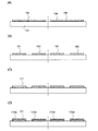
絶縁表面を有する基板上に、単結晶半導体層を設ける方法を図2(A)乃至図2(E)、および図3(A)乃至図3(D)を用いて説明する。 A method for providing a single crystal semiconductor layer over a substrate having an insulating surface will be described with reference to FIGS. 2A to 2E and FIGS. 3A to 3D.
図2(A)に示す半導体基板108は清浄化されており、その表面から電界で加速されたイオンを所定の深さに導入し、脆化層110(分離層)を形成する。イオンの照射は支持基板に形成する単結晶半導体層の厚さを考慮して行われる。当該単結晶半導体層の厚さは1μm以上3μm以下が好ましい。イオンを照射する際の加速電圧はこのような厚さを考慮して、半導体基板108に照射されるようにする。
The
半導体基板108としては、代表的にはp型もしくはn型の単結晶シリコン基板(シリコンウェハ)が用いられる。また、他の単結晶半導体基板としては、シリコン、ゲルマニウムをはじめ、ガリウムヒ素やインジウムリン等の化合物半導体の基板も適用することができる。本実施の形態においては、単結晶半導体基板の所定の深さに水素またはフッ素を導入し、その後熱処理を行って表層の単結晶シリコン層を分離しているが、ポーラスシリコン層上に単結晶シリコンをエピタキシャル成長させた後、ポーラスシリコン層をウォータージェットで分離する方法を適用しても良い。
As the
脆化層110は、水素、ヘリウムもしくはフッ素に代表されるハロゲン元素のイオンを、ドーピング法やイオン注入法によって半導体基板108内に導入することで形成される。ハロゲン元素イオンとしてフッ素イオンを照射する場合にはソースガスとしてBF3を用いれば良い。なお、イオン注入法とはイオン化したガスを質量分離して、所望のイオンを半導体層に導入する方法をいう。
The
半導体基板(例えば単結晶シリコン基板)108にフッ素イオンのようなハロゲン元素イオンを導入した場合、導入されたフッ素が、シリコン結晶格子内のシリコン原子をノックアウトする(追い出す)ことによって空白部分を効果的に作り出し、脆化層110に微小な空洞を作ると考えられている。この場合、比較的低温の熱処理によって脆化層110に形成された微小な空洞の体積変化が生じ、脆化層110に沿って分離することにより薄い単結晶半導体層を形成することができる。フッ素イオンを照射した後に、水素イオンを照射して空洞内に水素を含ませるようにしても良い。半導体基板108から薄い半導体層を分離するために形成する脆化層110は、脆化層110に形成された微小な空洞の体積変化を利用するので、このようにフッ素イオンや水素イオンの作用を有効に利用することが好ましい。
When a halogen element ion such as fluorine ion is introduced into the semiconductor substrate (for example, a single crystal silicon substrate) 108, the introduced fluorine knocks out a silicon atom in the silicon crystal lattice, thereby effectively removing a blank portion. It is considered that a minute cavity is formed in the
また、一または複数の同一原子からなる質量数の異なるイオンを照射しても良い。例えば、水素イオンを照射する場合には、H+、H2 +、H3 +イオンを含ませると共に、H3 +イオンの割合を高めておくことが好ましい。水素イオンを照射する場合に、H+、H2 +、H3 +イオンを含ませると共に、H3 +イオンの割合を高めておくと照射効率を高めることができ、したがって照射時間を短縮することができる。このような構成とすることで、分離を容易に行うことができる。 Moreover, you may irradiate the ion with which the mass number which consists of one or several same atoms differs. For example, when irradiating with hydrogen ions, it is preferable to include H + , H 2 + and H 3 + ions and to increase the ratio of H 3 + ions. When irradiating with hydrogen ions, H + , H 2 + , H 3 + ions are included, and if the ratio of H 3 + ions is increased, the irradiation efficiency can be increased, and therefore the irradiation time can be shortened. Can do. With such a configuration, separation can be easily performed.
脆化層110の形成にあたってはイオンを高ドーズ条件で照射する必要があり、半導体基板108の表面が粗くなってしまう場合がある。そのためイオンが照射される表面に窒化シリコン膜もしくは窒化酸化シリコン膜等によりイオン照射に対する保護膜を50nm乃至200nmの厚さで設けておいても良い。
In forming the
また、脆化層110を形成する前に、半導体基板108を脱脂洗浄し、表面の酸化膜を除去して熱酸化を行っても良い。熱酸化としては通常のドライ酸化でも良いが、酸化雰囲気中にハロゲン元素を添加した酸化を行うことが好ましい。例えば、酸素に対してHClを0.5体積%乃至10体積%(好ましくは3体積%)の割合で含む雰囲気中で、700℃以上の温度で熱処理を行う。好適には950℃乃至1100℃の温度で熱処理を行うと良い。処理時間は0.1時間乃至6時間、好ましくは0.5時間乃至1時間とすれば良い。形成される酸化膜の膜厚としては、10nm乃至1000nm(好適には50nm乃至200nm)、例えば100nmの厚さとすれば良い。
Further, before the
ハロゲン元素を含むものとしてはHClの他にHF、NF3、HBr、Cl2、ClF3、BCl3、F2、Br2等から選ばれた一種または複数種を適用することができる。 As the element containing a halogen element, one or more selected from HF, NF 3 , HBr, Cl 2 , ClF 3 , BCl 3 , F 2 , Br 2 and the like in addition to HCl can be applied.
このような温度範囲で熱処理を行うことで、ハロゲン元素によるゲッタリング効果を得ることができる。ゲッタリングとしては、特に金属不純物を除去する効果がある。すなわち、塩素の作用により金属等の不純物が揮発性の塩化物となって気相中へ離脱して除去される。半導体基板108の表面を化学的機械研磨(CMP)処理をしたものに対しては有効である。また、水素は半導体基板108と形成される酸化膜の界面の欠陥を補償して界面の局在準位密度を低減する作用を奏し、半導体基板108と酸化膜との界面が不活性化されて電気的特性が安定化する。
By performing heat treatment in such a temperature range, a gettering effect by a halogen element can be obtained. Gettering is particularly effective in removing metal impurities. In other words, impurities such as metals become volatile chlorides by the action of chlorine and are released into the gas phase and removed. This is effective for the surface of the
この熱処理により形成される酸化膜中にハロゲン元素を含ませることができる。ハロゲン元素は1×10¹⁷/cm3乃至5×1020/cm3の濃度で含まれることにより金属等の不純物を捕獲して半導体基板108の汚染を防止する保護膜としての機能を発現させることができる。
A halogen element can be contained in the oxide film formed by this heat treatment. The halogen element is contained at a concentration of 1 × 10 17 / cm 3 to 5 × 10 20 / cm 3 so that it can capture an impurity such as a metal and exhibit a function as a protective film that prevents contamination of the
次に、図2(B)で示すように、支持基板101と接合を形成する面に接合層104として酸化シリコン膜を形成する。酸化シリコン膜としては有機シランガスを用いて化学的気相成長法により形成される酸化シリコン膜が好ましい。その他に、シランガスを用いて化学的気相成長法により形成される酸化シリコン膜を適用することもできる。化学的気相成長法による成膜では、半導体基板108に形成した脆化層110から脱ガスが起こらない温度として、例えば、100℃以上400℃以下、好ましくは200℃以上350℃以下の成膜温度が適用される。また、半導体基板108から単結晶半導体層102を分離する熱処理は、成膜温度よりも高い熱処理温度(例えば、400℃以上600℃以下)が適用される。
Next, as illustrated in FIG. 2B, a silicon oxide film is formed as the
接合層104は平滑面を有し親水性表面を形成する。この接合層104としては酸化シリコン膜が適している。特に有機シランガスを用いて化学的気相成長法により形成される酸化シリコン膜が好ましい。有機シランガスとしては、珪酸エチル(TEOS 化学式:Si(OC2H5)4)、トリメチルシラン((CH3)3SiH)、テトラメチルシラン(Si(CH3)4)、テトラメチルシクロテトラシロキサン(TMCTS)、オクタメチルシクロテトラシロキサン(OMCTS)、ヘキサメチルジシラザン(HMDS)、トリエトキシシラン(SiH(OC2H5)3)、トリスジメチルアミノシラン(SiH(N(CH3)2)3)等のシリコン含有化合物を用いることができる。その他に、シランガスを用いて化学的気相成長法により形成される酸化シリコン膜を適用することもできる。
The
上記平滑面を有し親水性表面を形成する接合層104は5nm乃至500nmの厚さで設けられる。この厚さであれば、被成膜表面の表面荒れを平滑化すると共に、当該膜の成長表面の平滑性を確保することが可能である。また、接合する基板との歪みを緩和することができる。支持基板101にも同様の酸化シリコン膜を設けておいても良い。すなわち、支持基板101に単結晶半導体層102を接合するに際し、接合を形成する面の一方もしくは双方に、好ましくは有機シランを原材料として成膜した酸化シリコン膜でなる接合層104を設けることで強固な接合を形成することができる。
The
図2(C)は、支持基板101と、半導体基板108の接合層104が形成された面とを密接させ、両者を接合させる態様を示す。接合を形成する面は、十分に清浄化しておく。そして、支持基板101と接合層104とを密着させることにより接合が形成される。この接合はファン・デル・ワールス力が作用しており、支持基板101と半導体基板108とを圧接することで水素結合により強固な接合を形成することができる。
FIG. 2C shows a mode in which the supporting
良好な接合を形成するために、表面を活性化しておいても良い。例えば、接合を形成する面に原子ビーム又はイオンビームを照射する。原子ビーム又はイオンビームを利用する場合には、アルゴン等の不活性ガス中性原子ビーム又は不活性ガスイオンビームを用いることができる。その他に、プラズマ照射やラジカル処理を行う構成としても良い。このような表面処理により200℃乃至400℃の温度であっても異種材料間の接合を形成することが可能となる。 In order to form a good bond, the surface may be activated. For example, an atomic beam or an ion beam is irradiated to the surface on which the junction is formed. When an atomic beam or an ion beam is used, an inert gas neutral atom beam such as argon or an inert gas ion beam can be used. In addition, a configuration in which plasma irradiation or radical treatment is performed may be employed. By such a surface treatment, it is possible to form a bond between different materials even at a temperature of 200 ° C. to 400 ° C.
単結晶半導体層102を半導体基板108から分離する工程と、支持基板101と単結晶半導体層102とを強固に接合する工程とを別々の加熱処理にて行っても良いし、一回の加熱処理で同時に行っても良い。
The step of separating the single
支持基板101と半導体基板108とを接合層104を介して貼り合わせた後は、加熱処理または加圧処理を行うことが好ましい。加熱処理または加圧処理を行うことで、接合強度を向上させることが可能となる。加圧処理においては、接合面に垂直な方向に圧力が加わるように行い、支持基板101および半導体基板108の耐圧性を考慮して行う。
After the
続いて、図2(D)において、加熱処理を行い、脆化層110の一部を分離面として支持基板101より半導体基板108を分離する。例えば、400℃乃至600℃の熱処理を行うことにより、脆化層110に形成された微小な空洞の体積変化が生じ、脆化層110に沿って分離することが可能となる。加熱処理の温度は、あらかじめ支持基板101に行った加熱処理よりも低い温度で行うと良い。接合層104は支持基板101と接合しているので、支持基板101上には、半導体基板108と同等の結晶性を有する単結晶半導体層102が残存することになる。
Subsequently, in FIG. 2D, heat treatment is performed, and the
さらに、図2(E)に示すとおり、単結晶半導体層102が接合された支持基板101に加熱処理を加える。このときの加熱処理の温度は、あらかじめ支持基板101に行った加熱処理よりも低く、分離時に行った加熱処理よりも高い温度で行うと良い。この加熱処理により、支持基板101はさらにわずかながら熱収縮を生じ、支持基板101上に接合された単結晶半導体層102に圧縮歪を与える。
Further, as shown in FIG. 2E, heat treatment is performed on the supporting
このとき、加熱処理の温度が高すぎる場合、支持基板101の熱収縮が過度に生ずると、前述の接合面もしくは周辺の界面にて、支持基板101から単結晶半導体層102が剥離してしまう場合があるので、この加熱処理の温度は支持基板の材質に応じて適宜調整すると良い。
At this time, in the case where the temperature of the heat treatment is too high, when the thermal contraction of the supporting
次に、図3を用いて、支持基板側に接合層を設けて単結晶半導体層を形成する工程について説明する。図3(A)は酸化シリコン膜121が形成された半導体基板108に電界で加速されたイオンを所定の深さに導入し、脆化層110を形成する工程を示している。イオン照射の詳細は図2(A)の場合と同様である。半導体基板108の表面に酸化シリコン膜121を形成しておくことで、イオン照射によって表面がダメージを受け、平滑性が損なわれるのを防ぐことができる。また、酸化シリコン膜121によって、半導体基板108から形成される単結晶半導体層102に対する不純物の拡散防止効果を発現する。
Next, a process for forming a single crystal semiconductor layer by providing a bonding layer on the supporting substrate side will be described with reference to FIGS. FIG. 3A shows a step of forming the
図3(B)は、ブロッキング層109および接合層104が形成された支持基板101と、半導体基板108の酸化シリコン膜121が形成された面とを密着させて接合を形成する工程を示している。支持基板101上の接合層104と半導体基板108の酸化シリコン膜121を密着させることにより接合が形成される。
FIG. 3B shows a step of forming a bond by closely attaching the
その後、図3(C)で示すように半導体基板108を分離する。単結晶半導体層102を分離する熱処理は、図2(D)の場合と同様にして行う。接合分離工程における加熱処理の温度は、支持基板101にあらかじめ行われた加熱処理温度以下とすると良い。このようにして、図3(C)で示す半導体基板を得ることができる。
Thereafter, the
さらに、図3(D)に示すとおり、単結晶半導体層102が接合された支持基板101に加熱処理を加える。このときの加熱処理の温度は、あらかじめ支持基板101に行った加熱処理よりも低く、分離時に行った加熱処理よりも高い温度で行うと良い。この加熱処理により、支持基板101はさらにわずかながら熱収縮を生じ、支持基板101上に接合された単結晶半導体層102に圧縮歪を与える。
Further, as shown in FIG. 3D, heat treatment is performed on the supporting
このとき、加熱処理の温度が高すぎる場合、支持基板101の熱収縮が過度に生ずると、前述の接合面もしくは周辺の界面にて、支持基板101から単結晶半導体層102が剥離してしまう場合があるので、この加熱処理の温度は支持基板の材質に応じて適宜調整すると良い。
At this time, in the case where the temperature of the heat treatment is too high, when the thermal contraction of the supporting
図2、図3において、支持基板101としては、絶縁表面を有する基板を用いることができ、例えばアルミノホウケイ酸ガラス、アルミノシリケートガラス、バリウムホウケイ酸ガラスの如き無アルカリガラスと呼ばれる電子工業用に使われる各種ガラス基板を適用することができる。また、石英基板を用いても良い。前述の加熱処理温度に応じ、それぞれ適した転移点を有する基板を用いれば良い。以上に説明した工程にしたがって、単結晶半導体層の作製工程を複数回行うことで、一辺が1mを超えるような大型基板上に単結晶半導体層を形成することができる。さらに、基板の加熱処理に伴う熱収縮を応用して、基板上に転置された単結晶半導体層に圧縮歪を与えることができる。
2 and 3, a substrate having an insulating surface can be used as the
また、一旦単結晶半導体層の転置を行い、基板の加熱処理によって該単結晶半導体層に圧縮歪を与えた後、さらに異なる単結晶半導体層を形成することで、同一基板上に通常の単結晶半導体層と、圧縮歪が与えられた単結晶半導体層とを形成することもできる。 In addition, after transposing the single crystal semiconductor layer and applying compressive strain to the single crystal semiconductor layer by heat treatment of the substrate, a different single crystal semiconductor layer is formed, whereby a normal single crystal is formed on the same substrate. A semiconductor layer and a single crystal semiconductor layer to which compressive strain is applied can also be formed.
一方、一旦単結晶半導体層を形成し、基板の加熱処理によって該単結晶半導体層に圧縮歪を与えた後、半導体基板上に設けられた応力緩和されたシリコンゲルマニウム層上に、引っ張り歪を有する単結晶半導体層を成長させた基板を用いて、当該引っ張り歪を有する単結晶半導体層を形成することで、同一基板上に引っ張り歪を有する単結晶半導体層と、圧縮歪が与えられた単結晶半導体層とを形成することができる。 On the other hand, after a single crystal semiconductor layer is formed once, compressive strain is applied to the single crystal semiconductor layer by heat treatment of the substrate, and then tensile strain is applied to the stress-relieved silicon germanium layer provided over the semiconductor substrate. A single crystal semiconductor layer having a tensile strain is formed on the same substrate by forming a single crystal semiconductor layer having the tensile strain using a substrate on which the single crystal semiconductor layer is grown, and a single crystal having a compressive strain. A semiconductor layer can be formed.
上記のような通常の単結晶半導体層や、引っ張り歪を有する単結晶半導体層を形成した後は、圧縮歪を与える際の加熱温度を超えるような加熱処理は避けることが好ましい。なお、このような加熱処理であっても、通常の単結晶半導体層や引っ張り歪みを有する単結晶半導体層には圧縮歪が加わることになるが、その影響は極僅かであり、大きな問題とはならない。 After forming the normal single crystal semiconductor layer as described above or the single crystal semiconductor layer having tensile strain, it is preferable to avoid heat treatment exceeding the heating temperature for applying compressive strain. Even with such a heat treatment, compressive strain is applied to a normal single crystal semiconductor layer or a single crystal semiconductor layer having tensile strain, but the effect is negligible and is a major problem. Don't be.
なお、前述の応力緩和されたシリコンゲルマニウム層上に、格子定数の違いを利用して引っ張り歪を有する単結晶半導体層を成長させる工程に関しては、その工程条件等、本発明においては特に限定しない。 Note that a process for growing a single crystal semiconductor layer having tensile strain using a difference in lattice constant on the stress-relieved silicon germanium layer is not particularly limited in the present invention, such as process conditions.
続いて、支持基板101上に形成された単結晶半導体層を用いてトランジスタを作製し、回路を構成する工程について説明する。
Next, a process for manufacturing a transistor using a single crystal semiconductor layer formed over the supporting
図4(A)に示すとおり、前述の工程にしたがって支持基板101上に接合層104を介して単結晶半導体層150と、圧縮歪を有する単結晶半導体層160とを得た後、フォトマスクを用いて所望の形状のレジストパターンを形成し、フォトリソグラフィ法を用いた加工処理により、図4(B)に示すとおり島状の半導体層151、152、161、162を得る。
As shown in FIG. 4A, after the single
また、半導体層151、152、161、162の端部には、傾斜角(テーパー角)を設けると良い。半導体層151、152、161、162の端部にテーパー角を設ける理由としては、例えば後に形成される絶縁膜の、半導体層の被覆性を向上させる等の効果が期待できるためである。ただし、このテーパー角が小さいと、テーパー領域において、半導体層151、152、161、162の各々の中央部と特性が異なる寄生トランジスタが形成されてしまう場合がある。この寄生トランジスタの影響を避けるためには、その角度は大きい方が好ましい。したがって好適なテーパー角としては、45度乃至90度程度とすることが好ましい。 In addition, an inclination angle (taper angle) is preferably provided at end portions of the semiconductor layers 151, 152, 161, and 162. The reason why the taper angle is provided at the end portions of the semiconductor layers 151, 152, 161, 162 is that, for example, an effect of improving the coverage of the semiconductor layer of an insulating film formed later can be expected. However, if the taper angle is small, a parasitic transistor having different characteristics from the central portion of each of the semiconductor layers 151, 152, 161, and 162 may be formed in the tapered region. In order to avoid the influence of this parasitic transistor, a larger angle is preferable. Therefore, a preferable taper angle is preferably about 45 to 90 degrees.
なお、本明細書において、半導体層の「端部」とは、島状に形成された半導体層の縁部分(エッジ部分)をいう。半導体層の「側面」とは、その縁部分の面をいう。 Note that in this specification, an “end portion” of a semiconductor layer refers to an edge portion (edge portion) of the semiconductor layer formed in an island shape. The “side surface” of the semiconductor layer refers to the surface of the edge portion.
エッチング加工は、プラズマエッチング(ドライエッチング)またはウェットエッチングのいずれを採用しても良いが、大面積基板を処理するにはプラズマエッチングが適している。エッチングガスとしては、CF4、NF3、Cl2、BCl3等のフッ素系または塩素系のガスを用い、HeやAr等の不活性ガスを適宜加えても良い。また、大気圧放電のエッチング加工を適用すれば、局所的な放電加工も可能であり、基板の全面にマスクを形成する必要が無い。 As the etching process, either plasma etching (dry etching) or wet etching may be employed, but plasma etching is suitable for processing a large area substrate. As an etching gas, a fluorine-based or chlorine-based gas such as CF 4 , NF 3 , Cl 2 , or BCl 3 may be used, and an inert gas such as He or Ar may be appropriately added. Further, if an atmospheric pressure discharge etching process is applied, a local electric discharge process is possible, and there is no need to form a mask on the entire surface of the substrate.
本発明において、配線層もしくは電極層を形成する導電層や、所定のパターンを形成するためのマスク等を、液滴吐出法のような選択的にパターンを形成できる方法によって形成しても良い。液滴吐出(噴出)法(方式によっては、インクジェット法とも呼ばれる)は、特定の目的に調合された組成物の液滴を選択的に吐出(噴出)して所定のパターン(導電層や絶縁層等)を形成することができる。この際、被形成領域に濡れ性や密着性を制御する処理を別途行っても良い。また、パターンが転写、または描写できる方法、例えば印刷法(スクリーン印刷やオフセット印刷等、パターンが形成される方法)等も採用することができる。 In the present invention, a conductive layer for forming a wiring layer or an electrode layer, a mask for forming a predetermined pattern, or the like may be formed by a method capable of selectively forming a pattern such as a droplet discharge method. A droplet discharge (ejection) method (also called an ink-jet method depending on the method) is a method of selectively ejecting (jetting) droplets of a composition prepared for a specific purpose to form a predetermined pattern (conductive layer or insulating layer). Etc.) can be formed. At this time, a process for controlling wettability and adhesion may be separately performed on the formation region. In addition, a method by which a pattern can be transferred or drawn, for example, a printing method (a method for forming a pattern such as screen printing or offset printing) or the like can also be employed.
本実施の形態において用いるマスクは、エポキシ樹脂、アクリル樹脂、フェノール樹脂、ノボラック樹脂、メラミン樹脂、ウレタン樹脂等の樹脂材料を用いる。また、ベンゾシクロブテン、パリレン、フッ化アリーレンエーテル、透過性を有するポリイミド等の有機材料、シロキサン系ポリマー等の重合によってできた化合物材料、水溶性ホモポリマーと水溶性共重合体を含む組成物材料等を用いることもできる。あるいは、感光剤を含む市販のレジスト材料を用いても良く、例えばポジ型レジストやネガ型レジストを用いても良い。液滴吐出法を用いる場合、いずれの材料を用いるとしても、その表面張力と粘度は、溶媒の濃度を調整する、界面活性剤を加える等により、適宜調整する。 The mask used in this embodiment mode uses a resin material such as an epoxy resin, an acrylic resin, a phenol resin, a novolac resin, a melamine resin, or a urethane resin. Also, benzocyclobutene, parylene, fluorinated arylene ether, organic materials such as permeable polyimide, compound materials made by polymerization of siloxane polymers, composition materials containing water-soluble homopolymers and water-soluble copolymers Etc. can also be used. Alternatively, a commercially available resist material containing a photosensitizer may be used, and for example, a positive resist or a negative resist may be used. When using the droplet discharge method, regardless of which material is used, the surface tension and viscosity are adjusted as appropriate by adjusting the concentration of the solvent, adding a surfactant, and the like.
続いて、図4(C)に示すとおり、ゲート絶縁膜171を形成し、半導体層151、152、161、162の表面および端部を十分に被覆する。好ましくは、半導体層151、152、161、162の側面と接する領域の膜厚を厚くすることで、半導体層151、152、161、162の端部への電界集中を緩和することができ、リーク電流の発生等を防止することができる。
Subsequently, as shown in FIG. 4C, a
ゲート絶縁膜171はプラズマCVD法またはスパッタ法等を用いて絶縁膜を形成すれば良い。本実施の形態において、ゲート絶縁膜の膜厚は1nm乃至150nm程度、好ましくは10nm乃至80nm程度とすれば良い。
The
ゲート絶縁膜171は酸化シリコン膜、もしくは酸化シリコン膜と窒化シリコン膜の積層構造で形成すれば良い。プラズマCVD法や減圧CVD法により絶縁膜を堆積することで形成しても良いし、プラズマ処理による固相酸化もしくは固相窒化で形成しても良い。また、図4(D)にしめすとおり、半導体層151、152、161、162の表面を自己酸化してゲート絶縁膜172a乃至172dを形成した後、ゲート絶縁膜171を形成することで積層構造としても良い。半導体層表面の自己酸化によって形成される絶縁膜は、緻密で絶縁耐圧が高く、信頼性に優れるといった特徴がある。
The
このような工程でゲート絶縁膜を形成する場合、半導体層151、152、161、162の表面の被覆性はおのずと良好になるため、前述のように半導体層151、152、161、162の端部でのテーパー角形成は行われなくても良い。 When the gate insulating film is formed in such a process, the coverage of the surfaces of the semiconductor layers 151, 152, 161, 162 is naturally good, so that the end portions of the semiconductor layers 151, 152, 161, 162 as described above. It is not necessary to form the taper angle.
プラズマ処理による固相酸化処理もしくは固相窒化処理として、マイクロ波(代表的には2.45GHz)で励起され、電子密度が1×10¹¹/cm3以上1×1013/cm3以下、かつ電子温度が0.5eV以上1.5eV以下のプラズマを利用することが好ましい。固相酸化処理もしくは固相窒化処理において、500℃以下の温度において、緻密な絶縁膜を得るとともに、実用的な反応速度を得るためである。 As solid-phase oxidation treatment or solid-phase nitridation treatment by plasma treatment, the electron density is 1 × 10 11 / cm 3 or more and 1 × 10 13 / cm 3 or less when excited by microwaves (typically 2.45 GHz), and It is preferable to use plasma having an electron temperature of 0.5 eV to 1.5 eV. This is to obtain a dense insulating film and a practical reaction rate at a temperature of 500 ° C. or lower in the solid-phase oxidation treatment or solid-phase nitridation treatment.
このプラズマ処理により半導体層の表面を酸化する場合には、酸素雰囲気下(例えば酸素(O2)または亜酸化窒素(N2O)と希ガス(He、Ne、Ar、Kr、Xeの少なくとも一つを含む)雰囲気下、もしくは酸素または亜酸化窒素と水素(H2)と希ガス雰囲気下)で行う。また、プラズマ処理により半導体層の表面を窒化する場合には、窒素雰囲気下(例えば窒素(N2)と希ガス雰囲気下、窒素と水素と希ガス雰囲気下、もしくはNH3と希ガス雰囲気下)でプラズマ処理を行う。 When the surface of the semiconductor layer is oxidized by this plasma treatment, at least one of oxygen (O 2 ) or nitrous oxide (N 2 O) and a rare gas (He, Ne, Ar, Kr, Xe) is used. Or in an atmosphere of oxygen or nitrous oxide and hydrogen (H 2 ) and a rare gas). In the case of nitriding the surface of the semiconductor layer by plasma treatment, in a nitrogen atmosphere (for example, nitrogen (N 2 ) and a rare gas atmosphere, nitrogen and hydrogen and a rare gas atmosphere, or NH 3 and a rare gas atmosphere) Plasma treatment is performed at
なお、プラズマ処理とは、半導体層、絶縁層、導電層に対する酸化処理、窒化処理、酸窒化処理、水素化処理、表面改質処理を含んでいる。これらの処理は、その目的に応じて供給するガスを選択すれば良い。 Note that the plasma treatment includes oxidation treatment, nitridation treatment, oxynitridation treatment, hydrogenation treatment, and surface modification treatment for a semiconductor layer, an insulating layer, and a conductive layer. These treatments may be performed by selecting a gas to be supplied according to the purpose.
半導体層を酸化処理もしくは窒化処理を行うには以下のようにすれば良い。まず、処理室内を真空にし、ガス供給部から酸素または窒素を含むプラズマ処理用ガスを導入する。基板温度は室温か、又は温度制御部により100℃乃至500℃に加熱する。 The semiconductor layer may be oxidized or nitrided as follows. First, the processing chamber is evacuated and a plasma processing gas containing oxygen or nitrogen is introduced from a gas supply unit. The substrate temperature is room temperature or heated to 100 ° C. to 500 ° C. by a temperature controller.
次に、マイクロ波供給部からアンテナにマイクロ波を供給する。そしてマイクロ波をアンテナから誘電体板を通して処理室内に導入することによって、プラズマを生成する。マイクロ波の導入によりプラズマ励起を行うと、低電子温度(3eV以下、好ましくは1.5eV以下)で高電子密度(1×10¹¹/cm3以上)のプラズマを生成することができる。この高密度プラズマで生成された酸素ラジカル(OHラジカルを含む場合もある)および/または窒素ラジカル(NHラジカルを含む場合もある)によって、半導体層の表面を酸化または窒化することができる。プラズマ処理用ガスにアルゴン等の希ガスを混合させると、希ガスの励起種により酸素ラジカルや窒素ラジカルを効率よく生成することができる。この方法は、プラズマで励起した活性なラジカルを有効に使うことにより、500℃以下の低温で固相反応による酸化、窒化、もしくは酸化と窒化の同時処理を行うことができる。 Next, a microwave is supplied from the microwave supply unit to the antenna. Then, plasma is generated by introducing the microwave from the antenna through the dielectric plate into the processing chamber. When plasma excitation is performed by introduction of microwaves, plasma with a low electron temperature (3 eV or less, preferably 1.5 eV or less) and a high electron density (1 × 10 11 / cm 3 or more) can be generated. The surface of the semiconductor layer can be oxidized or nitrided by oxygen radicals (which may include OH radicals) and / or nitrogen radicals (which may include NH radicals) generated by this high-density plasma. When a rare gas such as argon is mixed with the plasma processing gas, oxygen radicals and nitrogen radicals can be efficiently generated by the excited species of the rare gas. In this method, active radicals excited by plasma can be effectively used to perform oxidation, nitridation, or simultaneous oxidation and nitridation by solid-phase reaction at a low temperature of 500 ° C. or lower.
上記のようなプラズマ処理による固相酸化処理もしくは固相窒化処理を行うことで、耐熱温度が700℃以下のガラス基板を用いても、950℃乃至1050℃で形成される熱酸化膜と同等な絶縁層を得ることができる。すなわち、トランジスタのゲート絶縁膜として信頼性の高い膜を得ることができる。 By performing solid-phase oxidation treatment or solid-phase nitridation treatment by plasma treatment as described above, even if a glass substrate having a heat resistant temperature of 700 ° C. or lower is used, it is equivalent to a thermal oxide film formed at 950 ° C. to 1050 ° C. An insulating layer can be obtained. That is, a highly reliable film can be obtained as a gate insulating film of a transistor.
また、ゲート絶縁膜の形成には、高誘電率材料を用いても良い。ゲート絶縁膜に高誘電率材料を用いることにより、ゲートリーク電流を低減することができる。代表的な高誘電率材料としては、二酸化ジルコニウム、酸化ハフニウム、二酸化チタン、五酸化タンタル等を用いることができる。また、プラズマ処理による固相酸化により、酸化シリコン膜を形成しても良い。 Further, a high dielectric constant material may be used for forming the gate insulating film. By using a high dielectric constant material for the gate insulating film, gate leakage current can be reduced. As typical high dielectric constant materials, zirconium dioxide, hafnium oxide, titanium dioxide, tantalum pentoxide, or the like can be used. Further, a silicon oxide film may be formed by solid phase oxidation by plasma treatment.
また、GRTA法、LRTA法等を用いて半導体領域表面を酸化し、熱酸化膜を形成することで、薄い酸化シリコン膜を形成することもできる。なお、低い成膜温度でゲートリーク電流の少ない緻密な絶縁膜を形成するには、アルゴン等の希ガス元素を反応ガスに含ませ、形成される絶縁膜中に混入させると良い。 In addition, a thin silicon oxide film can be formed by oxidizing the surface of the semiconductor region using a GRTA method, an LRTA method, or the like to form a thermal oxide film. Note that in order to form a dense insulating film with little gate leakage current at a low deposition temperature, a rare gas element such as argon is preferably contained in a reaction gas and mixed into the formed insulating film.
続いて、ゲート絶縁膜171上に、ゲート電極層として用いる膜厚20nm乃至100nmの第1の導電膜と、膜厚100nm乃至400nmの第2の導電膜とを積層形成する。第1の導電膜および第2の導電膜は、スパッタリング法、蒸着法、CVD法等の手法により形成することができる。第1の導電膜および第2の導電膜はタンタル(Ta)、タングステン(W)、チタン(Ti)、モリブデン(Mo)、アルミニウム(Al)、銅(Cu)、クロム(Cr)、ネオジム(Nd)等から選ばれた元素、または前記元素を主成分とする合金材料もしくは化合物材料で形成すれば良い。また、第1の導電膜および第2の導電膜として、リン等の不純物元素をドーピングした多結晶シリコン膜に代表される半導体膜や、AgPdCu合金等を用いても良い。また、ゲート電極層として用いる導電膜は、ここで説明した積層構造には限定されず、単層で形成しても良いし、例えば第1の導電膜として膜厚50nmのタングステン膜、第2の導電膜として膜厚500nmのアルミニウムとシリコンの合金(Al−Si)膜、第3の導電膜として膜厚30nmの窒化チタン膜を順次積層した3層構造としても良い。また、3層構造とする場合、第1の導電膜のタングステンに代えて窒化タングステンを用いても良いし、第2の導電膜のアルミニウムとシリコンの合金(Al−Si)膜に代えてアルミニウムとチタンの合金(Al−Ti)膜を用いても良いし、第3の導電膜の窒化チタン膜に代えてチタン膜を用いても良い。本実施の形態においては、第1の導電膜として窒化タンタルを膜厚30nmにて形成し、第2の導電膜としてタングステン(W)を膜厚370nmにて形成する。
Next, a first conductive film with a thickness of 20 nm to 100 nm and a second conductive film with a thickness of 100 nm to 400 nm used as a gate electrode layer are stacked over the
次に、フォトリソグラフィ法を用いて第1の導電膜および第2の導電膜を所望の形状に加工して、第1のゲート電極層173a乃至176aおよび、第2のゲート電極層173b乃至176bの積層構造でなるゲート電極173乃至176を形成する(図5(A)参照)。ICP(Inductively Coupled Plasma:誘導結合型プラズマ)エッチング法を用い、エッチング条件(コイル型の電極層に印加される電力量、基板側の電極温度等)を適宜調節することにより、第1のゲート電極層および第2のゲート電極層を所望のテーパー形状を有するようにエッチングすることができる。また、テーパー形状は、マスクの形状によっても角度等を制御することができる。なお、エッチング用ガスとしては、Cl2、BCl3、SiCl4もしくはCCl4などを代表とする塩素系ガス、CF4、SF6もしくはNF3等を代表とするフッ素系ガスまたはO2を適宜用いることができる。
Next, the first conductive film and the second conductive film are processed into desired shapes by using a photolithography method, and the first
本実施の形態においては第1のゲート電極層、第2のゲート電極層を垂直な側面を有して形成する例を示しているが、本発明はそれに限定されず、第1のゲート電極層および第2のゲート電極層両方がテーパー形状を有していても良いし、いずれか一方のみがテーパー形状を有し、他方は異方性エッチングによって垂直な側面を有していても良い。またテーパー角も積層するゲート電極層間で異なっていても良いし、同一でも良い。テーパー形状を有することによって、その上に積層する膜の被覆性が向上し、欠陥が低減されるために信頼性が向上する。 In this embodiment mode, an example in which the first gate electrode layer and the second gate electrode layer are formed to have vertical side surfaces is shown; however, the present invention is not limited to this, and the first gate electrode layer is formed. Both the second gate electrode layer and the second gate electrode layer may have a tapered shape, or only one of them may have a tapered shape, and the other may have a vertical side surface by anisotropic etching. The taper angle may be different between the stacked gate electrode layers, or may be the same. By having a tapered shape, the coverage of a film stacked thereon is improved, and defects are reduced, so that reliability is improved.
また、図5(A)では示していないが、ゲート電極層を形成する際のエッチング工程において、ゲート絶縁膜171は多少エッチングされ、膜厚が減る(所謂、膜減り)ことがある。
Although not shown in FIG. 5A, in the etching step for forming the gate electrode layer, the
続いて、ゲート電極173乃至176をマスクとしてn型を付与する不純物元素177を添加し、第1の不純物領域177a乃至177hを形成する(図5(B)参照)。本実施の形態においては、不純物元素を含むドーピングガスとしてホスフィン(PH3)(ドーピングガスはPH3を水素(H2)で希釈しており、ガス中のPH3の比率は5%)を用い、ガス流量80sccm、ビーム電流54μA/cm、加速電圧50kV、添加するドーズ量7.0×1013/cm2でドーピングを行う。ここでは、第1の不純物領域177a乃至177hに、n型を付与する不純物元素が1×1017/cm3乃至5×1018/cm3程度の濃度で含まれるように添加する。本実施の形態では、n型を付与する不純物元素としてリン(P)を用いる。
Subsequently, an
次に、半導体層152、161の一部、162を覆うマスク178a乃至178cを形成する。マスク178a乃至178cおよびゲート電極173をマスクとして、n型を付与する不純物元素179を添加し、第2の不純物領域179a乃至179d、第3の不純物領域177i、177jを形成する。本実施の形態においては、不純物元素を含むドーピングガスとしてPH3(ドーピングガスはPH3を水素(H2)で希釈しており、ガス中のPH3の比率は5%)を用い、ガス流量80sccm、ビーム電流540μA/cm、加速電圧70kV、添加するドーズ量5.0×1015/cm2にてドーピングを行う。ここでは、第2の不純物領域179a乃至179dにn型を付与する不純物元素が5×1019/cm3乃至5×1020/cm3程度の濃度で含まれるように添加する。また、半導体層151にチャネル形成領域180a、半導体層161にチャネル形成領域180bが形成される(図5(C)参照)。
Next, masks 178 a to 178 c that cover part of the semiconductor layers 152 and 161 and 162 are formed. Using the
第2の不純物領域179a乃至179dは高濃度n型不純物領域であり、n型トランジスタのソース領域、ドレイン領域として機能する。一方、第3の不純物領域177i、177jは低濃度n型不純物領域であり、所謂LDD(Lightly Doped Drain)領域となる。また第3の不純物領域177i、177jはゲート電極層に覆われていない、オフセット領域と呼ばれる領域に形成されているため、トランジスタのオフリーク電流を低減する効果がある。この結果、高電圧印加下での信頼性の高いトランジスタが実現する。
The
続いて、先ほどのマスク178a乃至178cを除去した後、半導体層151、161を覆うマスク181a、181bを形成する。マスク181a、181bおよびゲート電極174、176をマスクとして、p型を付与する不純物元素182を添加し、p型不純物領域182a乃至182dが形成される。本実施の形態においては、p型を付与する不純物元素としてボロン(B)を用いるため、不純物元素を含むドーピングガスとしてジボラン(B2H6)(ドーピングガスはB2H6を水素(H2)で希釈しており、ガス中のB2H6の比率は15%)を用い、ガス流量70sccm、ビーム電流180μA/cm、加速電圧80kV、添加するドーズ量2.0×1015/cm2にてドーピングを行う。ここでは、p型不純物領域182a乃至182dにp型を付与する不純物元素が1×1020/cm3乃至5×1021/cm3程度の濃度で含まれるように添加する。また、半導体層152、162にはチャネル形成領域183a、183bが形成される(図5(D)参照)。
Subsequently, after removing the
p型不純物領域182a乃至182dは高濃度p型不純物領域であり、p型トランジスタのソース領域、ドレイン領域として機能する。
The p-
次に、半導体層151、152、161、162に添加した不純物元素を活性化するために加熱処理、強光の照射、またはレーザ光の照射を行っても良い。活性化と同時にゲート絶縁膜へのプラズマダメージやゲート絶縁層と半導体層との界面へのプラズマダメージを回復することができる。 Next, heat treatment, intense light irradiation, or laser light irradiation may be performed to activate the impurity element added to the semiconductor layers 151, 152, 161, and 162. Simultaneously with activation, plasma damage to the gate insulating film and plasma damage to the interface between the gate insulating layer and the semiconductor layer can be recovered.
次いで、図6(A)に示すように、半導体層およびゲート電極を覆う層間絶縁膜を形成する。本実施の形態においては、層間絶縁膜184の単層構造として示した。層間絶縁膜184の材料としては、スパッタ法またはプラズマCVD法を用いて形成された窒化シリコン膜、酸化窒化シリコン膜、窒化酸化シリコン膜、酸化シリコン膜でも良く、2層または3層以上の積層構造としても良い。
Next, as illustrated in FIG. 6A, an interlayer insulating film that covers the semiconductor layer and the gate electrode is formed. In this embodiment mode, a single layer structure of the
さらに、窒素雰囲気下で300℃乃至550℃で1時間乃至12時間の熱処理を行い、半導体層を水素化する。好ましくは、400℃乃至500℃で行う。この工程は層間絶縁膜184に含まれる水素により半導体層のダングリングボンドを終端する工程である。本実施の形態においては、410℃にて1時間加熱処理を行う。
Further, heat treatment is performed at 300 ° C. to 550 ° C. for 1 hour to 12 hours in a nitrogen atmosphere to hydrogenate the semiconductor layer. Preferably, it is performed at 400 ° C. to 500 ° C. This step is a step in which dangling bonds in the semiconductor layer are terminated by hydrogen contained in the
層間絶縁膜184としては他に窒化アルミニウム、酸化窒化アルミニウム、窒素含有量が酸素含有量よりも多い窒化酸化アルミニウムまたは酸化アルミニウム、ダイヤモンドライクカーボン(DLC)、窒素含有炭素膜(CN)その他の無機絶縁性材料を含む物質から選ばれた材料で形成することができる。また、シロキサン樹脂を用いても良い。シロキサン樹脂とは、Si−O−Si結合を含む樹脂をいう。シロキサンは、シリコンと酸素との結合で骨格構造が構成される。置換基として、少なくとも水素を含む有機基(例えばアルキル基、芳香族炭化水素)が用いられる。置換基としてフルオロ基を用いても良い。または、少なくとも水素を含む有機基とフルオロ基とを用いても良い。また、有機絶縁性材料を用いても良く、有機材料としては、ポリイミド、アクリル、ポリアミド、ポリイミドアミド、レジストまたはベンゾシクロブテン、ポリシラザン等を用いることができる。平坦性の良い塗布法によって形成される塗布膜を用いても良い。
The
層間絶縁膜184の形成には、前述のスパッタ法、プラズマCVD法の他、ディップ、スプレーや各種コーターによる塗布、蒸着法等を採用することができる。また、液滴吐出法によって形成しても良い。この場合、材料液を節約することができる。また、液滴吐出法の他にパターンが転写、または描写できる方法、例えば印刷法(スクリーン印刷やオフセット印刷等、パターンが形成される方法)等も採用することができる。
For the formation of the
次いで、レジストからなるマスクを用いて、層間絶縁膜およびゲート絶縁膜に、半導体層およびゲート電極層に達するコンタクトホール(開口部)を形成する。エッチングは、用いる材料の選択比によって、一回で行っても複数回行っても良い。またウェットエッチングでもドライエッチングでも良く、両方用いても良い。ウェットエッチングのエッチャントは、フッ化水素アンモニウムおよびフッ化アンモニウムを含む混合溶液のようなフッ酸系の溶液を用いると良い。エッチングガスとしては、Cl2、BCl3、SiCl4もしくはCCl4等を代表とする塩素系ガス、CF4、SF6もしくはNF3等を代表とするフッ素系ガスまたはO2を適宜用いることができる。また用いるエッチングガスに不活性ガスを添加しても良い。添加する不活性元素としては、He、Ne、Ar、Kr、Xeから選ばれた一種または複数種の元素を用いることができる。 Next, contact holes (openings) reaching the semiconductor layer and the gate electrode layer are formed in the interlayer insulating film and the gate insulating film using a resist mask. Etching may be performed once or a plurality of times depending on the selection ratio of the material to be used. Further, wet etching or dry etching may be used, or both may be used. As an etchant for wet etching, a hydrofluoric acid-based solution such as a mixed solution containing ammonium hydrogen fluoride and ammonium fluoride is preferably used. The etching gas may be Cl 2, BCl 3, SiCl 4 or a chlorine-based gas typified by CCl 4 and the like, a fluorine-based gas or O 2 typified by CF 4, SF 6 or NF 3, or the like as appropriate . Further, an inert gas may be added to the etching gas used. As the inert element to be added, one or more elements selected from He, Ne, Ar, Kr, and Xe can be used.
開口部を覆うように導電膜を形成し、該導電膜を所望の形状にエッチングして、各ソース領域またはドレイン領域の一部、あるいはゲート電極とそれぞれ電気的に接続する配線185a乃至185iを形成する。配線185a乃至185iは、液滴吐出法、印刷法、電解メッキ法等により、所定の場所に選択的に導電層を形成することで形成しても良い。更にはリフロー法、ダマシン法を用いても良い。配線185a乃至185iの材料は、Ag、Au、Cu、Ni、Pt、Pd、Ir、Rh、W、Al、Ta、Mo、Cd、Zn、Fe、Ti、Zr、Ba等の金属、およびSi、Ge、またはその化合物、もしくはその窒化物を用いて形成する。また、これらの積層構造としても良い。本実施の形態においては、チタン(Ti)を膜厚60nmにて形成し、窒化チタンを膜厚40nmにて形成し、アルミニウムを膜厚700nmにて形成し、チタンを膜厚200nmにて形成して積層構造とし、所望の形状に加工する(図6(B)参照)。
A conductive film is formed so as to cover the opening, and the conductive film is etched into a desired shape to form wirings 185a to 185i that are electrically connected to a part of each source region or drain region or the gate electrode. To do. The
以上の工程で、半導体層151、152を活性層として用いたトランジスタ190、191と、圧縮歪を有する単結晶半導体層161、162を活性層として用いたトランジスタ192、193とを同一基板上に有する半導体装置が完成する(図6(C)参照)。
Through the above steps, the
図1(A)、図1(B)に、本実施の形態にしたがって作製された半導体装置の一例を示す。図1(A)は本発明の半導体装置における、平面図であり、図1(B)は、図1(A)における線X−Y間の断面図である。 1A and 1B illustrate an example of a semiconductor device manufactured in accordance with this embodiment mode. 1A is a plan view of the semiconductor device of the present invention, and FIG. 1B is a cross-sectional view taken along line XY in FIG.
図1(A)、図1(B)に示すように、同一の支持基板101上に、第1の回路群1201および第2の回路群1202が形成されている。単結晶半導体層を用いて形成されたトランジスタ190、191を用いて、第1の回路群1201が構成され、圧縮歪を有する単結晶半導体層を用いて形成されたトランジスタ192、193を用いて、第2の回路群1202が構成されている。
As shown in FIGS. 1A and 1B, a
(実施の形態2)
本実施の形態においては、本発明を適用して作製された表示機能を有する半導体装置の例を、図7を参照して説明する。
(Embodiment 2)
In this embodiment, an example of a semiconductor device having a display function manufactured by applying the present invention will be described with reference to FIGS.
図7(A)は、アクティブマトリクス型の表示装置を示したものである。支持基板1001上に、複数の画素回路をマトリクス状に配置した画素部1002、データドライバ1003、スキャンドライバ1004が形成されている。さらに、対向基板1005(封止基板)によって上面が封止、密封されている。フレキシブルプリント基板(FPC)1006を介して、表示装置の駆動に必要な制御信号、映像信号、および駆動電源の供給を外部より行う。また、図7(A)中、線A−B間の断面を図7(B)に示す。
FIG. 7A illustrates an active matrix display device. A
図7(B)は、画素部をエレクトロルミネッセンス(EL)素子を用いて構成した場合のアクティブマトリクス型表示装置の断面を示している。 FIG. 7B illustrates a cross section of an active matrix display device in which a pixel portion is formed using an electroluminescence (EL) element.
データドライバ1003、スキャンドライバ1004は、外部より供給される映像信号を、それぞれの画素に入力するための処理を、外部より供給される制御信号にしたがって行っており、表示装置の中では比較的高速動作が求められる。
The
本発明によると、データドライバ1003、スキャンドライバ1004は、前述の工程によって支持基板1001上に形成された単結晶半導体層を活性層として形成されたトランジスタ350、351を用いて構成されており、該トランジスタ350、351は、データドライバ1003、スキャンドライバ1004の駆動に十分な能力を有している。
According to the present invention, the
なお、本発明を適用して表示装置を作製する場合には、支持基板1001はガラス、プラスチック等でなる透光性を有する基板を用いるのが好ましい。無論、前述の工程を通じての加熱処理に耐えうる材質を選択すべきなのは言うまでも無い。
Note that in the case of manufacturing a display device by applying the present invention, the
一方、画素部1002においては、映像の表示を行う際には、各画素に設けられたEL素子に電流を供給し、該EL素子が発光することによって行う。したがって、EL素子への電流供給を制御するトランジスタにも、十分な駆動能力が求められる。
On the other hand, in the
本発明によると、画素部1002は、前述の工程によって支持基板1001上に形成された、圧縮歪を有する単結晶半導体層を活性層として形成されたトランジスタ352を用いて形成されている。図7(B)において、トランジスタ352はpチャネル型を用いている。これは、EL素子への電流の供給は、表示期間を通じて継続して行われる、すなわち、継続してトランジスタに電流が流れるため、nチャネル型トランジスタを用いると、ホットキャリア劣化等が心配されるためである。よって、画素部を構成しているpチャネル型トランジスタ352は、その活性層に圧縮歪が与えられており、正孔の移動度が向上している。そのため、pチャネル型トランジスタ352は、チャネル幅を小さく形成しても、十分にEL素子に電流の供給が行える。
According to the present invention, the
付随的な効果としては、前述のpチャネル型トランジスタの正孔移動度の向上にともなって、画素部に占めるトランジスタ352の配置面積は相対的に小さくすることができ、開口率(画素部全体の面積における、発光に寄与する領域の占める割合)を向上させることができる。
As an incidental effect, as the hole mobility of the above-described p-channel transistor is improved, the arrangement area of the
半導体層に引っ張り歪を与えた場合と、圧縮歪を与えた場合とでは、移動度の向上に繋がるトランジスタの極性が異なる。具体的には、半導体層に引っ張り歪を与えた場合、nチャネル型トランジスタにおいて電子移動度が向上し、半導体層に圧縮歪を与えた場合、pチャネル型トランジスタにおいて正孔移動度が向上すると言われている。本発明の半導体装置においては、構成する回路群の各々の特性に応じて、該回路を構成するためのトランジスタをいずれの半導体層を用いて形成するかを適宜選択すれば良い。 The polarity of the transistor that leads to an improvement in mobility differs between when tensile strain is applied to the semiconductor layer and when compressive strain is applied. Specifically, when tensile strain is applied to a semiconductor layer, electron mobility is improved in an n-channel transistor, and when compressive strain is applied to a semiconductor layer, hole mobility is improved in a p-channel transistor. It has been broken. In the semiconductor device of the present invention, which semiconductor layer is used to form a transistor for forming the circuit may be appropriately selected according to the characteristics of each circuit group to be formed.
なお、本実施の形態においては、画素部の周辺に設ける回路としてスキャンドライバ、データドライバを例示して説明したが、他のロジック回路を同時に作り込んでも良い。 In this embodiment mode, the scan driver and the data driver are exemplified as the circuits provided in the periphery of the pixel portion. However, other logic circuits may be formed at the same time.
続いて、画素部の詳細な構成について、図7(B)を用いて説明する。 Next, a detailed structure of the pixel portion will be described with reference to FIG.
トランジスタ352の電極に接して、画素電極層である第1の電極層320が形成されている。第1の電極層320は、支持基板1001側から光を放射する場合には、インジウム錫酸化物(ITO)、酸化シリコンを含むインジウム錫酸化物(ITSO)、酸化亜鉛(ZnO)を含むインジウム亜鉛酸化物(IZO)、酸化亜鉛、酸化亜鉛にガリウム(Ga)をドープしたもの、酸化錫(SnO2)、酸化タングステンを含むインジウム酸化物、酸化タングステンを含むインジウム亜鉛酸化物、酸化チタンを含むインジウム酸化物、酸化チタンを含むインジウム錫酸化物等、透光性を有する導電性材料を用いて形成することができる。
A
また、透光性を有さない金属膜のような材料であっても、膜厚をごく薄く(好ましくは5nm乃至30nm程度の厚さ)して光を透過可能な状態に形成することで、第1の電極層320から光を放射することが可能となる。また、第1の電極層320に用いることのできる金属薄膜としては、チタン、タングステン、ニッケル、金、白金、銀、アルミニウム、マグネシウム、カルシウム、リチウム、亜鉛、およびそれらの合金からなる導電膜、または窒化チタン、窒化タングステン等の前記元素を主成分とする化合物材料からなる膜を用いることができる。
In addition, even a material such as a metal film that does not have translucency can be formed so that light can be transmitted through a very thin film thickness (preferably about 5 nm to 30 nm). Light can be emitted from the
第1の電極層320は、トランジスタ352のソース電極もしくはドレイン電極と電気的に接続できれば良く、その接続構造は本実施の形態には限定されない。ソース電極もしくはドレイン電極上に層間絶縁膜となる絶縁層を形成し、配線層によって第1の電極層320と電気的に接続する構造を用いても良い。また、光を支持基板1001とは反対側に放射させる構造とする場合(上面放射型の表示装置を作製する場合)には、第1の電極層320には透光性は要求されないので、金、銀、銅、タングステン、アルミニウム等の金属材料を用いることができる。
The
また、絶縁層321(隔壁とも呼ばれる)が選択的に形成されている。絶縁層321は、第1の電極層320上に開口部を有するように形成する。本実施の形態においては、絶縁層321を全面に形成した後、レジスト等のマスクによってエッチングし加工する。絶縁層321を、直接選択的に形成できる液滴吐出法や印刷法等を用いて形成する場合には、エッチングによる加工は必ずしも必要でない。
An insulating layer 321 (also referred to as a partition wall) is selectively formed. The insulating
絶縁層321は、酸化シリコン、窒化シリコン、酸化窒化シリコン、酸化アルミニウム、窒化アルミニウム、酸化窒化アルミニウムその他の無機絶縁性材料、またはアクリル酸、メタクリル酸およびこれらの誘導体、またはポリイミド、芳香族ポリアミド、ポリベンゾイミタゾール等の耐熱性高分子、又はシロキサン樹脂材料を用いることができる。絶縁層321は曲率半径が連続的に変化する形状が好ましく、上に形成される発光層322、第2の電極層323の被覆性が向上する。
The insulating
発光層322として、例えば赤色(R)、緑色(G)、青色(B)の発光を示す材料をそれぞれ蒸着マスクを用いた蒸着法等によって選択的に形成する。赤色(R)、緑色(G)、青色(B)の発光を示す材料は、液滴吐出法によって形成することもできる。また、各色の材料が均一に蒸着された基板を用意し、支持基板1001上に対向させて配置しておき、裏面よりレーザ照射等によって所望の位置に発光材料を転写するレーザ転写法を用いても良い。液滴吐出法やレーザ転写法を用いると、蒸着マスクを用いずとも所望の位置に選択的に発光材料を形成することができる。
As the
発光層322上に第2の電極層323を積層形成し、最後に対向基板1005(封止基板)によって画素部の封止を行って、表示装置を完成する。
A
特に図示しないが、第2の電極層323を覆うようにしてパッシベーション膜を設けることは、発光素子の信頼性向上に有効である。
Although not particularly illustrated, providing a passivation film so as to cover the
表示装置を構成する際に設けるパッシベーション膜は、単層構造でも多層構造でもよい。パッシベーション膜としては、窒化珪素、酸化珪素、酸化窒化珪素、窒化酸化珪素、窒化アルミニウム(AlN)、酸化窒化アルミニウム、窒素含有量が酸素含有量よりも多い窒化酸化アルミニウムまたは酸化アルミニウム、ダイアモンドライクカーボン、窒素含有炭素膜を含む絶縁膜からなり、該絶縁膜を単層もしくは組み合わせた積層を用いることができる。例えば窒素含有炭素膜、窒化珪素のような積層、また有機材料を用いることもでき、スチレンポリマーなど高分子の積層としても良い。また、シロキサン材料(無機シロキサン、有機シロキサン)を用いてもよい。 The passivation film provided when forming the display device may have a single layer structure or a multilayer structure. Examples of the passivation film include silicon nitride, silicon oxide, silicon oxynitride, silicon nitride oxide, aluminum nitride (AlN), aluminum oxynitride, aluminum nitride oxide or aluminum oxide having a nitrogen content higher than the oxygen content, diamond-like carbon, The insulating film includes a nitrogen-containing carbon film, and a single layer or a combination of the insulating films can be used. For example, a nitrogen-containing carbon film, a laminate such as silicon nitride, or an organic material can be used, or a polymer laminate such as a styrene polymer may be used. A siloxane material (inorganic siloxane or organic siloxane) may also be used.
この際、カバレッジの良い膜をパッシベーション膜として用いることが好ましく、炭素膜、特にDLC膜を用いることは有効である。DLC膜は室温から100℃以下の温度範囲で成膜可能であるため、耐熱性の低い電界発光層の上方にも容易に成膜することができる。DLC膜は酸素に対するブロッキング効果が高く、電界発光層の酸化を抑制することが可能である。そのため、この後に続く封止工程を行う間に電界発光層が酸化する問題を解決できる。 At this time, it is preferable to use a film with good coverage as the passivation film, and it is effective to use a carbon film, particularly a DLC film. Since the DLC film can be formed in a temperature range from room temperature to 100 ° C., it can be easily formed over the electroluminescent layer having low heat resistance. The DLC film has a high blocking effect against oxygen and can suppress oxidation of the electroluminescent layer. Therefore, the problem that the electroluminescent layer is oxidized during the subsequent sealing process can be solved.
支持基板1001(絶縁基板)と対向基板1005(封止基板)の間には充填剤を封入してシール材により封止することができる。充填剤の封入には、滴下法を用いることもできる。充填剤の代わりに、窒素などの不活性ガスを充填してもよい。また、乾燥剤を表示装置内に設置することによって、発光素子の水分による劣化を防止することができる。 A filler can be sealed between the supporting substrate 1001 (insulating substrate) and the counter substrate 1005 (sealing substrate) and sealed with a sealing material. A dripping method can also be used to enclose the filler. Instead of the filler, an inert gas such as nitrogen may be filled. Further, by installing the desiccant in the display device, the light emitting element can be prevented from being deteriorated by moisture.
なお、本実施の形態では、ガラス基板で発光素子及び液晶素子を封止した場合を示すが、封止の処理とは、発光素子を水分から保護するための処理であり、カバー材で機械的に封入する方法、熱硬化性樹脂又は紫外光硬化性樹脂で封入する方法、金属酸化物や窒化物等のバリア能力が高い薄膜により封止する方法のいずれかを用いる。カバー材としては、ガラス、セラミックス、プラスチックもしくは金属を用いることができるが、カバー材側に光を放射させる場合は透光性でなければならない。また、カバー材と上記発光素子が形成された基板とは熱硬化性樹脂又は紫外光硬化性樹脂等のシール材を用いて貼り合わせられ、熱処理又は紫外光照射処理によって樹脂を硬化させて密閉空間を形成する。この密閉空間の中に酸化バリウムに代表される吸湿材を設けることも有効である。この吸湿材は、シール材の上に接して設けても良いし、発光素子よりの光を妨げないような、隔壁の上や周辺部に設けても良い。さらに、カバー材と発光素子の形成された基板との空間を熱硬化性樹脂若しくは紫外光硬化性樹脂で充填することも可能である。この場合、熱硬化性樹脂若しくは紫外光硬化性樹脂の中に酸化バリウムに代表される吸湿材を添加しておくことは有効である。 Note that in this embodiment mode, a case where a light-emitting element and a liquid crystal element are sealed with a glass substrate is shown; however, the sealing process is a process for protecting the light-emitting element from moisture and is mechanically covered with a cover material. Any of a method of encapsulating in a thin film, a method of encapsulating with a thermosetting resin or an ultraviolet light curable resin, or a method of encapsulating with a thin film having a high barrier ability such as a metal oxide or a nitride is used. As the cover material, glass, ceramics, plastic, or metal can be used. However, when light is emitted to the cover material side, it must be translucent. In addition, the cover material and the substrate on which the light emitting element is formed are bonded together using a sealing material such as a thermosetting resin or an ultraviolet light curable resin, and the resin is cured by heat treatment or ultraviolet light irradiation treatment to form a sealed space. Form. It is also effective to provide a hygroscopic material typified by barium oxide in this sealed space. This hygroscopic material may be provided in contact with the sealing material, or may be provided on the partition wall or in the peripheral portion so as not to block light from the light emitting element. Further, the space between the cover material and the substrate on which the light emitting element is formed can be filled with a thermosetting resin or an ultraviolet light curable resin. In this case, it is effective to add a moisture absorbing material typified by barium oxide in the thermosetting resin or the ultraviolet light curable resin.
なお、本実施の形態においては、表示装置の一例としてEL素子を画素部に用いた例を示したが、本発明は表示装置の形式に限定を加えるものでは無い。画素部に液晶素子を用いた表示装置においても、本実施の形態のとおり、周辺回路部と画素部に、適宜単結晶半導体層を用いて作成されたトランジスタ、圧縮歪を与えられた単結晶半導体層を用いて作成されたトランジスタをそれぞれ適用しても良い。 Note that although an example in which an EL element is used for a pixel portion is described as an example of a display device in this embodiment, the present invention does not limit the type of the display device. Even in a display device using a liquid crystal element in a pixel portion, as in this embodiment mode, a transistor formed using a single crystal semiconductor layer as appropriate in a peripheral circuit portion and a pixel portion, a single crystal semiconductor subjected to compressive strain Each transistor formed using layers may be applied.
また、周辺回路に用いる単結晶半導体層を用いて作成されたトランジスタに代わり、引っ張り歪を与えられた単結晶半導体層を用いて作成されたトランジスタを用いても良い。 Further, instead of a transistor formed using a single crystal semiconductor layer used for a peripheral circuit, a transistor formed using a single crystal semiconductor layer subjected to tensile strain may be used.
本実施の形態は、実施の形態1と適宜組み合わせて用いることができる。 This embodiment can be combined with Embodiment 1 as appropriate.
(実施の形態3)
本発明の半導体装置においては、支持基板101上に薄い単結晶半導体層150と、厚い単結晶半導体層160とを貼り合わせによって形成することを特徴としているが、各単結晶半導体層の最表面には、イオン照射工程による分離面の一部が残留している場合がある。この分離面は水素イオン照射による脆化層(分離層)の形成領域に接していた領域であるため、通常の単結晶半導体層の表面状態に比べて平坦性に劣る。したがって、以降の工程での不良を生じないために表面状態の改善が必要となる。
(Embodiment 3)
In the semiconductor device of the present invention, a thin single
このような分離面を除去する方法として代表的には、例えば表面酸化を行って分離面を酸化した後、還元性雰囲気下で酸化層を除去するといった方法の他、化学的機械研磨(CMP)による表面研磨がある。本発明においては、いずれの方法によって表面改質を行っても良い。 As a method for removing such a separation surface, typically, for example, a surface oxidation is performed to oxidize the separation surface, and then the oxide layer is removed under a reducing atmosphere, as well as chemical mechanical polishing (CMP). There is surface polishing by. In the present invention, the surface modification may be performed by any method.
以上の工程で形成した膜厚の異なる単結晶半導体層を用いて、本発明の一形態である低消費電力かつ高信頼性が付与された半導体装置を作製することができる。 By using single crystal semiconductor layers with different thicknesses formed in the above steps, a semiconductor device with low power consumption and high reliability which is one embodiment of the present invention can be manufactured.
本実施の形態は、実施の形態1又は実施の形態2と適宜組み合わせて用いることができる。 This embodiment can be combined with Embodiment 1 or 2 as appropriate.
(実施の形態4)
本発明を適用して、様々な表示機能を有する半導体装置を作製することができる。即ち、それら表示機能を有する半導体装置を表示部に組み込んだ様々な電子機器に本発明を適用できる。本実施の形態では、高性能でかつ高信頼性を付与することを目的とした表示機能を有する半導体装置を有する電子機器の例を説明する。
(Embodiment 4)
By applying the present invention, semiconductor devices having various display functions can be manufactured. That is, the present invention can be applied to various electronic devices in which a semiconductor device having these display functions is incorporated in a display portion. In this embodiment, an example of an electronic device including a semiconductor device having a display function for the purpose of imparting high performance and high reliability will be described.
例えば、本発明に係る電子機器として、テレビジョン装置(単にテレビ、又はテレビジョン受信機ともよぶ)、デジタルカメラ、デジタルビデオカメラ等のカメラ、携帯電話装置(単に携帯電話機、携帯電話ともよぶ)、PDA等の携帯情報端末、携帯型ゲーム機、コンピュータ用のモニタ、コンピュータ、カーオーディオ等の音響再生装置、家庭用ゲーム機等の記録媒体を備えた画像再生装置(例えば、Digital Versatile Disc(DVD)の再生装置)等が挙げられる。その具体例について、図8を参照して説明する。 For example, as an electronic device according to the present invention, a television device (also simply referred to as a television or a television receiver), a camera such as a digital camera or a digital video camera, a mobile phone device (also simply referred to as a mobile phone or a mobile phone), PDAs and other portable information terminals, portable game machines, computer monitors, computers, sound reproduction devices such as car audio, and image reproduction devices equipped with recording media such as home game machines (for example, Digital Versatile Disc (DVD)) For example). A specific example will be described with reference to FIG.
図8(A)に示す携帯情報端末機器は、本体9201、表示部9202等を含んでいる。表示部9202は、本発明の半導体装置を適用することができる。
A portable information terminal device illustrated in FIG. 8A includes a
図8(B)に示すデジタルビデオカメラは、表示部9701、表示部9702等を含んでいる。表示部9701は本発明の半導体装置を適用することができる。
A digital video camera shown in FIG. 8B includes a
図8(C)に示す携帯電話機は、本体9101、表示部9102等を含んでいる。表示部9102は、本発明の半導体装置を適用することができる。
A cellular phone shown in FIG. 8C includes a
図8(D)に示す携帯型のテレビジョン装置は、本体9301、表示部9302等を含んでいる。表示部9302は、本発明の半導体装置を適用することができる。またテレビジョン装置としては、携帯電話機などの携帯端末に搭載する小型のものから、持ち運びをすることができる中型のもの、また、大型のもの(例えば40インチ以上)まで、幅広いものに、本発明の半導体装置を適用することができる。
A portable television device illustrated in FIG. 8D includes a
図8(E)に示す携帯型のコンピュータは、本体9401、表示部9402等を含んでいる。表示部9402は、本発明の半導体装置を適用することができる。
A portable computer illustrated in FIG. 8E includes a
本実施の形態は、実施の形態1乃至実施の形態3と適宜組み合わせて用いることができる。 This embodiment can be combined with any of Embodiments 1 to 3 as appropriate.
(実施の形態5)
本発明によって形成される表示素子を有する半導体装置によって、テレビジョン装置を完成させることができる。高性能で、かつ高信頼性を付与することを目的としたテレビジョン装置の例を説明する。
(Embodiment 5)
A television device can be completed with a semiconductor device having a display element formed according to the present invention. An example of a television device intended to provide high performance and high reliability will be described.
図9はテレビジョン装置(液晶テレビジョン装置、又はELテレビジョン装置等)の主要な構成を示すブロック図を示している。表示パネルにはTFTを形成し、画素領域1901と走査線駆動回路1903を基板上に一体形成し信号線駆動回路1902を別途ドライバICとして実装する場合、また画素領域1901と信号線駆動回路1902と走査線駆動回路1903を基板上に一体形成する場合などがあるが、どのような形態としても良い。
FIG. 9 is a block diagram illustrating a main configuration of a television device (a liquid crystal television device, an EL television device, or the like). When a TFT is formed on the display panel, the
その他の外部回路の構成として、映像信号の入力側では、チューナ1904で受信した信号のうち、映像信号を増幅する映像信号増幅回路1905と、そこから出力される信号を赤、緑、青の各色に対応した色信号に変換する映像信号処理回路1906と、その映像信号をドライバICの入力仕様に変換するためのコントロール回路1907などからなっている。コントロール回路1907は、走査線側と信号線側にそれぞれ信号を出力する。デジタル駆動する場合には、信号線側に信号分割回路1908を設け、入力デジタル信号をm個に分割して供給する構成としても良い。
As other external circuit configurations, on the input side of the video signal, among the signals received by the
チューナ1904で受信した信号のうち、音声信号は、音声信号増幅回路1909に送られ、その出力は音声信号処理回路1910を経てスピーカー1913に供給される。制御回路1911は受信局(受信周波数)や音量の制御情報を入力部1912から受け、チューナ1904や音声信号処理回路1910に信号を送出する。
Of the signals received by the
表示モジュールを、図10(A)、(B)に示すように、筐体に組みこんで、テレビジョン装置を完成させることができる。FPCまで取り付けられた図7のような表示パネルのことを一般的にはEL表示モジュールともいう。よって図7のようなEL表示モジュールを用いると、ELテレビジョン装置を完成することができ、液晶表示モジュールを用いると、液晶テレビジョン装置を完成することができる。表示モジュールにより主画面2003が形成され、その他付属設備としてスピーカー部2009、操作スイッチなどが備えられている。このように、本発明によりテレビジョン装置を完成させることができる。
As shown in FIGS. 10A and 10B, the display module can be incorporated into a housing to complete the television device. A display panel as shown in FIG. 7 attached up to the FPC is generally also referred to as an EL display module. Therefore, when an EL display module as shown in FIG. 7 is used, an EL television device can be completed, and when a liquid crystal display module is used, a liquid crystal television device can be completed. A main screen 2003 is formed by the display module, and a
また、位相差板や偏光板を用いて、外部から入射する光の反射光を遮断するようにしてもよい。また上面放射型の半導体装置ならば、隔壁となる絶縁層を着色しブラックマトリクスとして用いてもよい。この隔壁は液滴吐出法などによっても形成することができ、顔料系の黒色樹脂や、ポリイミドなどの樹脂材料に、カーボンブラック等を混合させてもよく、その積層でもよい。液滴吐出法によって、異なった材料を同領域に複数回吐出し、隔壁を形成してもよい。位相差板としてはλ/4板とλ/2板とを用い、光を制御できるように設計すればよい。構成としては、TFT素子基板側から順に、発光素子、封止基板(封止材)、位相差板(λ/4、λ/2)、偏光板という構成になり、発光素子から放射された光は、これらを通過し偏光板側より外部に放射される。この位相差板や偏光板は光が放射される側に設置すればよく、両面放射される両面放射型の半導体装置であれば両方に設置することもできる。また、偏光板の外側に反射防止膜を有していても良い。これにより、より高精細で精密な画像を表示することができる。 Moreover, you may make it cut off the reflected light of the light which injects from the outside using a phase difference plate or a polarizing plate. In the case of a top emission semiconductor device, an insulating layer serving as a partition may be colored and used as a black matrix. This partition wall can also be formed by a droplet discharge method or the like. Carbon black or the like may be mixed with a pigment-based black resin or a resin material such as polyimide, or may be laminated. A different material may be discharged to the same region a plurality of times by a droplet discharge method to form a partition wall. As the phase difference plate, a λ / 4 plate and a λ / 2 plate may be used and designed so as to control light. The structure is a light emitting element, a sealing substrate (sealing material), a retardation plate (λ / 4, λ / 2), and a polarizing plate in order from the TFT element substrate side, and light emitted from the light emitting element. Passes through these and is emitted to the outside from the polarizing plate side. The retardation plate and the polarizing plate may be installed on the side from which light is emitted, and may be installed on both sides as long as the semiconductor device is a dual emission type semiconductor device that emits light on both sides. Further, an antireflection film may be provided outside the polarizing plate. Thereby, it is possible to display a higher-definition and precise image.
図10(A)に示すように、筐体2001に表示素子を利用した表示用パネル2002が組みこまれ、受信機2005により一般のテレビ放送の受信をはじめ、モデム2004を介して有線又は無線による通信ネットワークに接続することにより一方向(送信者から受信者)又は双方向(送信者と受信者間、又は受信者間同士)の情報通信をすることもできる。テレビジョン装置の操作は、筐体に組みこまれたスイッチ又は別体のリモコン操作機2006により行うことが可能であり、このリモコン装置にも出力する情報を表示する表示部2007が設けられていても良い。
As shown in FIG. 10A, a display panel 2002 using a display element is incorporated in a housing 2001, and the
また、テレビジョン装置にも、主画面2003の他にサブ画面2008を第2の表示用パネルで形成し、チャネルや音量などを表示する構成が付加されていても良い。この構成において、主画面2003を視野角の優れたEL表示用パネルで形成し、サブ画面2008を低消費電力で表示可能な液晶表示用パネルで形成しても良い。また、低消費電力化を優先させるためには、主画面2003を液晶表示用パネルで形成し、サブ画面2008をEL表示用パネルで形成し、サブ画面2008は点滅可能とする構成としても良い。本発明を用いると、このような大型基板を用いて、多くのTFTや電子部品を用いても、高性能で、かつ信頼性の高い半導体装置を生産性よく作製することができる。 In addition, the television device may have a configuration in which a sub screen 2008 is formed using the second display panel in addition to the main screen 2003 to display channels, volume, and the like. In this configuration, the main screen 2003 may be formed using an EL display panel with an excellent viewing angle, and the sub screen 2008 may be formed using a liquid crystal display panel that can display with low power consumption. In order to give priority to low power consumption, the main screen 2003 may be formed using a liquid crystal display panel, the sub screen 2008 may be formed using an EL display panel, and the sub screen 2008 may be blinkable. When the present invention is used, a high-performance and highly reliable semiconductor device can be manufactured with high productivity even when a large substrate and a large number of TFTs and electronic components are used.
図10(B)は例えば20乃至100インチの大型の表示部を有するテレビジョン装置であり、筐体2010、表示部2011、操作部であるリモコン装置2012、スピーカー部2013等を含む。本発明は、表示部2011の作製に適用される。図10(B)のテレビジョン装置は、壁掛け型となっており、設置するスペースを広く必要としない。
FIG. 10B illustrates a television device having a large display portion of 20 to 100 inches, for example, which includes a
勿論、本発明はテレビジョン装置に限定されず、パーソナルコンピュータのモニタをはじめ、鉄道の駅や空港などにおける情報表示盤や、街頭における広告表示盤など大面積の表示媒体としても様々な用途に適用することができる。 Of course, the present invention is not limited to a television device, but can be applied to various applications such as personal computer monitors, information display boards at railway stations and airports, and advertisement display boards on streets. can do.
本実施の形態は、実施の形態1乃至実施の形態4と適宜組み合わせて用いることができる。 This embodiment can be combined with any of Embodiments 1 to 4 as appropriate.
101 支持基板
102 単結晶半導体層
104 接合層
108 半導体基板
109 ブロッキング層
110 脆化層
121 酸化シリコン膜
101
Claims (4)
絶縁表面を有する基板上に接合層を形成し、
前記接合層と前記単結晶半導体基板を接合させ、
第1の加熱処理により前記脆化層を分離面として前記単結晶半導体基板より単結晶半導体層を分離させて、前記絶縁表面を有する基板上に前記接合層を介して前記単結晶半導体層を形成し、
前記絶縁表面を有する基板に対する第2の加熱処理により前記単結晶半導体層に熱収縮を生じさせて、前記単結晶半導体層に圧縮歪を生じさせた後、接合により前記絶縁表面を有する基板上に引っ張り歪を有する単結晶半導体層を形成し、
前記第2の加熱処理における加熱温度を、前記第1の加熱処理における加熱温度よりも高いものとすることを特徴とする半導体装置の作製方法。 Irradiating the surface of the single crystal semiconductor substrate with ions to form an embrittlement layer inside the single crystal semiconductor substrate,
Forming a bonding layer over a substrate having an insulating surface;
Bonding the bonding layer and the single crystal semiconductor substrate;
The single crystal semiconductor layer is separated from the single crystal semiconductor substrate by the first heat treatment using the embrittlement layer as a separation surface, and the single crystal semiconductor layer is formed over the bonding layer on the substrate having the insulating surface. And
A second heat treatment is performed on the substrate having the insulating surface to cause thermal contraction in the single crystal semiconductor layer, and compressive strain is generated in the single crystal semiconductor layer, and then bonded to the substrate having the insulating surface by bonding. Forming a single crystal semiconductor layer having tensile strain;
A method for manufacturing a semiconductor device, wherein a heating temperature in the second heat treatment is higher than a heating temperature in the first heat treatment.
前記単結晶半導体基板上に接合層を形成し、
前記接合層と絶縁表面を有する基板を接合させ、
第1の加熱処理により前記脆化層を分離面として前記単結晶半導体基板より単結晶半導体層を分離させて、前記絶縁表面を有する基板上に前記接合層を介して前記単結晶半導体層を形成し、
前記絶縁表面を有する基板に対する第2の加熱処理により前記単結晶半導体層に熱収縮を生じさせて、前記単結晶半導体層に圧縮歪を生じさせた後、接合により前記絶縁表面を有する基板上に引っ張り歪を有する単結晶半導体層を形成し、
前記第2の加熱処理における加熱温度を、前記第1の加熱処理における加熱温度よりも高いものとすることを特徴とする半導体装置の作製方法。 Irradiating the surface of the single crystal semiconductor substrate with ions to form an embrittlement layer inside the single crystal semiconductor substrate,
Forming a bonding layer on the single crystal semiconductor substrate;
Bonding the bonding layer and a substrate having an insulating surface;
The single crystal semiconductor layer is separated from the single crystal semiconductor substrate by the first heat treatment using the embrittlement layer as a separation surface, and the single crystal semiconductor layer is formed over the bonding layer on the substrate having the insulating surface. And
A second heat treatment is performed on the substrate having the insulating surface to cause thermal contraction in the single crystal semiconductor layer, and compressive strain is generated in the single crystal semiconductor layer, and then bonded to the substrate having the insulating surface by bonding. Forming a single crystal semiconductor layer having tensile strain;
A method for manufacturing a semiconductor device, wherein a heating temperature in the second heat treatment is higher than a heating temperature in the first heat treatment.
前記接合層を、有機シランガスを用いた化学気相成長法により形成することを特徴とする半導体装置の作製方法。 In claim 1 or claim 2 ,
A method for manufacturing a semiconductor device, wherein the bonding layer is formed by a chemical vapor deposition method using an organosilane gas.
前記絶縁表面を有する基板は、透光性を有する材料でなることを特徴とする半導体装置の作製方法。 In any one of Claims 1 thru | or 3 ,
The method for manufacturing a semiconductor device, wherein the substrate having an insulating surface is made of a light-transmitting material.
Priority Applications (1)
| Application Number | Priority Date | Filing Date | Title |
|---|---|---|---|
| JP2008168824A JP5325477B2 (en) | 2007-06-29 | 2008-06-27 | Method for manufacturing semiconductor device |
Applications Claiming Priority (3)
| Application Number | Priority Date | Filing Date | Title |
|---|---|---|---|
| JP2007173452 | 2007-06-29 | ||
| JP2007173452 | 2007-06-29 | ||
| JP2008168824A JP5325477B2 (en) | 2007-06-29 | 2008-06-27 | Method for manufacturing semiconductor device |
Publications (3)
| Publication Number | Publication Date |
|---|---|
| JP2009033144A JP2009033144A (en) | 2009-02-12 |
| JP2009033144A5 JP2009033144A5 (en) | 2011-06-02 |
| JP5325477B2 true JP5325477B2 (en) | 2013-10-23 |
Family
ID=39791344
Family Applications (1)
| Application Number | Title | Priority Date | Filing Date |
|---|---|---|---|
| JP2008168824A Expired - Fee Related JP5325477B2 (en) | 2007-06-29 | 2008-06-27 | Method for manufacturing semiconductor device |
Country Status (4)
| Country | Link |
|---|---|
| US (2) | US7915684B2 (en) |
| EP (1) | EP2009694A3 (en) |
| JP (1) | JP5325477B2 (en) |
| KR (1) | KR101510687B1 (en) |
Families Citing this family (3)
| Publication number | Priority date | Publication date | Assignee | Title |
|---|---|---|---|---|
| KR20120058106A (en) * | 2010-11-29 | 2012-06-07 | 삼성전자주식회사 | Liquid crystal display and method for manufacturing the same |
| TWI699023B (en) | 2014-06-30 | 2020-07-11 | 日商半導體能源研究所股份有限公司 | Light-emitting device, module, and electronic device |
| US10516075B2 (en) * | 2017-09-11 | 2019-12-24 | Nichia Corporation | Method of manufacturing a light emitting element |
Family Cites Families (24)
| Publication number | Priority date | Publication date | Assignee | Title |
|---|---|---|---|---|
| KR0143873B1 (en) * | 1993-02-19 | 1998-08-17 | 순페이 야마자끼 | Fabrication insulation film and semiconductor device |
| JPH09116167A (en) * | 1994-12-27 | 1997-05-02 | Seiko Epson Corp | Thin film semiconductor device, liquid crystal display, and its manufacture, and electronic equipment |
| JP3372158B2 (en) | 1996-02-09 | 2003-01-27 | 株式会社東芝 | Semiconductor device and manufacturing method thereof |
| JPH11145438A (en) * | 1997-11-13 | 1999-05-28 | Shin Etsu Handotai Co Ltd | Method of manufacturing soi wafer and soi wafer manufactured by the method |
| JPH11163363A (en) | 1997-11-22 | 1999-06-18 | Semiconductor Energy Lab Co Ltd | Semiconductor device and its forming method |
| JP2000012864A (en) | 1998-06-22 | 2000-01-14 | Semiconductor Energy Lab Co Ltd | Manufacture of semiconductor device |
| US6271101B1 (en) | 1998-07-29 | 2001-08-07 | Semiconductor Energy Laboratory Co., Ltd. | Process for production of SOI substrate and process for production of semiconductor device |
| JP4476390B2 (en) | 1998-09-04 | 2010-06-09 | 株式会社半導体エネルギー研究所 | Method for manufacturing semiconductor device |
| JP2000124092A (en) | 1998-10-16 | 2000-04-28 | Shin Etsu Handotai Co Ltd | Manufacture of soi wafer by hydrogen-ion implantation stripping method and soi wafer manufactured thereby |
| US6420758B1 (en) * | 1998-11-17 | 2002-07-16 | Semiconductor Energy Laboratory Co., Ltd. | Semiconductor device having an impurity region overlapping a gate electrode |
| TW511298B (en) * | 1999-12-15 | 2002-11-21 | Semiconductor Energy Lab | EL display device |
| SG114530A1 (en) | 2001-02-28 | 2005-09-28 | Semiconductor Energy Lab | Method of manufacturing a semiconductor device |
| JP4831885B2 (en) | 2001-04-27 | 2011-12-07 | 株式会社半導体エネルギー研究所 | Method for manufacturing semiconductor device |
| JP3913534B2 (en) * | 2001-11-30 | 2007-05-09 | 株式会社半導体エネルギー研究所 | Display device and display system using the same |
| WO2003105204A2 (en) * | 2002-06-07 | 2003-12-18 | Amberwave Systems Corporation | Semiconductor devices having strained dual channel layers |
| JP2004281878A (en) * | 2003-03-18 | 2004-10-07 | Seiko Epson Corp | Method for manufacturing semiconductor substrate, semiconductor substrate to be manufactured by the method, electro-optical device, and electronic apparatus |
| KR100483049B1 (en) * | 2003-06-03 | 2005-04-15 | 삼성전기주식회사 | A METHOD OF PRODUCING VERTICAL GaN LIGHT EMITTING DIODES |
| US6852652B1 (en) * | 2003-09-29 | 2005-02-08 | Sharp Laboratories Of America, Inc. | Method of making relaxed silicon-germanium on glass via layer transfer |
| JP2008511137A (en) * | 2004-08-18 | 2008-04-10 | コーニング インコーポレイテッド | Semiconductor structure on insulator with high strain glass / glass-ceramic |
| US7393733B2 (en) * | 2004-12-01 | 2008-07-01 | Amberwave Systems Corporation | Methods of forming hybrid fin field-effect transistor structures |
| JP4942341B2 (en) * | 2004-12-24 | 2012-05-30 | 三洋電機株式会社 | Display device |
| US7470573B2 (en) * | 2005-02-18 | 2008-12-30 | Sharp Laboratories Of America, Inc. | Method of making CMOS devices on strained silicon on glass |
| JP2006324426A (en) * | 2005-05-18 | 2006-11-30 | Sony Corp | Semiconductor device and its manufacturing method |
| JP2007173452A (en) | 2005-12-21 | 2007-07-05 | Matsushita Electric Ind Co Ltd | Bipolar transistor and manufacturing method thereof |
-
2008
- 2008-06-10 EP EP08010529.9A patent/EP2009694A3/en not_active Withdrawn
- 2008-06-11 US US12/136,875 patent/US7915684B2/en not_active Expired - Fee Related
- 2008-06-25 KR KR20080060103A patent/KR101510687B1/en active IP Right Grant
- 2008-06-27 JP JP2008168824A patent/JP5325477B2/en not_active Expired - Fee Related
-
2011
- 2011-02-10 US US13/024,808 patent/US8324077B2/en active Active
Also Published As
| Publication number | Publication date |
|---|---|
| KR20090004549A (en) | 2009-01-12 |
| US20110129987A1 (en) | 2011-06-02 |
| US8324077B2 (en) | 2012-12-04 |
| KR101510687B1 (en) | 2015-04-10 |
| US7915684B2 (en) | 2011-03-29 |
| EP2009694A3 (en) | 2017-06-21 |
| US20090002589A1 (en) | 2009-01-01 |
| EP2009694A2 (en) | 2008-12-31 |
| JP2009033144A (en) | 2009-02-12 |
Similar Documents
| Publication | Publication Date | Title |
|---|---|---|
| JP5527941B2 (en) | Semiconductor device | |
| JP5437626B2 (en) | Semiconductor device and manufacturing method of semiconductor device | |
| US7520790B2 (en) | Display device and manufacturing method of display device | |
| US7994022B2 (en) | Semiconductor substrate and semiconductor device and manufacturing method of the same | |
| US8003483B2 (en) | Method for manufacturing SOI substrate | |
| KR101481973B1 (en) | Semiconductor device and method for manufacturing the same | |
| JP5619474B2 (en) | Method for manufacturing SOI substrate | |
| JP2011077504A (en) | Method for manufacturing semiconductor device | |
| US8518797B2 (en) | Method of making an SOI substrate by using a separation layer with regions of non-uniform concentration | |
| JP5325477B2 (en) | Method for manufacturing semiconductor device | |
| US8324084B2 (en) | Manufacturing method of semiconductor substrate and manufacturing method of semiconductor device | |
| JP2011249789A (en) | Semiconductor substrate holding tray, semiconductor substrate, and method of manufacturing semiconductor device |
Legal Events
| Date | Code | Title | Description |
|---|---|---|---|
| A521 | Request for written amendment filed |
Free format text: JAPANESE INTERMEDIATE CODE: A523 Effective date: 20110413 |
|
| A621 | Written request for application examination |
Free format text: JAPANESE INTERMEDIATE CODE: A621 Effective date: 20110413 |
|
| A977 | Report on retrieval |
Free format text: JAPANESE INTERMEDIATE CODE: A971007 Effective date: 20130425 |
|
| A131 | Notification of reasons for refusal |
Free format text: JAPANESE INTERMEDIATE CODE: A131 Effective date: 20130529 |
|
| A521 | Request for written amendment filed |
Free format text: JAPANESE INTERMEDIATE CODE: A523 Effective date: 20130628 |
|
| TRDD | Decision of grant or rejection written | ||
| A01 | Written decision to grant a patent or to grant a registration (utility model) |
Free format text: JAPANESE INTERMEDIATE CODE: A01 Effective date: 20130716 |
|
| A61 | First payment of annual fees (during grant procedure) |
Free format text: JAPANESE INTERMEDIATE CODE: A61 Effective date: 20130722 |
|
| R150 | Certificate of patent or registration of utility model |
Free format text: JAPANESE INTERMEDIATE CODE: R150 |
|
| R250 | Receipt of annual fees |
Free format text: JAPANESE INTERMEDIATE CODE: R250 |
|
| R250 | Receipt of annual fees |
Free format text: JAPANESE INTERMEDIATE CODE: R250 |
|
| LAPS | Cancellation because of no payment of annual fees |