JP5324924B2 - Exhaust mechanism with a soot filter with catalytic action - Google Patents
Exhaust mechanism with a soot filter with catalytic action Download PDFInfo
- Publication number
- JP5324924B2 JP5324924B2 JP2008556857A JP2008556857A JP5324924B2 JP 5324924 B2 JP5324924 B2 JP 5324924B2 JP 2008556857 A JP2008556857 A JP 2008556857A JP 2008556857 A JP2008556857 A JP 2008556857A JP 5324924 B2 JP5324924 B2 JP 5324924B2
- Authority
- JP
- Japan
- Prior art keywords
- csf
- exhaust gas
- catalytic action
- exhaust mechanism
- exhaust
- Prior art date
- Legal status (The legal status is an assumption and is not a legal conclusion. Google has not performed a legal analysis and makes no representation as to the accuracy of the status listed.)
- Expired - Fee Related
Links
Images

Classifications
-
- F—MECHANICAL ENGINEERING; LIGHTING; HEATING; WEAPONS; BLASTING
- F01—MACHINES OR ENGINES IN GENERAL; ENGINE PLANTS IN GENERAL; STEAM ENGINES
- F01N—GAS-FLOW SILENCERS OR EXHAUST APPARATUS FOR MACHINES OR ENGINES IN GENERAL; GAS-FLOW SILENCERS OR EXHAUST APPARATUS FOR INTERNAL-COMBUSTION ENGINES
- F01N3/00—Exhaust or silencing apparatus having means for purifying, rendering innocuous, or otherwise treating exhaust
- F01N3/02—Exhaust or silencing apparatus having means for purifying, rendering innocuous, or otherwise treating exhaust for cooling, or for removing solid constituents of, exhaust
- F01N3/021—Exhaust or silencing apparatus having means for purifying, rendering innocuous, or otherwise treating exhaust for cooling, or for removing solid constituents of, exhaust by means of filters
- F01N3/033—Exhaust or silencing apparatus having means for purifying, rendering innocuous, or otherwise treating exhaust for cooling, or for removing solid constituents of, exhaust by means of filters in combination with other devices
- F01N3/035—Exhaust or silencing apparatus having means for purifying, rendering innocuous, or otherwise treating exhaust for cooling, or for removing solid constituents of, exhaust by means of filters in combination with other devices with catalytic reactors
-
- F—MECHANICAL ENGINEERING; LIGHTING; HEATING; WEAPONS; BLASTING
- F01—MACHINES OR ENGINES IN GENERAL; ENGINE PLANTS IN GENERAL; STEAM ENGINES
- F01N—GAS-FLOW SILENCERS OR EXHAUST APPARATUS FOR MACHINES OR ENGINES IN GENERAL; GAS-FLOW SILENCERS OR EXHAUST APPARATUS FOR INTERNAL-COMBUSTION ENGINES
- F01N3/00—Exhaust or silencing apparatus having means for purifying, rendering innocuous, or otherwise treating exhaust
- F01N3/02—Exhaust or silencing apparatus having means for purifying, rendering innocuous, or otherwise treating exhaust for cooling, or for removing solid constituents of, exhaust
- F01N3/021—Exhaust or silencing apparatus having means for purifying, rendering innocuous, or otherwise treating exhaust for cooling, or for removing solid constituents of, exhaust by means of filters
- F01N3/023—Exhaust or silencing apparatus having means for purifying, rendering innocuous, or otherwise treating exhaust for cooling, or for removing solid constituents of, exhaust by means of filters using means for regenerating the filters, e.g. by burning trapped particles
-
- F—MECHANICAL ENGINEERING; LIGHTING; HEATING; WEAPONS; BLASTING
- F01—MACHINES OR ENGINES IN GENERAL; ENGINE PLANTS IN GENERAL; STEAM ENGINES
- F01N—GAS-FLOW SILENCERS OR EXHAUST APPARATUS FOR MACHINES OR ENGINES IN GENERAL; GAS-FLOW SILENCERS OR EXHAUST APPARATUS FOR INTERNAL-COMBUSTION ENGINES
- F01N13/00—Exhaust or silencing apparatus characterised by constructional features
- F01N13/008—Mounting or arrangement of exhaust sensors in or on exhaust apparatus
-
- F—MECHANICAL ENGINEERING; LIGHTING; HEATING; WEAPONS; BLASTING
- F01—MACHINES OR ENGINES IN GENERAL; ENGINE PLANTS IN GENERAL; STEAM ENGINES
- F01N—GAS-FLOW SILENCERS OR EXHAUST APPARATUS FOR MACHINES OR ENGINES IN GENERAL; GAS-FLOW SILENCERS OR EXHAUST APPARATUS FOR INTERNAL-COMBUSTION ENGINES
- F01N13/00—Exhaust or silencing apparatus characterised by constructional features
- F01N13/009—Exhaust or silencing apparatus characterised by constructional features having two or more separate purifying devices arranged in series
-
- F—MECHANICAL ENGINEERING; LIGHTING; HEATING; WEAPONS; BLASTING
- F01—MACHINES OR ENGINES IN GENERAL; ENGINE PLANTS IN GENERAL; STEAM ENGINES
- F01N—GAS-FLOW SILENCERS OR EXHAUST APPARATUS FOR MACHINES OR ENGINES IN GENERAL; GAS-FLOW SILENCERS OR EXHAUST APPARATUS FOR INTERNAL-COMBUSTION ENGINES
- F01N3/00—Exhaust or silencing apparatus having means for purifying, rendering innocuous, or otherwise treating exhaust
- F01N3/02—Exhaust or silencing apparatus having means for purifying, rendering innocuous, or otherwise treating exhaust for cooling, or for removing solid constituents of, exhaust
- F01N3/021—Exhaust or silencing apparatus having means for purifying, rendering innocuous, or otherwise treating exhaust for cooling, or for removing solid constituents of, exhaust by means of filters
- F01N3/023—Exhaust or silencing apparatus having means for purifying, rendering innocuous, or otherwise treating exhaust for cooling, or for removing solid constituents of, exhaust by means of filters using means for regenerating the filters, e.g. by burning trapped particles
- F01N3/025—Exhaust or silencing apparatus having means for purifying, rendering innocuous, or otherwise treating exhaust for cooling, or for removing solid constituents of, exhaust by means of filters using means for regenerating the filters, e.g. by burning trapped particles using fuel burner or by adding fuel to exhaust
- F01N3/0253—Exhaust or silencing apparatus having means for purifying, rendering innocuous, or otherwise treating exhaust for cooling, or for removing solid constituents of, exhaust by means of filters using means for regenerating the filters, e.g. by burning trapped particles using fuel burner or by adding fuel to exhaust adding fuel to exhaust gases
-
- F—MECHANICAL ENGINEERING; LIGHTING; HEATING; WEAPONS; BLASTING
- F01—MACHINES OR ENGINES IN GENERAL; ENGINE PLANTS IN GENERAL; STEAM ENGINES
- F01N—GAS-FLOW SILENCERS OR EXHAUST APPARATUS FOR MACHINES OR ENGINES IN GENERAL; GAS-FLOW SILENCERS OR EXHAUST APPARATUS FOR INTERNAL-COMBUSTION ENGINES
- F01N3/00—Exhaust or silencing apparatus having means for purifying, rendering innocuous, or otherwise treating exhaust
- F01N3/08—Exhaust or silencing apparatus having means for purifying, rendering innocuous, or otherwise treating exhaust for rendering innocuous
- F01N3/10—Exhaust or silencing apparatus having means for purifying, rendering innocuous, or otherwise treating exhaust for rendering innocuous by thermal or catalytic conversion of noxious components of exhaust
- F01N3/105—General auxiliary catalysts, e.g. upstream or downstream of the main catalyst
- F01N3/106—Auxiliary oxidation catalysts
-
- F—MECHANICAL ENGINEERING; LIGHTING; HEATING; WEAPONS; BLASTING
- F02—COMBUSTION ENGINES; HOT-GAS OR COMBUSTION-PRODUCT ENGINE PLANTS
- F02D—CONTROLLING COMBUSTION ENGINES
- F02D41/00—Electrical control of supply of combustible mixture or its constituents
- F02D41/02—Circuit arrangements for generating control signals
- F02D41/021—Introducing corrections for particular conditions exterior to the engine
- F02D41/0235—Introducing corrections for particular conditions exterior to the engine in relation with the state of the exhaust gas treating apparatus
- F02D41/027—Introducing corrections for particular conditions exterior to the engine in relation with the state of the exhaust gas treating apparatus to purge or regenerate the exhaust gas treating apparatus
- F02D41/029—Introducing corrections for particular conditions exterior to the engine in relation with the state of the exhaust gas treating apparatus to purge or regenerate the exhaust gas treating apparatus the exhaust gas treating apparatus being a particulate filter
-
- F—MECHANICAL ENGINEERING; LIGHTING; HEATING; WEAPONS; BLASTING
- F02—COMBUSTION ENGINES; HOT-GAS OR COMBUSTION-PRODUCT ENGINE PLANTS
- F02D—CONTROLLING COMBUSTION ENGINES
- F02D41/00—Electrical control of supply of combustible mixture or its constituents
- F02D41/02—Circuit arrangements for generating control signals
- F02D41/14—Introducing closed-loop corrections
- F02D41/1438—Introducing closed-loop corrections using means for determining characteristics of the combustion gases; Sensors therefor
- F02D41/1444—Introducing closed-loop corrections using means for determining characteristics of the combustion gases; Sensors therefor characterised by the characteristics of the combustion gases
-
- F—MECHANICAL ENGINEERING; LIGHTING; HEATING; WEAPONS; BLASTING
- F01—MACHINES OR ENGINES IN GENERAL; ENGINE PLANTS IN GENERAL; STEAM ENGINES
- F01N—GAS-FLOW SILENCERS OR EXHAUST APPARATUS FOR MACHINES OR ENGINES IN GENERAL; GAS-FLOW SILENCERS OR EXHAUST APPARATUS FOR INTERNAL-COMBUSTION ENGINES
- F01N2340/00—Dimensional characteristics of the exhaust system, e.g. length, diameter or volume of the exhaust apparatus; Spatial arrangements of exhaust apparatuses
-
- F—MECHANICAL ENGINEERING; LIGHTING; HEATING; WEAPONS; BLASTING
- F01—MACHINES OR ENGINES IN GENERAL; ENGINE PLANTS IN GENERAL; STEAM ENGINES
- F01N—GAS-FLOW SILENCERS OR EXHAUST APPARATUS FOR MACHINES OR ENGINES IN GENERAL; GAS-FLOW SILENCERS OR EXHAUST APPARATUS FOR INTERNAL-COMBUSTION ENGINES
- F01N2560/00—Exhaust systems with means for detecting or measuring exhaust gas components or characteristics
- F01N2560/02—Exhaust systems with means for detecting or measuring exhaust gas components or characteristics the means being an exhaust gas sensor
- F01N2560/022—Exhaust systems with means for detecting or measuring exhaust gas components or characteristics the means being an exhaust gas sensor for measuring or detecting CO or CO2
-
- F—MECHANICAL ENGINEERING; LIGHTING; HEATING; WEAPONS; BLASTING
- F01—MACHINES OR ENGINES IN GENERAL; ENGINE PLANTS IN GENERAL; STEAM ENGINES
- F01N—GAS-FLOW SILENCERS OR EXHAUST APPARATUS FOR MACHINES OR ENGINES IN GENERAL; GAS-FLOW SILENCERS OR EXHAUST APPARATUS FOR INTERNAL-COMBUSTION ENGINES
- F01N2560/00—Exhaust systems with means for detecting or measuring exhaust gas components or characteristics
- F01N2560/02—Exhaust systems with means for detecting or measuring exhaust gas components or characteristics the means being an exhaust gas sensor
- F01N2560/023—Exhaust systems with means for detecting or measuring exhaust gas components or characteristics the means being an exhaust gas sensor for measuring or detecting HC
-
- F—MECHANICAL ENGINEERING; LIGHTING; HEATING; WEAPONS; BLASTING
- F02—COMBUSTION ENGINES; HOT-GAS OR COMBUSTION-PRODUCT ENGINE PLANTS
- F02D—CONTROLLING COMBUSTION ENGINES
- F02D2200/00—Input parameters for engine control
- F02D2200/02—Input parameters for engine control the parameters being related to the engine
- F02D2200/08—Exhaust gas treatment apparatus parameters
- F02D2200/0802—Temperature of the exhaust gas treatment apparatus
- F02D2200/0804—Estimation of the temperature of the exhaust gas treatment apparatus
-
- F—MECHANICAL ENGINEERING; LIGHTING; HEATING; WEAPONS; BLASTING
- F02—COMBUSTION ENGINES; HOT-GAS OR COMBUSTION-PRODUCT ENGINE PLANTS
- F02D—CONTROLLING COMBUSTION ENGINES
- F02D41/00—Electrical control of supply of combustible mixture or its constituents
- F02D41/02—Circuit arrangements for generating control signals
- F02D41/021—Introducing corrections for particular conditions exterior to the engine
- F02D41/0235—Introducing corrections for particular conditions exterior to the engine in relation with the state of the exhaust gas treating apparatus
- F02D41/024—Introducing corrections for particular conditions exterior to the engine in relation with the state of the exhaust gas treating apparatus to increase temperature of the exhaust gas treating apparatus
- F02D41/025—Introducing corrections for particular conditions exterior to the engine in relation with the state of the exhaust gas treating apparatus to increase temperature of the exhaust gas treating apparatus by changing the composition of the exhaust gas, e.g. for exothermic reaction on exhaust gas treating apparatus
Landscapes
- Engineering & Computer Science (AREA)
- Chemical & Material Sciences (AREA)
- Combustion & Propulsion (AREA)
- Mechanical Engineering (AREA)
- General Engineering & Computer Science (AREA)
- Materials Engineering (AREA)
- Chemical Kinetics & Catalysis (AREA)
- Health & Medical Sciences (AREA)
- Analytical Chemistry (AREA)
- Toxicology (AREA)
- Exhaust Gas After Treatment (AREA)
- Electrical Control Of Air Or Fuel Supplied To Internal-Combustion Engine (AREA)
- Processes For Solid Components From Exhaust (AREA)
- Filtering Of Dispersed Particles In Gases (AREA)
- Catalysts (AREA)
- Combined Controls Of Internal Combustion Engines (AREA)
Description
本発明は、触媒作用を付与した煤フィルター(CSF)、制御装置、及び該制御装置により制御することができる、該CSF中に流れ込む排ガス中の燃焼可能な炭化水素(HC)及び/または一酸化炭素(CO)の含有量を増加させ、それによって、該CSF中でHC及び/またはCOを燃焼させ、該CSFの温度を増加させ、該CSF上に集められた粒子状物質(PM)を燃焼させる手段を備えてなる、リーンバーン内燃機関用の排気機構に関する。 The present invention relates to a catalytic soot filter (CSF), a control device, and combustible hydrocarbons (HC) and / or monoxide in exhaust gas flowing into the CSF, which can be controlled by the control device. Increasing carbon (CO) content, thereby burning HC and / or CO in the CSF, increasing the temperature of the CSF, and burning particulate matter (PM) collected on the CSF The present invention relates to an exhaust mechanism for a lean burn internal combustion engine.
CSFを使用し、軽負荷ディーゼル車両(関連する法律で制定されている)におけるPM、CO及びHCの排ガス放出物規制に適合させることは公知である。CSFの使用に関する公知の問題は、排ガス温度が比較的低い、例えば150〜200℃である時、例えば長時間のアイドリング及び/または低速度走行条件にある時、PMがCSF上に蓄積し得ることである。そのような状況下では、PMがCSF上に蓄積するにつれて、機構中の背圧が過度に増加することがある。典型的には、この問題は、CSFを能動的に再生する、即ちCSF中にエネルギーを能動的に導入し、PMを燃焼させる、手段を採用することにより、対処される。 It is known to use CSF to meet PM, CO and HC exhaust emission regulations in light-duty diesel vehicles (enacted by relevant legislation). A known problem with the use of CSF is that PM can accumulate on the CSF when the exhaust gas temperature is relatively low, for example 150-200 ° C., for example during prolonged idling and / or low speed driving conditions. It is. Under such circumstances, the back pressure in the mechanism may increase excessively as PM accumulates on the CSF. Typically, this problem is addressed by employing means to actively regenerate the CSF, ie, actively introduce energy into the CSF and burn the PM.
そのような能動的な再生方法の一つでは、CSF中に流れ込む排ガス中の燃焼可能なHC(典型的にはエンジンに動力を与える燃料またはそこから誘導される生成物)及び/またはCOの含有量を増加させ、それによって、CSF中でHC及び/またはCOを燃焼させ、CSFの温度を増加させ、CSF上に蓄積したPMを燃焼させる。そのような能動的再生工程は、CSFの状態を示す好適な指標、例えば機構中の、予め決められた閾値を超えて増加する背圧、前回の再生から経過した、予め決められた時間、または前回の再生から車両が予め決められた距離を走行すること、により起動される。そのような工程は、典型的には、好適なセンサー入力を受ける好適なプログラム化されたエンジン管理装置(ECU)により管理される。 One such active regeneration method involves the inclusion of combustible HC (typically fuel that powers the engine or products derived therefrom) and / or CO in the exhaust gas flowing into the CSF. The amount is increased, thereby burning HC and / or CO in the CSF, increasing the temperature of the CSF, and burning the PM accumulated on the CSF. Such an active regeneration process is a suitable indicator of CSF status, for example, back pressure in the mechanism that increases beyond a predetermined threshold, a predetermined time elapsed since the previous regeneration, or It is activated by the vehicle traveling a predetermined distance from the previous regeneration. Such a process is typically managed by a suitable programmed engine management unit (ECU) that receives suitable sensor inputs.
一般的に、排ガス中燃焼可能なHC及び/またはCOの含有量を増加させる2つの手段、即ち排気機構中を流れる排ガス中にHCを直接噴射すること、及び一個以上のエンジンシリンダー中へのHCの噴射を制御すること、が使用される。後者の手段は、相手先商標製品製造業者(OEM)用途にはより一般的であり、コモンレール噴射装置の使用により、噴射の量及びタイミングの融通性を高めることができる。例えば、膨脹行程の際に2回のコモンレール噴射、即ち
(i)排気バルブが開く直前(下死点)に行う後記後噴射(late post-injection)、及びさらに
(ii)上死点の直後に加える早期後噴射(後噴射と呼ばれる)
を行い、燃焼温度を増加し、排ガスのHC濃度を高くすることができる。
In general, there are two means to increase the content of combustible HC and / or CO in the exhaust gas: direct injection of HC into the exhaust gas flowing through the exhaust mechanism, and HC into one or more engine cylinders Is used to control the injection of The latter measure is more common for original equipment manufacturer (OEM) applications, and the use of a common rail injector can increase the amount and timing flexibility of the injection. For example, two common rail injections during the expansion stroke,
(i) Late post-injection immediately before the exhaust valve opens (bottom dead center), and
(ii) Early post injection applied immediately after top dead center (called post injection)
The combustion temperature can be increased and the HC concentration of the exhaust gas can be increased.
現在製造されている排気機構では、ディーゼル酸化触媒(DOC)はエンジンの全てのターボの下流に位置し、CSFはDOCの下流に配置されている。正常な運転の際、PMは、酸素またはNO2(NO2は、DOCまたはCSF上で排ガス中のNOを酸化することから発生する)中で受動的に燃焼する。CSFを能動的に再生することが望ましい場合、排ガス中のHCおよび/またはCO含有量を増加し、そのHCおよび/またはCOをCSFの上流にあるDOC上で燃焼させ、それによって増加した排ガス温度にCSFを露出し、CSF上でPMを燃焼させる。CSFの入口温度は、排ガス中に噴射されるHCおよび/またはCOの量を調整することにより、制御される。実際には、この制御は、熱電対を使用してCSF中に流れ込む(またはDOC後の)排ガスの温度を測定し、温度が低すぎる場合にはHC噴射を増加し、温度が高すぎる場合には、HC噴射を減少させることにより、行う。この配置は、いわゆるECUを使用する閉ループ制御の一例である。 In currently produced exhaust systems, the diesel oxidation catalyst (DOC) is located downstream of all turbos of the engine and the CSF is located downstream of the DOC. During normal operation, PM burns passively in oxygen or NO 2 (NO 2 is generated from oxidizing NO in exhaust gas over DOC or CSF). When it is desirable to regenerate CSF actively, the HC and / or CO content in the exhaust gas is increased and the HC and / or CO is burned on the DOC upstream of the CSF, thereby increasing the exhaust gas temperature. Expose CSF to burn PM on CSF. The inlet temperature of the CSF is controlled by adjusting the amount of HC and / or CO injected into the exhaust gas. In practice, this control measures the temperature of the exhaust gas flowing into the CSF (or after DOC) using a thermocouple, increasing the HC injection if the temperature is too low, and if the temperature is too high Is performed by reducing HC injection. This arrangement is an example of closed loop control using a so-called ECU.
DOCは、シリンダー内燃焼に続いて排ガス中に残留するCOおよび/またはHCの酸化を促進し、法律で制定されている放出物標準に適合させる目的で設計される。 The DOC is designed to promote the oxidation of CO and / or HC remaining in the exhaust gas following in-cylinder combustion and meet emissions standards established by law.
本明細書で規定するように、「熱電対」は、2本の異なったワイヤをそれらの末端で接合してループを形成し、2個の接合部間の温度差が接触電位を不均衡にし、そのループを回るように電流を流す。一方の接合部における温度を一定に維持すると、その電流を測定することにより、他方の温度が示される。 As defined herein, a “thermocouple” joins two different wires at their ends to form a loop, and the temperature difference between the two junctions causes the contact potential to be unbalanced. Then, let the current flow around the loop. If the temperature at one junction is kept constant, measuring the current indicates the other temperature.
法律及び車両製造業者は、排ガス処理用の触媒を包含する排気機構部品の、耐久性の増加を要求している。従って、CSFへのエネルギー入力を注意深く制御し、触媒および/またはフィルター基材の熱的損傷を避ける必要がある。従って、必要とされる能動的再生の制御レベルは、CSFの温度を、PMの燃焼を促進するには十分であるが、予め決められた最大入口温度を超えない、予め決められたレベルに増加し、それによって、PM酸化によるCSF中の温度増加が予め決められた設計公差の中に確実に収まるようにすることである。 Legislation and vehicle manufacturers are demanding increased durability of exhaust system components including exhaust gas treatment catalysts. Accordingly, it is necessary to carefully control the energy input to the CSF to avoid thermal damage to the catalyst and / or filter substrate. Therefore, the required level of active regeneration control increases the CSF temperature to a predetermined level sufficient to promote PM combustion but not exceeding a predetermined maximum inlet temperature. This is to ensure that the temperature increase in the CSF due to PM oxidation falls within predetermined design tolerances.
排気機構が、PM、CO及びHCを処理するのにDOCとCSFの両方の存在を必要とせず、代わりに、CSF装置を、DOCとCSFの両方の機能を果たすことができる触媒で被覆し、単一の触媒装置を提供することができれば、好ましいであろう。実際、燃焼可能なHCおよび/またはCOをCSF自体の上で燃焼させることにより、CSFの温度を、PMを燃焼させるのに十分な程度に上昇させることは、無論、可能である。しかし、触媒被覆及びフィルター基材を、損傷を起こす程高い温度、例えば>650℃、に露出することは避けるが、CSF上でPMを燃焼させるのに十分なエネルギーをCSFに導入するために、CSFへのエネルギー入力を精確に制御する問題が残る。熱電対をCSF自体の中に配置して温度測定することができるが、そのような配置には多くの欠点がある。第一に、PMの燃焼から来る追加の熱を、排ガスから来るHCおよび/またはCOに由来する熱と区別することができず、従って、入口ガス状態を直接測定することは、困難、または現実的に不可能である。第二に、直径の小さな熱電対をCSFのセル構造中に配置することに関連する耐久性の問題がある、即ち熱電対またはフィルターが損傷を受けることがある。 The exhaust mechanism does not require the presence of both DOC and CSF to process PM, CO and HC; instead, the CSF device is coated with a catalyst capable of performing both DOC and CSF functions; It would be desirable if a single catalytic device could be provided. Indeed, it is of course possible to raise the temperature of the CSF to a degree sufficient to burn PM by burning combustible HC and / or CO on the CSF itself. However, to avoid exposing the catalyst coating and filter substrate to temperatures that are high enough to cause damage, for example> 650 ° C., in order to introduce enough energy into the CSF to burn PM on the CSF, The problem remains to precisely control the energy input to the CSF. Although thermocouples can be placed in the CSF itself for temperature measurements, such an arrangement has many drawbacks. First, the additional heat that comes from the combustion of PM cannot be distinguished from the heat that comes from HC and / or CO that comes from the exhaust gas, so it is difficult or real to measure inlet gas conditions directly Is impossible. Second, there are durability issues associated with placing small diameter thermocouples in the cell structure of the CSF, i.e., the thermocouple or filter may be damaged.
ここで我々は、CSFの上流でHCおよび/またはCOを燃焼させるためのDOCを必要とせずに、CSFの能動的再生を制御する新規な方法を開発した。 Here we have developed a new method to control active regeneration of CSF without the need for DOC to burn HC and / or CO upstream of CSF.
米国特許第4,029,472号明細書は、排ガス、特に内燃機関排ガス中の残留燃焼可能物質を検出するためのセンサーを開示している。このセンサーは、一対の熱電対接合部を含んでなり、一方の接合部に触媒作用を付与してあり、接合部間の温度差が排ガス中の残留燃焼可能物質に比例する。この文書は、センサーをフロースルー触媒転化器から上流に配置し、排ガス流中の未燃焼HCおよび/またはCOの実際の残留量を検出できることを示唆している。あるいは、このセンサーを触媒転化器から下流に取り付けた場合、このセンサーは、触媒転化器の効率監視に使用することができる。 U.S. Pat. No. 4,029,472 discloses a sensor for detecting residual combustible substances in exhaust gases, particularly internal combustion engine exhaust gases. This sensor includes a pair of thermocouple junctions, and a catalytic action is imparted to one of the junctions, and the temperature difference between the junctions is proportional to the residual combustible substance in the exhaust gas. This document suggests that a sensor can be placed upstream from the flow-through catalytic converter to detect the actual residual amount of unburned HC and / or CO in the exhaust gas stream. Alternatively, if the sensor is installed downstream from the catalytic converter, the sensor can be used to monitor the efficiency of the catalytic converter.
ヨーロッパ特許第1580411号明細書は、ディーゼルエンジン用の、酸化触媒と、それに続く粒子状物質フィルターを備えてなる排気機構を開示している。酸化触媒は、白金及びパラジウムを0.05≦(Pd/Pd+Pt)≦0.75の比で含んでなる。フィルター温度を増加させるには、燃料を酸化触媒中に供給する。 EP 1580411 discloses an exhaust system for an diesel engine comprising an oxidation catalyst followed by a particulate matter filter. The oxidation catalyst comprises platinum and palladium in a ratio of 0.05 ≦ (Pd / Pd + Pt) ≦ 0.75. To increase the filter temperature, fuel is fed into the oxidation catalyst.
一態様で、本発明は、リーンバーン内燃機関用の排気機構であって、(a)触媒作用を付与したフィルター(CSF)、(b)制御装置、(c)該制御装置により制御可能な、該CSF中に流れ込む排ガス中の燃焼可能なHCおよび/またはCOの含有量を増加させ、それによって、該HCおよび/またはCOを該CSF中で燃焼させ、該CSFの温度を増加させ、該CSF上に集められたPMを燃焼させる手段、及び(d)エンジンマニホルドと該CSFとの間に配置された、該排気機構中を流れる排ガス中のCOおよび/またはHCを燃焼させ、該制御装置に、該排ガス中のHCおよび/またはCOの燃焼エンタルピーに相関するデータを入力する、触媒作用を付与したセンサー手段を備えてなり、該制御装置が、使用中に、燃焼可能なHCおよび/またはCOの導入手段を、該データに応答して制御し、それによって、該CSFを燃焼可能なHCおよび/またはCOに接触させる速度を制御する、排気機構を提供する。 In one aspect, the present invention is an exhaust mechanism for a lean burn internal combustion engine, wherein (a) a filter (CSF) imparted with a catalytic action, (b) a control device, (c) controllable by the control device, Increasing the content of combustible HC and / or CO in the exhaust gas flowing into the CSF, thereby burning the HC and / or CO in the CSF, increasing the temperature of the CSF, Means for burning the collected PM; and (d) burning CO and / or HC in the exhaust gas flowing between the engine manifold and the CSF and flowing through the exhaust mechanism, and A catalytic means for inputting data correlated with the enthalpy of combustion of HC and / or CO in the exhaust gas, the control device being able to burn HC and / or CO combustible during use Introducing the data into the data An exhaust mechanism is provided that controls in response and thereby controls the rate at which the CSF contacts the combustible HC and / or CO.
センサー手段は、該制御装置中のプロセッサーに、該CSF中に流れ込む排ガス中に存在するHCおよび/またはCOの燃焼により起こる該CSFの発熱温度上昇を推定させることができる。 Sensor means can cause a processor in the controller to estimate an increase in the exothermic temperature of the CSF caused by combustion of HC and / or CO present in the exhaust gas flowing into the CSF.
一実施態様では、触媒作用を付与したセンサー手段は、触媒作用を付与した熱電対接合部を備えてなる。特別な実施態様では、熱電対触媒は、CSF中に使用する触媒、例えばアルミナ上に担持された白金、を含んでなる。適切に校正された、触媒作用を付与した熱電対は、熱電対触媒が排ガス中のHCおよび/またはCOを燃焼させ、発熱により熱電対接合部を加熱するので、下流にあるCSFの温度との直接的な相関関係を与えることができる。このようにして発生した信号を使用し、閉ループフィードバックにより、HCおよび/またはCOの導入を制御し、それによって、CSFの温度を予め決められた範囲内に維持することができる。 In one embodiment, the catalyzed sensor means comprises a catalyzed thermocouple junction. In a particular embodiment, the thermocouple catalyst comprises a catalyst used in CSF, such as platinum supported on alumina. Appropriately calibrated and catalyzed thermocouples, the thermocouple catalyst burns HC and / or CO in the exhaust gas and heats the thermocouple junction with heat generation, so that the temperature of the downstream CSF A direct correlation can be given. The signal generated in this way can be used to control the introduction of HC and / or CO with closed loop feedback, thereby maintaining the temperature of the CSF within a predetermined range.
別の実施態様では、触媒作用を付与したセンサー手段は、第一実施態様の触媒作用を付与した熱電対接合部を備えてなり、さらに、触媒作用を付与していない基準熱電対接合部を備えてなる。そのようなセンサーは、ここにその全文を参考として含める米国特許第4,092,472号明細書に記載されている。この2個の熱電対接合部の配置により、センサーが、CSF上のHCおよび/またはCOの燃焼に由来する熱、ならびにCSF前の排ガス温度を決定することができるので、制御装置にさらなるフィードバック制御を与えることができる。 In another embodiment, the catalyzed sensor means comprises the thermocouple junction provided with the catalytic action of the first embodiment, and further comprises a reference thermocouple junction provided with no catalysis. It becomes. Such a sensor is described in US Pat. No. 4,092,472, which is hereby incorporated by reference in its entirety. The arrangement of the two thermocouple junctions allows the sensor to determine the heat resulting from the combustion of HC and / or CO on the CSF, as well as the exhaust gas temperature before the CSF, thus providing further feedback control to the controller. Can be given.
CSF中の触媒は、典型的には少なくとも一種の白金族金属(PGM)を含んでなるが、特別な実施態様では、触媒はPtを単独で、または一種以上の他のPGMとの組合せで、例えばPtとPdの両方またはPtとRhの両方もしくはPt、Pd及びRhの3種類全部を含んでなり、好適な助触媒、例えばMg、Baまたは希土類金属、例えばCe、を包含する。フィルター基材モノリスを製造する元の材料が触媒を担持できるか、または触媒を、表面積を増加するウォッシュコート成分、例えば粒子状アルミナ、上に担持することができる。 While the catalyst in CSF typically comprises at least one platinum group metal (PGM), in a particular embodiment, the catalyst is Pt alone or in combination with one or more other PGMs, For example, comprising both Pt and Pd or both Pt and Rh or all three of Pt, Pd and Rh, including suitable cocatalysts such as Mg, Ba or rare earth metals such as Ce. The original material from which the filter substrate monolith is made can support the catalyst, or the catalyst can be supported on a washcoat component that increases surface area, such as particulate alumina.
特別な実施態様では、触媒作用を付与したセンサー手段が、排気機構中の、エンジンとCSFとの間に配置された唯一の触媒作用を付与した部品である。 In a special embodiment, the catalyzed sensor means is the only catalyzed component located between the engine and the CSF in the exhaust system.
一実施態様では、制御装置は、CSFの能動的再生の際にCSFの温度が650℃を超えるのを阻止(煤酸化から生じる熱を排除)し、それによって、CSF中の触媒が損傷を受ける可能性を下げるか、または防止するように設計される。 In one embodiment, the controller prevents the CSF temperature from exceeding 650 ° C. during active regeneration of the CSF (excludes the heat resulting from soot oxidation), thereby damaging the catalyst in the CSF. Designed to reduce or prevent the possibility.
CSF中で所望の温度を達成し、再生を促進するために、一実施態様では、CSFの能動的再生の際にCSFが550℃以上に維持されるように、制御装置を設計する。 In order to achieve the desired temperature in the CSF and promote regeneration, in one embodiment, the controller is designed so that the CSF is maintained above 550 ° C. during active regeneration of the CSF.
一実施態様では、排気機構が、排ガス中にある燃焼可能なHCおよび/またはCOの一部だけを燃焼させることにより発熱させるための、エンジンマニホルドと触媒作用を付与したセンサー手段との間に配置された酸化触媒を含んでなる。この酸化触媒は、排気機構を取り付けるべく設計されたエンジンの排気量の1/10〜1/3の体積を有する基材モノリスを含んでなることができる。 In one embodiment, an exhaust mechanism is disposed between the engine manifold and the catalyzed sensor means for generating heat by burning only a portion of the combustible HC and / or CO present in the exhaust gas. An oxidized catalyst. The oxidation catalyst may comprise a substrate monolith having a volume that is 1/10 to 1/3 of the engine displacement designed to be fitted with an exhaust mechanism.
この実施態様における酸化触媒は、COおよびHCに関して法律で制定されている放出物標準に適合させることを意図していない点で、DOCとは完全に異なっている。その代わりに、この酸化触媒の任務は、CSFの温度を増加させるために排ガス中に導入された追加のHCおよび/またはCOの一部だけを燃焼させることである。 The oxidation catalyst in this embodiment is completely different from DOC in that it is not intended to meet emission standards established by law for CO and HC. Instead, the task of the oxidation catalyst is to burn only a portion of the additional HC and / or CO introduced into the exhaust gas to increase the CSF temperature.
酸化触媒は、酸化触媒活性と基材モノリスの体積の組合せが、HC及びCOに関する関連する放出物標準に適合するには不十分であるように設計される。実際には、酸化触媒は、一種以上の白金族金属を含んでなることができる。一実施態様では、唯一のPGMが白金である。別の実施態様では、白金とパラジウムの両方を使用する。触媒中の総PGM装填量は、240 gft−3まででよい。 The oxidation catalyst is designed such that the combination of oxidation catalyst activity and substrate monolith volume is insufficient to meet relevant emissions standards for HC and CO. In practice, the oxidation catalyst can comprise one or more platinum group metals. In one embodiment, the only PGM is platinum. In another embodiment, both platinum and palladium are used. The total PGM loading in the catalyst may be up to 240 gft- 3 .
発熱性酸化触媒を含んでなる排気機構の一実施態様では、排気機構が、予め決められた作動条件の際に触媒をバイパスさせる手段を備えてなる。そのようなバイパス手段は、制御装置により制御できるバルブ配置により制御される導管を包含することができる。この実施態様により、当業者は、CSFへのエネルギー入力に関して、設計上、より広い選択の幅が得られる。 In one embodiment of the exhaust mechanism comprising an exothermic oxidation catalyst, the exhaust mechanism comprises means for bypassing the catalyst during predetermined operating conditions. Such bypass means may include a conduit that is controlled by a valve arrangement that can be controlled by the controller. This embodiment allows one skilled in the art to have a wider choice of design in terms of energy input to the CSF.
別の態様で、本発明は、内燃機関及び本発明の排気機構を提供する。エンジンは、ディーゼルエンジン、例えば軽負荷ディーゼルエンジン(関連する法制定による)、でよい。エンジンが自然吸気方式またはスーパーチャージ方式である場合、触媒作用を付与したセンサー手段は、エンジンマニホルドとCSFの間に配置することができる。あるいは、エンジンが過給機を備えている場合、触媒作用を付与したセンサー手段は、過給機出口とCSFの間に配置することができる。 In another aspect, the present invention provides an internal combustion engine and the exhaust mechanism of the present invention. The engine may be a diesel engine, such as a light duty diesel engine (according to relevant legislation). When the engine is a natural intake system or a supercharge system, the sensor means provided with the catalytic action can be disposed between the engine manifold and the CSF. Alternatively, if the engine is equipped with a supercharger, the sensor means provided with the catalytic action can be arranged between the supercharger outlet and the CSF.
一実施態様では、排ガス中にある燃焼可能なHCおよび/またはCOの含有量を増加させる手段が、エンジンのシリンダーにおける燃料噴射器を備えてなる。あるいは、またはそれに加えて、排ガス中にある燃焼可能なHCの含有量を増加させる手段が、エンジンの位置の下流にある排ガス中に燃焼可能なHCを噴射するための噴射器を備えてなることができる。排気機構が、上記のような酸化触媒を含んでなる場合、噴射器は酸化触媒の上流に配置する。 In one embodiment, the means for increasing the combustible HC and / or CO content in the exhaust gas comprises a fuel injector in the cylinder of the engine. Alternatively or additionally, the means for increasing the content of combustible HC in the exhaust gas comprises an injector for injecting combustible HC into the exhaust gas downstream of the engine location Can do. When the exhaust mechanism includes the oxidation catalyst as described above, the injector is disposed upstream of the oxidation catalyst.
別の態様では、本発明は、内燃機関の排気機構で触媒作用を付与した煤フィルター(CSF)の能動的再生を制御する方法であって、
(i)該CSF中に流れ込む排ガス中にある燃焼可能な炭化水素(HC)および/または一酸化炭素(CO)の含有量を増加させ、それによって、該HCおよび/またはCOを該CSF中で燃焼させ、該CSFの温度を増加し、該CSF上に集められた粒子状物質を燃焼させる工程、
(ii)該CSFの上流にある排ガス中のHCおよび/またはCOを、触媒作用を付与したセンサー手段上で燃焼させ、該排ガス中のHCおよび/またはCOの濃度を示す信号を発生させる工程、
(iii)該信号を、該排ガス中のHCおよび/またはCOの燃焼エンタルピーに関する値と相関させる工程、及び
(iv)工程(iii)で決定した該エンタルピー値に応答して、工程(i)における該HCおよび/またはCO含有量を制御し、それによって、該CSFの温度を予め決められた範囲内に維持する工程
を含んでなる、方法を提供する。
In another aspect, the present invention is a method for controlling active regeneration of a soot filter (CSF) catalyzed by an exhaust mechanism of an internal combustion engine, comprising:
(i) increasing the content of combustible hydrocarbons (HC) and / or carbon monoxide (CO) in the exhaust gas flowing into the CSF, whereby the HC and / or CO are Combusting, increasing the temperature of the CSF, and combusting particulate matter collected on the CSF;
(ii) combusting HC and / or CO in the exhaust gas upstream of the CSF on the sensor means provided with a catalytic action to generate a signal indicating the concentration of HC and / or CO in the exhaust gas;
(iii) correlating the signal with a value relating to the combustion enthalpy of HC and / or CO in the exhaust gas; and
(iv) in response to the enthalpy value determined in step (iii), controlling the HC and / or CO content in step (i), thereby bringing the temperature of the CSF within a predetermined range. A method is provided comprising the step of maintaining.
本発明をより深く理解できるようにするために、添付の図面を参照しながら本発明の実施態様を説明する。 In order that the present invention may be more fully understood, embodiments of the present invention will be described with reference to the accompanying drawings.
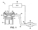
図1に関して、本発明の装置を番号10で示すが、その際、12は軽負荷ディーゼルエンジン本体であり、14はピストンであり、16は燃焼チャンバーであり、18はコモンレール燃料噴射器であり、20は吸気口であり、22は排気口であり、24は吸気バルブであり、26は排気バルブであり、28は排気マニホルドであり、30は排気管であり、32はCSFであり、34は、CSFを収容し、それを排気管と連絡させて保持する排ガスディフューザを備えてなる缶であり、36は、触媒作用を付与した熱電対接合部及び触媒作用を付与していない基準熱電対接合部の両方を備えてなるセンサーであり、38は、使用の際に、センサー36から来る検出入力に応答してCSFの能動的再生の際にコモンレール燃料噴射器を制御するようにプログラム化されたエンジン管理装置(ECU)である。
With respect to FIG. 1, the apparatus of the present invention is designated by the numeral 10, wherein 12 is a light load diesel engine body, 14 is a piston, 16 is a combustion chamber, 18 is a common rail fuel injector, 20 is an intake port, 22 is an exhaust port, 24 is an intake valve, 26 is an exhaust valve, 28 is an exhaust manifold, 30 is an exhaust pipe, 32 is a CSF, 34 is , A can with an exhaust gas diffuser that contains CSF and holds it in communication with the exhaust pipe, 36 is a thermocouple junction with catalytic action and a reference thermocouple junction with no catalytic action The
使用の際、ECU 38は、前回の能動的再生を行って以来の走行距離を測定する。走行距離が予め決められた量、例えば1000 km、を超える場合、ECUが噴射器18を制御し、一連の噴射を開始して温度を増加させ、所望により、CSFに入る排ガスのHCおよび/またはCOを増加させる。ECU 38は、センサー上でHCおよび/またはCOを燃焼させることによる局所的な温度増加に対する、CSFに入る燃焼可能なHCおよび/またはCOの相対的な量を決定するように校正される。一連のルック−アップテーブルまたはマップにより、ECU 38は、検出された量のHCおよび/またはCOの燃焼により引き起こされる、CSF 32で起こりそうな温度上昇を決定し、それに従って、噴射器18を経由する燃焼可能なHCおよび/またはCOの噴射を制御する。
In use,
ECU 38が、CSF 32に入る燃焼可能なHCおよび/またはCOの速度により、予め決められた最高温度、例えば約650℃、を超えるCSF 32の温度上昇を引き起こすと決定した場合、ECU 38は、噴射の速度および/または量を下げる、あるいは、計算された温度が、CSF 32の能動的再生を促進するのに望ましい予め決められた最低閾値、例えば約550℃、未満である場合、ECU 38は、噴射の速度および/または量を増加させる。無論、計算された温度が予め決められた温度範囲内にある場合、CSF温度に影響を及ぼす全てのファクター、例えば加速器の位置、空間速度、等、が実質的に等しいままである限り、噴射の速度および/または量を変化させる必要は無い。当業者は、ECU 38を適切にプログラム化し、所望の閉ループ制御を達成することができるので、これ以上の詳細な説明は行わない。
If
図2に関して、番号100は本発明の第二実施態様を表すが、その際、図1と類似の部品は同じ番号で示す。図2で、110は、短い、例えば長さ2インチ(5 cm)、直径5.6インチ(14.2 cm)の、例えばPt/アルミナの酸化触媒で被覆した基材モノリス(または「スライス」)、例えば400 cpsi(平方インチあたりのセル)(62セル cm−2)である。センサー136は、「スライス」110の直後に配置された触媒作用を付与した熱電対接合部を備えてなり、該センサーは、ECU 38と連絡している。
With reference to FIG. 2, the
使用の際、ある量のHCおよび/またはCOが酸化触媒110の上で燃焼し、その排ガス中で発生した熱が、触媒作用を付与したセンサー自体の上におけるHCおよび/またはCOの燃焼により発生した熱に加えて、センサー136により検出される。排ガス中で検出された温度増加と、CSF中で予想される温度増加とを相関させることができる。
In use, a certain amount of HC and / or CO burns on the
Claims (11)
(a)排ガス触媒作用を付与したフィルター(CSF)と、
排ガスが前記機関の作動中に、前記CSF中に連続的に流れ込んでなるものであり、
(b)制御装置と、
(c)前記CSF中に流れ込む排ガス中の燃焼可能な炭化水素(HC)および/または一酸化炭素(CO)の含有量を増加させ、それによって、前記HCおよび/またはCOを前記CSF中で燃焼させ、前記CSFの温度を増加させ、及び前記CSF上に集められた粒子状物質を燃焼させるための、前記制御装置により制御可能な手段と、及び
(d)前記機関マニホルドと前記CSFとの間に配置された、前記排気機構中を流れる排ガス中のCOおよび/またはHCを燃焼させ、前記制御装置に、前記排ガス中のHCおよび/またはCOの燃焼エンタルピーに相関するデータを入力する、触媒作用を付与したセンサー手段とを備えてなり、
前記触媒作用を付与したセンサー手段が、前記機関と前記CSFとの間に配置された前記排気機構中における唯一の触媒作用を付与した部品であり、
前記制御装置が、使用中に、燃焼可能なHCおよび/またはCOの導入手段を、前記データに応答して制御し、それによって、前記CSFを燃焼可能なHCおよび/またはCOに接触させる速度を制御する、排気機構。 An exhaust mechanism for a lean burn internal combustion engine,
(a) a filter (CSF) provided with exhaust gas catalytic action;
Exhaust gas continuously flows into the CSF during operation of the engine,
(b) a control device;
(c) increasing the content of combustible hydrocarbons (HC) and / or carbon monoxide (CO) in the exhaust gas flowing into the CSF, thereby burning the HC and / or CO in the CSF Means controllable by the controller for increasing the temperature of the CSF and combusting particulate matter collected on the CSF; and
(d) Combusting CO and / or HC in the exhaust gas flowing through the exhaust mechanism disposed between the engine manifold and the CSF, and causing the control device to control the HC and / or CO in the exhaust gas. And a sensor means with catalytic action for inputting data correlated with combustion enthalpy,
The sensor means to which the catalytic action is imparted is a part that imparts the only catalytic action in the exhaust mechanism disposed between the engine and the CSF,
The controller controls the means for introducing combustible HC and / or CO in use in response to the data, thereby controlling the rate at which the CSF contacts the combustible HC and / or CO. Exhaust mechanism to control.
排ガスが前記機関の作動中に、前記CSF中に連続的に流れ込んでなるものであり、
(i)前記CSF中に流れ込む排ガス中にある燃焼可能な炭化水素(HC)および/または一酸化炭素(CO)の含有量を増加させ、それによって、前記HCおよび/またはCOを前記CSF中で燃焼させ、前記CSFの温度を増加し、前記CSF上に集められた粒子状物質を燃焼させることと、
(ii)前記CSFの上流にある排ガス中のHCおよび/またはCOを、触媒作用を付与したセンサー手段上で燃焼させ、前記排ガス中のHCおよび/またはCOの濃度を示す信号を発生させることと、
前記触媒作用を付与したセンサー手段が、前記機関と前記CSFとの間に配置された前記排気機構中における唯一の触媒作用を付与した部品であり、
(iii)前記信号を、前記排ガス中のHCおよび/またはCOの燃焼エンタルピーに関する値と相関させることと、及び
(iv)工程(iii)で決定した前記エンタルピー値に応答して、工程(i)における前記HCおよび/またはCO含有量を制御し、それによって、前記CSFの温度を予め決められた範囲内に維持することとを含んでなる、方法。 A method of controlling active regeneration of a soot filter (CSF) that has been catalyzed by an exhaust mechanism of an internal combustion engine,
Exhaust gas continuously flows into the CSF during operation of the engine,
(i) increasing the content of combustible hydrocarbons (HC) and / or carbon monoxide (CO) in the exhaust gas flowing into the CSF, whereby the HC and / or CO are contained in the CSF. Burning, increasing the temperature of the CSF, and burning particulate matter collected on the CSF;
(ii) combusting HC and / or CO in the exhaust gas upstream of the CSF on a sensor means having a catalytic action to generate a signal indicating the concentration of HC and / or CO in the exhaust gas; ,
The sensor means to which the catalytic action is imparted is a part that imparts the only catalytic action in the exhaust mechanism disposed between the engine and the CSF,
(iii) correlating the signal with a value related to the combustion enthalpy of HC and / or CO in the exhaust gas; and
(iv) in response to the enthalpy value determined in step (iii), controlling the HC and / or CO content in step (i), thereby bringing the temperature of the CSF within a predetermined range. A method comprising: maintaining.
Applications Claiming Priority (3)
| Application Number | Priority Date | Filing Date | Title |
|---|---|---|---|
| GB0603898.8 | 2006-02-28 | ||
| GBGB0603898.8A GB0603898D0 (en) | 2006-02-28 | 2006-02-28 | Exhaust system comprising catalysed soot filter |
| PCT/GB2007/050059 WO2007099363A1 (en) | 2006-02-28 | 2007-02-13 | Exhaust system comprising catalysed soot filter |
Publications (2)
| Publication Number | Publication Date |
|---|---|
| JP2009528476A JP2009528476A (en) | 2009-08-06 |
| JP5324924B2 true JP5324924B2 (en) | 2013-10-23 |
Family
ID=36178850
Family Applications (1)
| Application Number | Title | Priority Date | Filing Date |
|---|---|---|---|
| JP2008556857A Expired - Fee Related JP5324924B2 (en) | 2006-02-28 | 2007-02-13 | Exhaust mechanism with a soot filter with catalytic action |
Country Status (9)
| Country | Link |
|---|---|
| US (1) | US8327632B2 (en) |
| EP (1) | EP1989409B1 (en) |
| JP (1) | JP5324924B2 (en) |
| KR (1) | KR20080114700A (en) |
| CN (1) | CN101395347B (en) |
| AT (1) | ATE530740T1 (en) |
| GB (1) | GB0603898D0 (en) |
| RU (1) | RU2427715C2 (en) |
| WO (1) | WO2007099363A1 (en) |
Families Citing this family (13)
| Publication number | Priority date | Publication date | Assignee | Title |
|---|---|---|---|---|
| EP2123345B1 (en) * | 2008-05-23 | 2010-08-04 | Umicore AG & Co. KG | Device for cleaning diesel exhaust gases |
| JP5062069B2 (en) * | 2008-07-04 | 2012-10-31 | トヨタ自動車株式会社 | Exhaust gas purification device for internal combustion engine |
| US9169765B2 (en) * | 2008-07-14 | 2015-10-27 | Westport Power Inc. | Method for regenerating a diesel particulate filter |
| JP5515553B2 (en) * | 2009-01-16 | 2014-06-11 | トヨタ自動車株式会社 | Temperature sensor and exhaust gas purification device for internal combustion engine |
| KR20110024598A (en) | 2009-09-02 | 2011-03-09 | 현대자동차주식회사 | Nitrogen oxide reduction device of diesel vehicle |
| DE102009046433A1 (en) * | 2009-11-05 | 2011-05-12 | Robert Bosch Gmbh | Method and device for monitoring an emission control system |
| WO2013084019A1 (en) * | 2011-12-09 | 2013-06-13 | Renault Trucks | System for treating the exhaust gases of an internal combustion engine arrangement, and process for controlling an engine arrangement comprising such a system |
| FR2985770B1 (en) * | 2012-01-12 | 2014-03-07 | Renault Sa | OPTIMIZED MANAGEMENT OF A SCR CATALYST BY PERIODIC REGENERATION OF A PARTICLE FILTER |
| CN102841029B (en) * | 2012-09-20 | 2015-04-08 | 奇瑞汽车股份有限公司 | Hydrophobic glass durability test device |
| JP6446445B2 (en) | 2013-10-15 | 2018-12-26 | ジョンソン、マッセイ、パブリック、リミテッド、カンパニーJohnson Matthey Public Limited Company | On-board diagnostic system for catalyzed substrates |
| CN103726907B (en) * | 2014-01-13 | 2015-10-28 | 东南大学 | A kind of flue gas monitoring dust pelletizing system being applied to South Pole scientific investigation support platform diesel generator |
| JP6567900B2 (en) * | 2015-07-02 | 2019-08-28 | 株式会社Soken | Fuel injection control device for internal combustion engine |
| US11492940B2 (en) | 2018-04-27 | 2022-11-08 | Carrier Corporation | Exhaust back pressure and temperature monitoring transport refrigiration unit |
Family Cites Families (40)
| Publication number | Priority date | Publication date | Assignee | Title |
|---|---|---|---|---|
| DE2202614A1 (en) * | 1972-01-20 | 1973-08-02 | Bosch Gmbh Robert | EXHAUST GAS AFTER-COMBUSTION DEVICE |
| DE2330749A1 (en) | 1972-05-26 | 1975-01-09 | Volkswagenwerk Ag | IC engine exhaust cleaning reactor - has differential temp detector for control, constructed as single component |
| US4029472A (en) * | 1976-04-05 | 1977-06-14 | General Motors Corporation | Thermoelectric exhaust gas sensor |
| DE2643739C2 (en) | 1976-09-29 | 1986-03-13 | Robert Bosch Gmbh, 7000 Stuttgart | Method for monitoring the activity of catalytic converters for exhaust gas purification |
| DE4022546A1 (en) | 1990-07-16 | 1992-01-23 | Emitec Emissionstechnologie | Sensor device for monitoring vehicle exhaust systems - uses two temp.-sensors, one of which is coated with catalyst to promote oxidn. of hydrocarbon(s) and carbon mon:oxide |
| US5363091A (en) | 1991-08-07 | 1994-11-08 | Ford Motor Company | Catalyst monitoring using ego sensors |
| JPH0544434A (en) * | 1991-08-08 | 1993-02-23 | Nissan Motor Co Ltd | Exhaust gas treating device for internal combustion engine |
| US6242263B1 (en) * | 1996-12-20 | 2001-06-05 | Corning Incorporated | Automotive hydrocarbon sensor |
| US6037183A (en) | 1996-12-20 | 2000-03-14 | Corning Incorporated | Automotive hydrocarbon sensor system |
| JPH10252450A (en) | 1997-03-15 | 1998-09-22 | Toyota Central Res & Dev Lab Inc | Apparatus for detecting combustible components in exhaust gas and apparatus for determining catalytic activity ability |
| JP3876506B2 (en) | 1997-06-20 | 2007-01-31 | 株式会社デンソー | Gas concentration measuring method and composite gas sensor |
| US5941918A (en) * | 1997-07-30 | 1999-08-24 | Engelhard Corporation | Automotive on-board monitoring system for catalytic converter evaluation |
| US6546721B2 (en) * | 2000-04-18 | 2003-04-15 | Toyota Jidosha Kabushiki Kaisha | Exhaust gas purification device |
| US6826906B2 (en) * | 2000-08-15 | 2004-12-07 | Engelhard Corporation | Exhaust system for enhanced reduction of nitrogen oxides and particulates from diesel engines |
| JP4161546B2 (en) * | 2001-06-26 | 2008-10-08 | いすゞ自動車株式会社 | Regeneration control method for continuous regeneration type diesel particulate filter device |
| JP3599012B2 (en) * | 2001-10-01 | 2004-12-08 | トヨタ自動車株式会社 | Exhaust gas purification device for internal combustion engine |
| JP3835241B2 (en) * | 2001-10-15 | 2006-10-18 | トヨタ自動車株式会社 | Exhaust gas purification device for internal combustion engine |
| FR2832183B1 (en) * | 2001-11-13 | 2005-10-28 | Peugeot Citroen Automobiles Sa | SYSTEM FOR AIDING THE REGENERATION OF A CATALYSIS PARTICLE FILTER ARRANGED IN A DIESEL ENGINE EXHAUST LINE OF A MOTOR VEHICLE |
| US6915629B2 (en) * | 2002-03-07 | 2005-07-12 | General Motors Corporation | After-treatment system and method for reducing emissions in diesel engine exhaust |
| US6810660B2 (en) * | 2002-04-08 | 2004-11-02 | Ford Global Technologies, Llc | System for minimizing the impact of poisoning of automotive exhaust aftertreatment systems |
| JP3757894B2 (en) * | 2002-04-15 | 2006-03-22 | トヨタ自動車株式会社 | Exhaust purification device for internal combustion engine and exhaust purification method for internal combustion engine |
| US6826905B2 (en) * | 2002-06-04 | 2004-12-07 | International Engine Intellectual Property Company, Llc | Control strategy for regenerating a particulate filter in an exhaust system of an engine having a variable valve actuation mechanism |
| JP4045935B2 (en) * | 2002-11-25 | 2008-02-13 | 三菱ふそうトラック・バス株式会社 | Exhaust gas purification device for internal combustion engine |
| GB0304939D0 (en) * | 2003-03-05 | 2003-04-09 | Johnson Matthey Plc | Light-duty diesel engine and a particulate filter therefor |
| GB0305415D0 (en) * | 2003-03-08 | 2003-04-16 | Johnson Matthey Plc | Exhaust system for lean burn IC engine including particulate filter and NOx absorbent |
| FR2854923B1 (en) | 2003-05-12 | 2006-06-23 | Peugeot Citroen Automobiles Sa | SYSTEM FOR AIDING THE REGENERATION OF A NOx TRAP |
| JP4345359B2 (en) * | 2003-05-28 | 2009-10-14 | いすゞ自動車株式会社 | Exhaust gas purification system |
| JP4333289B2 (en) * | 2003-09-03 | 2009-09-16 | いすゞ自動車株式会社 | Exhaust gas purification system |
| DE602004004221T2 (en) * | 2003-09-19 | 2007-05-03 | Nissan Motor Co., Ltd., Yokohama | Regeneration control of a filter |
| US6978604B2 (en) * | 2003-11-06 | 2005-12-27 | International Engine Intellectual Property Company, Llc | Soot burn-off control strategy for a catalyzed diesel particulate filter |
| JP2005248787A (en) | 2004-03-03 | 2005-09-15 | Mitsubishi Fuso Truck & Bus Corp | Exhaust cleaner |
| JP4507697B2 (en) * | 2004-05-21 | 2010-07-21 | トヨタ自動車株式会社 | Exhaust gas purification system for internal combustion engine |
| DE102004027907A1 (en) * | 2004-06-09 | 2005-12-29 | Emitec Gesellschaft Für Emissionstechnologie Mbh | Control system for a mobile internal combustion engine |
| DE102004033412A1 (en) * | 2004-07-10 | 2006-02-02 | Robert Bosch Gmbh | Method for operating a particulate filter arranged in an exhaust area of an internal combustion engine and device for carrying out the method |
| DE102004046638A1 (en) * | 2004-09-25 | 2006-03-30 | Robert Bosch Gmbh | Method for operating particle filter in exhaust of internal combustion engine involves blowing secondary air stream into exhaust area upstream of filter in dependence on particle burn-off speed |
| DE102004048336A1 (en) * | 2004-10-01 | 2006-04-13 | J. Eberspächer GmbH & Co. KG | Exhaust system for an internal combustion engine |
| GB2406803A (en) | 2004-11-23 | 2005-04-13 | Johnson Matthey Plc | Exhaust system comprising exotherm-generating catalyst |
| US7533524B2 (en) * | 2005-05-18 | 2009-05-19 | Cummins Inc. | Method and apparatus for soot filter catalyst temperature control with oxygen flow constraint |
| US7299626B2 (en) * | 2005-09-01 | 2007-11-27 | International Engine Intellectual Property Company, Llc | DPF regeneration monitoring method |
| GB0716833D0 (en) | 2007-08-31 | 2007-10-10 | Nunn Andrew D | On board diagnostic system |
-
2006
- 2006-02-28 GB GBGB0603898.8A patent/GB0603898D0/en not_active Ceased
-
2007
- 2007-02-13 RU RU2008138547/06A patent/RU2427715C2/en active
- 2007-02-13 JP JP2008556857A patent/JP5324924B2/en not_active Expired - Fee Related
- 2007-02-13 WO PCT/GB2007/050059 patent/WO2007099363A1/en not_active Ceased
- 2007-02-13 US US12/280,932 patent/US8327632B2/en not_active Expired - Fee Related
- 2007-02-13 EP EP07705372A patent/EP1989409B1/en not_active Not-in-force
- 2007-02-13 AT AT07705372T patent/ATE530740T1/en not_active IP Right Cessation
- 2007-02-13 KR KR1020087021001A patent/KR20080114700A/en not_active Ceased
- 2007-02-13 CN CN2007800070572A patent/CN101395347B/en not_active Expired - Fee Related
Also Published As
| Publication number | Publication date |
|---|---|
| US8327632B2 (en) | 2012-12-11 |
| EP1989409B1 (en) | 2011-10-26 |
| RU2008138547A (en) | 2010-04-10 |
| EP1989409A1 (en) | 2008-11-12 |
| WO2007099363A1 (en) | 2007-09-07 |
| RU2427715C2 (en) | 2011-08-27 |
| US20090071131A1 (en) | 2009-03-19 |
| GB0603898D0 (en) | 2006-04-05 |
| CN101395347B (en) | 2012-12-26 |
| JP2009528476A (en) | 2009-08-06 |
| CN101395347A (en) | 2009-03-25 |
| KR20080114700A (en) | 2008-12-31 |
| ATE530740T1 (en) | 2011-11-15 |
Similar Documents
| Publication | Publication Date | Title |
|---|---|---|
| JP5324924B2 (en) | Exhaust mechanism with a soot filter with catalytic action | |
| JP5383615B2 (en) | Warming up the aftertreatment burner system | |
| CN102822481A (en) | Regeneration assist calibration | |
| US20120144802A1 (en) | Exhaust system having doc regeneration strategy | |
| US9194272B2 (en) | Power system | |
| US20090000604A1 (en) | Engine system having aftertreatment and an intake air heater | |
| US7654079B2 (en) | Diesel oxidation catalyst filter heating system | |
| CN102803674A (en) | Internal combustion engine | |
| US9523974B2 (en) | Method of controlling operation of an exhaust fluid treatment apparatus | |
| US9260996B2 (en) | Exhaust system and method for controlling an exhaust system | |
| US8864875B2 (en) | Regeneration of a particulate filter based on a particulate matter oxidation rate | |
| JP5141824B2 (en) | Exhaust gas purification device for internal combustion engine | |
| US8881503B2 (en) | Method and device for preventing fuel freezing in a postprocessing burner system | |
| US8584445B2 (en) | Method and system for controlling an electrically heated particulate filter | |
| Joshi et al. | Development of an actively regenerating DPF system for retrofit applications | |
| US7204082B1 (en) | System for combustion of reformate in an engine exhaust stream | |
| JP2009299617A (en) | Exhaust emission control device for internal combustion engine | |
| US20090070003A1 (en) | Device for controlling the operating state of a catalytic converter of an exhaust line pertaining to an internal combustion engine, and engine comprising one such device | |
| KR20120036008A (en) | Vehicle emission purification system | |
| KR102241485B1 (en) | System for controlling forced regeneration | |
| EP2559871A1 (en) | Combustion/temperature increase control method and device for after-treatment burner system | |
| JP5387984B2 (en) | Internal combustion engine | |
| JP2018048568A (en) | Internal combustion engine and method for increasing temperature of exhaust gas thereof |
Legal Events
| Date | Code | Title | Description |
|---|---|---|---|
| A621 | Written request for application examination |
Free format text: JAPANESE INTERMEDIATE CODE: A621 Effective date: 20100119 |
|
| A977 | Report on retrieval |
Free format text: JAPANESE INTERMEDIATE CODE: A971007 Effective date: 20111025 |
|
| A131 | Notification of reasons for refusal |
Free format text: JAPANESE INTERMEDIATE CODE: A131 Effective date: 20111104 |
|
| A601 | Written request for extension of time |
Free format text: JAPANESE INTERMEDIATE CODE: A601 Effective date: 20120206 |
|
| A602 | Written permission of extension of time |
Free format text: JAPANESE INTERMEDIATE CODE: A602 Effective date: 20120213 |
|
| A601 | Written request for extension of time |
Free format text: JAPANESE INTERMEDIATE CODE: A601 Effective date: 20120305 |
|
| A602 | Written permission of extension of time |
Free format text: JAPANESE INTERMEDIATE CODE: A602 Effective date: 20120312 |
|
| A521 | Request for written amendment filed |
Free format text: JAPANESE INTERMEDIATE CODE: A523 Effective date: 20120404 |
|
| A131 | Notification of reasons for refusal |
Free format text: JAPANESE INTERMEDIATE CODE: A131 Effective date: 20121026 |
|
| RD03 | Notification of appointment of power of attorney |
Free format text: JAPANESE INTERMEDIATE CODE: A7423 Effective date: 20130125 |
|
| RD04 | Notification of resignation of power of attorney |
Free format text: JAPANESE INTERMEDIATE CODE: A7424 Effective date: 20130214 |
|
| TRDD | Decision of grant or rejection written | ||
| A01 | Written decision to grant a patent or to grant a registration (utility model) |
Free format text: JAPANESE INTERMEDIATE CODE: A01 Effective date: 20130716 |
|
| A61 | First payment of annual fees (during grant procedure) |
Free format text: JAPANESE INTERMEDIATE CODE: A61 Effective date: 20130719 |
|
| R150 | Certificate of patent or registration of utility model |
Ref document number: 5324924 Country of ref document: JP Free format text: JAPANESE INTERMEDIATE CODE: R150 Free format text: JAPANESE INTERMEDIATE CODE: R150 |
|
| R250 | Receipt of annual fees |
Free format text: JAPANESE INTERMEDIATE CODE: R250 |
|
| R250 | Receipt of annual fees |
Free format text: JAPANESE INTERMEDIATE CODE: R250 |
|
| R250 | Receipt of annual fees |
Free format text: JAPANESE INTERMEDIATE CODE: R250 |
|
| R250 | Receipt of annual fees |
Free format text: JAPANESE INTERMEDIATE CODE: R250 |
|
| R250 | Receipt of annual fees |
Free format text: JAPANESE INTERMEDIATE CODE: R250 |
|
| R250 | Receipt of annual fees |
Free format text: JAPANESE INTERMEDIATE CODE: R250 |
|
| R250 | Receipt of annual fees |
Free format text: JAPANESE INTERMEDIATE CODE: R250 |
|
| LAPS | Cancellation because of no payment of annual fees |