JP4345359B2 - Exhaust gas purification system - Google Patents
Exhaust gas purification system Download PDFInfo
- Publication number
- JP4345359B2 JP4345359B2 JP2003151113A JP2003151113A JP4345359B2 JP 4345359 B2 JP4345359 B2 JP 4345359B2 JP 2003151113 A JP2003151113 A JP 2003151113A JP 2003151113 A JP2003151113 A JP 2003151113A JP 4345359 B2 JP4345359 B2 JP 4345359B2
- Authority
- JP
- Japan
- Prior art keywords
- exhaust
- temperature
- oxidation catalyst
- exhaust gas
- determination
- Prior art date
- Legal status (The legal status is an assumption and is not a legal conclusion. Google has not performed a legal analysis and makes no representation as to the accuracy of the status listed.)
- Expired - Fee Related
Links
Images


Classifications
-
- F—MECHANICAL ENGINEERING; LIGHTING; HEATING; WEAPONS; BLASTING
- F01—MACHINES OR ENGINES IN GENERAL; ENGINE PLANTS IN GENERAL; STEAM ENGINES
- F01N—GAS-FLOW SILENCERS OR EXHAUST APPARATUS FOR MACHINES OR ENGINES IN GENERAL; GAS-FLOW SILENCERS OR EXHAUST APPARATUS FOR INTERNAL COMBUSTION ENGINES
- F01N9/00—Electrical control of exhaust gas treating apparatus
- F01N9/002—Electrical control of exhaust gas treating apparatus of filter regeneration, e.g. detection of clogging
-
- F—MECHANICAL ENGINEERING; LIGHTING; HEATING; WEAPONS; BLASTING
- F01—MACHINES OR ENGINES IN GENERAL; ENGINE PLANTS IN GENERAL; STEAM ENGINES
- F01N—GAS-FLOW SILENCERS OR EXHAUST APPARATUS FOR MACHINES OR ENGINES IN GENERAL; GAS-FLOW SILENCERS OR EXHAUST APPARATUS FOR INTERNAL COMBUSTION ENGINES
- F01N13/00—Exhaust or silencing apparatus characterised by constructional features ; Exhaust or silencing apparatus, or parts thereof, having pertinent characteristics not provided for in, or of interest apart from, groups F01N1/00 - F01N5/00, F01N9/00, F01N11/00
- F01N13/009—Exhaust or silencing apparatus characterised by constructional features ; Exhaust or silencing apparatus, or parts thereof, having pertinent characteristics not provided for in, or of interest apart from, groups F01N1/00 - F01N5/00, F01N9/00, F01N11/00 having two or more separate purifying devices arranged in series
- F01N13/0097—Exhaust or silencing apparatus characterised by constructional features ; Exhaust or silencing apparatus, or parts thereof, having pertinent characteristics not provided for in, or of interest apart from, groups F01N1/00 - F01N5/00, F01N9/00, F01N11/00 having two or more separate purifying devices arranged in series the purifying devices are arranged in a single housing
-
- F—MECHANICAL ENGINEERING; LIGHTING; HEATING; WEAPONS; BLASTING
- F01—MACHINES OR ENGINES IN GENERAL; ENGINE PLANTS IN GENERAL; STEAM ENGINES
- F01N—GAS-FLOW SILENCERS OR EXHAUST APPARATUS FOR MACHINES OR ENGINES IN GENERAL; GAS-FLOW SILENCERS OR EXHAUST APPARATUS FOR INTERNAL COMBUSTION ENGINES
- F01N3/00—Exhaust or silencing apparatus having means for purifying, rendering innocuous, or otherwise treating exhaust
- F01N3/02—Exhaust or silencing apparatus having means for purifying, rendering innocuous, or otherwise treating exhaust for cooling, or for removing solid constituents of, exhaust
- F01N3/021—Exhaust or silencing apparatus having means for purifying, rendering innocuous, or otherwise treating exhaust for cooling, or for removing solid constituents of, exhaust by means of filters
- F01N3/023—Exhaust or silencing apparatus having means for purifying, rendering innocuous, or otherwise treating exhaust for cooling, or for removing solid constituents of, exhaust by means of filters using means for regenerating the filters, e.g. by burning trapped particles
- F01N3/0231—Exhaust or silencing apparatus having means for purifying, rendering innocuous, or otherwise treating exhaust for cooling, or for removing solid constituents of, exhaust by means of filters using means for regenerating the filters, e.g. by burning trapped particles using special exhaust apparatus upstream of the filter for producing nitrogen dioxide, e.g. for continuous filter regeneration systems [CRT]
-
- F—MECHANICAL ENGINEERING; LIGHTING; HEATING; WEAPONS; BLASTING
- F01—MACHINES OR ENGINES IN GENERAL; ENGINE PLANTS IN GENERAL; STEAM ENGINES
- F01N—GAS-FLOW SILENCERS OR EXHAUST APPARATUS FOR MACHINES OR ENGINES IN GENERAL; GAS-FLOW SILENCERS OR EXHAUST APPARATUS FOR INTERNAL COMBUSTION ENGINES
- F01N3/00—Exhaust or silencing apparatus having means for purifying, rendering innocuous, or otherwise treating exhaust
- F01N3/02—Exhaust or silencing apparatus having means for purifying, rendering innocuous, or otherwise treating exhaust for cooling, or for removing solid constituents of, exhaust
- F01N3/021—Exhaust or silencing apparatus having means for purifying, rendering innocuous, or otherwise treating exhaust for cooling, or for removing solid constituents of, exhaust by means of filters
- F01N3/023—Exhaust or silencing apparatus having means for purifying, rendering innocuous, or otherwise treating exhaust for cooling, or for removing solid constituents of, exhaust by means of filters using means for regenerating the filters, e.g. by burning trapped particles
- F01N3/0235—Exhaust or silencing apparatus having means for purifying, rendering innocuous, or otherwise treating exhaust for cooling, or for removing solid constituents of, exhaust by means of filters using means for regenerating the filters, e.g. by burning trapped particles using exhaust gas throttling means
-
- F—MECHANICAL ENGINEERING; LIGHTING; HEATING; WEAPONS; BLASTING
- F02—COMBUSTION ENGINES; HOT-GAS OR COMBUSTION-PRODUCT ENGINE PLANTS
- F02B—INTERNAL-COMBUSTION PISTON ENGINES; COMBUSTION ENGINES IN GENERAL
- F02B37/00—Engines characterised by provision of pumps driven at least for part of the time by exhaust
-
- F—MECHANICAL ENGINEERING; LIGHTING; HEATING; WEAPONS; BLASTING
- F02—COMBUSTION ENGINES; HOT-GAS OR COMBUSTION-PRODUCT ENGINE PLANTS
- F02D—CONTROLLING COMBUSTION ENGINES
- F02D41/00—Electrical control of supply of combustible mixture or its constituents
- F02D41/02—Circuit arrangements for generating control signals
- F02D41/021—Introducing corrections for particular conditions exterior to the engine
- F02D41/0235—Introducing corrections for particular conditions exterior to the engine in relation with the state of the exhaust gas treating apparatus
- F02D41/027—Introducing corrections for particular conditions exterior to the engine in relation with the state of the exhaust gas treating apparatus to purge or regenerate the exhaust gas treating apparatus
- F02D41/029—Introducing corrections for particular conditions exterior to the engine in relation with the state of the exhaust gas treating apparatus to purge or regenerate the exhaust gas treating apparatus the exhaust gas treating apparatus being a particulate filter
-
- F—MECHANICAL ENGINEERING; LIGHTING; HEATING; WEAPONS; BLASTING
- F02—COMBUSTION ENGINES; HOT-GAS OR COMBUSTION-PRODUCT ENGINE PLANTS
- F02D—CONTROLLING COMBUSTION ENGINES
- F02D41/00—Electrical control of supply of combustible mixture or its constituents
- F02D41/30—Controlling fuel injection
- F02D41/38—Controlling fuel injection of the high pressure type
- F02D41/40—Controlling fuel injection of the high pressure type with means for controlling injection timing or duration
- F02D41/401—Controlling injection timing
-
- F—MECHANICAL ENGINEERING; LIGHTING; HEATING; WEAPONS; BLASTING
- F02—COMBUSTION ENGINES; HOT-GAS OR COMBUSTION-PRODUCT ENGINE PLANTS
- F02D—CONTROLLING COMBUSTION ENGINES
- F02D41/00—Electrical control of supply of combustible mixture or its constituents
- F02D41/30—Controlling fuel injection
- F02D41/38—Controlling fuel injection of the high pressure type
- F02D41/40—Controlling fuel injection of the high pressure type with means for controlling injection timing or duration
- F02D41/402—Multiple injections
- F02D41/403—Multiple injections with pilot injections
-
- F—MECHANICAL ENGINEERING; LIGHTING; HEATING; WEAPONS; BLASTING
- F01—MACHINES OR ENGINES IN GENERAL; ENGINE PLANTS IN GENERAL; STEAM ENGINES
- F01N—GAS-FLOW SILENCERS OR EXHAUST APPARATUS FOR MACHINES OR ENGINES IN GENERAL; GAS-FLOW SILENCERS OR EXHAUST APPARATUS FOR INTERNAL COMBUSTION ENGINES
- F01N2250/00—Combinations of different methods of purification
- F01N2250/02—Combinations of different methods of purification filtering and catalytic conversion
-
- F—MECHANICAL ENGINEERING; LIGHTING; HEATING; WEAPONS; BLASTING
- F01—MACHINES OR ENGINES IN GENERAL; ENGINE PLANTS IN GENERAL; STEAM ENGINES
- F01N—GAS-FLOW SILENCERS OR EXHAUST APPARATUS FOR MACHINES OR ENGINES IN GENERAL; GAS-FLOW SILENCERS OR EXHAUST APPARATUS FOR INTERNAL COMBUSTION ENGINES
- F01N2430/00—Influencing exhaust purification, e.g. starting of catalytic reaction, filter regeneration, or the like, by controlling engine operating characteristics
- F01N2430/08—Influencing exhaust purification, e.g. starting of catalytic reaction, filter regeneration, or the like, by controlling engine operating characteristics by modifying ignition or injection timing
- F01N2430/085—Influencing exhaust purification, e.g. starting of catalytic reaction, filter regeneration, or the like, by controlling engine operating characteristics by modifying ignition or injection timing at least a part of the injection taking place during expansion or exhaust stroke
-
- F—MECHANICAL ENGINEERING; LIGHTING; HEATING; WEAPONS; BLASTING
- F01—MACHINES OR ENGINES IN GENERAL; ENGINE PLANTS IN GENERAL; STEAM ENGINES
- F01N—GAS-FLOW SILENCERS OR EXHAUST APPARATUS FOR MACHINES OR ENGINES IN GENERAL; GAS-FLOW SILENCERS OR EXHAUST APPARATUS FOR INTERNAL COMBUSTION ENGINES
- F01N2510/00—Surface coverings
- F01N2510/06—Surface coverings for exhaust purification, e.g. catalytic reaction
- F01N2510/065—Surface coverings for exhaust purification, e.g. catalytic reaction for reducing soot ignition temperature
-
- F—MECHANICAL ENGINEERING; LIGHTING; HEATING; WEAPONS; BLASTING
- F02—COMBUSTION ENGINES; HOT-GAS OR COMBUSTION-PRODUCT ENGINE PLANTS
- F02D—CONTROLLING COMBUSTION ENGINES
- F02D2200/00—Input parameters for engine control
- F02D2200/02—Input parameters for engine control the parameters being related to the engine
- F02D2200/08—Exhaust gas treatment apparatus parameters
- F02D2200/0802—Temperature of the exhaust gas treatment apparatus
-
- F—MECHANICAL ENGINEERING; LIGHTING; HEATING; WEAPONS; BLASTING
- F02—COMBUSTION ENGINES; HOT-GAS OR COMBUSTION-PRODUCT ENGINE PLANTS
- F02D—CONTROLLING COMBUSTION ENGINES
- F02D41/00—Electrical control of supply of combustible mixture or its constituents
- F02D41/30—Controlling fuel injection
- F02D41/38—Controlling fuel injection of the high pressure type
- F02D41/40—Controlling fuel injection of the high pressure type with means for controlling injection timing or duration
- F02D41/402—Multiple injections
-
- Y—GENERAL TAGGING OF NEW TECHNOLOGICAL DEVELOPMENTS; GENERAL TAGGING OF CROSS-SECTIONAL TECHNOLOGIES SPANNING OVER SEVERAL SECTIONS OF THE IPC; TECHNICAL SUBJECTS COVERED BY FORMER USPC CROSS-REFERENCE ART COLLECTIONS [XRACs] AND DIGESTS
- Y02—TECHNOLOGIES OR APPLICATIONS FOR MITIGATION OR ADAPTATION AGAINST CLIMATE CHANGE
- Y02T—CLIMATE CHANGE MITIGATION TECHNOLOGIES RELATED TO TRANSPORTATION
- Y02T10/00—Road transport of goods or passengers
- Y02T10/10—Internal combustion engine [ICE] based vehicles
- Y02T10/12—Improving ICE efficiencies
-
- Y—GENERAL TAGGING OF NEW TECHNOLOGICAL DEVELOPMENTS; GENERAL TAGGING OF CROSS-SECTIONAL TECHNOLOGIES SPANNING OVER SEVERAL SECTIONS OF THE IPC; TECHNICAL SUBJECTS COVERED BY FORMER USPC CROSS-REFERENCE ART COLLECTIONS [XRACs] AND DIGESTS
- Y02—TECHNOLOGIES OR APPLICATIONS FOR MITIGATION OR ADAPTATION AGAINST CLIMATE CHANGE
- Y02T—CLIMATE CHANGE MITIGATION TECHNOLOGIES RELATED TO TRANSPORTATION
- Y02T10/00—Road transport of goods or passengers
- Y02T10/10—Internal combustion engine [ICE] based vehicles
- Y02T10/40—Engine management systems
Description
【0001】
【発明の属する技術分野】
本発明は、連続再生型ディーゼルパティキュレートフィルタを備えて、エンジンの排気ガスを浄化する排気ガス浄化システムに関する。
【0002】
【従来の技術】
ディーゼルエンジンから排出される粒子状物質(PM:パティキュレート・マター:以下PMとする)の排出量は、NOx,COそしてHC等と共に年々規制が強化されてきており、規制の強化に伴いエンジンの改良のみでは、対応できなくなってきている。そこで、エンジンから排出されるPMをディーゼルパティキュレートフィルタ(DPF:Diesel Particulate Filter :以下DPFとする)と呼ばれるフィルタで捕集して、外部へ排出されるPMの量を低減する技術が開発されている。
【0003】
直接、このPMを捕集するDPFにはセラミック製のモノリスハニカム型ウオールフロータイプのフィルタや、セラミックや金属を繊維状にした繊維型タイプのフィルタ等があり、これらのDPFを用いた排気ガス浄化システムは、他の排気ガス浄化システムと同様に、エンジンの排気通路の途中に設置され、エンジンで発生する排気ガスを浄化している。
【0004】
DPFはフィルタがPMを捕集すると捕集量に比例して排圧が上昇するので、捕集されたPMを燃焼させるなどして除去し、DPFを再生する必要がある。この再生方法には色々な方法が提案されており、電気ヒーター加熱タイプ、バーナー加熱タイプ、逆洗タイプ等がある。
【0005】
しかしながら、これらの再生方法をとる場合には、外部からエネルギーの供給を受けてPMの燃焼を行うので、燃費の悪化を招き、また、再生時の制御が難しく、PM捕集、PM燃焼(DPF再生)を交互に行うような二系統のDPFシステムが必要になる等、システムが大きく複雑になるという問題がある。
【0006】
この問題を解決するために、酸化触媒を利用しPMの酸化温度を下げ、外部からエネルギーを受けることなく、エンジンからの排気熱でPMを酸化してDPFを再生する技術が提案されている。この場合には、DPF再生が基本的には連続的になるため連続再生型DPFシステムと呼ばれているが、これらのシステムは、より簡素化された一系統のDPFシステムとなり、再生制御も簡素化されるという利点がある。
【0007】
図8に一例として示すNO2 再生型DPFシステム1Xは、NO2 (二酸化窒素)によりPMを酸化して、DPFを再生するシステムであり、通常のウオールフローフィルタ3Abの上流に酸化触媒3Aaを配置し、排気ガス中のNO(一酸化窒素)を酸化する。従って、酸化触媒3Aa後流の排気ガス中のNOxは殆どがNO2 になる。このNO2 で、下流側のフィルタ3Abに捕集されたPMを酸化してCO2 (二酸化炭素)とし、PMを除去している。このNO2 は、O2 よりエネルギー障壁が小さいため、PM酸化温度(DPF再生温度)を低下させるので、外部からエネルギーの供給なしに排気ガス中の熱エネルギーで連続的にPM燃焼が生じる。
【0008】
なお、図8のEはディーゼルエンジン、2は排気通路、4は燃料ポンプシステム、5は電子制御ボックス、7はバッテリー、8は消音器、9は燃料タンクである。
【0009】
また、図9に、図8のNO2 再生型DPFシステムの改良システム1Yを示す。この改良システム1Yは、酸化触媒32Aの多孔質触媒コート層31をウオールフローフィルタ3Bの多孔質壁面30に塗布し、NOの酸化とこれにより発生したNO2 によるPMの酸化を、ウオールフローフィルタ3Bの壁表面上で行うように構成し、システムを簡素化している。
【0010】
そして、図10に、ウオールフローフィルタ3Cの多孔質壁面30に、酸化触媒32Aと酸化物等のPM酸化触媒32Bとの多孔質触媒コート層31を塗布し、フィルタ3Cに蓄積したPMを低温で燃焼し、連続再生するシステム1Zを示す。
【0011】
そして、これらの触媒付きDPFシステムは、触媒及びNO2 によるPMの酸化反応によって通常のフィルタよりもPM酸化開始温度を下げてPMの連続再生を実現するシステムである。
【0012】
しかし、PM酸化開始温度を下げても、まだ、350℃程度の排気温度は必要であるため、低負荷運転やアイドル運転等では、排気温度が低いため、PMの酸化及びDPFの自己再生が生じない。従って、このようなアイドルや低負荷等の排気温度が低いエンジン運転状態が継続するとPMが蓄積してもPM酸化状態にならないため、排圧が上昇し、燃費の悪化を招き、また、エンジン停止等のトラブルが生じるおそれがある。
【0013】
そこで、これらの連続再生型DPFシステムでは、エンジン運転条件からフィルタへのPM蓄積量を算出したり、又は、PM蓄積量に対応したフィルタ圧損からPM蓄積量を推定したりして、DPF再生必要条件を設定し、このDPF再生必要条件を満たした時に、排気温度を強制的に上昇させて、蓄積したPMを強制的に燃焼させて除去するDPF再生制御を行っている。
【0014】
そして、連続再生型DPFシステムでは、PMを強制的に燃焼させるために、コモンレール等の電子制御式燃料噴射システムを使用して、主噴射の前段に行う少噴射量の多段噴射と主噴射の過大な遅延の組合せによる遅延多段噴射で、排気温度を酸化触媒の活性温度以上に上昇させた後、通常の噴射制御に戻して、ポスト噴射又は排気管内噴射等で軽油等の燃料(HC)を排気管内に追加し、この燃料を上流側の酸化触媒で燃焼させ、下流側のフィルタへ流入する排気ガスの温度を蓄積されたPMが強制的に燃焼する温度以上に昇温し、これにより蓄積されたPMを強制燃焼し除去している。
【0015】
また、多段噴射で排気ガスの昇温を行うと共に、排気絞りを併用することにより、エンジンの排圧を上昇させて吸気行程に残留する排気ガスの増量と昇温を図り、この排気ガスの高温化によって噴射燃料の着火性、燃焼性能を向上させることにより排気温度を上昇させる方法も提案されている。
【0016】
この方法の一つとして、トラップフィルタ(DPF)の下流側に排気絞り弁を設けて、フィルタ再生中に排気温度を所定の再生温度範囲に保つように、つまり、DPFの入口排気温度が所定温度になるように、排気絞り弁の弁開度を制御するディーゼルエンジンの排気浄化装置が提案されている(例えば、特許文献1参照。)。
【0017】
【特許文献1】
特開平04−81513号公報
【0018】
【発明が解決しようとする課題】
しかしながら、これらの排気絞り併用の多段噴射を使用した従来技術におけるDPF再生制御では、再生制御運転におけるトルク変動が大きくなってしまうという問題と白煙の発生という問題がある。
【0019】
つまり、再生制御運転時において、排気絞り併用の多段噴射により排気温度を酸化触媒の活性温度以上に上昇させた後は、通常の噴射制御に戻しているため、この排気絞り併用の多段噴射から通常の噴射制御に戻す時に、排圧の急変によるトルク変動と噴射時期の大きな変化によるトルク変動とが生じる。また、酸化触媒に入る排気温度が通常噴射で低下し、通常の噴射制御から再び排気絞り併用の多段噴射に戻す必要が生じる場合があるが、この場合もトルク変動が生じる。
【0020】
また、排気絞り併用の多段噴射から通常の噴射制御への切り替え時における噴射量の変化に起因してHC、白煙の発生が生じる場合がある。
【0021】
本発明は、上述の問題を解決するべくなされたものであり、その目的は、連続再生型DPFにおいて、DPF再生のための再生制御運転において、トルク変動が少なく、白煙の発生も防止できる排気ガス浄化システムを提供することにある。
【0022】
【課題を解決するための手段】
以上のような目的を達成するための排気ガス浄化システムは、内燃機関の排気通路に上流側から酸化触媒と粒子状物質を捕集するフィルタを備え、前記酸化触媒の上流側又は前記フィルタの下流側に排気絞り弁を設けると共に、前記酸化触媒の入口に第1排気温度センサを、前記酸化触媒と前記フィルタの間に第2排気温度センサを配設した排気ガス浄化システムにおいて、前記DPFの再生制御の際に、前記第1排気温度センサで検出した排気温度が、所定の第1判定温度以下である時に、前記排気絞り弁を閉じてパイロット噴射を含む遅延多段噴射制御を行い、排気ガスを前記酸化触媒の活性温度とする第2判定温度になるまで昇温させると共に、前記第1排気温度センサで検出した排気温度が前記第2判定温度になった場合、前記第2排気温度センサで検出した排気温度が所定の第3判定温度以下であるときに、前記排気絞り弁を段階的若しくは連続的に開いて遅延多段噴射制御を行うように構成される。
【0023】
この構成によれば、DPFの再生制御において、酸化触媒入口の排気温度が、酸化触媒の活性温度等の第1判定温度より低い場合に、排気温度を昇温させる時に、排気絞りにより、最初に噴射される噴射時期の失火限界を大幅に遅延可能にすると共に、噴射量を増強可能にし、大きな初期発生火炎を作り、その後の火炎伝播力を向上させ、希薄混合気まで完全に燃焼させることができるので、白煙の発生や失火が防止され、効率よく排気温度を大幅に上昇することができる。
【0024】
そして、酸化触媒入口の排気温度が酸化触媒の活性温度等の第2判定温度以上になった場合でも、通常の噴射制御に戻さずに、排気絞り併用の遅延多段噴射を継続させて、排気絞り弁の開度を段階的又は連続的に調整することにより、燃焼室内の燃焼状態を制御して、酸化触媒で燃焼させるHCの排気ガス中への供給量を調整し、これによりDPF入口の排気温度を制御するので、排圧の急激な変化や噴射時期の急激な変化や噴射量の急激な変化を回避でき、出力トルクの変動や白煙の発生を防止できる。
【0025】
そして、上記の排気ガス浄化システムにおいて、前記酸化触媒の入口の排気温度が前記第2判定温度以上に昇温した後に、前記第2排気温度センサで検出した排気温度が前記第3判定温度以上になった場合には、前記排気絞り弁を段階的若しくは連続的に閉じるように構成される。また、前記酸化触媒の入口の排気温度が前記第2判定温度以上に昇温した後に、前記第2排気温度センサで検出した排気温度が前記第3判定温度より高い所定の第4判定温度以上になった場合には、前記排気絞り弁及び遅延多段噴射制御が解除するように構成される。
【0026】
この構成により、排気温度の上昇を制限することができるので、DPFに蓄積されたPMの暴走燃焼を回避できると共に、排気温度上昇のための燃料を節約できる。
【0027】
また、上記の排気ガス浄化システムにおいて、前記DPFの再生制御の際に、前記第1排気温度センサで検出した排気温度が所定の第1判定温度よりも高い時には、前記排気絞り弁を開いた遅延多段噴射制御を行って、前記第2排気温度センサで検出した排気温度が前記第3判定温度より高くなるように排気ガスを昇温させるように構成される。
【0028】
この構成によれば、DPFの強制再生の必要が生じた際に、エンジンの運転状態における排気温度が所定の第1判定温度よりも高い時には、排気絞りを行わずに遅延多段噴射により排気ガスを昇温するので、DPFの強制再生の度毎に排気絞りを行うシステムに比較して著しく燃費が減少し、DPFに堆積したPMを低燃費で効率よく燃焼除去することができる。
【0029】
なお、第1判定温度と第2判定温度は、第1排気温度センサで検出される排気温度と、酸化触媒の活性温度に関係する温度であり、測定場所の関係や履歴の関係で実際の酸化触媒の温度と異なるため、厳密には、酸化触媒の活性温度と異なるが、制御の簡便化のために第1判定温度を酸化触媒の活性温度よりやや高い温度とするのが好ましく、また、第2判定温度は酸化触媒の活性温度とするのが好ましい。
【0030】
また、第3判定温度も、第2排気温度センサで検出される排気温度は、酸化触媒の活性温度に関係する温度であり、測定場所の関係や履歴の関係で実際のPMの燃焼開始温度と異なるため、厳密には、PMの燃焼開始温度と異なるが,制御の簡便化のために第3判定温度を、フィルタに蓄積された粒子状物質が燃焼を開始する排気温度とすることが好ましい。
【0031】
そして、前記フィルタを、酸化触媒、PM酸化触媒、酸化触媒とPM酸化触媒のいずれかを担持したフィルタで形成する。この構成により、フィルタに蓄積された粒子状物質が燃焼を開始する排気温度を、触媒を担持しない場合に比べて低くすることができるので、燃費を向上できる。
【0032】
【発明の実施の形態】
以下、本発明に係る実施の形態の排気ガス浄化システムについて、酸化触媒(DOC)と触媒付きフィルタ(CSF)の組合せで構成される連続再生型DPF(ディーゼルパティキュレートフィルタ)を備えた排気ガス浄化システムを例にして、図面を参照しながら説明する。
【0033】
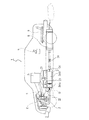
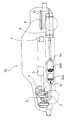
図1及び図2に、この実施の形態の排気ガス浄化システム1の構成を示す。この排気ガス浄化システム1では、ディーゼルエンジンEの排気マニホールドに接続する排気通路(排気管)2に連続再生型DPF3が設けられている。この連続再生型DPF3は、上流側に酸化触媒3Aaを下流側に触媒付きフィルタ3Abを有して構成される。
【0034】
この酸化触媒3Aaは、多孔質のセラミックのハニカム構造等の担持体に、白金(Pt)等の酸化触媒を担持させて形成され、触媒付きフィルタ3Abは、多孔質のセラミックのハニカムのチャンネルの入口と出口を交互に目封じしたモノリスハニカム型ウオールフロータイプのフィルタで形成される。このフィルタの部分に白金等の酸化触媒や酸化セリウム等のPM酸化触媒を担持する。この触媒付きフィルタ3Abでは、排気ガスG中のPM(粒子状物質)は多孔質のセラミックの壁で捕集(トラップ)される。
【0035】
この連続再生型DPF3の下流側の排気通路2に、排気絞りを行うための排気絞り弁(エキゾーストブレーキ)31が設けられる。そして、触媒付きフィルタ3AbのPMの堆積量を推定するために、連続再生型DPF3の前後に接続された導通管に差圧センサ21が設けられる。また、触媒付きフィルタ3Abの再生制御用に、酸化触媒3Aaの上流側に酸化触媒入口排気温度センサ(第1排気温度センサ)22が設けられ、また、酸化触媒3Aaの下流側で触媒付きフィルタ3Abの上流側にフィルタ入口排気温度センサ(第2排気温度センサ)23が設けられる。
【0036】
これらのセンサの出力値は、エンジンEの運転の全般的な制御を行うと共に、触媒付きフィルタ3Abの再生制御も行う制御装置(電子制御ボックス:ECU:エンジンコントロールユニット)5に入力され、この制御装置5から出力される制御信号により、エンジンEの燃料噴射弁15や、排気絞り弁31や、吸気通路6に設けられて吸気マニホールドへの吸気量を調整する吸気弁11等が制御される。
【0037】
この燃料噴射弁15は燃料ポンプ(図示しない)で昇圧された高圧の燃料を一時的に貯えるコモンレール(図示しない)に接続されており、制御装置5には、エンジンの運転のために、PTOのスイッチのON/OFF,ニュートラルスイッチのON/OFF,車両速度,冷却水温度,エンジン回転数,負荷(アクセル開度)等の情報も入力される。
【0038】
この構成では、吸入空気Aは、吸気通路6でターボチャージャ17のコンプレッサ17aとインタークーラ12を経由して、吸気弁11で、吸気量を調整された後、シリンダ13内の燃焼室14に入る。この燃焼室14には、燃料噴射弁15が設けられており、この燃料噴射弁15からの燃料噴射により、燃料と吸入空気Aとが混合し、ピストン18の圧縮により、自然発火して燃焼し、排気ガスGを発生する。この排気ガスGは、排気通路2のターボチャージャ17のタービン17bを経由して、連続再生型DPF3に入り浄化された排気ガスGcになって、排気絞り弁31を通過して消音器8を経由して大気中に放出される。
【0039】
次に、この排気ガス浄化システム1におけるDPFの再生制御について説明する。このDPFの再生制御は、図3に示すような制御系統により、図4及び図5に示すような制御フローに沿って行われる。この制御フローは、メインの制御フローから繰り返し呼ばれて実行される制御フローとして示してある。
【0040】
つまり、エンジンのスタートと共にエンジン全体を制御するメイン制御プログラムがスタートすると、このメイン制御プログラムから呼ばれて図4の制御フローがスタートし、制御フローを実行してメインの制御プログラムにリターンすると、再度メインの制御プログラムから呼ばれる。そして、メインの制御フローが終了するまで、この図4の制御フローが繰り返し実行される。
【0041】
そして、この図4の制御フローがスタートすると、ステップS11で、通常の運転制御を所定の時間(再生制御開始の判定を行う時間間隔に関係する時間)の間行う。この通常の運転制御では、再生のための強制的な燃料噴射等を行わずに、要求されるエンジン回転数及び負荷によって決まる燃料噴射、EGR制御、吸気絞り、排気絞り等に従ってエンジンを制御する。
【0042】
次のステップS12で、再生制御開始であるか否かの判定を行う。この判定は、差圧センサ21の差圧ΔPが所定の差圧判定値(DPF再生開始用)ΔP0を超えたか否かで判定する。この差圧判定値ΔP0は、触媒付きフィルタ3AbにおけるPMの蓄積量が限界になって再生が必要となる差圧を示すものである。
【0043】
このステップS12の再生制御開始の判定で、差圧ΔPが差圧判定値ΔP0を超えていない場合、即ち、再生制御開始でない場合には、ステップS11に戻り、通常の運転制御を行い、差圧ΔPが差圧判定値ΔP0を超えるまで、繰り返す。
【0044】
そして、ステップS12の再生制御開始の判定で、差圧ΔPが差圧判定値ΔP0を超えた場合には、ステップS20に行く。このステップS20では、酸化触媒3Aaの入口の排気温度T1のチェックを行い、排気温度T1が所定の第1判定温度Ta' より大きい場合には、ステップS30に行き、第1DPF再生制御を行う。この所定の第1判定温度Ta'は、酸化触媒3Aaの活性化に関係する温度であり、通常は酸化触媒3Aaの活性温度Taとされるが、別の温度、例えば、活性温度Taより少し高い温度(例えば210℃)等であってもよい。
【0045】
この第1DPF再生制御では排気絞り弁31は全開のままで、ポスト噴射を行う。このポスト噴射で排気通路2内にHC(燃料)を供給し、そのHCを酸化触媒3Aaで燃焼させることにより、触媒付きフィルタ3Abの入口の排気温度T2を蓄積されたPMの強制燃焼温度以上に上昇させてPMを強制燃焼して除去する。
【0046】
そして、このステップS30では、ステップS31の第1DPF再生制御を、所定の時間(再生制御終了の判定を行う時間間隔に関係する時間)の間行い、次のステップS32で、再生制御終了であるか否かの判定を行う。この判定は、差圧センサ21の差圧ΔPが所定の差圧判定値(PM再生終了用)ΔP1を超えたか否かで判定する。この差圧判定値ΔP1は、触媒付きフィルタ3AbにおけるPMの蓄積量が減少してPMの捕集を再開してもよい状態の差圧を示すものである。
【0047】
このステップS32で、再生制御終了でないと判定された場合には、ステップS20に戻り、ステップS31の第1DPF再生制御を繰り返しながら、PMの燃焼除去を行う。そして、ステップS32で、再生制御終了であると判定された場合には、リターンに行き、メイン制御フローに戻る。
【0048】
また、ステップS20の酸化触媒3Aaの入口の排気温度T1のチェックで、酸化触媒入口排気温度センサ22で検出された排気温度T1が所定の第1判定温度Ta’(ここでは210℃)未満である場合には、ステップS40からステップS50に行き、第2DPF再生制御を行う。ステップS40では、ステップS41の排気絞り弁併用の遅延多段噴射制御を所定の時間(排気温度T1の判定を行う時間間隔に関係する時間)の間行い、この制御を、次のステップS42の酸化触媒3Aaの入口の排気温度T1のチェックで、排気温度T1が第2判定温度Ta(活性温度、例えば200℃)以上になるまで行う。そして、第2判定温度Ta以上の場合には、ステップS50のフィルタ入口排気温度T2の調整制御に行き、PMの強制燃焼を行う。このステップS50では、図5に示す制御フローに従って、遅延多段噴射と共に排気絞り弁31の開閉制御を行う。
【0049】
つまり、ステップS40の排気絞り併用の遅延多段噴射で、排気温度T1を第2判定温度Ta以上に上昇させた後、ステップS50で排気絞り弁開度を調整して、排気温度T1を第2判定温度Ta以上に維持したまま、排気ガスを昇温させるのに必要なHCを酸化触媒3Aaに供給して、フィルタ入口排気温度T2がPM強制燃焼温度以上になるようにする。
【0050】
このステップS50では、ステップS51で触媒付きフィルタ3Abの入口の排気温度T2が所定の第3判定温度(PM強制燃焼下限温度、例えば500℃)Tb1未満であるか否かの判定を行う。この判定で、フィルタ入口排気温度センサ23で検出された排気温度T2が第3判定温度Tb1未満である場合には、ステップS52で排気絞り弁31を所定角度(Δα)の分だけ開いて(α=α+Δα)、所定の時間(排気温度T2の判定を行う時間間隔に関係する時間)の間、遅延多段噴射制御を行い、ステップS56に行く。また、排気温度T2が第3判定温度Tb1以上の場合には、ステップS53で排気温度T2が所定の第4判定温度(PM強制燃焼上限温度、例えば650℃)Tb2以上であるか否かの判定を行う。
【0051】
このステップS53で排気温度T2が第4判定温度Tb2未満である場合には、ステップS54で排気絞り弁31を所定角度(Δα)の分だけ閉じて(α=α−Δα)、所定の時間(排気温度T2の判定を行う時間間隔に関係する時間)の間、遅延多段噴射制御を行い、ステップS56に行く。また、排気温度T2が第4判定温度Tb2以上の場合には、ステップS55で排気絞り及び遅延多段噴射制御を解除し、ステップS56に行く。
【0052】
なお、この第3判定温度Tb1と第4判定温度Tb2は共に、触媒付きフィルタ3Abに蓄積されたPMの強制燃焼開始温度に関係する温度であり、触媒付きフィルタ3Abに担持された触媒の種類によって決まる温度であるが、第3判定温度Tb1は、触媒付きフィルタ3Abに蓄積されたPMが燃焼を開始するのに十分な温度の下限の排気温度とし、第4判定温度Tb2は、触媒付きフィルタ3Abに蓄積されたPMが暴走燃焼を開始するのを防止できる排気温度や、排気温度と燃料消費とPM燃焼除去の関係から効率よくPM燃焼除去できる上限の排気温度とする。
【0053】
ステップS56では再生制御終了であるか否かの判定を行う。この判定は、ステップS32の判定と同じである。このステップS56で再生制御終了でないと判定された場合には、ステップS51に戻り、ステップS51〜ステップS56を繰り返しながら排気温度T2がTb1≦T2<Tb2となるように制御しつつ、PMの燃焼除去を行う。そして、PMの燃焼除去が行われ、触媒付きフィルタ3Abの再生が十分でステップS56の判定で再生制御終了であると判定された場合にはリターンに行き、メイン制御フローに戻る。
【0054】
そして、メイン制御フローに戻ると、繰り返し図4の制御フローが呼ばれ、エンジンの停止まで、図4のスタートからリターンを繰り返す。
【0055】
次に、本発明の排気絞り併用の遅延多段噴射制御について説明する。以下の説明では、図6に示すような3段(パイロット噴射2回、主噴射1回)の多段噴射で説明するが、より多段噴射の方がよい。
【0056】
エンジンEの運転において、排気温度を上昇させるために、排気絞り弁31を閉弁する排気絞りをすることにより、エンジン出口排気マニホールド圧力が上昇する。この排圧上昇により、排気行程の排気ガス排出量が急激に減少し排気効率が激減する。
【0057】
次の吸気行程において、シリンダ13の燃焼室14内に残留する排気ガス量が極端に増加するが、噴射時期を遅延しているため、排気ガスの温度はある程度上昇しており、吸気行程では高温で大量の排気ガスが燃焼室14内に残留することになる。
【0058】
次の圧縮、燃焼行程では、燃焼室14内の温度は更に高温となる。そこに、多段噴射の最初の一段目の噴射をすると、極端な遅延噴射でも確実な着火が得られ、更に確実な燃焼に移行できる。そのため、極端な遅延噴射によって噴射量を増加しても、トルクに変換される燃焼エネルギーは極少量となり、低トルク変動で大きな初期燃焼が得られる。また、この一段目の噴射の増量された燃料の確実な燃焼によって燃焼室14内は膨張行程の中盤でも高温に保たれる。
【0059】
そこに、更に噴射量を増加して二段目の噴射を行うと、この噴射時期が低圧の膨張行程の後期であっても着火燃焼が生じ、発熱により排気ガスが昇温され更に燃焼室14内は高温となるが、この燃焼エネルギーはトルクの発生には寄与しない。
【0060】
次に、二段目の噴射燃料の燃焼が活発化している時期に三段目の噴射をする。この三段目の噴射(主噴射)では更に噴射量を増加してもトルクの発生に繋がらず、更に大きな火炎に増強できる。この排気弁開時期付近で燃焼した主噴射燃料は排気ガスの昇温に著しく大きな寄与をする。
【0061】
なお、エンジン回転数が800rpm付近の具体的な噴射例を例示すると、排気絞りによる排圧上昇は、例えば、排気温度を600℃以上にする場合はエンジン回転数が800rpm付近では、70kPa以上とし、最初の一段目噴射の時期は上死点後20°〜30°、最初の二段目噴射の時期は上死点後35°〜50°とし、この二段目噴射の噴射燃料量は一段目に対し3割から10割程度増量噴射する。
【0062】
次に、排気絞り弁31の段階的開閉制御によるフィルタ入口排気温度T2の調整制御について説明する。
【0063】
上記の排気絞り弁併用の遅延多段噴射により、高温で大量の排気ガスが燃焼行程の初期に残留し、遅延された噴射でも確実な着火燃焼が得られ排気温度が著しく上昇する。
【0064】
ここで、排気絞り弁31を開いていくと、排圧が減少するため燃焼室14内の高温の残留排気ガスが減少していくので、噴射燃料の着火燃焼能力が低下し、噴射された燃料の未燃焼分が増加するため、排気ガス中に燃料であるHCが増加していくことになる。この場合、排気ガス中へ流入するHCが増加する分、酸化触媒3Aaの入口の排気温度T1は低下する。しかし、酸化触媒3Aaに流入するHCの量は増加するので、排気温度T1が活性温度Ta以上であれば、HCが酸化触媒3Aaで燃焼するので、酸化触媒3Aaの後流のフィルタ入口排気温度T2は上昇する。
【0065】
逆に、排気絞り弁31を閉じていくと、排圧が増加するため燃焼室14内の高温の残留排気ガスが増加していくので、噴射燃料の着火燃焼能力が向上していき、噴射された燃料の未燃焼分が減少するため、排気ガス中に燃料であるHCが減少していくことになる。この場合、排気ガス中へ流入するHCが減少する分、酸化触媒3Aaの入口の排気温度T1は上昇する。しかし、酸化触媒3Aaに流入するHCの量は減少するので、排気温度T1が活性温度Ta以上であっても、酸化触媒3Aaで燃焼するHC量が減少するので、酸化触媒3Aaの後流のフィルタ入口排気温度T2は下降する。
【0066】
この機構を利用して酸化触媒3Aaの入口の排気温度T1と酸化触媒3Aaに供給するHC量を制御して、酸化触媒3AaにおけるHCの燃焼を制御し、酸化触媒3Aaの後流のフィルタ入口排気温度T2を制御することができる。
【0067】
なお、この排気絞り弁31の開度の調整は、段階的に行っても良く、連続的に行ってもよい。また、フィルタ入口の排気温度T2を目標値に一致させたり、目標範囲内に納めたりするフィードバック制御でもよいが、予め実験等からエンジンの回転数や負荷等に関する排気絞りの開度をマップデータ化しておき、このマップデータを参照して排気絞りの開度を決めるような制御であってもよい。
【0068】
図7に、実施例として、エンジン回転数が850rpmのアイドル運転時で排気絞り併用の過大遅延多段噴射を行い、PM強制再生のための排気絞り弁の段階的開閉制御による酸化触媒温度とフィルタ温度の変化を示す。
【0069】
この実施例では3段の多段噴射を採用しているが、排気絞りを行うと、排圧が上昇し、酸化触媒が排気絞り開始後1分程度で活性温度に到達している。しかし、排気絞りを行って排気絞り弁を閉じたままの場合には、HCの供給量が不足するため、フィルタ内温度はPMの強制燃焼温度まで上昇しないままとなっている。
【0070】
その後、排気絞りを解除して排気絞り弁の開度制御を行うと、排圧は急減しシリンダ内で燃焼する燃料の割合が低下して酸化触媒へのHCの供給量が増加するため、フィルタ入口温度は急上昇し、PM強制燃焼開始温度以上に上がる。一方、酸化触媒の入口の排気温度は下がる。
【0071】
従って、排気絞り弁の開度を調整することにより酸化触媒温度、酸化触媒入口排気温度及びフィルタ入口排気温度を制御できることが分かる。
【0072】
以上の構成の排気ガス浄化システム1によれば、差圧センサ21の差圧が上昇して設定量を超えて、連続再生型DPF装置3の触媒付きフィルタ3AbのPM蓄積量が再生が必要となった場合において、排気温度T1が第1判定温度Ta’(酸化触媒3Aaの活性温度Ta以上の温度)以上の場合には、排気絞り弁31を開いた第1DPF再生制御で触媒付きフィルタ3Abの再生を行うことができ、アイドル等の低負荷・低回転数のエンジン運転時のような排気温度が極めて低い温度である場合等の排気温度T1が第1判定温度Ta’より小さい場合には、第2DPF再生制御である排気絞り弁併用の遅延多段噴射制御と排気絞り弁の開閉制御による開度調整を行うフィルタ入口排気温度T2の調整制御により、触媒付きフィルタ3Abの再生を行うことができる。
【0073】
従って、アイドル運転等の低負荷・低回転時の排気温度が極めて低いエンジンの運転状態であっても、排気絞り併用の多段遅延噴射と共に排気絞りの開度調整を行うことにより、酸化触媒3Aaの入口の排気温度T1と触媒付きフィルタ3Abの入口温度T2を同時に調整でき、効率良く排気ガスを昇温して、PMを強制燃焼して除去し触媒付きフィルタ3Abを再生することができる。
【0074】
そのため,再生不能の運転状態の継続による触媒付きフィルタ3AbへのPMの過剰蓄積を回避でき、この過剰蓄積に起因するPMの暴走燃焼による触媒付きフィルタ3Abの溶損を防止できる。また、触媒付きフィルタ3Abの目詰まりによる排圧上昇を抑えることができるので、高排圧によるエンジンストール等の不具合の発生を回避でき、燃費も向上できる。
【0075】
更に、排気絞り併用の遅延多段噴射により、排気温度T1が酸化触媒3Aaの活性温度Ta以下の状態において排気ガス中に高濃度のHCが発生するのを回避できるので、酸化触媒3AaへのHCの蓄積を防止でき、酸化触媒3Aaに蓄積したHCの急激燃焼による高温発生を防止でき、この高温発生に起因する触媒の劣化や溶損を防止できる。
【0076】
その上、排気絞りを併用しない第1DPF再生制御と排気絞りを併用する遅延多段噴射の第2DPF再生制御とを排気温度T1によって使い分けているので、排圧の上昇期間を少なくでき、燃費の悪化等を防止できる。
【0077】
なお、上記では、触媒付きフィルタ3Abに酸化触媒とPM酸化触媒を担持させた連続再生型DPF3で説明したが、本発明は、フィルタに酸化触媒又はPM酸化触媒を担持させた連続再生型DPF、触媒を担持しないフィルタの連続再生型DPFに対しても適用可能である。
【0078】
【発明の効果】
以上に説明をしたように、本発明の排気ガス浄化システムによれば、従来技術では、排気温度が低くてフィルタに蓄積したPMの強制燃焼が行えなかったアイドルや低負荷域の運転状態においても、排気絞り併用の遅延多段噴射と排気絞りの開度調整による排気温度の調整により、噴射燃料の着火性及び燃焼性能の向上を図り、トルク変動の発生及び極端な白煙の発生を回避しながら、酸化触媒の上流側の排気温度のみならず、下流側の排気温度の変化に敏感に対応した排気ガス昇温制御を行うので、排気ガス昇温に必要な燃料も少ない量で、効率よく排気ガスを大幅に昇温でき、効率よくPMの再生燃焼を行うことができる。
【0079】
従って、DPF再生のための再生制御の際に、トルク変動が少なく、白煙の発生も防止できる連続再生型DPFを備えた排気ガス浄化システムとなる。
【図面の簡単な説明】
【図1】本発明に係る実施の形態の排気ガス浄化システムの構成図である。
【図2】本発明に係る実施の形態の排気ガス浄化システムのエンジン部分の構成を示す図である。
【図3】本発明に係る実施の形態の制御系統図である。
【図4】本発明に係る再生制御フローを示す図である。
【図5】図4の一部の制御フローを示す図である。
【図6】本発明に係る再生制御における多段噴射の一例を示す図である。
【図7】実施例の酸化触媒温度と排気ガスのフィルタ入口温度を示す図である。
【図8】従来技術の排気ガス浄化システムの一例を示すシステム構成図である。
【図9】従来技術の排気ガス浄化システムの他の一例を示すシステム構成図である。
【図10】従来技術の排気ガス浄化システムの他の一例を示すシステム構成図である。
【符号の説明】
1 排気ガス浄化システム
2 排気通路
3 連続再生型DPF
3Aa 酸化触媒
3Ab 触媒付きフィルタ
21 差圧センサ
22 酸化触媒入口排気温度センサ(第1排気温度センサ)
23 フィルタ入口排気温度センサ(第2排気温度センサ)
31 排気絞り弁
E ディーゼルエンジン
G 排気ガス
T1 酸化触媒の入口の排気温度
T2 フィルタの入口の排気温度
Ta’ 酸化触媒の活性温度以上の所定の温度(第1判定温度)
Ta 酸化触媒の活性温度(第2判定温度)
Tb1 PM再生燃焼下限温度(第3判定温度)
Tb2 PM再生燃焼上限温度(第4判定温度)
ΔP 差圧
ΔP0 差圧判定値(DPF再生開始用)
ΔP1 差圧判定値(DPF再生終了用)[0001]
BACKGROUND OF THE INVENTION
The present invention relates to an exhaust gas purification system that includes a continuously regenerating diesel particulate filter and purifies engine exhaust gas.
[0002]
[Prior art]
Emissions of particulate matter (PM: particulate matter: hereinafter referred to as PM) emitted from diesel engines have been strengthened year by year along with NOx, CO and HC. Improvement alone has made it impossible to respond. Therefore, a technology has been developed that collects PM discharged from the engine with a filter called a diesel particulate filter (DPF) and reduces the amount of PM discharged to the outside. Yes.
[0003]
The DPF that directly collects PM includes ceramic monolith honeycomb wall flow type filters and fiber type filters made of ceramic or metal fibers. Exhaust gas purification using these DPFs Similar to other exhaust gas purification systems, the system is installed in the middle of the exhaust passage of the engine and purifies exhaust gas generated by the engine.
[0004]
When the filter collects PM, the exhaust pressure rises in proportion to the amount collected, so it is necessary to regenerate the DPF by removing the collected PM by burning or the like. Various methods have been proposed for this regeneration method, including an electric heater heating type, a burner heating type, and a backwash type.
[0005]
However, when these regeneration methods are used, PM is burned by receiving energy supply from the outside, which leads to deterioration of fuel consumption, and control during regeneration is difficult, and PM collection, PM combustion (DPF) There is a problem that the system becomes large and complicated, such as requiring a two-system DPF system that alternately performs (regeneration).
[0006]
In order to solve this problem, a technique has been proposed in which the oxidation temperature of PM is lowered using an oxidation catalyst, and PM is oxidized by exhaust heat from the engine to regenerate DPF without receiving energy from the outside. In this case, since DPF regeneration is basically continuous, it is called a continuous regeneration type DPF system. However, these systems become a simpler one-system DPF system, and regeneration control is also simplified. There is an advantage that
[0007]
NO shown as an example in FIG. 2
[0008]
In FIG. 8, E is a diesel engine, 2 is an exhaust passage, 4 is a fuel pump system, 5 is an electronic control box, 7 is a battery, 8 is a silencer, and 9 is a fuel tank.
[0009]
Further, FIG. 9 shows NO in FIG. 2 An improved
[0010]
Then, in FIG. 10, a porous
[0011]
These DPF systems with a catalyst are composed of a catalyst and NO. 2 This is a system that realizes continuous regeneration of PM by lowering the PM oxidation start temperature than that of a normal filter by the oxidation reaction of PM.
[0012]
However, even if the PM oxidation start temperature is lowered, an exhaust temperature of about 350 ° C. is still necessary, so in low load operation and idle operation, the exhaust temperature is low, so PM oxidation and DPF self-regeneration occur. Absent. Therefore, if the engine operation state where the exhaust temperature is low, such as idling or low load, continues, PM will not be oxidized even if PM accumulates, resulting in increased exhaust pressure, worsening fuel consumption, and engine stop Troubles such as this may occur.
[0013]
Therefore, in these continuous regeneration type DPF systems, it is necessary to regenerate the DPF by calculating the PM accumulation amount in the filter from the engine operating conditions or estimating the PM accumulation amount from the filter pressure loss corresponding to the PM accumulation amount. When the conditions are set and this DPF regeneration requirement is satisfied, the exhaust gas temperature is forcibly raised, and the accumulated PM is forcibly burned and removed to perform DPF regeneration control.
[0014]
In the continuous regeneration type DPF system, in order to forcibly burn PM, an electronically controlled fuel injection system such as a common rail is used, and a multi-stage injection with a small injection amount performed before the main injection and an excessive amount of the main injection are performed. With delayed multistage injection with a combination of various delays, the exhaust temperature is raised above the activation temperature of the oxidation catalyst, then returned to normal injection control, and fuel (HC) such as light oil is exhausted by post injection or injection in the exhaust pipe, etc. This is added to the pipe, and this fuel is burned by the upstream oxidation catalyst, and the temperature of the exhaust gas flowing into the downstream filter is raised above the temperature at which the accumulated PM is forcibly burned. PM is forcibly burned and removed.
[0015]
In addition to increasing the temperature of the exhaust gas by multistage injection and using the exhaust throttle together, the exhaust pressure of the engine is increased to increase the amount of exhaust gas remaining in the intake stroke and to increase the temperature. There has also been proposed a method for increasing the exhaust temperature by improving the ignitability and combustion performance of the injected fuel by making it easier.
[0016]
As one of the methods, an exhaust throttle valve is provided on the downstream side of the trap filter (DPF) so that the exhaust temperature is maintained within a predetermined regeneration temperature range during filter regeneration, that is, the DPF inlet exhaust temperature is a predetermined temperature. An exhaust emission control device for a diesel engine that controls the valve opening degree of an exhaust throttle valve has been proposed (see, for example, Patent Document 1).
[0017]
[Patent Document 1]
Japanese Patent Laid-Open No. 04-81513
[0018]
[Problems to be solved by the invention]
However, in the conventional DPF regeneration control using multi-stage injection combined with the exhaust throttle, there is a problem that torque fluctuation in regeneration control operation becomes large and white smoke is generated.
[0019]
In other words, during regeneration control operation, after the exhaust temperature is raised above the activation temperature of the oxidation catalyst by multistage injection with exhaust throttle, the normal injection control is resumed. When returning to the injection control, torque fluctuation due to sudden change in exhaust pressure and torque fluctuation due to large change in injection timing occur. In addition, the exhaust temperature entering the oxidation catalyst may be reduced by normal injection, and it may be necessary to return from normal injection control to multistage injection combined with exhaust throttling. In this case, torque fluctuation also occurs.
[0020]
In addition, HC and white smoke may be generated due to a change in the injection amount at the time of switching from multistage injection with exhaust throttling to normal injection control.
[0021]
The present invention has been made to solve the above-described problems, and an object of the present invention is to provide an exhaust gas that has little torque fluctuation and can prevent generation of white smoke in a regeneration control operation for regeneration of a DPF in a continuous regeneration type DPF. It is to provide a gas purification system.
[0022]
[Means for Solving the Problems]
An exhaust gas purification system for achieving the above object includes a filter for collecting an oxidation catalyst and particulate matter from an upstream side in an exhaust passage of an internal combustion engine, and is located upstream of the oxidation catalyst or downstream of the filter. In the exhaust gas purification system in which an exhaust throttle valve is provided on the side, a first exhaust temperature sensor is disposed at the inlet of the oxidation catalyst, and a second exhaust temperature sensor is disposed between the oxidation catalyst and the filter, the regeneration of the DPF During the control, when the exhaust temperature detected by the first exhaust temperature sensor is equal to or lower than a predetermined first determination temperature, the exhaust throttle valve is closed. Including pilot injection Perform delayed multi-stage injection control and exhaust gas Until reaching the second judgment temperature as the activation temperature of the oxidation catalyst The temperature was raised and detected by the first exhaust temperature sensor When the exhaust temperature reaches the second determination temperature, Detected by the second exhaust temperature sensor When the exhaust temperature is equal to or lower than a predetermined third determination temperature, The exhaust throttle valve is stepwise or continuously Open and perform delayed multi-stage injection control Configured as follows.
[0023]
According to this configuration, in the regeneration control of the DPF, when the exhaust gas temperature at the inlet of the oxidation catalyst is lower than the first determination temperature such as the activation temperature of the oxidation catalyst, It is possible to significantly delay the misfire limit of the injection timing to be injected, increase the injection amount, create a large initial flame, improve the subsequent flame propagation power, and completely burn even a lean mixture As a result, generation of white smoke and misfire can be prevented, and the exhaust temperature can be significantly increased efficiently.
[0024]
Even when the exhaust temperature of the oxidation catalyst inlet becomes equal to or higher than the second determination temperature such as the activation temperature of the oxidation catalyst, the exhaust multi-stage injection combined with the exhaust throttle is continued without returning to the normal injection control. By adjusting the valve opening stepwise or continuously, the combustion state in the combustion chamber is controlled to adjust the supply amount of HC to be burned by the oxidation catalyst into the exhaust gas. Since the temperature is controlled, it is possible to avoid a sudden change in exhaust pressure, a sudden change in injection timing, and a rapid change in injection amount, and prevent fluctuations in output torque and generation of white smoke.
[0025]
In the exhaust gas purification system, after the exhaust temperature at the inlet of the oxidation catalyst has risen to the second determination temperature or higher, the exhaust temperature detected by the second exhaust temperature sensor exceeds the third determination temperature. In this case, the exhaust throttle valve is configured to be closed stepwise or continuously. In addition, after the exhaust temperature at the inlet of the oxidation catalyst has risen to the second determination temperature or higher, the exhaust temperature detected by the second exhaust temperature sensor is higher than a predetermined fourth determination temperature higher than the third determination temperature. In this case, the exhaust throttle valve and the delayed multi-stage injection control are canceled.
[0026]
With this configuration, it is possible to limit an increase in the exhaust temperature, so that runaway combustion of PM accumulated in the DPF can be avoided and fuel for increasing the exhaust temperature can be saved.
[0027]
In the exhaust gas purification system, when the exhaust temperature detected by the first exhaust temperature sensor is higher than a predetermined first determination temperature during the regeneration control of the DPF, a delay in opening the exhaust throttle valve is opened. Multi-stage injection control is performed, and the exhaust gas temperature is raised so that the exhaust temperature detected by the second exhaust temperature sensor is higher than the third determination temperature.
[0028]
According to this configuration, when there is a need for forced regeneration of the DPF, if the exhaust temperature in the operating state of the engine is higher than the predetermined first determination temperature, exhaust gas is not exhausted by delayed multistage injection without performing exhaust throttling. Since the temperature rises, the fuel consumption is remarkably reduced as compared with a system that performs exhaust throttling every time the DPF is forcedly regenerated, and the PM accumulated on the DPF can be efficiently burned and removed with low fuel consumption.
[0029]
Note that the first determination temperature and the second determination temperature are temperatures related to the exhaust temperature detected by the first exhaust temperature sensor and the activation temperature of the oxidation catalyst, and the actual oxidation is related to the measurement location and history. Strictly speaking, it is different from the activation temperature of the oxidation catalyst because it is different from the temperature of the catalyst, but it is preferable to set the first determination temperature slightly higher than the activation temperature of the oxidation catalyst for the sake of easy control. (2) The determination temperature is preferably the activation temperature of the oxidation catalyst.
[0030]
Further, the exhaust gas temperature detected by the second exhaust temperature sensor is also a temperature related to the activation temperature of the oxidation catalyst, and the third judgment temperature is the actual PM combustion start temperature based on the measurement location and history. Strictly speaking, it is different from the combustion start temperature of PM, but it is preferable to set the third determination temperature as the exhaust temperature at which the particulate matter accumulated in the filter starts combustion for the sake of simplicity of control.
[0031]
And the said filter is formed with the filter which carry | supported either an oxidation catalyst, PM oxidation catalyst, an oxidation catalyst, and PM oxidation catalyst. With this configuration, the exhaust temperature at which the particulate matter accumulated in the filter starts to combust can be lowered as compared with the case where the catalyst is not supported, so that fuel efficiency can be improved.
[0032]
DETAILED DESCRIPTION OF THE INVENTION
Hereinafter, an exhaust gas purification system according to an embodiment of the present invention is provided with a continuous regeneration type DPF (diesel particulate filter) configured by a combination of an oxidation catalyst (DOC) and a filter with catalyst (CSF). The system will be described as an example with reference to the drawings.
[0033]
1 and 2 show the configuration of the exhaust gas purification system 1 of this embodiment. In this exhaust gas purification system 1, a continuous
[0034]
The oxidation catalyst 3Aa is formed by supporting an oxidation catalyst such as platinum (Pt) on a carrier such as a porous ceramic honeycomb structure, and the catalyst-attached filter 3Ab is formed at the inlet of the channel of the porous ceramic honeycomb. And a monolith honeycomb wall flow type filter in which the outlets are alternately sealed. An oxidation catalyst such as platinum or a PM oxidation catalyst such as cerium oxide is supported on the filter portion. In this catalyst-attached filter 3Ab, PM (particulate matter) in the exhaust gas G is collected (trapped) by a porous ceramic wall.
[0035]
An exhaust throttle valve (exhaust brake) 31 for exhaust throttling is provided in the
[0036]
The output values of these sensors are input to a control device (electronic control box: ECU: engine control unit) 5 that performs overall control of the operation of the engine E and also performs regeneration control of the filter 3Ab with catalyst. The control signal output from the
[0037]
The
[0038]
In this configuration, the intake air A enters the
[0039]
Next, DPF regeneration control in the exhaust gas purification system 1 will be described. The regeneration control of the DPF is performed along a control flow as shown in FIGS. 4 and 5 by a control system as shown in FIG. This control flow is shown as a control flow that is repeatedly called from the main control flow and executed.
[0040]
That is, when the main control program for controlling the entire engine starts with the start of the engine, the control flow shown in FIG. 4 starts from this main control program. When the control flow is executed and returned to the main control program, the main control program is started again. Called from the main control program. Then, the control flow of FIG. 4 is repeatedly executed until the main control flow ends.
[0041]
Then, when the control flow of FIG. 4 starts, in step S11, normal operation control is performed for a predetermined time (time related to the time interval for determining whether to start regeneration control). In this normal operation control, the engine is controlled according to fuel injection, EGR control, intake throttle, exhaust throttle, etc. determined by the required engine speed and load without performing forced fuel injection for regeneration.
[0042]
In the next step S12, it is determined whether or not the reproduction control is started. This determination is made based on whether or not the differential pressure ΔP of the
[0043]
If the differential pressure ΔP does not exceed the differential pressure determination value ΔP0 in the determination of the regeneration control start in step S12, that is, if the regeneration control is not started, the process returns to step S11 to perform normal operation control, and the differential pressure The process is repeated until ΔP exceeds the differential pressure determination value ΔP0.
[0044]
If it is determined in step S12 that the regeneration control is started, if the differential pressure ΔP exceeds the differential pressure determination value ΔP0, the process proceeds to step S20. In this step S20, the exhaust temperature T1 at the inlet of the oxidation catalyst 3Aa is checked, and the exhaust temperature T1 is set to a predetermined value. When the temperature is higher than the first determination temperature Ta ′, Going to step S30, the first DPF regeneration control is performed. The predetermined first determination temperature Ta ′ is a temperature related to the activation of the oxidation catalyst 3Aa and is usually the activation temperature Ta of the oxidation catalyst 3Aa, but is slightly higher than another temperature, for example, the activation temperature Ta. It may be a temperature (for example, 210 ° C.).
[0045]
In the first DPF regeneration control, the post-injection is performed while the
[0046]
In step S30, the first DPF regeneration control in step S31 is performed for a predetermined time (a time related to the time interval for determining whether regeneration control is finished). In step S32, whether regeneration control is finished. Determine whether or not. This determination is made based on whether or not the differential pressure ΔP of the
[0047]
If it is determined in step S32 that the regeneration control has not ended, the process returns to step S20, and PM is burned and removed while repeating the first DPF regeneration control in step S31. If it is determined in step S32 that the regeneration control has ended, the process goes to return and returns to the main control flow.
[0048]
Further, the exhaust temperature T1 detected by the oxidation catalyst inlet
[0049]
That is, after the exhaust temperature T1 is raised to the second determination temperature Ta or higher in the delayed multistage injection combined with the exhaust throttle in step S40, the exhaust throttle valve opening is adjusted in step S50 to determine the exhaust temperature T1 in the second determination. While maintaining the temperature Ta or higher, HC required to raise the temperature of the exhaust gas is supplied to the oxidation catalyst 3Aa so that the filter inlet exhaust temperature T2 becomes equal to or higher than the PM forced combustion temperature.
[0050]
In step S50, it is determined in step S51 whether or not the exhaust temperature T2 at the inlet of the filter with catalyst 3Ab is lower than a predetermined third determination temperature (PM forced combustion lower limit temperature, for example, 500 ° C.) Tb1. In this determination, if the exhaust temperature T2 detected by the filter inlet
[0051]
If the exhaust temperature T2 is lower than the fourth determination temperature Tb2 in step S53, the
[0052]
The third determination temperature Tb1 and the fourth determination temperature Tb2 are both temperatures related to the forced combustion start temperature of PM accumulated in the filter with catalyst 3Ab, and depend on the type of catalyst supported on the filter with catalyst 3Ab. The third determination temperature Tb1 is the exhaust temperature that is the lower limit of the temperature sufficient for the PM accumulated in the catalyst-attached filter 3Ab to start combustion, and the fourth determination temperature Tb2 is the catalyst-determined filter 3Ab. The exhaust temperature at which PM accumulated in the engine can be prevented from starting runaway combustion, or the upper limit exhaust gas temperature at which PM combustion can be efficiently removed from the relationship between the exhaust temperature, fuel consumption, and PM combustion removal.
[0053]
In step S56, it is determined whether or not the reproduction control is finished. This determination is the same as the determination in step S32. If it is determined in step S56 that the regeneration control has not ended, the process returns to step S51, and the exhaust temperature T2 is controlled to satisfy Tb1 ≦ T2 <Tb2 while repeating steps S51 to S56, and PM is removed by combustion. I do. Then, PM is burned and removed, and when it is determined that the regeneration of the catalyst-attached filter 3Ab is sufficient and the regeneration control is completed in the determination of step S56, the process returns to the main control flow.
[0054]
When returning to the main control flow, the control flow of FIG. 4 is repeatedly called, and the return is repeated from the start of FIG. 4 until the engine is stopped.
[0055]
Next, the delayed multistage injection control using the exhaust throttle of the present invention will be described. In the following description, a multi-stage injection of three stages (two pilot injections and one main injection) as shown in FIG. 6 will be described, but multi-stage injection is better.
[0056]
In the operation of the engine E, in order to raise the exhaust temperature, the exhaust gas pressure of the engine outlet rises by performing the exhaust throttle that closes the
[0057]
In the next intake stroke, the amount of exhaust gas remaining in the
[0058]
In the next compression and combustion stroke, the temperature in the
[0059]
If the injection amount is further increased and second-stage injection is performed, ignition combustion occurs even when the injection timing is in the later stage of the low-pressure expansion stroke, and the exhaust gas is heated by heat generation, and the
[0060]
Next, the third-stage injection is performed at the time when the combustion of the second-stage injected fuel is active. In this third-stage injection (main injection), even if the injection amount is further increased, torque is not generated, and it can be increased to a larger flame. The main injection fuel combusted in the vicinity of the exhaust valve opening timing greatly contributes to the temperature rise of the exhaust gas.
[0061]
In addition, exemplifying a specific injection example where the engine speed is around 800 rpm, the exhaust pressure increase due to the exhaust throttle is, for example, 70 kPa or more when the engine speed is around 800 rpm when the exhaust temperature is set to 600 ° C. or more, The timing of the first stage injection is 20 ° to 30 ° after top dead center, and the timing of the
[0062]
Next, adjustment control of the filter inlet exhaust temperature T2 by the stepwise opening / closing control of the
[0063]
Due to the delayed multistage injection combined with the exhaust throttle valve described above, a large amount of exhaust gas remains at the beginning of the combustion stroke at a high temperature, and reliable ignition combustion is obtained even with delayed injection, and the exhaust temperature rises remarkably.
[0064]
Here, as the
[0065]
On the contrary, when the
[0066]
Using this mechanism, the exhaust temperature T1 at the inlet of the oxidation catalyst 3Aa and the amount of HC supplied to the oxidation catalyst 3Aa are controlled to control the combustion of HC in the oxidation catalyst 3Aa, and the filter inlet exhaust downstream of the oxidation catalyst 3Aa. The temperature T2 can be controlled.
[0067]
The adjustment of the opening degree of the
[0068]
FIG. 7 shows, as an example, an excessively delayed multistage injection combined with an exhaust throttle during idle operation at an engine speed of 850 rpm, and an oxidation catalyst temperature and a filter temperature by stepwise opening / closing control of an exhaust throttle valve for forced PM regeneration. Shows changes.
[0069]
In this embodiment, three-stage multistage injection is adopted. However, when exhaust throttling is performed, the exhaust pressure rises, and the oxidation catalyst reaches the activation temperature in about one minute after the start of exhaust throttling. However, when exhaust throttling is performed and the exhaust throttling valve is kept closed, the supply amount of HC is insufficient, so that the temperature in the filter does not rise to the forced combustion temperature of PM.
[0070]
After that, when the exhaust throttle is released and the opening control of the exhaust throttle valve is performed, the exhaust pressure decreases rapidly, the ratio of the fuel combusting in the cylinder decreases, and the amount of HC supplied to the oxidation catalyst increases. The inlet temperature rises rapidly and rises above the PM forced combustion start temperature. On the other hand, the exhaust temperature at the inlet of the oxidation catalyst decreases.
[0071]
Therefore, it can be seen that the oxidation catalyst temperature, the oxidation catalyst inlet exhaust temperature, and the filter inlet exhaust temperature can be controlled by adjusting the opening of the exhaust throttle valve.
[0072]
According to the exhaust gas purification system 1 having the above configuration, the differential pressure of the
[0073]
Therefore, even when the engine is in an operating state where the exhaust temperature is extremely low during low load and low rotation, such as idling, by adjusting the opening of the exhaust throttle together with the multistage delay injection combined with the exhaust throttle, the oxidation catalyst 3Aa The exhaust temperature T1 at the inlet and the inlet temperature T2 of the filter with catalyst 3Ab can be adjusted at the same time, and the exhaust gas can be efficiently heated to remove PM by forcibly burning and regenerating the filter with catalyst 3Ab.
[0074]
Therefore, excessive accumulation of PM in the filter with catalyst 3Ab due to continuation of the non-renewable operation state can be avoided, and melting of the filter with catalyst 3Ab due to runaway combustion of PM due to this excessive accumulation can be prevented. In addition, since an increase in exhaust pressure due to clogging of the filter with catalyst 3Ab can be suppressed, occurrence of problems such as engine stall due to high exhaust pressure can be avoided, and fuel consumption can be improved.
[0075]
Furthermore, the delayed multistage injection combined with the exhaust throttle can avoid the generation of high-concentration HC in the exhaust gas when the exhaust temperature T1 is equal to or lower than the activation temperature Ta of the oxidation catalyst 3Aa. Accumulation can be prevented, high temperature generation due to rapid combustion of HC accumulated in the oxidation catalyst 3Aa can be prevented, and deterioration or melting of the catalyst due to the high temperature generation can be prevented.
[0076]
In addition, since the first DPF regeneration control that does not use the exhaust throttle and the second DPF regeneration control that uses the delayed multistage injection that also uses the exhaust throttle are selectively used according to the exhaust temperature T1, the exhaust pressure increase period can be reduced, and the fuel consumption deteriorates. Can be prevented.
[0077]
In the above description, the continuous
[0078]
【The invention's effect】
As described above, according to the exhaust gas purification system of the present invention, even in the idling state where the exhaust temperature is low and the forced combustion of the PM accumulated in the filter could not be performed in the prior art, even in an operating state in a low load region. By adjusting the exhaust temperature by delay multistage injection combined with exhaust throttle and adjusting the opening of the exhaust throttle, the ignitability and combustion performance of the injected fuel is improved, while avoiding torque fluctuations and extreme white smoke The exhaust gas temperature rise control responds sensitively not only to the exhaust temperature upstream of the oxidation catalyst but also to the downstream exhaust temperature. The temperature of the gas can be greatly increased, and the regeneration combustion of PM can be performed efficiently.
[0079]
Therefore, in the regeneration control for regeneration of the DPF, the exhaust gas purification system including the continuous regeneration type DPF that can reduce the torque fluctuation and prevent the generation of white smoke.
[Brief description of the drawings]
FIG. 1 is a configuration diagram of an exhaust gas purification system according to an embodiment of the present invention.
FIG. 2 is a diagram showing a configuration of an engine portion of the exhaust gas purification system according to the embodiment of the present invention.
FIG. 3 is a control system diagram of the embodiment according to the present invention.
FIG. 4 is a diagram showing a regeneration control flow according to the present invention.
FIG. 5 is a diagram showing a part of the control flow of FIG. 4;
FIG. 6 is a diagram showing an example of multi-stage injection in regeneration control according to the present invention.
FIG. 7 is a graph showing an oxidation catalyst temperature and an exhaust gas filter inlet temperature in an example.
FIG. 8 is a system configuration diagram showing an example of a conventional exhaust gas purification system.
FIG. 9 is a system configuration diagram showing another example of a conventional exhaust gas purification system.
FIG. 10 is a system configuration diagram showing another example of a conventional exhaust gas purification system.
[Explanation of symbols]
1 Exhaust gas purification system
2 Exhaust passage
3 Continuous regeneration type DPF
3Aa oxidation catalyst
Filter with 3Ab catalyst
21 Differential pressure sensor
22 Oxidation catalyst inlet exhaust temperature sensor (first exhaust temperature sensor)
23 Filter inlet exhaust temperature sensor (second exhaust temperature sensor)
31 Exhaust throttle valve
E Diesel engine
G exhaust gas
Exhaust temperature at the inlet of T1 oxidation catalyst
Exhaust temperature at T2 filter inlet
Predetermined temperature above the activation temperature of the Ta ′ oxidation catalyst (first judgment temperature)
Ta oxidation catalyst activation temperature (second judgment temperature)
Tb1 PM regeneration combustion lower limit temperature (third judgment temperature)
Tb2 PM regeneration combustion upper limit temperature (fourth judgment temperature)
ΔP differential pressure
ΔP0 Differential pressure judgment value (for DPF regeneration start)
ΔP1 Differential pressure judgment value (for DPF regeneration end)
Claims (7)
前記DPFの再生制御の際に、前記第1排気温度センサで検出した排気温度が、所定の第1判定温度以下である時に、前記排気絞り弁を閉じてパイロット噴射を含む遅延多段噴射制御を行い、排気ガスを前記酸化触媒の活性温度とする第2判定温度になるまで昇温させると共に、
前記第1排気温度センサで検出した排気温度が前記第2判定温度になった場合、前記第2排気温度センサで検出した排気温度が所定の第3判定温度以下であるときに、前記排気絞り弁を段階的若しくは連続的に開いて遅延多段噴射制御を行うことを特徴とする排気ガス浄化システム。The exhaust passage of the internal combustion engine is provided with a filter for collecting the oxidation catalyst and particulate matter from the upstream side, an exhaust throttle valve is provided on the upstream side of the oxidation catalyst or on the downstream side of the filter, and the inlet of the oxidation catalyst is In an exhaust gas purification system in which one exhaust temperature sensor is provided with a second exhaust temperature sensor between the oxidation catalyst and the filter,
When the exhaust temperature detected by the first exhaust temperature sensor is equal to or lower than a predetermined first determination temperature during the regeneration control of the DPF, delayed multistage injection control including pilot injection is performed by closing the exhaust throttle valve. Elevating the exhaust gas until reaching a second determination temperature, which is the activation temperature of the oxidation catalyst ,
When the exhaust temperature detected by the first exhaust temperature sensor becomes the second determination temperature, the exhaust throttle valve when the exhaust temperature detected by the second exhaust temperature sensor is equal to or lower than a predetermined third determination temperature. An exhaust gas purification system that performs delayed multi-stage injection control by opening the valve stepwise or continuously.
Priority Applications (5)
| Application Number | Priority Date | Filing Date | Title |
|---|---|---|---|
| JP2003151113A JP4345359B2 (en) | 2003-05-28 | 2003-05-28 | Exhaust gas purification system |
| PCT/JP2004/007254 WO2004106703A1 (en) | 2003-05-28 | 2004-05-27 | Exhaust gas cleaning system |
| EP04745360A EP1627998B1 (en) | 2003-05-28 | 2004-05-27 | Exhaust gas cleaning system |
| CNB2004800147373A CN100427739C (en) | 2003-05-28 | 2004-05-27 | Exhaust gas cleaning system |
| US10/551,442 US7337608B2 (en) | 2003-05-28 | 2004-05-27 | Exhaust gas cleaning system |
Applications Claiming Priority (1)
| Application Number | Priority Date | Filing Date | Title |
|---|---|---|---|
| JP2003151113A JP4345359B2 (en) | 2003-05-28 | 2003-05-28 | Exhaust gas purification system |
Publications (2)
| Publication Number | Publication Date |
|---|---|
| JP2004353529A JP2004353529A (en) | 2004-12-16 |
| JP4345359B2 true JP4345359B2 (en) | 2009-10-14 |
Family
ID=33487209
Family Applications (1)
| Application Number | Title | Priority Date | Filing Date |
|---|---|---|---|
| JP2003151113A Expired - Fee Related JP4345359B2 (en) | 2003-05-28 | 2003-05-28 | Exhaust gas purification system |
Country Status (5)
| Country | Link |
|---|---|
| US (1) | US7337608B2 (en) |
| EP (1) | EP1627998B1 (en) |
| JP (1) | JP4345359B2 (en) |
| CN (1) | CN100427739C (en) |
| WO (1) | WO2004106703A1 (en) |
Families Citing this family (36)
| Publication number | Priority date | Publication date | Assignee | Title |
|---|---|---|---|---|
| AU2001244090A1 (en) * | 2000-03-21 | 2001-10-03 | Silentor Holding A/S | A silencer containing one or more porous bodies |
| JP4333289B2 (en) * | 2003-09-03 | 2009-09-16 | いすゞ自動車株式会社 | Exhaust gas purification system |
| JP4175281B2 (en) * | 2004-03-31 | 2008-11-05 | いすゞ自動車株式会社 | Exhaust gas purification system control method and exhaust gas purification system |
| FR2872202B1 (en) * | 2004-06-23 | 2006-11-03 | Peugeot Citroen Automobiles Sa | EMERGENCY MEANS REGENERATION SYSTEM FOR MOTOR VEHICLE ENGINE |
| JP4193801B2 (en) | 2005-01-13 | 2008-12-10 | トヨタ自動車株式会社 | Exhaust gas purification system for internal combustion engine |
| AT501336B1 (en) * | 2005-02-03 | 2007-02-15 | Avl List Gmbh | Assembly and series of steps to determine the operating efficiency of an automotive exhaust selective catalyst reduction unit |
| JP2006274907A (en) * | 2005-03-29 | 2006-10-12 | Mitsubishi Fuso Truck & Bus Corp | Exhaust emission control device |
| JP4665633B2 (en) * | 2005-07-12 | 2011-04-06 | 株式会社デンソー | Exhaust gas purification device for internal combustion engine |
| JP4779888B2 (en) * | 2005-11-07 | 2011-09-28 | 日産自動車株式会社 | Exhaust gas purification method and exhaust gas purification device |
| JP4017010B2 (en) | 2006-02-01 | 2007-12-05 | いすゞ自動車株式会社 | Exhaust gas purification system control method and exhaust gas purification system |
| GB0603898D0 (en) * | 2006-02-28 | 2006-04-05 | Johnson Matthey Plc | Exhaust system comprising catalysed soot filter |
| JP2007255304A (en) * | 2006-03-23 | 2007-10-04 | Mitsubishi Fuso Truck & Bus Corp | Exhaust emission control device |
| JP4049193B2 (en) | 2006-06-13 | 2008-02-20 | いすゞ自動車株式会社 | Exhaust gas purification system control method and exhaust gas purification system |
| JP4055808B2 (en) | 2006-06-13 | 2008-03-05 | いすゞ自動車株式会社 | Exhaust gas purification system control method and exhaust gas purification system |
| JP4862590B2 (en) * | 2006-09-28 | 2012-01-25 | トヨタ自動車株式会社 | Exhaust purification device |
| US20090044515A1 (en) * | 2007-08-14 | 2009-02-19 | Shuguang Lu | System and method for removing particulate matter from a diesel particulate filter |
| JP2009108775A (en) * | 2007-10-30 | 2009-05-21 | Toyota Motor Corp | Exhaust throttle valve opening control device for internal combustion engine |
| US8141348B2 (en) * | 2007-12-21 | 2012-03-27 | Detroit Diesel Corporation | Engine after-treatment controls using dosing below catalyst light-off temperature |
| EP2143918B1 (en) * | 2008-07-11 | 2014-10-22 | Perkins Engines Company Limited | After-treatment de-contamination system |
| US8631643B2 (en) * | 2009-12-22 | 2014-01-21 | Perkins Engines Company Limited | Regeneration assist delay period |
| US8615989B2 (en) * | 2010-01-25 | 2013-12-31 | Deere & Company | Method for regeneration of diesel particulate filter in an exhaust aftertreatment system of an IC engine |
| JP5440384B2 (en) * | 2010-05-25 | 2014-03-12 | いすゞ自動車株式会社 | Exhaust gas purification system |
| US8356476B2 (en) | 2010-08-09 | 2013-01-22 | Scott Gall | Diesel silencer capable of Tier 3 or Tier 4 operation |
| DE102011014718B4 (en) * | 2011-03-23 | 2012-11-22 | Umicore Ag & Co. Kg | Method of operating diesel engines to prevent white smoke formation during DPF regeneration |
| GB2491411B (en) * | 2011-06-03 | 2015-05-27 | Perkins Engines Co Ltd | Exhaust after treatment device mode regulation |
| JP5705676B2 (en) * | 2011-07-27 | 2015-04-22 | 株式会社日本自動車部品総合研究所 | Exhaust gas purification device for internal combustion engine |
| DE102011080963A1 (en) * | 2011-08-15 | 2013-02-21 | Robert Bosch Gmbh | Method for operating an internal combustion engine |
| US8756912B2 (en) * | 2012-03-16 | 2014-06-24 | GM Global Technology Operations LLC | Method of setting a particulate filter regeneration setpoint based on exhaust flow mass |
| DE102013207450A1 (en) * | 2013-04-24 | 2014-10-30 | Eberspächer Exhaust Technology GmbH & Co. KG | Exhaust system of an internal combustion engine |
| CN104454085B (en) * | 2014-10-29 | 2017-03-01 | 凯龙高科技股份有限公司 | A kind of combustion-supporting regeneration temperature control method of DPF diesel particulate filtration system oil spout |
| WO2017014772A1 (en) * | 2015-07-22 | 2017-01-26 | Cummins Inc. | System and method for controlling exhaust gas temperature |
| JP6565441B2 (en) * | 2015-07-31 | 2019-08-28 | いすゞ自動車株式会社 | Exhaust purification equipment |
| CN105736091B (en) * | 2016-03-15 | 2018-06-15 | 清华大学 | Diesel particulate trap method for controlling reproduction, apparatus and system stage by stage |
| JP7059147B2 (en) * | 2018-08-08 | 2022-04-25 | 三菱重工エンジン&ターボチャージャ株式会社 | Control device, exhaust gas purification system and control method |
| JP7178219B2 (en) * | 2018-09-10 | 2022-11-25 | 三菱重工エンジン&ターボチャージャ株式会社 | Control device, exhaust gas purification system, and engine control method |
| JP7257759B2 (en) | 2018-09-10 | 2023-04-14 | 三菱重工エンジン&ターボチャージャ株式会社 | Control device, engine and engine control method |
Family Cites Families (9)
| Publication number | Priority date | Publication date | Assignee | Title |
|---|---|---|---|---|
| JP2001115822A (en) * | 1999-10-19 | 2001-04-24 | Hino Motors Ltd | Particulate filter regenerating device for diesel engine |
| FR2816357B1 (en) * | 2000-11-03 | 2003-02-07 | Peugeot Citroen Automobiles Sa | ASSISTANCE SYSTEM FOR THE REGENERATION OF A PARTICLE FILTER INTEGRATED IN AN EXHAUST SYSTEM OF A VEHICLE DIESEL ENGINE |
| EP1363009B1 (en) * | 2001-02-20 | 2006-06-07 | Isuzu Motors Limited | Fuel injection control method for diesel engine and regenerative control method for exhaust gas after treatment device |
| JP2002242732A (en) * | 2001-02-20 | 2002-08-28 | Nissan Motor Co Ltd | Exhaust emission control device for internal combustion engine |
| JP2003083030A (en) * | 2001-09-07 | 2003-03-19 | Mitsubishi Motors Corp | Exhaust emission control device of engine |
| JP3599012B2 (en) * | 2001-10-01 | 2004-12-08 | トヨタ自動車株式会社 | Exhaust gas purification device for internal combustion engine |
| JP3835241B2 (en) * | 2001-10-15 | 2006-10-18 | トヨタ自動車株式会社 | Exhaust gas purification device for internal combustion engine |
| JP4042399B2 (en) * | 2001-12-12 | 2008-02-06 | 三菱自動車工業株式会社 | Exhaust purification device |
| JP4333289B2 (en) * | 2003-09-03 | 2009-09-16 | いすゞ自動車株式会社 | Exhaust gas purification system |
-
2003
- 2003-05-28 JP JP2003151113A patent/JP4345359B2/en not_active Expired - Fee Related
-
2004
- 2004-05-27 WO PCT/JP2004/007254 patent/WO2004106703A1/en active Application Filing
- 2004-05-27 CN CNB2004800147373A patent/CN100427739C/en not_active Expired - Fee Related
- 2004-05-27 EP EP04745360A patent/EP1627998B1/en not_active Expired - Fee Related
- 2004-05-27 US US10/551,442 patent/US7337608B2/en active Active
Also Published As
| Publication number | Publication date |
|---|---|
| EP1627998B1 (en) | 2011-07-13 |
| WO2004106703A1 (en) | 2004-12-09 |
| CN100427739C (en) | 2008-10-22 |
| EP1627998A1 (en) | 2006-02-22 |
| US20060201144A1 (en) | 2006-09-14 |
| CN1795320A (en) | 2006-06-28 |
| EP1627998A4 (en) | 2010-08-04 |
| JP2004353529A (en) | 2004-12-16 |
| US7337608B2 (en) | 2008-03-04 |
Similar Documents
| Publication | Publication Date | Title |
|---|---|---|
| JP4345359B2 (en) | Exhaust gas purification system | |
| JP4333289B2 (en) | Exhaust gas purification system | |
| KR100504422B1 (en) | Exhaust emission control device for engine | |
| US20040144069A1 (en) | Exhaust gas purifying system | |
| JP3951899B2 (en) | Diesel engine exhaust purification system | |
| JP3992057B2 (en) | Exhaust gas purification system control method and exhaust gas purification system | |
| US7115237B2 (en) | Exhaust gas purifying method and exhaust gas purifying system | |
| CZ20024051A3 (en) | Device for purification of exhaust gas | |
| JP2007040221A (en) | Exhaust emission control device | |
| JP2010031833A (en) | Exhaust emission control device for diesel engine | |
| JP3572439B2 (en) | Diesel engine exhaust purification system | |
| JP7152988B2 (en) | diesel engine | |
| JP4292923B2 (en) | Exhaust gas purification method and exhaust gas purification system for internal combustion engine | |
| JP4107017B2 (en) | Engine control device | |
| JP4285162B2 (en) | Exhaust gas purification system | |
| JP2006274983A (en) | Exhaust emission control device | |
| KR20160050201A (en) | Apparatus and method for regenerating diesel particular matter filter | |
| JP2020204308A (en) | diesel engine | |
| JP7366877B2 (en) | diesel engine | |
| JP7372899B2 (en) | diesel engine | |
| JP7152989B2 (en) | diesel engine | |
| WO2020255537A1 (en) | Diesel engine | |
| JP2005155534A (en) | Exhaust gas temperature raising device of internal combustion engine | |
| JP4554894B2 (en) | Exhaust gas purification method and exhaust gas purification system | |
| JP2022090200A (en) | diesel engine |
Legal Events
| Date | Code | Title | Description |
|---|---|---|---|
| A621 | Written request for application examination |
Free format text: JAPANESE INTERMEDIATE CODE: A621 Effective date: 20060421 |
|
| A131 | Notification of reasons for refusal |
Free format text: JAPANESE INTERMEDIATE CODE: A131 Effective date: 20090303 |
|
| A521 | Request for written amendment filed |
Free format text: JAPANESE INTERMEDIATE CODE: A523 Effective date: 20090428 |
|
| TRDD | Decision of grant or rejection written | ||
| A01 | Written decision to grant a patent or to grant a registration (utility model) |
Free format text: JAPANESE INTERMEDIATE CODE: A01 Effective date: 20090623 |
|
| A01 | Written decision to grant a patent or to grant a registration (utility model) |
Free format text: JAPANESE INTERMEDIATE CODE: A01 |
|
| A61 | First payment of annual fees (during grant procedure) |
Free format text: JAPANESE INTERMEDIATE CODE: A61 Effective date: 20090706 |
|
| R150 | Certificate of patent or registration of utility model |
Ref document number: 4345359 Country of ref document: JP Free format text: JAPANESE INTERMEDIATE CODE: R150 Free format text: JAPANESE INTERMEDIATE CODE: R150 |
|
| FPAY | Renewal fee payment (event date is renewal date of database) |
Free format text: PAYMENT UNTIL: 20120724 Year of fee payment: 3 |
|
| FPAY | Renewal fee payment (event date is renewal date of database) |
Free format text: PAYMENT UNTIL: 20120724 Year of fee payment: 3 |
|
| FPAY | Renewal fee payment (event date is renewal date of database) |
Free format text: PAYMENT UNTIL: 20130724 Year of fee payment: 4 |
|
| LAPS | Cancellation because of no payment of annual fees |