JP5324900B2 - Lip cosmetic applicator - Google Patents

Lip cosmetic applicator Download PDF

Info

Publication number
JP5324900B2
JP5324900B2 JP2008312704A JP2008312704A JP5324900B2 JP 5324900 B2 JP5324900 B2 JP 5324900B2 JP 2008312704 A JP2008312704 A JP 2008312704A JP 2008312704 A JP2008312704 A JP 2008312704A JP 5324900 B2 JP5324900 B2 JP 5324900B2
Authority
JP
Japan
Prior art keywords
cosmetic
application
longitudinal direction
applicator
application part
Prior art date
Legal status (The legal status is an assumption and is not a legal conclusion. Google has not performed a legal analysis and makes no representation as to the accuracy of the status listed.)
Active
Application number
JP2008312704A
Other languages
Japanese (ja)
Other versions
JP2010131329A (en
JP2010131329A5 (en
Inventor
一之 上原
悠 齋藤
乾綱 栗田
Current Assignee (The listed assignees may be inaccurate. Google has not performed a legal analysis and makes no representation or warranty as to the accuracy of the list.)
Kao Corp
Original Assignee
Kao Corp
Priority date (The priority date is an assumption and is not a legal conclusion. Google has not performed a legal analysis and makes no representation as to the accuracy of the date listed.)
Filing date
Publication date
Application filed by Kao Corp filed Critical Kao Corp
Priority to JP2008312704A priority Critical patent/JP5324900B2/en
Publication of JP2010131329A publication Critical patent/JP2010131329A/en
Publication of JP2010131329A5 publication Critical patent/JP2010131329A5/ja
Application granted granted Critical
Publication of JP5324900B2 publication Critical patent/JP5324900B2/en
Active legal-status Critical Current
Anticipated expiration legal-status Critical

Links

Images

Description

本発明は、口紅やリップグロス等の口唇化粧料を口唇に塗布するために特に好適に用いられる塗布用具を備えた口唇化粧料塗布具に関する。   The present invention relates to a lip cosmetic applicator provided with an applicator used particularly suitably for applying a lip cosmetic such as lipstick or lip gloss to the lips.

口紅やリップグロス等の口唇化粧料を口唇に塗布するための塗布具として、支持軸の先端に塗布部を備えた構造のものが一般に利用されている。塗布部は、植毛(フロック)を有するタイプと、植毛無し(スパチュラ)タイプのものに大別される。   As an applicator for applying lip cosmetics such as lipstick and lip gloss to the lips, a structure having an application portion at the tip of a support shaft is generally used. The application part is roughly classified into a type having flocking (flock) and a type having no flocking (spatula).

例えば特許文献1には、植毛(フロック)を有するタイプの塗布部が記載されている。この種の塗布部は、十分な量の化粧料を該塗布部に保持したい場合に採用されるものである。しかしながら、例えば口紅の上にグロスを重ね塗りする場合や、下地化粧料の上に口紅を重ね塗りする場合等のように、化粧料を重ね塗りする場合には、後から塗る化粧料の塗布操作を行うときに、先に塗られていた化粧料がフロックによって拭い取られてしまい、先に塗られていた化粧料の効果が減少してしまう。また、拭い取られた化粧料が塗布具に付着し、これが付着したまま塗布具を容器内に収容すると、化粧料どうしの混合が起こり、それによって化粧料の着色や変色等の不具合が生じることがある。   For example, Patent Document 1 describes a type of application unit having flocking. This type of application part is employed when it is desired to hold a sufficient amount of cosmetic in the application part. However, when applying cosmetics repeatedly, such as when applying gloss over lipstick or when applying lipstick over base cosmetics, the cosmetic application operation is applied later. When performing, the cosmetics previously applied are wiped off by the flock, and the effect of the cosmetics previously applied is reduced. In addition, if the wiped cosmetic material adheres to the applicator and the applicator is accommodated in the container while it is adhered, mixing of the cosmetics occurs, thereby causing problems such as coloring or discoloration of the cosmetic material. There is.

一方、特許文献2には植毛無し(スパチュラ)タイプの塗布部が記載されている。この塗布部はフロックを有していないので、上述の重ね塗りをする場合に、フロックによって先に塗られていた化粧料が拭い取られることはない。しかし、塗布部に角部を有していることに起因して、図19に示すように、該角部Cによって、先に塗られていた化粧料が削り取られてしまう。したがって、この塗布部も、上述した特許文献1に記載の塗布部と同様の不具合を起こすことがある。   On the other hand, Patent Document 2 describes a non-planted (spatula) type application unit. Since this application part does not have a flock, when the above-described overcoating is performed, the cosmetic previously applied by the flock is not wiped off. However, due to the application portion having a corner portion, as shown in FIG. 19, the previously applied cosmetic is scraped off by the corner portion C. Therefore, this application part may cause the same problem as the application part described in Patent Document 1 described above.

特開2004−587号公報JP 2004-587 A 特開2008−12177号公報JP 2008-12177 A

したがって本発明の目的は、上述した従来技術が有する種々の不都合を解消し得る口唇化粧料塗布具を提供することにある。   Accordingly, an object of the present invention is to provide a lip cosmetic applicator that can eliminate the various disadvantages of the prior art described above.

本発明は、化粧料を口唇に塗布するための塗布用具と、該化粧料を収容するための容器とを備え、該塗布用具が該容器の口部から該容器内に出入自在な口唇化粧料塗布具であって、
前記塗布用具は、前記化粧料を付着させるための塗布部と、先端に該塗布部を連結した支持軸を有しており、
前記塗布部は、中央部に窪み部が形成された凹面を一表面に有する扁平体からなる基体部を備え、該基体部はその表面全域が曲面のみで形成された平滑なものであり、
前記塗布用具が前記容器内に挿入された状態において、前記塗布部の凹面が該容器の底部方向を向くように、該塗布部が該支持軸の軸方向に対して傾斜している口唇化粧料塗布具を提供するものである。
The present invention comprises an application tool for applying cosmetics to the lips and a container for containing the cosmetics, and the application tool allows the application tools to enter and exit from the mouth of the container. An applicator,
The application tool has an application part for attaching the cosmetic, and a support shaft that connects the application part to the tip.
The application part includes a base part made of a flat body having a concave surface with a concave part formed in the center part on one surface, and the base part is a smooth one whose entire surface is formed only by a curved surface,
Lip cosmetic in which the application part is inclined with respect to the axial direction of the support shaft so that the concave surface of the application part faces the bottom part of the container in a state where the application tool is inserted into the container. An applicator is provided.

また本発明は、化粧料を口唇に塗布するための塗布用具と、該化粧料を収容するための容器とを備え、該塗布用具が該容器の口部から該容器内に出入自在な口唇化粧料塗布具であって、
前記塗布用具は、前記化粧料を付着させるための塗布部と、先端に該塗布部を連結した支持軸を有しており、
前記塗布部は、前記支持軸の延びる方向に長手方向を有し、該長手方向と直交する方向に幅方向を有する縦長の形状で、かつ該長手方向に沿って湾曲している基体部を備え、該基体部はその表面全域が曲面のみで形成された平滑なものであり、
長手方向に沿って湾曲した前記塗布部は、凹状に湾曲した側の面が、前記化粧料の付着面となっており、
前記付着面においては、その幅方向中央域に、長手方向に延び、かつ幅方向断面が略山形である凸条部が形成されており、略山形の該凸条部はその2つの斜面が、化粧料の保持が可能な凹状の湾曲面をなし、
前記塗布用具が前記容器内に挿入された状態において、前記塗布部の付着面が該容器の底部方向を向くように、該塗布部が該支持軸の軸方向に対して傾斜している口唇化粧料塗布具を提供するものである。
The present invention also includes an applicator for applying cosmetics to the lips and a container for containing the cosmetics, and the applicator can freely enter and exit the container from the mouth of the container. A material applicator,
The application tool has an application part for attaching the cosmetic, and a support shaft that connects the application part to the tip.
The application portion includes a base portion that has a longitudinal direction in a direction in which the support shaft extends, a longitudinal shape having a width direction in a direction orthogonal to the longitudinal direction, and is curved along the longitudinal direction. In addition, the base portion is a smooth surface formed entirely by a curved surface,
The application part that is curved along the longitudinal direction has a concave curved surface, which is an attachment surface of the cosmetic.
In the adhesion surface, in the central region in the width direction, a ridge portion extending in the longitudinal direction and having a substantially chevron-shaped cross section in the width direction is formed. Containing a concave curved surface that can hold cosmetics,
Lip makeup in which the applicator is inclined with respect to the axial direction of the support shaft so that the attachment surface of the applicator faces the bottom of the container when the applicator is inserted into the container A material applicator is provided.

本発明によれば、先に塗られていた化粧料を口唇表面から除去することなく、口唇に化粧料を首尾良く重ね塗りすることができる。   According to the present invention, the cosmetic can be successfully applied to the lips without removing the previously applied cosmetic from the lip surface.

以下、本発明の口唇化粧料塗布具を、その好ましい実施形態に基づき図面を参照しながら説明する。図1には、本発明の口唇化粧料塗布具の第1の実施形態の正面図が、一部破断した状態で示されている。   Hereinafter, the lip cosmetic applicator of the present invention will be described based on preferred embodiments with reference to the drawings. FIG. 1 shows a front view of a first embodiment of the lip cosmetic applicator of the present invention in a partially broken state.

図1に示すように、本実施形態の口唇化粧料塗布具1は、口唇化粧料4を口唇5に塗布するための塗布用具2と、口唇化粧料4を収容するための容器3とを備えている。以下、塗布用具2及び容器3についてそれぞれ説明する。   As shown in FIG. 1, the lip cosmetic applicator 1 of the present embodiment includes an application tool 2 for applying the lip cosmetic 4 to the lip 5 and a container 3 for containing the lip cosmetic 4. ing. Hereinafter, the application tool 2 and the container 3 will be described.

先ず、容器3について説明すると、容器3は有底の細長い円筒状のものである。容器3はその内部に液状化粧料4を収容できるようになっている。容器3は、その底部と対向して口部33を有する。口部33は上方に向けて開口している。口部33の外周面にはネジ部32が設けられている。このネジ部32は、後述する塗布用具2の蓋体23の内周面に設けられたネジ部(図示せず)と螺合可能になっている。   First, the container 3 will be described. The container 3 has a bottomed, elongated cylindrical shape. The container 3 can accommodate the liquid cosmetic 4 therein. The container 3 has a mouth 33 facing the bottom. The mouth portion 33 opens upward. A screw portion 32 is provided on the outer peripheral surface of the mouth portion 33. The screw portion 32 can be screwed with a screw portion (not shown) provided on the inner peripheral surface of the lid body 23 of the application tool 2 described later.

容器3における口部33はその近傍に弁部材31を有している。弁部材31は、容器3の口部33から底部に向けて縮径した漏斗状の形状をしており、その下端の位置に孔部31Aを有している。孔部31Aは、容器3の横断面視において、弁部材31の略中央部に形成されている。また孔部31Aは円孔となっている。しかし、孔部31Aの形状はこれに限られない。孔部31Aは、塗布用具2の先端に位置する塗布部21を容器3内に挿入し、また容器3内から抜き出すことが可能な大きさを有している。更に孔部31Aは、塗布部21を容器3内に挿入し、また容器3内から抜き出すときに、該塗布部21に接触する程度の大きさでもある。これによって、塗布用具2を抜き出すときに、先ず支持軸22に付着した化粧料4が弁部材31によって適度にしごき取られる。支持軸22に化粧料4が付着していると、塗布する必要のないところに間違えて化粧料を付着させてしまうおそれがあるので、これをしごき取ることで使い勝手が向上する。塗布用具2を更に抜き出すと、次に塗布部21に付着した化粧料4が弁部材31によって適度にしごき取られ、適量の化粧料4が塗布部21に保持される。この目的のために、弁部材31はゴム等の弾性材料から構成されている。なお図1においては、弁部材31は、口部33から若干離れた下方寄りに位置しているが、これに代えて、口部33の位置に弁部材31を配置してもよい。   The mouth 33 in the container 3 has a valve member 31 in the vicinity thereof. The valve member 31 has a funnel-like shape with a diameter reduced from the mouth 33 of the container 3 toward the bottom, and has a hole 31A at the lower end thereof. The hole portion 31 </ b> A is formed in a substantially central portion of the valve member 31 in the cross-sectional view of the container 3. The hole 31A is a circular hole. However, the shape of the hole 31A is not limited to this. The hole 31 </ b> A has such a size that the application part 21 positioned at the tip of the application tool 2 can be inserted into the container 3 and extracted from the container 3. Further, the hole portion 31A has a size enough to contact the application portion 21 when the application portion 21 is inserted into the container 3 and removed from the container 3. As a result, when the application tool 2 is extracted, the cosmetic material 4 adhering to the support shaft 22 is scraped off by the valve member 31 in an appropriate manner. If the cosmetic material 4 is attached to the support shaft 22, there is a risk that the cosmetic material may be mistakenly attached to a place that does not need to be applied. When the applicator 2 is further extracted, the cosmetic 4 adhering to the application part 21 is then appropriately scraped off by the valve member 31, and an appropriate amount of the cosmetic 4 is held in the application part 21. For this purpose, the valve member 31 is made of an elastic material such as rubber. In FIG. 1, the valve member 31 is positioned slightly downward from the mouth 33, but the valve member 31 may be disposed at the position of the mouth 33 instead.

容器3に収容される化粧料4としては、流動性を有する口唇化粧料が用いられる。そのような化粧料は、当該技術分野においてよく知られたものである。その例としては、下地塗り用化粧料、各種口紅、リップグロスやリップカラー等と称される仕上げ用のつや出し化粧料等が挙げられる。   As the cosmetic 4 accommodated in the container 3, a lip cosmetic having fluidity is used. Such cosmetics are well known in the art. Examples thereof include undercoat cosmetics, various lipsticks, finished glossy cosmetics called lip gloss and lip color, and the like.

容器3と組み合わせて用いられる塗布用具2は、塗布部21と支持軸22とを有している。これらの部材は、容器3の口部33から該容器3内に出入自在となっている。塗布部21は化粧料4を口唇に塗布するために用いられる。支持軸22は、その先端において塗布部21と連結している。塗布部21と支持軸22とは同一材料から一体的に構成されていてもよく、あるいは予め製造された2つの部材を所定の手段によって結合させて構成されていてもよい。   The application tool 2 used in combination with the container 3 has an application part 21 and a support shaft 22. These members can freely enter and leave the container 3 through the mouth 33 of the container 3. The application unit 21 is used to apply the cosmetic 4 to the lips. The support shaft 22 is connected to the application unit 21 at the tip thereof. The application part 21 and the support shaft 22 may be integrally configured from the same material, or may be configured by joining two members manufactured in advance by a predetermined means.

塗布用具2は、更に蓋体23を有している。蓋体23は、支持軸22の後端と連結している。蓋体23は、上述のとおり、その内周面にネジ部(図示せず)を有している。このネジ部は、上述した容器3のネジ部32と螺合可能になっている。蓋体23が容器3のネジ部32と螺合した状態においては、塗布具1は略円柱状の形状となる。この状態においては、塗布部21は容器3の底部よりも若干上方に位置している。   The application tool 2 further has a lid 23. The lid body 23 is connected to the rear end of the support shaft 22. As described above, the lid body 23 has a screw portion (not shown) on its inner peripheral surface. This screw portion can be screwed with the screw portion 32 of the container 3 described above. In a state where the lid body 23 is screwed with the screw portion 32 of the container 3, the applicator 1 has a substantially cylindrical shape. In this state, the application unit 21 is located slightly above the bottom of the container 3.

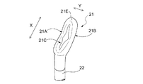
図2には塗布部21の拡大図が示されている。なお、図1と図2では、塗布部21の上下関係が逆転している。同図に示すように、塗布部21は扁平体からなる基体部を有している。後述する図18に示す第6の実施形態と異なり、本実施形態においては、基体部そのものが塗布部21となっている(図18に示す実施形態においては、基体部と植毛部とが塗布部21となっている)。塗布部21は、支持軸の延びる方向に長手方向Xを有し、長手方向Xと直交する方向に幅方向Yを有する縦長の形状である。更に塗布部21は、長手方向Xに沿って湾曲している。   FIG. 2 shows an enlarged view of the application unit 21. In FIG. 1 and FIG. 2, the vertical relationship of the application part 21 is reversed. As shown in the figure, the application part 21 has a base part made of a flat body. Unlike the sixth embodiment shown in FIG. 18 to be described later, in this embodiment, the base portion itself is the application portion 21 (in the embodiment shown in FIG. 18, the base portion and the flocking portion are the application portions. 21). The application unit 21 has a longitudinal shape having a longitudinal direction X in the direction in which the support shaft extends and a width direction Y in a direction orthogonal to the longitudinal direction X. Furthermore, the application part 21 is curved along the longitudinal direction X.

縦長の扁平形状からなる塗布部21は、第1の面21Aとこれに対向する第2の面21Bとを有する。第1の面21Aは凹面になっている。この凹面は、湾曲した塗布部21における凹状に湾曲した側の面である。一方、第2の面21Bは凸面になっている。この凸面は、湾曲した塗布部21における凸状に湾曲した側の面である。   The application part 21 which consists of a vertically long flat shape has the 1st surface 21A and the 2nd surface 21B which opposes this. The first surface 21A is concave. This concave surface is a surface of the curved application part 21 on the side curved in a concave shape. On the other hand, the second surface 21B is a convex surface. This convex surface is a surface of the curved application part 21 on the side curved in a convex shape.

塗布部21は、凹面である第1の面21Aの中央部に窪み部21Cを有している。窪み部21Cは化粧料4を保持する部位である。窪み部21Cは、塗布部21の長手方向に延びる略長円形をしている。塗布具1の使用時には、図3に示すように、化粧料4は窪み部21Cに保持される。   The application part 21 has a recessed part 21C at the center part of the first surface 21A which is a concave surface. The recessed portion 21 </ b> C is a portion that holds the cosmetic 4. The hollow portion 21 </ b> C has a substantially oval shape extending in the longitudinal direction of the application portion 21. When the applicator 1 is used, the cosmetic 4 is held in the recess 21C as shown in FIG.

塗布部21は、支持軸22に対して所定の角度をもって傾斜している。詳細には、塗布部21は、塗布用具2が容器3内に挿入された状態において、塗布部21の凹面である第1の面21Aが容器Aの底部方向を向くように、支持軸22の軸方向に対して傾斜している。塗布部21と支持軸22とがこのような傾斜関係で結合していることによって、塗布用具2を用いた化粧料4の塗布を容易に行うことができる(このことについては、後ほど詳述する)。   The application unit 21 is inclined at a predetermined angle with respect to the support shaft 22. Specifically, the application unit 21 is configured so that the first surface 21 </ b> A, which is a concave surface of the application unit 21, faces the bottom of the container A in a state where the application tool 2 is inserted into the container 3. It is inclined with respect to the axial direction. By applying the application part 21 and the support shaft 22 in such an inclined relationship, it is possible to easily apply the cosmetic 4 using the application tool 2 (this will be described in detail later). ).

図4(a)ないし(c)には、図2に示す塗布部21の正面図並びにその縦断面図及び横断面図が示されている。これらの図及び先に説明した図2から明らかなように、塗布部21は、その露出面の全域が曲面のみで形成されている。換言すれば、塗布部21は、角部を全く有していない滑らかなものである。図4(c)は塗布部21の長手方向と直交する方向での断面図であり、同図に示される第1の面21A側における二つの凸部211はその曲率半径が0.5mm以上で、かつ塗布部21の全幅長さの20%以下の寸法であることが好ましい。この範囲であれば下地を削り取らずに化粧料4を塗布することができ、かつ凸部211と凸部211の間に、十分な量の化粧料4を保持することが可能な凹部を形成することができる。また二つの凸部211の間に位置する窪み部21Cはその曲率半径が0.5mm以上で、かつ塗布部21の全幅長さの40%以下の寸法であることが好ましい。この範囲であれば、化粧料4を塗布したときに窪み部21Cから化粧料4が効果的に放出され、窪み部21Cに化粧料4が残ることがない。このような凸部211及び窪み部21Cの断面の曲線形状は、塗布部21の根元付近から先端付近までにわたって適用されていることが好ましい。図4(c)に示す塗布部21の断面の外周形状は、完全に曲線であることを要せず、微視的に細分化された多角形である場合や、一部が概略直線になっている場合等、実質的に曲線とみなせる場合も包含する。その場合は円弧曲線で近似して曲率半径を当てはめることができる。   4A to 4C show a front view, a longitudinal sectional view, and a transverse sectional view of the application unit 21 shown in FIG. As is clear from these drawings and FIG. 2 described above, the entire area of the exposed surface of the coating portion 21 is formed only by a curved surface. In other words, the application part 21 is smooth without any corners. FIG. 4C is a cross-sectional view in a direction perpendicular to the longitudinal direction of the application portion 21, and the two convex portions 211 on the first surface 21 </ b> A side shown in the same drawing have a radius of curvature of 0.5 mm or more. And it is preferable that it is a dimension of 20% or less of the full width length of the application part 21. FIG. Within this range, the cosmetic 4 can be applied without scraping the foundation, and a concave portion capable of holding a sufficient amount of the cosmetic 4 is formed between the convex portion 211 and the convex portion 211. be able to. Moreover, it is preferable that 21 C of hollow parts located between the two convex parts 211 are the dimension whose curvature radius is 0.5 mm or more and 40% or less of the full width length of the application part 21. FIG. Within this range, when the cosmetic 4 is applied, the cosmetic 4 is effectively released from the recess 21C, and the cosmetic 4 does not remain in the recess 21C. It is preferable that the curved shape of the cross section of the convex part 211 and the hollow part 21C is applied from the vicinity of the base of the application part 21 to the vicinity of the tip. The outer peripheral shape of the cross section of the application portion 21 shown in FIG. 4C does not need to be completely curved, and may be a polygon that is microscopically subdivided or a part thereof is a substantially straight line. The case where it can be substantially regarded as a curve is also included. In that case, the curvature radius can be applied by approximating with a circular arc curve.

更に塗布部21は、その露出面の全域が平滑になっている。換言すれば、塗布部21には、植毛加工等が施されておらず、かつ皺状、シボ状、梨地状等を始めとする各種の微細な凹凸を、その露出面の全域において全く有していない。要するに、塗布部21は「滑らか」で「つるつる」したものである。塗布部21がこのような特異な形状を有していることによって、本実施形態の塗布部具1を用いて化粧料を口唇に塗る場合、先に塗られている化粧料を拭い取ったり削り取ったりすることなく、その上に別の化粧料を首尾良く塗り重ねることができる。また、使用後においては、塗布部21に残存した化粧料を容易に除去することができるので、容器3内に塗布部21を挿入した場合に、容器3内に収容されている化粧料の着色や変色を効果的に防止することができる。   Furthermore, the entire area of the exposed surface of the application part 21 is smooth. In other words, the application portion 21 is not subjected to flocking processing and has various fine irregularities such as a ridge shape, a grain shape, a satin shape, and the like over the entire exposed surface. Not. In short, the application part 21 is “smooth” and “smooth”. Since the application part 21 has such a unique shape, when applying cosmetics to the lips using the application part 1 of the present embodiment, the cosmetics previously applied are wiped off or scraped off. It is possible to successfully apply another cosmetic material on it without having to. In addition, since the cosmetic remaining in the application part 21 can be easily removed after use, when the application part 21 is inserted into the container 3, the cosmetic contained in the container 3 is colored. And discoloration can be effectively prevented.

図5には、本実施形態の塗布具1の使用状態の一例が示されている。塗布用具2を容器3から抜き出すと、その間に、塗布部21に付着した化粧料4のうち、過剰量が弁部材31によってしごき落とされ、先に説明した図3に示すように、適量の化粧料4が塗布部21の窪み部21Cに保持された状態となる。この状態の塗布部21は、化粧料4が保持されていることが使用者に対して一目瞭然となるので、初めて使う者でも、塗りたいポイントに必要な量だけ化粧料4を塗ることが簡単かつ確実にできる。この場合、塗布部21の色を、化粧料4の色に対してコントラストの高い色とすれば、化粧料4が保持されていることが一層明瞭となる。そして、図5に示すように、塗布部21における化粧料4の保持面である第1の面21Aを上唇5A又は下唇5Bに対向させて、化粧料4の塗布を行う。この場合、先に述べたとおり、塗布部21は支持軸22の軸線に対して傾斜しているので、上唇5A及び下唇5Bのどちらに化粧料4を塗布する場合であっても、塗布用具2を把持する使用者の手の位置が、使用者の顔から離れるので、自然な状態で塗布の動作を行うことができる。   FIG. 5 shows an example of the usage state of the applicator 1 of the present embodiment. When the applicator 2 is extracted from the container 3, the excess amount of the cosmetic 4 adhering to the applicator 21 is rubbed off by the valve member 31, and an appropriate amount of makeup is applied as shown in FIG. 3 described above. The material 4 is held in the hollow portion 21 </ b> C of the application portion 21. The application unit 21 in this state makes it clear to the user that the cosmetic 4 is held, so even a first-time user can easily apply the cosmetic 4 in an amount necessary for the point to be applied. You can be sure. In this case, if the color of the application part 21 is a color having a high contrast with the color of the cosmetic 4, it becomes clearer that the cosmetic 4 is held. Then, as shown in FIG. 5, the cosmetic 4 is applied with the first surface 21 </ b> A that is the holding surface of the cosmetic 4 in the application unit 21 facing the upper lip 5 </ b> A or the lower lip 5 </ b> B. In this case, since the application part 21 is inclined with respect to the axis of the support shaft 22 as described above, the application tool can be applied to the upper lip 5A or the lower lip 5B. Since the position of the user's hand holding 2 is separated from the user's face, the application operation can be performed in a natural state.

塗布部21と支持軸22とがなす角度は10°〜50°が好ましい。この範囲であれば、塗布用具2を把持する使用者の手の位置が使用者の顔と接触する可能性が低くなり、かつ塗布用具2の容器3からの抜き挿しがし易くなり、しかも容器直径も小さく携帯性にも優れたものとすることができる。更に好ましい角度は20°〜40°である。   As for the angle which the application part 21 and the support shaft 22 make, 10 degrees-50 degrees are preferable. Within this range, the position of the user's hand holding the applicator 2 is less likely to come into contact with the user's face, and the applicator 2 can be easily inserted and removed from the container 3. Small diameter and excellent portability can be achieved. A more preferable angle is 20 ° to 40 °.

第1の面21Aの凹面は、塗布部21の側面視での曲率半径が概略で10mm〜100mm程度が好ましい。この範囲であれば、図5に示すように化粧料4を唇に塗布するとき、塗布面が唇に均一に接触するので、塗布面の縦方向にわたってほぼ全域で化粧料4を塗布することができる。   The concave surface of the first surface 21 </ b> A preferably has a curvature radius of approximately 10 mm to 100 mm in a side view of the application portion 21. Within this range, as shown in FIG. 5, when the cosmetic 4 is applied to the lips, the application surface uniformly contacts the lips, so that the cosmetic 4 can be applied almost throughout the longitudinal direction of the application surface. it can.

このようにして化粧料4を口唇に塗布すると、塗布された化粧料4は、図6に示すように、口唇の横方向にわたって頂上部Tの位置に特に多量に塗布される。この位置に化粧料4が多量に塗布された口唇は魅力的な外観を呈する。特に頂上部Tは曲率が大きく光を反射しやすい部位なので、当該部位にパール粉等の光輝性粉体が含まれている化粧料4が多量に塗布されると、光輝性粉体による反射が一層強調されて、一層魅力的な外観を呈する。口唇の頂上部Tに化粧料4が多量に塗布される理由は、凹面である第1の面21Aに、化粧料4を保持するための窪み部21Cが形成されているからである。窪み部21Cが形成されていない場合には、口唇の全体にわたって化粧料4が塗布される分だけ、頂上部Tに塗布される化粧料4の量が相対的に減少してしまう。   When the cosmetic 4 is applied to the lips in this way, the applied cosmetic 4 is applied in a particularly large amount at the position of the apex T along the lateral direction of the lips, as shown in FIG. The lips having a large amount of the cosmetic 4 applied at this position have an attractive appearance. In particular, the apex T has a large curvature and easily reflects light. Therefore, when a large amount of cosmetic 4 containing brilliant powder such as pearl powder is applied to the part, reflection by the brilliant powder is caused. It is more emphasized and has a more attractive appearance. The reason why the cosmetic 4 is applied in a large amount on the top T of the lip is that the concave portion 21C for holding the cosmetic 4 is formed on the concave first surface 21A. When the hollow portion 21C is not formed, the amount of the cosmetic 4 applied to the apex T is relatively reduced by the amount of the cosmetic 4 applied over the entire lip.

また、窪み部21Cが凹面である第1の面21Aに形成されていることによって、該窪み部21Cに保持されている化粧料4をすべて口唇に塗布することができる。この凹面は口唇にぴったりとフィットするからである。   Moreover, since the hollow part 21C is formed on the first surface 21A which is a concave surface, the cosmetic 4 held in the hollow part 21C can be applied to the lips. This is because the concave surface fits closely to the lips.

本実施形態の塗布具1における塗布部21は、先に述べたとおり、縦長の形状をしている。そして、その左右の側縁が、長手方向Xの少なくとも中央域において略直線状をなしかつ互いに平行になっている。つまり、塗布部21は、その長手方向Xに沿って、幅方向断面での形状変化が少なくなっている。塗布部21がこのような形状となっていることによって、塗布部21に付着した過剰の化粧料4を、弁部材31を用いてしごき落とす場合に、適量の化粧料4を塗布部21に保持させることができるという有利な効果が奏される。   The application part 21 in the applicator 1 of this embodiment has a vertically long shape as described above. The left and right side edges are substantially linear in at least the central region in the longitudinal direction X and are parallel to each other. That is, the application portion 21 has less shape change in the cross section in the width direction along the longitudinal direction X. Since the application part 21 has such a shape, when the excessive cosmetic 4 adhering to the application part 21 is rubbed off using the valve member 31, an appropriate amount of the cosmetic 4 is held in the application part 21. The advantageous effect that it can be made is produced.

左右の側縁が略直線状をなしていることと関連して、塗布部21は、これ幅方向Yで断面視したとき(図4(c)参照)、第2の面21Bが凸面となっている。このことによっても、過剰の化粧料4が塗布部21に付着しづらくなり、適量の化粧料4を塗布部21に保持させることができるという有利な効果が奏される。更に、凸面となっている第2の面21Bの該凸面の曲率が、弁部材31に設けられている円孔の孔部31Aの曲率と略一致していると、弁部材31による化粧料4のしごき取りが効率的に行われ、過剰の化粧料が塗布部21に付着しづらくなる。   In connection with the fact that the left and right side edges are substantially linear, when the application unit 21 is viewed in cross-section in the width direction Y (see FIG. 4C), the second surface 21B becomes a convex surface. ing. Also by this, the excessive cosmetic 4 becomes difficult to adhere to the application part 21, and the advantageous effect that an appropriate amount of cosmetics 4 can be hold | maintained at the application part 21 is show | played. Furthermore, if the curvature of the convex surface of the second surface 21B which is a convex surface substantially matches the curvature of the hole portion 31A of the circular hole provided in the valve member 31, the cosmetic 4 produced by the valve member 31 is used. The ironing is efficiently performed, and it is difficult for excessive cosmetics to adhere to the application part 21.

更に塗布部21は、図2に示すように、その先端部21Eが丸みを帯びた曲面になっているところ、該先端部21Eは、長手方向Xに沿う幅方向断面での形状変化が大きくなっている。先端部21Eがこのような形状になっていることで、塗布部21を容器3内から抜き出すときに、化粧料4の液切れ性が良好になり、過剰の化粧料4が塗布部21に付着しづらくなる。   Further, as shown in FIG. 2, the application portion 21 has a rounded curved surface at the tip portion 21 </ b> E, and the tip portion 21 </ b> E has a large shape change in the cross section in the width direction along the longitudinal direction X. ing. Since the tip portion 21E has such a shape, when the application portion 21 is pulled out from the container 3, the liquid drainage of the cosmetic 4 becomes good, and the excessive cosmetic 4 adheres to the application portion 21. It becomes difficult.

塗布部21は一般に合成樹脂製のものである。この合成樹脂としては、例えばポリエチレン、ポリプロピレン、ポリエチレンテレフタレート、ポリスチレンなどの比較的硬質なプラスチックを用いることが、塗布の操作性の点から好ましい。ここで言う硬質とは、塗布具1を使用するときに塗布部21に加わる圧力によって塗布部21が変形しない程度に硬い性質を有していることを言う。また、塗布部21は、その使用時に若干撓む程度の柔軟性を有していても差し支えなく、例えばシリコンやウレタンなどの各種エラストマーを使用することができ、塗布時の感触の点からエラストマーを用いることが好ましい。 The application part 21 is generally made of synthetic resin. As this synthetic resin, it is preferable to use a relatively hard plastic such as polyethylene, polypropylene, polyethylene terephthalate, and polystyrene from the viewpoint of operability of coating. The term “hard” as used herein means that the applicator 21 has such a hard property that the applicator 21 is not deformed by the pressure applied to the applicator 21 when the applicator 1 is used. Also, the application part 21 may be flexible enough to bend slightly during its use, and for example, various elastomers such as silicon and urethane can be used. It is preferable to use it.

次に、本発明の塗布具の第2ないし第6の実施形態を、図7ないし図18を参照しながら説明する。これらの実施形態については、先に説明した第1の実施形態と異なる点について説明し、特に説明しない点については、第1の実施形態に関して詳述した説明が適宜適用される。また、図7ないし図18において、図1ないし図6と同じ部材には同じ符号を付してある。   Next, 2nd thru | or 6th embodiment of the applicator of this invention is described, referring FIG. 7 thru | or FIG. These embodiments will be described with respect to differences from the first embodiment described above, and the descriptions detailed with respect to the first embodiment will be appropriately applied to points that are not particularly described. 7 to 18, the same members as those in FIGS. 1 to 6 are denoted by the same reference numerals.

図7及び図8に示す第2の実施形態においては、塗布部21における第1の面21Aに形成された窪み部21Cの形状が、第1の実施形態と相違している。詳細には、本実施形態における窪み部21Cは、塗布部21の長手方向Xに沿って縦長の略十字形ないし略菱形をしている。したがって、本実施形態の塗布部21の窪み部21Cに化粧料4が保持された状態は図9に示すようになる。本実施形態によれば、第1の実施形態に比較して、保持状態での化粧料4の形状が特徴的なので、塗布部21に化粧料4が保持されていることが使用者に対してより一層一目瞭然となり、化粧料4の塗布に際して使用者が塗布面を一層間違いづらくなる。また、塗布面である第1の面21Aの中央部に化粧料4がより多く保持されるので、塗布したときに唇の頂上部Tにより多くの量の化粧料4が塗布され、より一層魅力的な外観を呈することが可能になる。   In the second embodiment shown in FIGS. 7 and 8, the shape of the recess 21 </ b> C formed on the first surface 21 </ b> A in the application part 21 is different from that of the first embodiment. Specifically, the hollow portion 21 </ b> C in the present embodiment has a vertically long substantially cross shape or a substantially rhombus shape along the longitudinal direction X of the application portion 21. Therefore, the state in which the cosmetic 4 is held in the hollow portion 21C of the application portion 21 of the present embodiment is as shown in FIG. According to this embodiment, since the shape of the cosmetic 4 in the holding state is characteristic as compared with the first embodiment, it is possible for the user that the cosmetic 4 is held in the application unit 21. It becomes more obvious at a glance, and the user is less likely to make a mistake in the application surface when applying the cosmetic 4. In addition, since a larger amount of the cosmetic 4 is held at the central portion of the first surface 21A, which is the application surface, a larger amount of the cosmetic 4 is applied to the top portion T of the lips when applied, making it even more attractive. It becomes possible to exhibit a typical appearance.

図10及び図11に示す第3の実施形態においては、これまでの実施形態と異なり、塗布部21が略円形の扁平体からなる。第1の面21Aに形成されている窪み部21Cも略円形になっている。本実施形態によれば、塗布部21が、塗布面である第1の面21Aに直交する中心軸周りに軸対象な形状となるので、化粧料4を唇に塗布するとき、唇の表面上で塗布部21をどの方向に滑らせても塗布状態が変化せず、塗布厚みを一定にすることができる。例えば、先ず唇に対して横(左右)方向に塗布部21を動かして唇全体に化粧料4を塗布し、その後、唇に対して縦(上下)方向に塗布部21を動かすなどして細かな部分の部分的な塗布状態を修正することができる。その際も化粧料4の塗布量が変わらず、しかも先に塗布した下地には影響を及ぼさないので、手早く簡単に修正することができる。また、唇表面で円を描くように塗布部21を回して化粧料4を塗布したり、あるいは支持軸22を横に持って軸方向に引く、又は押すなどして塗布したりすることができ、使用者の好みあるいは使い慣れた方法に応じて持ち方や塗布方向を自由に選ぶことができる。   In the third embodiment shown in FIGS. 10 and 11, unlike the previous embodiments, the application part 21 is formed of a substantially circular flat body. The hollow portion 21C formed on the first surface 21A is also substantially circular. According to the present embodiment, the application portion 21 has an axial shape around the central axis that is orthogonal to the first surface 21A that is the application surface, and therefore when the cosmetic 4 is applied to the lips, Thus, no matter which direction the application part 21 is slid, the application state does not change and the application thickness can be made constant. For example, the application unit 21 is first moved laterally (left and right) with respect to the lips to apply the cosmetic 4 to the entire lips, and then the application unit 21 is moved vertically (up and down) with respect to the lips. It is possible to correct the partial application state of the part. Also in this case, the amount of the cosmetic 4 applied does not change and does not affect the previously applied base, so that it can be quickly and easily corrected. Also, the cosmetic 4 can be applied by turning the application part 21 so as to draw a circle on the lip surface, or it can be applied by holding the support shaft 22 sideways and pulling or pushing in the axial direction. The holding method and the application direction can be freely selected according to the user's preference or a familiar method.

これまでに説明してきた実施形態においては、化粧料4を保持するための窪み部21Cが塗布部21に1箇所のみ形成されていたが、図12及び図13に示す第4の実施形態においては、塗布部21の複数箇所において化粧料4が保持される。塗布部21は、第1及び第2の実施形態と同様に、支持軸22の延びる方向に長手方向Xを有し、長手方向Xと直交する方向に幅方向Yを有する縦長の形状である。また塗布部21は、長手方向Xに沿って湾曲している。更に、塗布部21は、その露出表面全域が曲面のみで形成された平滑なものになっている。長手方向に沿って湾曲した塗布部21は、凹状に湾曲した側に第1の面21Aを有し、凸状に湾曲した側に第2の面21Bを有している。そして塗布部21は、塗布用具2が容器3内に挿入された状態において、第1の面21Aが容器3の底部方向を向くように、塗布部21が支持軸22の軸方向に対して傾斜している。   In the embodiment described so far, only one recess 21C for holding the cosmetic 4 is formed in the application part 21, but in the fourth embodiment shown in FIG. 12 and FIG. The cosmetic 4 is held at a plurality of locations of the application unit 21. Similar to the first and second embodiments, the application unit 21 has a longitudinal shape having a longitudinal direction X in the extending direction of the support shaft 22 and a width direction Y in a direction orthogonal to the longitudinal direction X. The application unit 21 is curved along the longitudinal direction X. Furthermore, the application part 21 has a smooth surface in which the entire exposed surface is formed only by a curved surface. The applicator 21 curved along the longitudinal direction has a first surface 21A on the concavely curved side and a second surface 21B on the convexly curved side. The application unit 21 is inclined with respect to the axial direction of the support shaft 22 so that the first surface 21A faces the bottom of the container 3 in a state where the application tool 2 is inserted into the container 3. doing.

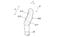
塗布部21においては、第1の面21Aが、化粧料4の付着面となっている。化粧料4の付着面である第1の面21Aにおいては、その幅方向Yの中央域に、長手方向Xに延び、かつ幅方向Yの断面が略山形である凸条部21Dが一条形成されている。凸条部21Dは、塗布部21の長手方向Xのほぼ全長にわたって形成されている。凸条部21Dはその高さが、その延びる方向にそってほぼ同じになっている。   In the application part 21, the first surface 21 </ b> A is an adhesion surface of the cosmetic 4. On the first surface 21 </ b> A, which is the attachment surface of the cosmetic 4, a single ridge portion 21 </ b> D extending in the longitudinal direction X and having a substantially chevron-shaped cross section in the width direction Y is formed in the central region in the width direction Y. ing. The protruding portion 21 </ b> D is formed over substantially the entire length in the longitudinal direction X of the application portion 21. The height of the protruding portion 21D is substantially the same along the extending direction.

略山形をなす凸条部21Dは、図13(c)に示すように、2つの斜面21F,21Fを有している。斜面21Fは、塗布部21の長手方向Xに沿って、該塗布部21のほぼ全長にわたって形成されている。斜面21Fは、化粧料4の保持が可能な凹状の湾曲面をなしている。そして、図14に示すように、この湾曲面に化粧料4が保持される。つまり同図に示すように、塗布部21には、その両側部の位置に、長手方向Xに延びる二条の化粧料保持領域が形成される。化粧料4の保持の程度は、凹状の湾曲の程度を調整することでコントロールできる。この場合、2つの湾曲面21F,21Fの湾曲の程度は同じでもよく、又は異なっていてもよい。   As shown in FIG. 13C, the convex strip portion 21D having a substantially mountain shape has two inclined surfaces 21F and 21F. The inclined surface 21 </ b> F is formed along the longitudinal direction X of the application part 21 over substantially the entire length of the application part 21. The inclined surface 21 </ b> F has a concave curved surface capable of holding the cosmetic 4. And as shown in FIG. 14, the cosmetics 4 are hold | maintained on this curved surface. That is, as shown in the figure, the application portion 21 has two cosmetic holding regions extending in the longitudinal direction X at positions on both sides thereof. The degree of holding the cosmetic 4 can be controlled by adjusting the degree of concave curvature. In this case, the degree of curvature of the two curved surfaces 21F and 21F may be the same or different.

このように本実施形態の塗布部21は、二条の化粧料保持領域を有しており、より多くの化粧料4を保持することができるので、化粧料4を保持した状態での1回当りの塗布可能面積が増える。その結果塗布部21に化粧料4を保持させるために塗布部21を容器3に戻して再び出す操作の回数を減らすことができる。また、二条の化粧料保持領域が使用者の目を引きやすいので、塗布部21に化粧料4が保持されていることが使用者に対してより一層一目瞭然となり、化粧料4の塗布に際して使用者が塗布面を一層間違いづらくなる。   Thus, since the application part 21 of this embodiment has two articles | goods cosmetics holding | maintenance area | regions and can hold | maintain more cosmetics 4, it is per time in the state holding the cosmetics 4 The area that can be applied increases. As a result, it is possible to reduce the number of operations for returning the application part 21 to the container 3 and returning it in order to hold the cosmetic 4 in the application part 21. Further, since the two cosmetic holding areas are easy to catch the eye of the user, it is more obvious to the user that the cosmetic 4 is held in the application portion 21, and the user can apply the cosmetic 4 when applying the cosmetic 4. However, it becomes harder to make a mistake on the coated surface.

図15及び16に示す第5の実施形態は、第4の実施形態の変形例である。本実施形態が第4の実施形態と相違する点は、凸条部21Dの形状である。詳細には、第4の実施形態における凸条部21Dはその高さが、その延びる方向にそってほぼ同じになっていたのに対し、本実施形態における凸条部21Dは、長手方向Xの中央域における高さが、長手方向Xの先端域及び後端域における高さよりも低くなっている。長手方向Xの中央域における凸条部21の高さは、該中央域に化粧料4を保持可能な程度に低いものである。要するに、凸状部21Dは、長手方向Xの中央域において化粧料4の付着が可能になっている。その結果、本実施形態の塗布部21においては、その両側部の位置に、長手方向Xに延びる二条の化粧料保持領域が形成され、かつ長手方向X及び幅方向Yの中央域にも化粧料保持領域が形成される。したがって、本実施形態の塗布部21に化粧料4を保持させると、図17に示すように、塗布部21の正面視において、略H字形の化粧料保持領域が形成される。   The fifth embodiment shown in FIGS. 15 and 16 is a modification of the fourth embodiment. The point that this embodiment is different from the fourth embodiment is the shape of the ridge portion 21D. In detail, the height of the convex portion 21D in the fourth embodiment is substantially the same along the extending direction, whereas the convex portion 21D in the present embodiment has a length in the longitudinal direction X. The height in the central area is lower than the height in the front end area and the rear end area in the longitudinal direction X. The height of the ridges 21 in the central region in the longitudinal direction X is low enough to hold the cosmetic 4 in the central region. In short, the convex portion 21 </ b> D allows the cosmetic 4 to adhere in the central region in the longitudinal direction X. As a result, in the application part 21 of the present embodiment, two cosmetic holding regions extending in the longitudinal direction X are formed at the positions on both sides, and the cosmetics are also formed in the central region in the longitudinal direction X and the width direction Y. A holding region is formed. Accordingly, when the cosmetic 4 is held by the application unit 21 of the present embodiment, a substantially H-shaped cosmetic holding region is formed in the front view of the application unit 21 as shown in FIG.

本実施形態によれば、二条の化粧料保持領域により化粧料の保持量が増加するので、化粧料4を保持した状態での1回当りの塗布可能面積が増え、塗布部21に化粧料4を保持させるために塗布部21を容器3に戻して再び出す操作の回数を減らすことができる。そのうえ、塗布部21の中央部により多くの化粧料4が保持されるので、塗布したときに唇の頂上部Tにより多くの化粧料4が塗布され、より一層魅力的な外観を呈することが可能になる。また、本実施形態の塗布部21は、略H字形という特徴的な形状なので、塗布部21に化粧料4が保持されていることが使用者に対してより一層一目瞭然となり、化粧料4の塗布に際して使用者が塗布面を一層間違いづらくなる。   According to the present embodiment, since the amount of cosmetics retained is increased by the two cosmetics retaining regions, the area that can be applied at one time in a state where the cosmetics 4 are retained increases, and the cosmetics 4 are applied to the application part 21. The number of operations for returning the applicator 21 to the container 3 and returning it again can be reduced. In addition, since a large amount of the cosmetic 4 is held in the central portion of the application part 21, a large amount of the cosmetic 4 is applied to the top portion T of the lips when applied, and a more attractive appearance can be obtained. become. Moreover, since the application part 21 of this embodiment is the characteristic shape of substantially H shape, it will become clear to a user that the cosmetics 4 are hold | maintained at the application part 21, and the application of cosmetics 4 will become clearer. At this time, the user is more likely to make a mistake in the application surface.

これまで説明してきた実施形態は、基体部そのものが塗布部21となっている実施形態であったが、図18に示す第6の実施形態においては、塗布部21が、扁平体からなる基体部と、該基体部の表面に植毛処理が施されてなる植毛部とから構成されている。なお、本実施形態は、先に説明した第1の実施形態の塗布用具における扁平な基体部の表面に植毛部を設けた実施形態であるが、同様の実施形態は、第2ないし第5の実施形態にも適用可能である。基体部の表面に植毛処理が施されることにより、表面が曲面で形成されかつ平滑であるという基体部の特徴を損なうことなく、化粧料の塗布時に塗布部21に保持可能な化粧料の量を、これまでに説明してきた実施形態よりも更に多くすることができる。その結果、化粧料の塗布回数を減らすことが可能となる。また、本実施形態は、以下に述べる理由(1)ないし(3)から、植毛繊維が下地化粧料を拭い取ってしまう不具合を最小限に抑えることが可能となる。   The embodiment described so far is an embodiment in which the base portion itself is the coating portion 21, but in the sixth embodiment shown in FIG. 18, the coating portion 21 is a base portion made of a flat body. And a flocked portion obtained by performing a flocking process on the surface of the base portion. In addition, although this embodiment is an embodiment in which a flocked portion is provided on the surface of the flat base portion in the applicator of the first embodiment described above, the same embodiment includes the second to fifth embodiments. The present invention can also be applied to the embodiment. The amount of the cosmetic that can be held in the application part 21 during the application of the cosmetic without impairing the characteristics of the base part that the surface is formed with a curved surface and is smooth by performing the flocking treatment on the surface of the base part. Can be increased more than the embodiments described so far. As a result, it is possible to reduce the number of times the cosmetic is applied. In addition, in the present embodiment, for the reasons (1) to (3) described below, it is possible to minimize the problem that the flocked fibers wipe off the base cosmetic.

(1)塗布部21が口唇にぴったりとフィットする凹面を形成しているので、塗布具の塗布面全体に均等に力が加わり、部分的に大きな力が加わって下地化粧料を拭い取ってしまうという不具合を低減できる。かつ、塗布面に窪み部を備えているので唇と接触する面積が小さくなり、下地化粧料を拭い取ってしまう量を最小限にできる。
(2)窪み部に化粧料4が保持されていることから、植毛繊維は化粧料4に埋もれており、植毛繊維と口唇表面の下地化粧料とが直に接触する面積を最小限にとどめることができるので、下地化粧料を拭い取ってしまう前に化粧料4を塗布することができる。保持されている化粧料4が放出尽くされた時には、既に口唇の下地化粧料の表面に化粧料が塗布された状態なので、植毛繊維が下地化粧料を拭い取る機会を低減することができる。
(3)化粧料は、過剰量が弁部材によってしごき落とされ化粧料4が塗布部21の窪み部21Cに保持された状態にあることから、塗布部21が使用者に対して一目瞭然となるので、使用者が塗布具の塗布面を正しく認識して使うことができ、間違えて化粧料がしごき落とされている面を使用して下地化粧料を拭い取ってしまう失敗を防ぐことができる。
(1) Since the application part 21 forms a concave surface that fits snugly on the lips, force is evenly applied to the entire application surface of the applicator, and a large force is partially applied to wipe off the base cosmetic. Can be reduced. And since the application part is provided with the hollow part, the area which contacts a lip becomes small and the quantity which wipes off base cosmetics can be minimized.
(2) Since the cosmetic 4 is held in the recess, the flocked fiber is buried in the cosmetic 4, and the area where the flocked fiber and the base cosmetic on the lip surface are in direct contact is minimized. Therefore, the cosmetic 4 can be applied before the base cosmetic is wiped off. When the retained cosmetic 4 is exhausted, the cosmetic has already been applied to the surface of the base cosmetic of the lips, so the chance that the flocked fibers wipe off the base cosmetic can be reduced.
(3) Since the cosmetic is excessively squeezed out by the valve member and the cosmetic 4 is held in the recess 21C of the application part 21, the application part 21 becomes obvious to the user. The user can correctly recognize and use the application surface of the applicator, and can prevent a mistake in wiping off the base cosmetic material by mistakenly using the surface on which the cosmetic material has been scraped off.

また植毛処理された塗布具の別の利点として、化粧料の塗布時にソフトな感覚を付与することができるという点も挙げられる。   Another advantage of the applicator that has undergone flocking treatment is that a soft sensation can be imparted when cosmetics are applied.

植毛部を構成する繊維は、長さが0.1〜3mmで、太さが0.5T(デシテックス)〜5Tのものが好ましい。長さ及び太さがこの範囲のなかで、異なる2種以上の繊維を組み合わせて用いることも可能である。繊維の材質は、塗布時に求められる感触に応じ、適切なものが選択される。一般にはポリアミド樹脂を用いることで、好ましいソフトな感触を得ることができる。基体部の表面に植毛処理を施すためには、静電植毛法等の公知の技術を適宜採用すればよい。   The fibers constituting the flocked part preferably have a length of 0.1 to 3 mm and a thickness of 0.5 T (decitex) to 5 T. It is also possible to use a combination of two or more different fibers within this range in length and thickness. As the material of the fiber, an appropriate material is selected according to the feel required at the time of application. In general, a preferable soft feel can be obtained by using a polyamide resin. In order to perform the flocking process on the surface of the base portion, a known technique such as an electrostatic flocking method may be appropriately employed.

以上、本発明をその好ましい実施形態に基づき説明したが、本発明は前記実施形態に制限されず、種々の変更が可能である。例えば図1ないし図11に示す実施形態における塗布部21の窪み部21Cの形状は、上述したものに限られず、種々の形状を採用することができる。   As mentioned above, although this invention was demonstrated based on the preferable embodiment, this invention is not restrict | limited to the said embodiment, A various change is possible. For example, the shape of the hollow portion 21C of the application portion 21 in the embodiment shown in FIGS. 1 to 11 is not limited to the above-described shape, and various shapes can be adopted.

図1は、本発明の口唇化粧料塗布具の第1の実施形態の容器を破断した状態で示す正面図である。FIG. 1 is a front view showing a state in which the container of the first embodiment of the lip cosmetic applicator of the present invention is broken. 図2は、図1に示す口唇化粧料塗布具における塗布部を拡大して示す斜視図である。FIG. 2 is an enlarged perspective view showing an application part in the lip cosmetic applicator shown in FIG. 図3は、図2に示す塗布部に化粧料を保持させた状態を示す斜視図である。FIG. 3 is a perspective view illustrating a state in which the cosmetic is held in the application unit illustrated in FIG. 2. 図4(a)は図1に示す口唇化粧料塗布具における塗布部の正面図であり、図4(b)は図4(a)におけるb−b線断面図であり、図4(c)は図4(b)におけるc−c線断面図である。4 (a) is a front view of the application part of the lip cosmetic applicator shown in FIG. 1, FIG. 4 (b) is a cross-sectional view taken along line bb in FIG. 4 (a), and FIG. 4 (c). FIG. 5 is a cross-sectional view taken along the line cc in FIG. 図5は、図1に示す口唇化粧料塗布具の使用状態の一例を示す説明図である。FIG. 5 is an explanatory diagram showing an example of a usage state of the lip cosmetic applicator shown in FIG. 1. 図6は、図1に示す口唇化粧料塗布具を用いて化粧料を口唇に塗った状態を模式的に示す図である。FIG. 6 is a diagram schematically showing a state in which cosmetics are applied to the lips using the lip cosmetic applicator shown in FIG. 1. 図7は、本発明の口唇化粧料塗布具の第2の実施形態における塗布部を示す斜視図(図2相当図)である。FIG. 7 is a perspective view (corresponding to FIG. 2) showing an application portion in the second embodiment of the lip cosmetic applicator of the present invention. 図8(a)は、図7に示す塗布部の側面図であり、図8(b)は図8(a)におけるb−b線断面図であり、図8(c)は図8(a)におけるc−c線断面図であり、図8(d)は図8(a)におけるd−d線断面図である。8A is a side view of the coating portion shown in FIG. 7, FIG. 8B is a cross-sectional view taken along line bb in FIG. 8A, and FIG. 8C is FIG. ) Is a cross-sectional view taken along the line cc in FIG. 8, and FIG. 8D is a cross-sectional view taken along the line dd in FIG. 8A. 図9は、図7に示す塗布部に化粧料を保持させた状態を示す斜視図である。FIG. 9 is a perspective view illustrating a state in which the cosmetic is held in the application unit illustrated in FIG. 7. 図10は、本発明の口唇化粧料塗布具の第3の実施形態における塗布部を示す斜視図(図2相当図)である。FIG. 10 is a perspective view (corresponding to FIG. 2) showing an application part in the third embodiment of the lip cosmetic applicator of the present invention. 図11(a)は、図10に示す塗布部の側面図であり、図11(b)は図11(a)におけるb−b線断面図である。Fig.11 (a) is a side view of the application part shown in FIG. 10, FIG.11 (b) is the bb sectional view taken on the line in Fig.11 (a). 図12は、本発明の口唇化粧料塗布具の第4の実施形態における塗布部を示す斜視図(図2相当図)である。FIG. 12 is a perspective view (corresponding to FIG. 2) showing an application part in the fourth embodiment of the lip cosmetic applicator of the present invention. 図13(a)は、図12に示す塗布部の側面図であり、図13(b)は図13(a)におけるb−b線断面図であり、図13(c)は図13(a)におけるc−c線断面図であり、図13(d)は図13(a)におけるd−d線断面図である。FIG. 13A is a side view of the application unit shown in FIG. 12, FIG. 13B is a cross-sectional view taken along line bb in FIG. 13A, and FIG. 13C is FIG. ) Is a cross-sectional view taken along a line cc in FIG. 13, and FIG. 13D is a cross-sectional view taken along a line dd in FIG. 13A. 図14は、図12に示す塗布部に化粧料を保持させた状態を示す斜視図である。FIG. 14 is a perspective view showing a state in which the cosmetic is held in the application section shown in FIG. 図15は、本発明の口唇化粧料塗布具の第5の実施形態における塗布部を示す斜視図(図2相当図)である。FIG. 15 is a perspective view (corresponding to FIG. 2) showing an application part in the fifth embodiment of the lip cosmetic applicator of the present invention. 図16(a)は、図15に示す塗布部の側面図であり、図16(b)は図16(a)におけるb−b線断面図であり、図16(c)は図16(a)におけるc−c線断面図であり、図16(d)は図16(a)におけるd−d線断面図であり、図16(e)は図16(a)におけるe−e線断面図であり、図16(f)は図16(a)におけるf−f線断面図である。16 (a) is a side view of the application section shown in FIG. 15, FIG. 16 (b) is a cross-sectional view taken along the line bb in FIG. 16 (a), and FIG. 16 (c) is FIG. FIG. 16D is a cross-sectional view taken along the line dd in FIG. 16A, and FIG. 16E is a cross-sectional view taken along the line ee in FIG. FIG. 16 (f) is a cross-sectional view taken along line ff in FIG. 16 (a). 図17は、図15に示す塗布部に化粧料を保持させた状態を示す斜視図である。FIG. 17 is a perspective view illustrating a state in which the cosmetic is held in the application unit illustrated in FIG. 15. 図18は、本発明の口唇化粧料塗布具の第6の実施形態における塗布部を示す斜視図(図2相当図)である。FIG. 18 is a perspective view (corresponding to FIG. 2) showing an application part in the sixth embodiment of the lip cosmetic applicator of the present invention. 図19は、従来技術の口唇化粧料塗布具において、化粧料塗布時に下地が削られる状態を模式的に示す図である。FIG. 19 is a diagram schematically showing a state in which the base is shaved during cosmetic application in a conventional lip cosmetic applicator.

符号の説明Explanation of symbols

1 口唇化粧料塗布具
2 塗布用具
21 塗布部
21A 第1の面(凹面)
21B 第2の面(凸面)
21C 窪み部
21D 凸条部
22 支持軸
23 蓋体
3 容器
31 弁部材
31A 孔部
33 口部
4 化粧料
DESCRIPTION OF SYMBOLS 1 Lip cosmetic application tool 2 Application tool 21 Application part 21A 1st surface (concave surface)
21B 2nd surface (convex surface)
21C hollow part 21D ridge part 22 support shaft 23 lid 3 container 31 valve member 31A hole part 33 mouth part 4 cosmetics

Claims (5)

化粧料を口唇に塗布するための塗布用具と、該化粧料を収容するための容器とを備え、該塗布用具が該容器の口部から該容器内に出入自在な口唇化粧料塗布具であって、
前記塗布用具は、前記化粧料を付着させるための塗布部と、先端に該塗布部を連結した支持軸を有しており、
前記塗布部は、前記支持軸の延びる方向に長手方向を有し、該長手方向と直交する方向に幅方向を有する縦長の形状で、かつ該長手方向に沿って湾曲している基体部を備え、該基体部はその表面全域が曲面のみで形成されており、
長手方向に沿って湾曲した前記塗布部は、凹状に湾曲した側の面が、前記化粧料の付着面となっており、
前記付着面においては、その幅方向中央域に、長手方向に延び、かつ幅方向断面が略山形である凸条部が形成されており、略山形の該凸条部はその2つの斜面が、化粧料の保持が可能な凹状の湾曲面をなし、
前記塗布用具が前記容器内に挿入された状態において、前記塗布部の付着面が該容器の底部方向を向くように、該塗布部が該支持軸の軸方向に対して傾斜している口唇化粧料塗布具。
An application tool for applying cosmetics to the lips and a container for containing the cosmetics, wherein the application tool is a lip cosmetic application tool that can enter and exit from the mouth of the container. And
The application tool has an application part for attaching the cosmetic, and a support shaft that connects the application part to the tip.
The application portion includes a base portion that has a longitudinal direction in a direction in which the support shaft extends, a longitudinal shape having a width direction in a direction orthogonal to the longitudinal direction, and is curved along the longitudinal direction. In addition, the entire surface of the base portion is formed only by a curved surface,
The application part that is curved along the longitudinal direction has a concave curved surface, which is an attachment surface of the cosmetic.
In the adhesion surface, in the central region in the width direction, a ridge portion extending in the longitudinal direction and having a substantially chevron-shaped cross section in the width direction is formed. Containing a concave curved surface that can hold cosmetics,
Lip makeup in which the applicator is inclined with respect to the axial direction of the support shaft so that the attachment surface of the applicator faces the bottom of the container when the applicator is inserted into the container Material applicator.
前記塗布部に形成された長手方向に延びる前記凸条部は、該長手方向の中央域における高さが、該長手方向の先端域及び後端域における高さよりも低く、それによって、該中央域においても化粧料の付着が可能になっている請求項1に記載の口唇化粧料塗布具。 The protruding portion formed in the coating portion and extending in the longitudinal direction has a height in a central region in the longitudinal direction lower than a height in a front end region and a rear end region in the longitudinal direction, thereby the central region. The lip cosmetic applicator according to claim 1, wherein the cosmetic can also be attached to the lip. 前記塗布部は、その長手方向に延びる左右の側縁が、該長手方向の少なくとも中央域において略直線状をなしかつ互いに平行になっており、
前記容器の口部又はその近傍に、前記塗布部と接触しながら該塗布部の挿入・抜き出しが可能な孔部を略中央部に有する弁部材が設けられている請求項又は2に記載の口唇化粧料塗布具。
The application part, the left and right side edges extending in the longitudinal direction are substantially linear and parallel to each other at least in the central region of the longitudinal direction,
The mouth or in the vicinity of the container, according to claim 1 or 2 the valve member is provided with a substantially central portion inserted and withdrawn capable hole of the coating cloth part while in contact with the coating unit Lip cosmetic application tool.
前記孔部は円孔からなり、
前記塗布部は、前記付着面と対向する面が凸面になっており、
前記塗布部の幅方向での断面視における前記凸面の曲率が、前記円孔の曲率と略一致している請求項3に記載の口唇化粧料塗布具。
The hole is a circular hole,
The application part has a convex surface facing the adhesion surface,
The lip cosmetic applicator according to claim 3 , wherein a curvature of the convex surface in a cross-sectional view in the width direction of the application part substantially coincides with a curvature of the circular hole.
前記基体部の表面に植毛処理が施されている請求項1〜のいずれか一項に記載の口唇化粧料塗布具。 The lip cosmetic applicator according to any one of claims 1 to 4 , wherein the surface of the base portion is subjected to a flocking treatment.
JP2008312704A 2008-12-08 2008-12-08 Lip cosmetic applicator Active JP5324900B2 (en)

Priority Applications (1)

Application Number Priority Date Filing Date Title
JP2008312704A JP5324900B2 (en) 2008-12-08 2008-12-08 Lip cosmetic applicator

Applications Claiming Priority (1)

Application Number Priority Date Filing Date Title
JP2008312704A JP5324900B2 (en) 2008-12-08 2008-12-08 Lip cosmetic applicator

Related Child Applications (2)

Application Number Title Priority Date Filing Date
JP2013130995A Division JP5716056B2 (en) 2013-06-21 2013-06-21 Lip cosmetic applicator
JP2013130994A Division JP5718983B2 (en) 2013-06-21 2013-06-21 Lip cosmetic applicator

Publications (3)

Publication Number Publication Date
JP2010131329A JP2010131329A (en) 2010-06-17
JP2010131329A5 JP2010131329A5 (en) 2011-11-04
JP5324900B2 true JP5324900B2 (en) 2013-10-23

Family

ID=42343267

Family Applications (1)

Application Number Title Priority Date Filing Date
JP2008312704A Active JP5324900B2 (en) 2008-12-08 2008-12-08 Lip cosmetic applicator

Country Status (1)

Country Link
JP (1) JP5324900B2 (en)

Families Citing this family (5)

* Cited by examiner, † Cited by third party
Publication number Priority date Publication date Assignee Title
EP2486821B1 (en) 2009-10-09 2017-12-13 Kao Corporation Lip cosmetic application device
FR2994068B1 (en) * 2012-08-01 2015-12-11 Oreal COSMETIC PRODUCT APPLICATOR, DEVICE AND ASSOCIATED METHOD
JP6263341B2 (en) * 2013-07-08 2018-01-17 大成化工株式会社 Application container and application member
KR102201522B1 (en) * 2017-12-18 2021-01-12 (주)아모레퍼시픽 Tip applicator and cosmetic application device including the same
JP7346258B2 (en) * 2019-11-15 2023-09-19 株式会社コーセー coating body

Family Cites Families (3)

* Cited by examiner, † Cited by third party
Publication number Priority date Publication date Assignee Title
FR2793663B1 (en) * 1999-05-19 2001-08-03 Oreal DEVICE FOR PACKAGING AND APPLYING A COSMETIC PRODUCT, PARTICULARLY FOR MAKING LIP
JP4257860B2 (en) * 2005-04-19 2009-04-22 中得工業株式会社 Cosmetic material applicator
FR2886112B1 (en) * 2005-05-24 2007-08-10 Oreal PACKAGING AND APPLICATION DEVICE

Also Published As

Publication number Publication date
JP2010131329A (en) 2010-06-17

Similar Documents

Publication Publication Date Title
EP2486821B1 (en) Lip cosmetic application device
JP5059350B2 (en) Container with cosmetic applicator
KR102313932B1 (en) Applicator for applying a cosmetic product
JP4286023B2 (en) Applicator having an applicator element configured to apply a substance to the skin
JP6063685B2 (en) Cosmetic applicator
JP5324900B2 (en) Lip cosmetic applicator
US20190000222A1 (en) Cosmetic product applicator tip, and related applicator and applicator assembly
JP6758394B2 (en) Applicator for applying eyeliner
JP5718983B2 (en) Lip cosmetic applicator
JP5716056B2 (en) Lip cosmetic applicator
JP2007236977A (en) Applicator comprising sloping applicator element
US7487784B2 (en) Applicator including a stem connected to a handle member via a hinge
CN108430258A (en) Eye cosmetic applies deposite device and eye toiletry
JP3977336B2 (en) Improved coated product package and manufacturing method
JP5822222B2 (en) Liquid applicator
JP4984040B2 (en) Liquid cosmetic container
JP2018110638A (en) Cosmetic applicator
JP2004008801A (en) Applicator with hinge and applying method of cosmetics
JP7346258B2 (en) coating body
US11963600B2 (en) Cosmetic container having wiper capable of removing cosmetic liquid from application support rod having non-circular cross-sectional area
CN110049696B (en) Applicator for a cosmetic product and associated applicator assembly
JP2015208636A (en) Lip cosmetic application device
JP2022131377A (en) Application member, applicator and cosmetic tool
JP2021065361A (en) Application body, cosmetic applicator having application body, and cosmetic container having the same
JP6393934B2 (en) Lip cosmetic applicator

Legal Events

Date Code Title Description
A521 Request for written amendment filed

Free format text: JAPANESE INTERMEDIATE CODE: A523

Effective date: 20110916

A621 Written request for application examination

Free format text: JAPANESE INTERMEDIATE CODE: A621

Effective date: 20110916

A977 Report on retrieval

Free format text: JAPANESE INTERMEDIATE CODE: A971007

Effective date: 20130418

A131 Notification of reasons for refusal

Free format text: JAPANESE INTERMEDIATE CODE: A131

Effective date: 20130423

A521 Request for written amendment filed

Free format text: JAPANESE INTERMEDIATE CODE: A523

Effective date: 20130621

TRDD Decision of grant or rejection written
A01 Written decision to grant a patent or to grant a registration (utility model)

Free format text: JAPANESE INTERMEDIATE CODE: A01

Effective date: 20130716

A61 First payment of annual fees (during grant procedure)

Free format text: JAPANESE INTERMEDIATE CODE: A61

Effective date: 20130719

R151 Written notification of patent or utility model registration

Ref document number: 5324900

Country of ref document: JP

Free format text: JAPANESE INTERMEDIATE CODE: R151

R250 Receipt of annual fees

Free format text: JAPANESE INTERMEDIATE CODE: R250

R250 Receipt of annual fees

Free format text: JAPANESE INTERMEDIATE CODE: R250

R250 Receipt of annual fees

Free format text: JAPANESE INTERMEDIATE CODE: R250

R250 Receipt of annual fees

Free format text: JAPANESE INTERMEDIATE CODE: R250

R250 Receipt of annual fees

Free format text: JAPANESE INTERMEDIATE CODE: R250

R250 Receipt of annual fees

Free format text: JAPANESE INTERMEDIATE CODE: R250

R250 Receipt of annual fees

Free format text: JAPANESE INTERMEDIATE CODE: R250

R250 Receipt of annual fees

Free format text: JAPANESE INTERMEDIATE CODE: R250