JP5323711B2 - Air management system for temperature control in heavy truck bonnet - Google Patents
Air management system for temperature control in heavy truck bonnet Download PDFInfo
- Publication number
- JP5323711B2 JP5323711B2 JP2009535446A JP2009535446A JP5323711B2 JP 5323711 B2 JP5323711 B2 JP 5323711B2 JP 2009535446 A JP2009535446 A JP 2009535446A JP 2009535446 A JP2009535446 A JP 2009535446A JP 5323711 B2 JP5323711 B2 JP 5323711B2
- Authority
- JP
- Japan
- Prior art keywords
- engine compartment
- engine
- radiator
- air
- ventilation system
- Prior art date
- Legal status (The legal status is an assumption and is not a legal conclusion. Google has not performed a legal analysis and makes no representation as to the accuracy of the status listed.)
- Expired - Fee Related
Links
Images


Classifications
-
- B—PERFORMING OPERATIONS; TRANSPORTING
- B60—VEHICLES IN GENERAL
- B60K—ARRANGEMENT OR MOUNTING OF PROPULSION UNITS OR OF TRANSMISSIONS IN VEHICLES; ARRANGEMENT OR MOUNTING OF PLURAL DIVERSE PRIME-MOVERS IN VEHICLES; AUXILIARY DRIVES FOR VEHICLES; INSTRUMENTATION OR DASHBOARDS FOR VEHICLES; ARRANGEMENTS IN CONNECTION WITH COOLING, AIR INTAKE, GAS EXHAUST OR FUEL SUPPLY OF PROPULSION UNITS IN VEHICLES
- B60K11/00—Arrangement in connection with cooling of propulsion units
-
- F—MECHANICAL ENGINEERING; LIGHTING; HEATING; WEAPONS; BLASTING
- F01—MACHINES OR ENGINES IN GENERAL; ENGINE PLANTS IN GENERAL; STEAM ENGINES
- F01P—COOLING OF MACHINES OR ENGINES IN GENERAL; COOLING OF INTERNAL-COMBUSTION ENGINES
- F01P11/00—Component parts, details, or accessories not provided for in, or of interest apart from, groups F01P1/00 - F01P9/00
- F01P11/10—Guiding or ducting cooling-air, to, or from, liquid-to-air heat exchangers
-
- B—PERFORMING OPERATIONS; TRANSPORTING
- B60—VEHICLES IN GENERAL
- B60K—ARRANGEMENT OR MOUNTING OF PROPULSION UNITS OR OF TRANSMISSIONS IN VEHICLES; ARRANGEMENT OR MOUNTING OF PLURAL DIVERSE PRIME-MOVERS IN VEHICLES; AUXILIARY DRIVES FOR VEHICLES; INSTRUMENTATION OR DASHBOARDS FOR VEHICLES; ARRANGEMENTS IN CONNECTION WITH COOLING, AIR INTAKE, GAS EXHAUST OR FUEL SUPPLY OF PROPULSION UNITS IN VEHICLES
- B60K11/00—Arrangement in connection with cooling of propulsion units
- B60K11/08—Air inlets for cooling; Shutters or blinds therefor
-
- B—PERFORMING OPERATIONS; TRANSPORTING
- B62—LAND VEHICLES FOR TRAVELLING OTHERWISE THAN ON RAILS
- B62D—MOTOR VEHICLES; TRAILERS
- B62D25/00—Superstructure or monocoque structure sub-units; Parts or details thereof not otherwise provided for
- B62D25/08—Front or rear portions
- B62D25/10—Bonnets or lids, e.g. for trucks, tractors, busses, work vehicles
- B62D25/12—Parts or details thereof
-
- F—MECHANICAL ENGINEERING; LIGHTING; HEATING; WEAPONS; BLASTING
- F01—MACHINES OR ENGINES IN GENERAL; ENGINE PLANTS IN GENERAL; STEAM ENGINES
- F01P—COOLING OF MACHINES OR ENGINES IN GENERAL; COOLING OF INTERNAL-COMBUSTION ENGINES
- F01P1/00—Air cooling
- F01P1/06—Arrangements for cooling other engine or machine parts
-
- B—PERFORMING OPERATIONS; TRANSPORTING
- B60—VEHICLES IN GENERAL
- B60Y—INDEXING SCHEME RELATING TO ASPECTS CROSS-CUTTING VEHICLE TECHNOLOGY
- B60Y2200/00—Type of vehicle
- B60Y2200/10—Road Vehicles
- B60Y2200/14—Trucks; Load vehicles, Busses
-
- B—PERFORMING OPERATIONS; TRANSPORTING
- B60—VEHICLES IN GENERAL
- B60Y—INDEXING SCHEME RELATING TO ASPECTS CROSS-CUTTING VEHICLE TECHNOLOGY
- B60Y2200/00—Type of vehicle
- B60Y2200/10—Road Vehicles
- B60Y2200/14—Trucks; Load vehicles, Busses
- B60Y2200/142—Heavy duty trucks
-
- F—MECHANICAL ENGINEERING; LIGHTING; HEATING; WEAPONS; BLASTING
- F01—MACHINES OR ENGINES IN GENERAL; ENGINE PLANTS IN GENERAL; STEAM ENGINES
- F01P—COOLING OF MACHINES OR ENGINES IN GENERAL; COOLING OF INTERNAL-COMBUSTION ENGINES
- F01P1/00—Air cooling
- F01P2001/005—Cooling engine rooms
Description
関連出願
この出願は、2006年10月31日に出願された米国仮出願60/863、740号と関連し、その出願の利益を主張し、その出願の開示は参照することにより本願の一部を構成する。
RELATED APPLICATION This application is related to US Provisional Application No. 60 / 863,740 filed Oct. 31, 2006 and claims the benefit of that application, the disclosure of which is hereby incorporated by reference. Configure.
技術分野
本発明は、車両のボンネット内の温度を低減するためのシステムに関する。これには限定されないが、本願は特に、大型トラック、さらには、トレーラーのトラクター部分において用いられるためのシステムに関する。大型トラックは、一般的に長距離輸送の、職業上の車両であり、重量クラス4〜8と考えられる。クラス4は通常、車両総重量14、001ポンド〜16、000ポンド(6350kg〜7257kg)の車両を含むと考えられる。本発明は特に重量クラス6〜8、最も好ましくはクラス7〜8の車両において有用である。クラス6は、車両総重量19、501ポンド〜26、000ポンド(8846kg〜11、793kg)の車両を含む。クラス7の車両は、車両総重量26、001ポンド〜33、000ポンド(11、794kg〜14、969kg)を有する。
TECHNICAL FIELD The present invention relates to a system for reducing the temperature in a hood of a vehicle. Although not limited thereto, the present application relates in particular to a system for use in heavy trucks and even in the tractor part of a trailer. Heavy trucks are generally occupational vehicles that are transported over long distances and are considered weight classes 4-8. Class 4 is typically considered to include vehicles with a gross vehicle weight of 14,001 pounds to 16,000 pounds (6350 kg to 7257 kg). The invention is particularly useful in vehicles of weight class 6-8, most preferably class 7-8. Class 6 includes vehicles with a gross vehicle weight of 19,501 pounds to 26,000 pounds (8846 kg to 11,793 kg).
業務上の大型トラックは、コンクリートミキサー車、丸太を引っ張るトラック、その他のトラックなどの様々なオフロードの仕事に適しており、重い積荷を運び、オフロード下での粗野で、凸凹の地面の上で稼動することが求められる。そのようなトラックは、一般的に路上の道路走行も可能である。 Large commercial trucks are suitable for various off-road jobs such as concrete mixer trucks, trucks pulling logs, and other trucks, carrying heavy loads, rough under off roads, on uneven ground It is required to operate in Such trucks are also generally capable of traveling on the road.
大型トラックの内燃機関は、大きな熱量を発生する。熱は、エンジンブロックの前に間隔があけられたラジエーターを含む、冷却液システムによって上記エンジンブロックから取り去られる。上記熱は、主に、車両の動きによって引き起こされる空気流による自然対流によって、および、軸方向ファンによって上記ラジエーターを通って吹く空気やエンジン上に吹く空気によって消散される。多くのトラックにおいて上記軸方向ファンは、クラッチを介して、上記エンジンのクランクシャフトから直に動かされる。他の車両においては、上記ファンは電動である。いずれの場合においても上記ファンの効率は比較的低く、40%代であることがしばしばである。このことの一部は、上記ファン自体の本来の効率の悪さに起因する。上記ファンと上記エンジンブロックとの間の距離の短さも一つの要因である;上記エンジンブロックが、空気流の自然なバリアを形成し、そこにおける正圧が空気流を妨げる傾向にある、上記ファンと上記エンジンブロックとの間のデッドスペースを生じさせる。大型トラックのエンジンは、時速60マイル(97km/hr)の速度において、1時間に150万BTU(160万キロジュール)代を生じ、1ガロン当たり12マイル(5km/l)以下の燃費を生じ、上記ラジエーターから出された熱を分散させるために、名目上1分間に9500立方フィート(270立方メートル)引く、最大直径32インチ(0.8m)のファンを利用し得る。エンジンの出力の約1/3が上記トラックを進ませるために利用され、1/3が加熱された排気(熱および未燃焼燃料として)内にあり、1/3が上記冷却システムによって処理されたはずであると推測される。 Large truck internal combustion engines generate large amounts of heat. Heat is removed from the engine block by a coolant system that includes a radiator spaced in front of the engine block. The heat is dissipated primarily by natural convection due to airflow caused by the movement of the vehicle, and by air blown through the radiator by an axial fan and blown onto the engine. In many trucks, the axial fan is moved directly from the crankshaft of the engine via a clutch. In other vehicles, the fan is electric. In either case, the fan efficiency is relatively low, often in the 40% range. Part of this is due to the inherent inefficiency of the fan itself. The short distance between the fan and the engine block is also a factor; the engine block forms a natural barrier to air flow, and the positive pressure there tends to block the air flow. And a dead space between the engine block and the engine block. Heavy truck engines generate 1.5 million BTU (1.6 million kilojoules) per hour at a speed of 60 miles per hour (97 km / hr), resulting in fuel consumption of 12 miles per gallon (5 km / l) or less, A fan with a maximum diameter of 32 inches (0.8 m), nominally 9500 cubic feet (270 cubic meters) per minute, may be utilized to dissipate the heat generated by the radiator. About one third of the engine power is used to drive the truck, one third is in the heated exhaust (as heat and unburned fuel), and one third is processed by the cooling system Presumed to be.
上記冷却剤によって上記エンジンブロックから上記ラジエーターへ運ばれた熱に加え、上記エンジンブロック自体が、ハイウェイスピードにおいて1時間当たり最大約20、000BTU(22、000kJ)と推測される、かなりの熱を放射する。 In addition to the heat carried by the coolant from the engine block to the radiator, the engine block itself radiates significant heat, estimated at about 20,000 BTU (22,000 kJ) per hour at highway speeds. To do.
最近、大きなディーゼルトラッにクは、排気ガス再循環(EGR)システムが搭載され始めた。その結果として、250馬力(186kW)を越えるエンジンを有するトラックは、深刻なボンネット内の熱問題を経験するようになった。上記EGRシステムは、排気ガスの一部(通常約15%〜30%)を上記エンジンの空気取り入れ口へ再循環する。上記排気ガスは約1200°F〜約1500°F(約650℃〜約815℃)の温度であるため、排気ガスがエンジンのシリンダー内へ導入される前にEGR熱交換器内を通って流すことによって、約600°F(315℃)まで冷却される。EGRシステムは、約30%の熱負荷、1時間に約150、000BTU(160、000kJ)を冷却システムに加え、それのほとんどは上記ラジエーターによって分散されなければならない。この熱の多くは上記エンジンコンパートメントへ戻るように向けられるため、ボンネット内の熱負荷は劇的に増加する。上記EGRシステム自体も、上記エンジンコンパートメントへ直に熱を放射する。 Recently, large diesel trucks began to be equipped with exhaust gas recirculation (EGR) systems. As a result, trucks with engines over 250 hp (186 kW) have experienced severe bonnet thermal problems. The EGR system recirculates a portion of the exhaust gas (usually about 15% to 30%) to the engine air intake. Since the exhaust gas is at a temperature of about 1200 ° F. to about 1500 ° F. (about 650 ° C. to about 815 ° C.), it flows through the EGR heat exchanger before the exhaust gas is introduced into the engine cylinder. To about 600 ° F. (315 ° C.). The EGR system adds about 30% heat load, about 150,000 BTU (160,000 kJ) per hour to the cooling system, most of which must be distributed by the radiator. Since much of this heat is directed back to the engine compartment, the heat load in the bonnet increases dramatically. The EGR system itself also radiates heat directly to the engine compartment.
他の補助装置も上記エンジンによって動かされ、さらなる熱を生じる。例えば、ブレーキやその他の構成部品の駆動のために、空気圧縮機が必要とされる。上記空気圧縮機は、250°F(121℃)代の表面温度を有する。 Other auxiliary devices are also driven by the engine and generate additional heat. For example, an air compressor is required for driving brakes and other components. The air compressor has a surface temperature of 250 ° F. (121 ° C.).
環境基準に適合し、効率を高めるために、数々の他の装置が上記エンジンへ追加された。上記排気ガスを動力源とするターボチャージャーは、1時間当たり32、000BTU(34、000kJ)代と推定されるさらなる熱を生じる。上記ターボチャージャーは、約800°F〜1200°F(425℃〜650℃)の稼動表面温度を有する。 Numerous other devices have been added to the engine to meet environmental standards and increase efficiency. The turbocharger powered by the exhaust gas generates additional heat estimated at 32,000 BTU (34,000 kJ) per hour. The turbocharger has an operating surface temperature of about 800 ° F. to 1200 ° F. (425 ° C. to 650 ° C.).
現代の大型トラックのボンネット内で発生された追加的な熱は、ボンネット内の温度を許容できないレベルまで上昇させた。上記追加的な熱および温度は、エンジンコンパートメント内の構成部品の寿命を低下させ、エンジン効率を低下させる。それらは時々プラスチックの構成部品を溶かし、エンジンコンパートメント内の液体を過熱させる。また、上記熱は車両の運転室内へも移動し、運転室内の空気温度と、運転室の床および前壁の表面温度との両方を、不快なほどに高くし得る。ラジエーターを別の場所に移す、傾ける、または分割することにより、ラジエーターを大きくする試みは十分ではなかった。ファンを大きくすることも同様に現実的ではなく、それを動かすために必要な動力を増加させる。 The additional heat generated in the hood of modern heavy trucks raised the temperature inside the hood to an unacceptable level. The additional heat and temperature reduces the life of components in the engine compartment and reduces engine efficiency. They sometimes melt plastic components and overheat the liquid in the engine compartment. The heat also moves into the cab of the vehicle, which can uncomfortably raise both the air temperature in the cab and the surface temperature of the cab floor and front wall. Attempts to enlarge the radiator by moving the radiator to another location, tilting or splitting were not sufficient. Enlarging the fan is equally impractical and increases the power required to move it.
現代の大型トラックには空気力学的なデザインへの配慮が要され、それはしばしばボンネットのデザインをより小さくする。エンジンコンパートメントへより多くの構成部品を詰め込むことは、空気をさらに流れ難くする。これら全てへの配慮は、ボンネット内の空気管理への全く新しいアプローチを必要とする。 Modern heavy-duty trucks require attention to aerodynamic designs, which often make bonnet designs smaller. Packing more components into the engine compartment makes the air more difficult to flow. All these considerations require a whole new approach to air management in the hood.
自動車およびオフロードの車両について、幾分似た問題を解決するための様々な試みがなされた。例えば、チャールズ(Charles)は特許文献1および特許文献2において、横置きエンジン自動車のラジエーターの回りの開口部を通るラムエアーを用いる自動車エンジン室換気システムを開示する。同様に、カーウィン(Corwin)等は特許文献3において、固定された、または、極めて低い対地速度で動くオフロード車両のための冷却システムを開示する。これらのシステムは、大型トラックのニーズには容易に適用できない。 Various attempts have been made to solve somewhat similar problems for automobiles and off-road vehicles. For example, Charles, in US Pat. Nos. 6,099,086 and 5,037, 199, discloses an automotive engine room ventilation system that uses ram air through an opening around a radiator of a horizontally mounted engine vehicle. Similarly, Corwin et al. Discloses a cooling system for off-road vehicles that are fixed or run at very low ground speeds in US Pat. These systems are not easily applicable to the needs of heavy trucks.
概して本発明は、上記エンジンコンパートメント(上記エンジンブロックの上および側面)からの熱をラジエーターから隔離することによって、車両のエンジンコンパートメントから熱を除去するためのシステムを提供する。本発明は、熱負荷を分離し、分離された排気出口を提供するが、必要に応じてシステムを一緒に、または分離して作動することを可能とする新しいデザインを提供する。 In general, the present invention provides a system for removing heat from a vehicle engine compartment by isolating heat from the engine compartment (top and side of the engine block) from the radiator. The present invention provides a new design that isolates the heat load and provides a separate exhaust outlet, but allows the system to operate together or separately as needed.
上記ラジエーターからの熱は、好ましくは遠心分離式かご形ブロアーによって上記ラジエーターの後のプレナムから取り去られ、上記エンジンブロックに対してではなく、むしろ上記エンジンコンパートメントの外へ向けられる。上記ブロアーは、必要に応じて一部または全部のブロアーが作動することを可能とするために、サーモスタット制御であることが好ましい。上記ブロアーの予測コンピューター制御の使用も意図される。 Heat from the radiator is removed from the plenum behind the radiator, preferably by a centrifugal squirrel cage blower, and is directed to the engine compartment rather than to the engine block. The blower is preferably thermostatically controlled to allow some or all of the blowers to operate as needed. The use of predictive computer control of the blower is also contemplated.
上記エンジンブロックおよびその関連装置(EGR弁およびターボチャージャーなど)は、上記ラジエーターの近傍からのラムエアーを使用することなく、概して上記エンジンコンパートメントの後から前へと環境空気を引く、好ましくはカウル吸気(cowl induction)による、分離されたシステムによって冷却される。 The engine block and its associated devices (such as EGR valves and turbochargers) draw ambient air from the rear of the engine compartment to the front without using ram air from the vicinity of the radiator, preferably cowl intake ( Cooled by an isolated system, by cowl induction).
上記ラジエーター換気システムおよびエンジンコンパートメント換気システムの両方は、上記エンジンコンパートメントの側壁を介して、上記エンジンコンパートメントの前付近から環境へ出ることが好ましい。上記出口は、上記システムから空気を引く傾向にある上記トラックの後流内へ、熱い空気を排気するように構成されることが好ましい。さらに、上記エンジンコンパートメント換気システムの出口は、上記ラジエーター換気システムの出口の後であり、上記ラジエーター換気システムから環境への空気を上記エンジンコンパートメントの外へ引くのに利用するように構成されていることが好ましい。各出口からの空気流は、主に層流であることが好ましい。 Both the radiator ventilation system and the engine compartment ventilation system preferably exit to the environment from near the front of the engine compartment via the engine compartment sidewall. The outlet is preferably configured to exhaust hot air into the wake of the truck that tends to draw air from the system. Furthermore, the outlet of the engine compartment ventilation system is after the outlet of the radiator ventilation system and is configured to draw air from the radiator ventilation system to the environment out of the engine compartment. Is preferred. The air flow from each outlet is preferably mainly laminar.
本発明のシステムは、特定のクラスの車両またはエンジンサイズ用の寸法の、1以上の標準的なラジエーター、プレナム、および、ブロアーパッケージを含んでいてもよい。また、特定のクラスの車両またはエンジンサイズ用の寸法の、標準的なカウル吸気システムも含んでいてもよい。しかしながら各システム用のダクトは、エンジンコンパートメント内で利用可能な空間、エンジンコンパートメントの内部構成およびエンジンコンパートメント内において空気の流れに影響を与えるエンジンコンパートメント内のエンジン構成部品の配置、エンジンの燃焼空気の取り入れ口の配置、エンジンコンパートメントの外側の周りの空気流のパターンなどへの配慮を含む、特定の車両のデザインに依存する。 The system of the present invention may include one or more standard radiators, plenums, and blower packages sized for a particular class of vehicle or engine size. It may also include a standard cowl intake system sized for a specific class of vehicle or engine size. However, the ducts for each system provide space available in the engine compartment, the internal configuration of the engine compartment and the arrangement of engine components in the engine compartment that affect the air flow in the engine compartment, and intake of engine combustion air. Depends on the specific vehicle design, including considerations for mouth placement, airflow patterns around the outside of the engine compartment, and so on.
本発明の上記の、およびその他の目的、特徴および利点と共に、現在の好ましい態様は、添付の図面に関連して、下記の説明を読むことにで、より明らかになる。 Together with the above and other objects, features and advantages of the present invention, the presently preferred embodiments will become more apparent upon reading the following description in conjunction with the accompanying drawings.
以下の詳細な記載は、例として、限定としてではなく、本発明を説明する。当該記載は、当業者が本発明を実施し、使用することを明瞭に可能とし、現在本発明を実施するための最良の形態を含む、本発明の数々の態様、適応、バリエーション、代替手段、および使用を説明する。 The following detailed description illustrates the invention by way of example and not limitation. The description clearly enables those skilled in the art to make and use the invention, and includes numerous aspects, adaptations, variations, alternatives of the invention, including the best mode presently possible to carry out the invention. And explain its use.
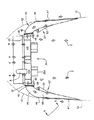
図面に示されているように、大きな大型トラック2における内燃機関(図1および8)は、エンジンブロック3と、空気吸入口5と、通路8を通って上記エンジンブロック3内から循環される冷却剤を冷却するラジエーター7とを有する。これらの全てのエンジンの構成部品は、前部10(通常は上記ラジエーターにおける、または上記ラジエーターのすぐ前)と、頂部11と、側面12とを有するエンジンコンパートメント9内に含まれる。上記頂部および上記側面の大半は、通常引き上げ可能なフード13(図8)として形成され、一般的にはトラックの下方前方端のエリアにおいて、トラックのボディーへヒンジで動くようにされている。上記エンジンコンパートメント9の後には、上記エンジンコンパートメントを運転室15から隔離する防火壁14がある。ターボチャージャー16、排気パイプ17、空気圧縮機19は、上記エンジンコンパートメント9における熱負荷を増大させる。従来の大型トラックにおいては、エンジンによって放射された熱、および、軸方向ファンによって上記エンジンコンパートメントへ吹き戻された熱は、上記エンジンコンパートメントの温度を上昇させる。ここ数年、EGR弁20を含む排気ガス再循環(EGR)システムは、特に上記EGRシステムは一般的に15%代〜30%代の高温の排気ガスを上記エンジン内へ戻して再循環させるため、上記ラジエーターへの熱負荷および上記エンジンコンパートメント内の温度をさらに増加させる。上記ラジエーター7によって放出された以外の、現代の大型トラック2のエンジンコンパートメント9内の全熱負荷は、1時間当たり約60、000BTU(63、000kJ)と推測される。
As shown in the drawings, the internal combustion engine (FIGS. 1 and 8) in a large
この本発明の具体例は、上記軸方向ファンを取り外し、好ましくは上記ラジエーターと密封された関係に、上記ラジエーター7の後に取り付けられたプレナム23を含む、隔離されたラジエーター換気システム21に交換する。そのため、トラックの前進運動中に上記ラジエーター7へ到達する全てのラムエアーは、上記ラジエーター7へ導入され、上記プレナム23内へ集中する。上記プレナム23上、好ましくはその後には、上記プレナム23内のかご形(遠心分離式)ファン27を駆動する多数のモーター25が取り付けられている。上記かご形ファン27は上記プレナムから軸方向に加熱された空気を引き、空気を90°方向を変えて、後述するように、空気ダクト43内へ外側(横方向)に放出する。
This embodiment of the present invention removes the axial fan and replaces it with an isolated
所望される場合、上記プレナム23、ファン27、空気ダクト43の後には、コーティング、または、別個の保護層またはバリアの形の保護材が設けられていてもよい。破線33によって示されているようにこの配置は、トラック2の高速道路速度の際に上記ラジエーター7によって環境へ消散される、1時間当たりに約650、000BTU(700、000kJ)以上から、エンジンコンパートメント9内のエンジン、その構成部品、および追加物を効率的に遮蔽する。このような方法での加熱された空気の排気は、エンジンコンパートメント内への熱の持続的な補強を除去する。上記エンジンコンパートメントにおける熱発生の問題は、ターボチャージャー16、EGR20、エンジンブロック3、およびその他のエンジンコンパートメント構成部品によってボンネット内で発生された、1時間当たりに60、000BTU(63、000kJ)はこのように低減される。
If desired, the
上記モーター25は、各モーターまたはモーター群が必要な時だけ作動するように、サーモスタット制御で作動する。当業者には、上記冷却ファン27の作動を制御するための予測アルゴリズムが明らかであろう。そのようなアルゴリズムは、例えば、エンジン冷却剤温度、冷却剤温度の上昇速度、エンジン表面またはオイルの温度、エンジンコンパートメントの温度、環境温度、エンジン速度、およびトラック速度などの因子を含んでいてもよい。 The motor 25 operates with thermostat control so that each motor or motor group operates only when necessary. Those skilled in the art will appreciate the prediction algorithm for controlling the operation of the cooling fan 27. Such an algorithm may include factors such as, for example, engine coolant temperature, coolant temperature rise rate, engine surface or oil temperature, engine compartment temperature, ambient temperature, engine speed, and truck speed. .
ここまでに説明した配置には、ブレードを有するファンを作動するのに必要な力(65馬力と推定される)を低減するという、さらなる利点もある。これは、かなりの燃料の節約(7〜9%)になる。また、これは、手間のかかる事項とみられているファンクラッチを除外する。上記電気かご形ファンブロアー27は、上記ブレードを有する軸方向ファンよりも遥かに効率的にラジエーター7から熱を取り去る。好ましくは多数のファンブロアー27が設けられているため、空気流は段階的に上げ下げでき、どのブロアーを作動させるか制御することによってより効率的に制御することができる。また、ファンブロアーのDCモーターは、それがオフのとき、ラムエアーからの惰性(free wheeling)でジェネレーターとなることができ、それによりトラックのバッテリーを充電できる。
The arrangement described so far has the further advantage of reducing the force required to operate a fan with blades (estimated to be 65 hp). This is a considerable fuel saving (7-9%). This also excludes fan clutches, which are considered troublesome. The electric sage fan blower 27 removes heat from the
ここまでに説明した上記隔離されたラジエーター換気システム21は、標準パッケージ35に組み入れられてもよい;広範囲の大型トラックに適合するそのようなパッケージは少ない。上記パッケージ35は、ラジエーター7、プレナム23、および複数のファン27を含んでいてもよい。そのようなパッケージは、高さが約2〜3フィート(0.5m〜1m)で、幅が約18インチ〜約36インチ(0.4m〜1m)であり、上記ラジエーターの後にフィットするサイズの、約1〜2インチ(2.5cm〜5cm)の深さのプレナム23を有するラジエーター7を含んでいてもよい。上記パッケージ35は、上記ラジエーター喚起システム21と、エンジンコンパートメント喚起システムの一部との両方を作り出すために、特定のトラックスタイルにあつらえた配管システムと対にされてもよい。
The isolated
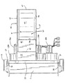
例えば図2〜図7に示すように、ラジエーターと、高さ33インチ(84cm)×幅22インチ(56cm)のプレナムとが、標準パッケージ35として提供されてもよい。上記ラジエーター7は、実例として深さ6インチ(15cm)で、その外周の回りに伸張するフランジ36を有し、上記プレナムは深さ1.25インチ(3cm)であり、上記ラジエーターの上記フランジ36に付着した外周フランジ37を含む。図3に最もよく見られるように上記プレナムには、6つのかご形ファン27A、27B、27C、27A´、27B´、27C´が取り付けられており、各ファンがそれぞれモーター25A、25B、25C、25A´、25B´、25C´と、かご形インペラー26と、側面出口39を有するハウジング38とを含む。実例として、各ファンは530cfm(1分間に15立方メートル)の空気を引き、ブラシレスの直径3インチ(7.6cm)、3000rpm、24ボルトのDCモーターを有する。上記遠心分離式ファンの引きは、特定の用途のための大きさである。上記各ファン27のハウジング38は、幅約9インチ×高さ約10インチ×深さ約4インチ(22.5×25.5×10cm)であり、各ハウジングは4インチ(10cm)の四角い出口39を有する。左上方のファン27Aと、2つの右下方のファン27B´および27C´とは同じ左右像(時計方向回転)を有し、右上方のファン27A´と、2つの左下方のファン27Bおよび27Cとは逆の左右像(時計方向回転)を有することが分かる。最下方のファン27Cおよび27C´は、それらの上方の2つのファンの出口の間に伸張する、伸張された出口39´を有し、上記プレナムの各側面上の上記全ての出口が垂直に並び、上記パッケージの各側面上に12インチ×4インチ(30×10cm)の長方形出口40を形成する。
For example, as shown in FIGS. 2-7, a radiator and a
特に図3に示されているように、各モーター25は、実例として冷却剤温度を示すT1と、エンジンコンパートメント温度を示すT2と、エンジン速度を示すRPMと、瞬間的または総合的な燃料消費を示すMPG、車両速度を示すMPHの入力を有する制御システム41へそれぞれ電気的に接続されている。これらの入力は、当業者によって容易に適用されるアルゴリズムに従って、エンジン温度が設計された範囲内に確実にとどまるように、コントローラーが上記ファン27を個別または群で作動することを可能とする。最も単純な形態においては、T1によって示される冷却剤の温度が所定の値を超えるとファンは対で作動され、T1が第二の値よりも下がると作動が停止される。それらは、T2が所定の値を超える一方でT1が比較的低い異常な状態においても、後述するように、上記エンジンコンパートメント9を冷却するために上記ファンが作動することも可能とする。RPM、MPGおよびMPHの入力は、上記冷却剤の温度がまだ上昇しているときに冷却するように、上記ラジエーターを通ってラムエアーを引き始めるように、一部または全てのファン27の予測作動を可能とする。また、上記コントローラーは、ラムエアーがそれらを通って流れ、それらの電源が入っていないときに上記トラックのバッテリーを充電するための、上記ファンの再生使用も可能とする。
Specifically, as shown in FIG. 3, each motor 25 illustratively has a T1 indicating coolant temperature, a T2 indicating engine compartment temperature, an RPM indicating engine speed, and an instantaneous or total fuel consumption. It is electrically connected to a
このラジエーター冷却パッケージ35は、ダクトシステム43と対にされる。ダクトシステム43の少なくとも後方部分は、必須ではないが、上記ボンネット13の内側へ取り付けられることが好ましい。上記ボンネットに取り付けられたダクト43と、上記パッケージ35との間の接合点は、任意の公知の方法によってシールすることができる。例えば、図2および図3だけで示されているように、上記パッケージ35の上記長方形出口40は、上記ボンネンットに取り付けられたダクト上の補完的に傾斜された斜面とシールするためのガスケットをその開口(上方)面に有する、複合斜面(compound bevel)42において終結してもよい。この配置は、上記ボンネンット13のスムーズな開閉を可能とし、上記ボンネット13が閉じられているときに上記ダクトシステム43を上記パッケージ35へシールする。また、上記パッケージダクトまたは上記ボンネットに取り付けられたダクトの端部は、上記ダクトの他の部分と対にするために、自動または手動の作動機構を介して縦方向に動かせてもよい。同様に、上記ダクトシステムは上記ラジエーター換気システムパッケージ35へ恒久的に取り付けられてもよく、上記ボンネンットの各側面12における開口部と単に調整されてもよい。
This
この実例となる態様における上記ダクトシステム43は、上記出口40の前方壁と対にされた曲がった外壁(outside wall)44と、上記出口40の後方壁と対にされた曲がった内壁(inside wall)45とを含む。上記外壁44は、トラックのボンネットの側面壁12における同じような大きさの長方形開口部と調整された外周縁47を有する略平坦な垂直長方形開口部46において終結する。この開口部の形状は、上記トラックのボンネットの輪郭によってある程度影響を受けることに留意すべきである。この態様においては、上記開口部46は大体高さ12インチ(30cm)で、上記ラジエーター換気パッケージの出口40と同じ高さである。上記ダクトシステム43の内壁45は、上記出口40へ取り付けられた曲がった入口部に沿って、上記外壁44から4インチ離間している。上記開口部46の反対側の位置へ内側壁45が到達すると、それはその後上記開口部46の後方端47内へ、なだらかに後方へ曲がる。上記外壁および内壁44および45は、上方および下方の水平壁48によって互いに連結される。上記壁44、45および48は、上記ラジエーター換気システム21から、トラックが前方へ移動しているときの大型トラックの環境後流(ambient slip stream)へと排気された空気を導く、平坦な開放溝を形成することが分かる。
The
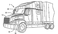
上記エンジンブロック3および上記エンジンコンパートメントにおける関連のボンネット内の構成部品を冷却するために、別個のエンジンコンパートメント換気システム51が提供される。この実例となる態様における上記第二の換気システム51は、上記エンジンコンパートメントにおいて生じた熱を、1時間当たりに約60、000BTU(63、000kJ)除去するような大きさとされる。概して、1時間当たりに60、000BTU(63、000kJ)は、冷たいラムエアーをエンジンコンパートメント内へ流すためにフロントガラスにおける高圧領域を利用して、ラジエーターファンの空気の環境への出口に隣接した低圧領域内へ空気を引くようにアレンジされたボンネット側面ダクトを介して上記エンジンコンパートメントの空気が出ることを招く、上記ボンネットの頂部に戦略的に配置されたカウル吸気によって、効率的に制御することができる。図1、2および8に示されるように、上記エンジンコンパートメント換気システム51は、トラック2のフロントガラス55の前に吸気カウル53を含む。カウル吸気システムは、レースカーにおいて長年用いられて来たが、大型トラックにおけるそれらの使用は新規であると考える。知られているように、上記カウル53の後方56、フロントガラスの近くは、上記エンジンコンパートメントへ開放している。作動速度においては、比較的低い作動速度においても、空気は上記フロントガラス55の土台において圧縮され、56において示されているように、上記カウル53の後方を介して上記エンジンコンパートメント内へ引き込まれる。
A separate engine
特に図2〜図6に示されているように、上記エンジンコンパートメント9内の空気は、上記ダクト43の内壁45上に取り付けられた空気出口ダクト57を介して放出される。特に図3および4見られるように上記出口ダクト57は、この態様では、それらの口59において高さ約9インチ幅3インチ(23cm×8cm)であり、上記ダクト43の内側壁45上に、垂直方向の中心にある。上記ダクト43の内壁45は、出口ダクト57が流入する、長方形開口部61を含む。各出口ダクト57は、その後方において上記内壁45と接触するように曲がっている垂直内側壁(inner wall)63と、上記出口ダクトの上記内側壁63を上記ラジエーター換気ダクト43の上記内側壁45へ接合する上方および下方水平壁65とを含む。上記出口ダクト57は環境に対して完全に開口しているが、それらは上記ラジエーター換気システム21の出口46を介して強制的に放出される熱い空気の後流内でもあり、上記トラックの後流内でもある。従って空気は、出口46を介した上記プレナムからの熱い空気の流れによって生じたベンチュリー効果によって上記エンジンコンパートメントの外にさらに引かれる。上記トラック2の前進移動も、上記ダクト43の出口46およびエンジンコンパートメント9からの出口57の両方から熱い空気を引く傾向にある後流を生じさせる。起こりそうにない状況において、上記ファン27が作動していないときに上記エンジンコンパートメントが望ましくない温度に達した場合は、上記ダクト43を介して空気を引き、上記エンジンコンパートメント9の外に空気を吸うために、上記ファンモーター25を作動させることができる。
As shown particularly in FIGS. 2 to 6, the air in the engine compartment 9 is discharged through an
図1および図2に示されているように、上記大型トラックの前方において矢印Rによって示されるラムエアーは、上記ラジエーター7を介して完全に上記ラジエーター換気システム21内へと導かれる一方、上記エンジンコンパートメント9は矢印Cによって示され、上記エンジンコンパートメントの後方から前方へ徐々に移動するカウル吸気によって冷却される。上記エンジンコンパートメント9の後から前への空気の移動は、防火壁14の領域から熱を除去し、上記運転室15への熱負荷を低減する。
As shown in FIGS. 1 and 2, the ram air indicated by the arrow R in front of the heavy truck is completely led through the
全てのアクセス可能な開口部上に、適切な安全覆いが設けられていることが好ましい。数々のそのような安全覆いが公知であり、例えば薄い水平な羽根などがある。 Appropriate safety covers are preferably provided on all accessible openings. A number of such safety covers are known, such as thin horizontal vanes.
上記開示を踏まえ、添付のクレームの範囲内において、本発明の車両のボンネンット内の温度制御システムにおける数々のバリエーションが当業者に可能である。単に例として、上記ラジエーターを冷却するための他の閉鎖系システムが提供されてもよい。上述したように、図8に例示するように、異なるトラックの形状およびエンジンコンパートメントに適合するように、上記排気ダクトの配置および寸法はもちろん変えられてもよい。上記エンジンコンパートメント冷却システムは、吸気システムおよびラムエアー入口を含む、他の空気入口をエンジンコンパートメントの上面または側面に有していてもよい。上記空気入口は、上記トラックの前方から離れていることが好ましい。一般的にラムエアー入口は、キャブオーバーデザインにおける使用以外においては、現在は好まれていない。上記エンジンコンパートメント冷却システムは、他の出口ポートを有していてもよく、所望により種々の動力ファンを有していてもよい。例えば、上記エンジンコンパートメント換気システムの出口に、動力ファンが提供されてもよい。上記ファンの作動を制御するため、または、調節板等を動かすために、多くの温度制御システムが知られており、また、容易に適合させることができる。実例となる態様においては、例えば変速モーター、より望ましくはないが油圧モーターを含む他のモーターが上記かご形ファンを作動するために用いられてもよい;用途に応じて、ファンの寸法や数が変更されてもよい;特定の用途の要求に合うように、上記かご形ファンのブレードの形状、数、および寸法が変更されてもよい。電気ファンモーターは、例えば12V〜24Vの異なる電圧で駆動されてもよい。上記エンジンコンパートメントの底は、空気力学的、または、内部の空気流の目的で、取り囲まれていてもよい。これらのバリエーションは単なる実例である。本発明の範囲を逸脱することなく上述した構成において様々な変更が可能であるため、上記説明または添付の図面に示される全ての事柄は、限定的な解釈ではなく、実例として解されることを意図する。 In light of the above disclosure, numerous variations on the temperature control system within the vehicle bonnet of the present invention are possible to those skilled in the art within the scope of the appended claims. By way of example only, other closed system systems for cooling the radiator may be provided. As described above, the exhaust duct placement and dimensions may of course be varied to accommodate different truck shapes and engine compartments, as illustrated in FIG. The engine compartment cooling system may have other air inlets on the top or side of the engine compartment, including an intake system and a ram air inlet. The air inlet is preferably remote from the front of the truck. In general, ram air inlets are not currently preferred except for use in cab over design. The engine compartment cooling system may have other outlet ports and may have various power fans as desired. For example, a power fan may be provided at the outlet of the engine compartment ventilation system. Many temperature control systems are known and can be easily adapted to control the operation of the fan or to move the adjustment plate or the like. In illustrative embodiments, other motors may be used to operate the squirrel fan, including, for example, variable speed motors, and less preferably hydraulic motors; depending on the application, the size and number of fans may vary. The shape, number, and dimensions of the cage fan blades may be changed to meet the needs of a particular application. The electric fan motor may be driven with a different voltage of, for example, 12V to 24V. The bottom of the engine compartment may be surrounded for aerodynamic or internal air flow purposes. These variations are merely illustrative. Since various modifications can be made in the above-described configurations without departing from the scope of the present invention, all matters shown in the above description or accompanying drawings should be understood as illustrative rather than limiting. Intended.
ここに記載された全ての特許および特許出願は、参照することにより本願の一部を構成する。 All patents and patent applications mentioned herein are hereby incorporated by reference.
Claims (6)
エンジンコンパートメントと;
前記エンジンコンパートメント内のエンジンと;
前記エンジンの前にあり、前記エンジンから冷却剤を受け取るラジエーターと;
前記ラジエーターの後の第一換気システムであって、環境へ排気出口を有するダクトと、前記ダクトを介して前記ラジエーターを介して空気を引き、前記第一換気システムの排気出口から出すために適応された少なくとも一つの電気ファンとを含み、前記ラジエーターを介して引かれた空気が前記エンジンコンパートメントへ入ることを防ぐように構成された第一換気システムと;
前記エンジンコンパートメントから熱を除去するように構成された第二換気システムであって、前記エンジンコンパートメントの後方部分へ環境の空気を流し、前記エンジンコンパートメントの前方部分へ向けた排気出口から、前記エンジンコンパートメントによって加熱された空気を排気するように構成された第二換気システムと、を有する路上の道路走行が可能な車両。 With the cab;
With engine compartment;
An engine in the engine compartment;
A radiator in front of the engine for receiving coolant from the engine;
A first ventilation system after the radiator, wherein the duct has an exhaust outlet to the environment and adapted to draw air through the radiator through the duct and out of the exhaust outlet of the first ventilation system; And a first ventilation system configured to prevent air drawn through the radiator from entering the engine compartment;
A second ventilation system configured to remove heat from the engine compartment, wherein ambient air flows to a rear portion of the engine compartment and from an exhaust outlet toward the front portion of the engine compartment, the engine compartment And a second ventilation system configured to exhaust air heated by the vehicle.
前記吸気構造が、前記車両が前方へ移動しているときに前記エンジンコンパートメント内へ環境の空気を流すように適合されていることを特徴とする請求項1に記載の車両。 The second ventilation system further comprises an intake structure on at least one of the top or sides of the engine compartment;
The vehicle of claim 1, wherein the intake structure is adapted to flow ambient air into the engine compartment when the vehicle is moving forward.
時速97kmの高速道路速度の能力があることを特徴とする請求項1に記載の車両。 The vehicle has a gross vehicle weight of at least 6350 kg;
The vehicle according to claim 1, which is capable of highway speed of 97 km / h.
前記運転室の前方壁の一部を形成するフロントガラスと;
前記運転室の前のエンジンコンパートメントと;
前記エンジンコンパートメント内のエンジンと;
前記エンジンの前にあり、前記エンジンから冷却剤を受け取るラジエーターと;
前記ラジエーターの後の第一換気システムであって、前記ラジエーターを介して引かれた空気が前記エンジンコンパートメントへ入ることを防ぐ第一換気システムと;
前記車両が前方へ移動しているときに前記エンジンコンパートメント内へ空気を流すように構成された第二換気システムであって、前記フロントガラスの土台の近くに空気入口を有する第二換気システムと;を有する車両であって、
前記フロントガラスは、前記車両が前方へ移動しているときに前記第二換気システムの入口へ空気を流すために、その土台に高圧領域を形成することを特徴とする、路上の道路走行が可能な車両。 With the cab;
A windshield forming part of the front wall of the cab;
An engine compartment in front of the cab;
An engine in the engine compartment;
A radiator in front of the engine for receiving coolant from the engine;
A first ventilation system after the radiator, the first ventilation system preventing air drawn through the radiator from entering the engine compartment;
A second ventilation system configured to flow air into the engine compartment when the vehicle is moving forward, the second ventilation system having an air inlet near a base of the windshield; A vehicle having
The windshield is capable of road driving on the road, characterized in that it forms a high pressure area on its foundation to allow air to flow to the entrance of the second ventilation system when the vehicle is moving forward Vehicle.
前記車両の前方において、ラムエアーがラジエーターを介して入り、前記エンジンコンパートメントから独立したラジエーター換気システムへ入るように導き、
前記エンジンコンパートメントの後方から前方へ穏やかに移動するカウル吸気によって前記エンジンコンパートメントを冷却すること、を含む方法。 A method of handling air in an engine compartment in front of a cab of a vehicle moving forward,
In front of the vehicle, ram air enters via a radiator and leads to a radiator ventilation system independent of the engine compartment,
Cooling the engine compartment by a cowl intake that moves gently from the rear to the front of the engine compartment.
Applications Claiming Priority (3)
| Application Number | Priority Date | Filing Date | Title |
|---|---|---|---|
| US86374006P | 2006-10-31 | 2006-10-31 | |
| US60/863,740 | 2006-10-31 | ||
| PCT/US2007/083190 WO2008055216A2 (en) | 2006-10-31 | 2007-10-31 | Air management system for truck |
Publications (3)
| Publication Number | Publication Date |
|---|---|
| JP2010508206A JP2010508206A (en) | 2010-03-18 |
| JP2010508206A5 JP2010508206A5 (en) | 2010-12-24 |
| JP5323711B2 true JP5323711B2 (en) | 2013-10-23 |
Family
ID=39345079
Family Applications (1)
| Application Number | Title | Priority Date | Filing Date |
|---|---|---|---|
| JP2009535446A Expired - Fee Related JP5323711B2 (en) | 2006-10-31 | 2007-10-31 | Air management system for temperature control in heavy truck bonnet |
Country Status (12)
| Country | Link |
|---|---|
| US (5) | US7537072B2 (en) |
| EP (1) | EP2081790B1 (en) |
| JP (1) | JP5323711B2 (en) |
| KR (1) | KR101422548B1 (en) |
| CN (1) | CN101547809B (en) |
| AU (1) | AU2007313695B2 (en) |
| BR (1) | BRPI0718255B1 (en) |
| CA (1) | CA2667958C (en) |
| MX (1) | MX2009004614A (en) |
| RU (1) | RU2460652C2 (en) |
| WO (1) | WO2008055216A2 (en) |
| ZA (1) | ZA200902997B (en) |
Families Citing this family (53)
| Publication number | Priority date | Publication date | Assignee | Title |
|---|---|---|---|---|
| JP4847073B2 (en) * | 2005-08-29 | 2011-12-28 | ヤンマー株式会社 | Tractor |
| EP2011977A1 (en) * | 2006-04-04 | 2009-01-07 | Calsonic Kansei Corporation | Heat exchanger for vehicle |
| DE102008021259A1 (en) * | 2008-04-29 | 2009-11-05 | Bayerische Motoren Werke Aktiengesellschaft | Motor vehicle, has bonnet limiting engine compartment on top side, where ambient air entering through inlet port is guided to lateral discharge opening formed within area of A-column of body of motor vehicle during driving |
| WO2009142555A1 (en) * | 2008-05-23 | 2009-11-26 | Volvo Construction Equipment Ab | Ventilating system for ventilating an engine space in vehicle, a vehicle comprising the ventilating system and a work machine comprising the ventilating system |
| US20100301638A1 (en) * | 2009-05-29 | 2010-12-02 | Hinshaw Eric J | Integrated Air Intake System |
| JP5331666B2 (en) * | 2009-11-30 | 2013-10-30 | 株式会社日立製作所 | Electric vehicle cooling system |
| US8622162B2 (en) * | 2009-12-11 | 2014-01-07 | Thomas Karl | Engine compartment cooling system |
| JP5171888B2 (en) * | 2010-06-09 | 2013-03-27 | 日立建機株式会社 | Construction machinery |
| IT1401209B1 (en) * | 2010-07-02 | 2013-07-12 | Cnh Italia Spa | CABIN FOR AGRICULTURAL VEHICLE EQUIPPED WITH A VENTILATION AND AIR-CONDITIONING SYSTEM |
| US8919469B2 (en) * | 2010-08-26 | 2014-12-30 | Caterpillar Inc. | Ventilation system for engine and aftertreatment compartments and components |
| JP5329519B2 (en) * | 2010-12-27 | 2013-10-30 | 日立建機株式会社 | Construction machinery |
| KR101231539B1 (en) * | 2011-03-10 | 2013-02-07 | 기아자동차주식회사 | Wind Flux Concentration Guiding Device and Engine Room Layout Thereof |
| US8757300B2 (en) * | 2011-03-17 | 2014-06-24 | Toyota Motor Engineering & Manufacturing North America, Inc. | Ram air generator for an automobile |
| US8939733B2 (en) * | 2011-06-22 | 2015-01-27 | Caterpillar Inc. | Hydraulic fan assembly for an engine ventilation system |
| US8453777B2 (en) * | 2011-10-24 | 2013-06-04 | Deere & Company | Cooling fan duct assembly |
| KR20130050051A (en) * | 2011-11-07 | 2013-05-15 | 현대자동차주식회사 | Cooling apparatus for vehicle |
| GB2497143B (en) * | 2012-01-20 | 2014-07-30 | Jaguar Land Rover Ltd | Motor vehicle with improved air intake apparatus |
| JP5948966B2 (en) * | 2012-03-01 | 2016-07-06 | コベルコ建機株式会社 | Construction machine intake structure |
| WO2013161010A1 (en) * | 2012-04-24 | 2013-10-31 | トヨタ自動車株式会社 | Cooling device for vehicle |
| US8960136B2 (en) | 2012-05-17 | 2015-02-24 | Spartan Motors, Inc. | Method and apparatus for managing airflow and powertrain cooling |
| CN104395164B (en) * | 2012-07-05 | 2017-04-19 | 沃尔沃建造设备有限公司 | Battery charging system for hybrid construction machinery by using rotational force of fan and charging method therefor |
| EP2792795B1 (en) * | 2013-02-22 | 2015-04-08 | Komatsu Ltd. | Wheel loader |
| US10363811B2 (en) * | 2013-06-13 | 2019-07-30 | Ford Global Technologies, Llc | Vehicle speed controlled active grille shutter system |
| JP6126954B2 (en) * | 2013-09-11 | 2017-05-10 | 本田技研工業株式会社 | Saddle riding vehicle |
| JP5636512B1 (en) * | 2013-09-25 | 2014-12-03 | 株式会社小松製作所 | Work vehicle |
| EP2899230A1 (en) | 2014-01-22 | 2015-07-29 | Solvay Specialty Polymers USA, LLC. | Automotive articles |
| FR3018743B1 (en) * | 2014-03-18 | 2016-03-25 | Peugeot Citroen Automobiles Sa | AUTOMOTIVE VEHICLE AIR COOLING AIR COOLER GRILLE |
| JP5629845B1 (en) * | 2014-03-31 | 2014-11-26 | 株式会社小松製作所 | Work vehicle |
| JP2015217829A (en) * | 2014-05-19 | 2015-12-07 | 本田技研工業株式会社 | Vehicle cooling structure |
| DE102014008477B4 (en) * | 2014-06-05 | 2019-07-04 | Liebherr-Mining Equipment Colmar Sas | Dump truck or truck with a diesel-electric traction drive, a cooling system and a hydraulic motor |
| DE102014109811A1 (en) * | 2014-07-14 | 2016-01-14 | Dr. Ing. H.C. F. Porsche Aktiengesellschaft | Air guiding device for exhaust air guidance |
| GB2531544A (en) * | 2014-10-21 | 2016-04-27 | Daimler Ag | Grille for a vehicle, in particular a commercial vehicle as well as a vehicle |
| DE102014117007A1 (en) * | 2014-11-20 | 2016-05-25 | Valeo Klimasysteme Gmbh | Cooling module of a vehicle air conditioning system and assembly for cooling a motor vehicle engine with such a cooling module |
| JP6380212B2 (en) * | 2014-12-09 | 2018-08-29 | 株式会社デンソー | Cooling device and cooling module |
| USD765740S1 (en) | 2015-06-17 | 2016-09-06 | Cnh Industrial America Llc | Engine hood of an agricultural vehicle |
| USD766340S1 (en) | 2015-06-17 | 2016-09-13 | Cnh Industrial America Llc | Engine hood of an agricultural vehicle |
| US10059192B2 (en) | 2015-06-17 | 2018-08-28 | Cnh Industrial America Llc | System and method for adjusting air flow in an engine compartment of an off-road vehicle |
| USD753195S1 (en) | 2015-06-17 | 2016-04-05 | Cnh Industrial America Llc | Engine hood of an agricultural vehicle |
| KR20170005561A (en) * | 2015-07-06 | 2017-01-16 | 현대자동차주식회사 | Under cover for heat suction |
| US10450939B2 (en) | 2016-04-28 | 2019-10-22 | Deere & Company | Multiple plane recirculation fan control for a cooling package |
| FR3052856B1 (en) * | 2016-06-21 | 2019-06-14 | Valeo Systemes Thermiques | CIRCULATING LOOP OF A REFRIGERANT FLUID FOR A VEHICLE |
| US10059330B2 (en) | 2016-09-22 | 2018-08-28 | Toyota Motor Engineering & Manufacturing North America, Inc. | Drafting detection and vehicle operation optimization system |
| US9897121B1 (en) * | 2016-09-28 | 2018-02-20 | Atieva, Inc. | Automotive air intake utilizing a vortex generating airflow system |
| FR3063686A1 (en) * | 2017-03-09 | 2018-09-14 | Gilbert Camara | DEVICE FOR CHANNELING AND MANAGING THE FLOW OF COOLING AIR FLOW OF A VEHICLE AND SUPPORTING ONE OR MORE EOLIANS ELECTRIC GENERATORS. |
| KR102215763B1 (en) * | 2017-03-14 | 2021-02-15 | 현대자동차주식회사 | Structure of duct for cooling brake |
| CN106989618A (en) * | 2017-04-26 | 2017-07-28 | 贵州理工学院 | Cooling system inside large volume goaf filling body |
| US20180354355A1 (en) * | 2017-06-12 | 2018-12-13 | Paccar Inc | Air ducts for airflow management, and associated systems and methods |
| CN108625971A (en) * | 2018-04-28 | 2018-10-09 | 泰铂(上海)环保科技股份有限公司 | A kind of the automobile cooling device and application method of band centrifugation fan structure |
| WO2019231701A2 (en) | 2018-05-29 | 2019-12-05 | Achates Power, Inc. | Opposed-piston engine in a light-dight-duty truck |
| FR3096308A1 (en) * | 2019-05-24 | 2020-11-27 | Valeo Systemes Thermiques | TANGENTIAL TURBOMACHINE ELECTRIC MOTOR VEHICLE COOLING MODULE |
| CN112761770A (en) * | 2019-11-06 | 2021-05-07 | 广州汽车集团股份有限公司 | Cooling device beneficial to heat dissipation of automobile engine room |
| US11384680B2 (en) * | 2019-12-30 | 2022-07-12 | Woven Planet North America, Inc. | Systems and methods for automobile radiator cooling control |
| CN114961961A (en) * | 2021-02-19 | 2022-08-30 | Tvs电机股份有限公司 | Cooling assembly for internal combustion engine |
Family Cites Families (59)
| Publication number | Priority date | Publication date | Assignee | Title |
|---|---|---|---|---|
| US2242494A (en) | 1932-04-07 | 1941-05-20 | Austin M Wolf | Ventilating and cooling system for motor vehicles |
| US3232368A (en) | 1963-10-14 | 1966-02-01 | Int Harvester Co | Motor truck body structure and mounting means therefor |
| DE2133737A1 (en) * | 1971-07-07 | 1973-01-18 | Daimler Benz Ag | CAB OF COMMERCIAL VEHICLES |
| AT354863B (en) * | 1975-06-13 | 1980-02-11 | List Hans | MOTOR VEHICLE WITH A SOUND INSULATING CAPSULE FOR THE ENGINE OR. THE ENGINE-GEAR UNIT |
| US4235298A (en) * | 1979-02-28 | 1980-11-25 | Freightliner Corporation | Truck or truck tractor windshield air ram arrangement |
| US4372409A (en) | 1980-07-28 | 1983-02-08 | Eaton Corporation | Cross-flow fan for transverse engine vehicle |
| US4382481A (en) * | 1981-02-02 | 1983-05-10 | Dresser Industries, Inc. | Dual fan engine cooling system |
| US4417636A (en) | 1981-06-22 | 1983-11-29 | Eaton Corporation | Cooling fan ducting |
| DE3322338A1 (en) * | 1982-07-01 | 1984-01-05 | AVL Gesellschaft für Verbrennungskraftmaschinen und Messtechnik mbH, Prof. Dr.Dr.H.C. Hans List, 8020 Graz | MOTOR VEHICLE WITH A WATER-COOLED INTERNAL COMBUSTION ENGINE AS A DRIVE ENGINE |
| US4519343A (en) | 1982-11-08 | 1985-05-28 | Aisin Seiki Kabushiki Kaisha | Engine cooling system |
| DE3321804A1 (en) * | 1983-06-16 | 1984-12-20 | Daimler-Benz Ag, 7000 Stuttgart | DEVICE FOR EXHAUSTING WARM AIR FROM THE ENGINE ROOM OF A VEHICLE |
| US4726326A (en) | 1983-09-26 | 1988-02-23 | Charles Herbert N | Drag reducing cooling system for a vehicle |
| US4597463A (en) * | 1984-01-23 | 1986-07-01 | Richard Barnard | Electric vehicle using the vehicle's kinetic and mechanical power to regenerate it's energy storage device |
| DE8427839U1 (en) * | 1984-09-21 | 1985-02-07 | Dr.Ing.H.C. F. Porsche Ag, 7000 Stuttgart | MOTOR VEHICLE WITH A BOW-SIDED RADIATOR ARRANGEMENT, INCLUDING FRONT AIR INLETS AND SIDE VENTILATION OPENINGS |
| GB2174652A (en) | 1985-05-09 | 1986-11-12 | Ford Motor Co | Engine cooling system |
| JPS6229928U (en) * | 1985-08-08 | 1987-02-23 | ||
| JPH01141163A (en) | 1986-02-11 | 1989-06-02 | Alsthom Atlantique Sa | Ventilatign device for fluid cooling and/or rheostat of locomotive |
| US4778029A (en) * | 1987-04-29 | 1988-10-18 | General Motors Coporation | Engine air inlet and silencer for motor vehicle |
| JPH01111140U (en) * | 1988-01-18 | 1989-07-26 | ||
| JPH07664Y2 (en) * | 1988-03-30 | 1995-01-11 | カルソニック株式会社 | Car cooling system |
| JP2621044B2 (en) * | 1988-04-22 | 1997-06-18 | スズキ株式会社 | Car engine room ventilation structure |
| US4846258A (en) * | 1988-06-03 | 1989-07-11 | Bendix Electronics Limited | Non-ram cooling system |
| US4979584A (en) | 1989-05-25 | 1990-12-25 | Siemens-Bendix Automotive Electronics Limited | Automotive vehicle engine bay ventilation |
| US4971172A (en) | 1989-06-30 | 1990-11-20 | Navistar International Transportation Corp. | Truck hood engine air induction system |
| US5046554A (en) | 1990-02-22 | 1991-09-10 | Calsonic International, Inc. | Cooling module |
| JP3116231B2 (en) | 1990-02-28 | 2000-12-11 | 臼井国際産業株式会社 | Radiator radiator using air duct |
| US5193609A (en) | 1990-04-19 | 1993-03-16 | Cowart Darrow W | Low profile heating and colling unit for vehicles |
| US5042603A (en) | 1990-04-23 | 1991-08-27 | Navistar International Transportation Corp. | Engine air intake apparatus |
| EP0564522B1 (en) | 1991-01-03 | 1995-08-09 | Siemens Aktiengesellschaft | Automotive vehicle engine bay ventilation by ducted-fan-operated ejector |
| DE4122512A1 (en) | 1991-05-28 | 1992-12-03 | Kloeckner Humboldt Deutz Ag | COMPACT HEAT EXCHANGER FAN UNIT |
| JPH07664A (en) * | 1993-06-14 | 1995-01-06 | Hirose Mfg Co Ltd | Sewing machine part |
| US5588482A (en) * | 1994-09-26 | 1996-12-31 | Ford Motor Company | Ducted cooling system for an automotive vehicle |
| US5579858A (en) * | 1994-10-31 | 1996-12-03 | Ford Motor Company | Automotive air intake assembly |
| US5590624A (en) * | 1995-03-31 | 1997-01-07 | Caterpillar Inc. | Engine cooling systems |
| US5632673A (en) * | 1995-10-30 | 1997-05-27 | Chrysler Corporation | Ventilation system for lightweight automobile |
| US5775450A (en) | 1996-05-06 | 1998-07-07 | General Motors Corporation | Vehicle underhood component cooling system |
| US5794733A (en) * | 1996-08-16 | 1998-08-18 | Volvo Gm Heavy Truck Corporation | Vehicle air intake and method |
| US6230832B1 (en) * | 1996-09-04 | 2001-05-15 | Freightliner Llc | Truck underhood air flow management system |
| US6142213A (en) | 1997-11-25 | 2000-11-07 | Siemens Canada Limited | Ducted cooling system with radial-flow fan |
| US6059061A (en) * | 1998-07-22 | 2000-05-09 | Economoff; Peter P. | Air cooling of vehicle radiators |
| US6216778B1 (en) | 1998-12-30 | 2001-04-17 | Case Corporation | Cooling system for an off-highway vehicle |
| DE19950753A1 (en) | 1999-10-21 | 2001-04-26 | Modine Mfg Co | Cooling system I |
| US6401801B1 (en) * | 1999-12-10 | 2002-06-11 | Caterpillar Inc. | Twin fan cooling system |
| US6463891B2 (en) | 1999-12-17 | 2002-10-15 | Caterpillar Inc. | Twin fan control system and method |
| JP2002021565A (en) * | 2000-07-11 | 2002-01-23 | Komatsu Ltd | Engine enclosure for construction vehicle |
| US6491502B2 (en) | 2000-08-23 | 2002-12-10 | Siemens Canada Limited | Center mounted fan module with even airflow distribution features |
| DE10052331A1 (en) * | 2000-10-17 | 2002-05-02 | Stribel Gmbh | A fan installation |
| US6354096B1 (en) * | 2000-10-20 | 2002-03-12 | Nicholas R. Siler | Vehicular cooling system |
| DE10053146A1 (en) | 2000-10-26 | 2002-05-08 | Mann & Hummel Filter | intake system |
| DE10119591A1 (en) | 2001-04-21 | 2002-10-24 | Modine Mfg Co | Cooling system for motor vehicles |
| DE10120483A1 (en) | 2001-04-25 | 2002-10-31 | Modine Mfg Co | Arrangement for cooling |
| AT5483U1 (en) * | 2001-07-02 | 2002-07-25 | Avl List Gmbh | SHUTTER FOR LOCKING OPENINGS |
| EP1284343B1 (en) | 2001-08-17 | 2008-07-30 | Behr GmbH & Co. KG | Cooling system for a motor vehicle and related motor vehicle |
| US6809484B2 (en) * | 2001-09-25 | 2004-10-26 | Siemens Vdo Automotive Inc. | Multiple electronically commutated motor control apparatus and method |
| US6871697B2 (en) * | 2002-01-18 | 2005-03-29 | Clark Equipment Company | Integrated fluid reservoir and heat exchanger ducts |
| US6732681B1 (en) | 2003-02-19 | 2004-05-11 | International Truck Intellectual Property Company, Llc | Modular engine cooling system with hydraulic fan drive |
| JP4179088B2 (en) * | 2003-07-24 | 2008-11-12 | 株式会社デンソー | Vehicle cooling system |
| US20050224267A1 (en) * | 2004-04-08 | 2005-10-13 | Callas James J | Cooling system for a vehicular engine |
| US7406835B2 (en) * | 2005-05-10 | 2008-08-05 | Emp Advanced Development, Llc | Cooling system and method for cooling a heat producing system |
-
2007
- 2007-10-31 BR BRPI0718255A patent/BRPI0718255B1/en not_active IP Right Cessation
- 2007-10-31 JP JP2009535446A patent/JP5323711B2/en not_active Expired - Fee Related
- 2007-10-31 RU RU2009120563/11A patent/RU2460652C2/en not_active IP Right Cessation
- 2007-10-31 CN CN2007800408095A patent/CN101547809B/en not_active Expired - Fee Related
- 2007-10-31 MX MX2009004614A patent/MX2009004614A/en active IP Right Grant
- 2007-10-31 EP EP07863715.4A patent/EP2081790B1/en active Active
- 2007-10-31 US US11/932,393 patent/US7537072B2/en active Active
- 2007-10-31 KR KR1020097008839A patent/KR101422548B1/en active IP Right Grant
- 2007-10-31 WO PCT/US2007/083190 patent/WO2008055216A2/en active Application Filing
- 2007-10-31 AU AU2007313695A patent/AU2007313695B2/en not_active Ceased
- 2007-10-31 CA CA2667958A patent/CA2667958C/en active Active
-
2009
- 2009-04-21 US US12/427,400 patent/US8556013B2/en active Active
- 2009-04-30 ZA ZA200902997A patent/ZA200902997B/en unknown
-
2012
- 2012-08-21 US US13/590,616 patent/US20120318593A1/en not_active Abandoned
-
2014
- 2014-04-07 US US14/247,069 patent/US9470135B2/en active Active
-
2016
- 2016-10-17 US US15/295,624 patent/US20170030256A1/en not_active Abandoned
Also Published As
| Publication number | Publication date |
|---|---|
| CA2667958A1 (en) | 2008-05-08 |
| MX2009004614A (en) | 2009-07-02 |
| US20170030256A1 (en) | 2017-02-02 |
| EP2081790A4 (en) | 2011-08-17 |
| CA2667958C (en) | 2012-01-03 |
| KR20090085042A (en) | 2009-08-06 |
| EP2081790A2 (en) | 2009-07-29 |
| CN101547809A (en) | 2009-09-30 |
| BRPI0718255A2 (en) | 2014-01-21 |
| US20140230759A1 (en) | 2014-08-21 |
| AU2007313695A1 (en) | 2008-05-08 |
| WO2008055216A2 (en) | 2008-05-08 |
| US20090277706A1 (en) | 2009-11-12 |
| BRPI0718255B1 (en) | 2020-04-22 |
| KR101422548B1 (en) | 2014-07-24 |
| US20120318593A1 (en) | 2012-12-20 |
| ZA200902997B (en) | 2010-03-31 |
| JP2010508206A (en) | 2010-03-18 |
| WO2008055216A3 (en) | 2008-10-09 |
| EP2081790B1 (en) | 2013-10-23 |
| US7537072B2 (en) | 2009-05-26 |
| RU2460652C2 (en) | 2012-09-10 |
| US9470135B2 (en) | 2016-10-18 |
| US8556013B2 (en) | 2013-10-15 |
| US20080099261A1 (en) | 2008-05-01 |
| AU2007313695B2 (en) | 2012-07-05 |
| RU2009120563A (en) | 2010-12-10 |
| CN101547809B (en) | 2013-07-17 |
Similar Documents
| Publication | Publication Date | Title |
|---|---|---|
| JP5323711B2 (en) | Air management system for temperature control in heavy truck bonnet | |
| CN107521330B (en) | Method and system for a vehicle cooling system | |
| CN102619605B (en) | For the vent systems of construction machine | |
| JP2010508206A5 (en) | ||
| CN108397273B (en) | Cooling fan for engine cooling system | |
| EP1676739A1 (en) | Cooling device for a vehicle engine | |
| US10900499B2 (en) | Cooling fans for engine cooling system | |
| JPH05301528A (en) | Ventilating device for automobile engine room | |
| JP4547426B2 (en) | Automotive cooling system | |
| AU2012238213B2 (en) | Air Management System for Truck | |
| JP2006218975A (en) | Vehicular radiator | |
| RU2385808C1 (en) | Radiator cooling system | |
| SE539042C2 (en) | Device for engine room ventilation with self-draw | |
| JP4161820B2 (en) | Vehicle heat exchanger cooling structure | |
| JPH0428826Y2 (en) | ||
| JP2018075925A (en) | Vehicle cooler structure | |
| JP2005246995A (en) | Front vehicle body structure | |
| GB2562228A (en) | Heat Retention apparatus and method | |
| JP2004340322A (en) | Transmission cooling device | |
| GB2562232A (en) | Heat retention structure and method | |
| JPH04362421A (en) | Engine cooling device for vehicle | |
| JP2002097953A (en) | Internal combustion engine cooling device of working vehicle |
Legal Events
| Date | Code | Title | Description |
|---|---|---|---|
| A521 | Request for written amendment filed |
Free format text: JAPANESE INTERMEDIATE CODE: A523 Effective date: 20101101 |
|
| A621 | Written request for application examination |
Free format text: JAPANESE INTERMEDIATE CODE: A621 Effective date: 20101101 |
|
| RD04 | Notification of resignation of power of attorney |
Free format text: JAPANESE INTERMEDIATE CODE: A7424 Effective date: 20120704 |
|
| A977 | Report on retrieval |
Free format text: JAPANESE INTERMEDIATE CODE: A971007 Effective date: 20120831 |
|
| A131 | Notification of reasons for refusal |
Free format text: JAPANESE INTERMEDIATE CODE: A131 Effective date: 20120904 |
|
| A601 | Written request for extension of time |
Free format text: JAPANESE INTERMEDIATE CODE: A601 Effective date: 20121203 |
|
| A602 | Written permission of extension of time |
Free format text: JAPANESE INTERMEDIATE CODE: A602 Effective date: 20121211 |
|
| A601 | Written request for extension of time |
Free format text: JAPANESE INTERMEDIATE CODE: A601 Effective date: 20121227 |
|
| A602 | Written permission of extension of time |
Free format text: JAPANESE INTERMEDIATE CODE: A602 Effective date: 20130109 |
|
| A521 | Request for written amendment filed |
Free format text: JAPANESE INTERMEDIATE CODE: A523 Effective date: 20130130 |
|
| TRDD | Decision of grant or rejection written | ||
| A01 | Written decision to grant a patent or to grant a registration (utility model) |
Free format text: JAPANESE INTERMEDIATE CODE: A01 Effective date: 20130618 |
|
| A61 | First payment of annual fees (during grant procedure) |
Free format text: JAPANESE INTERMEDIATE CODE: A61 Effective date: 20130717 |
|
| R150 | Certificate of patent or registration of utility model |
Ref document number: 5323711 Country of ref document: JP Free format text: JAPANESE INTERMEDIATE CODE: R150 Free format text: JAPANESE INTERMEDIATE CODE: R150 |
|
| R250 | Receipt of annual fees |
Free format text: JAPANESE INTERMEDIATE CODE: R250 |
|
| R250 | Receipt of annual fees |
Free format text: JAPANESE INTERMEDIATE CODE: R250 |
|
| R250 | Receipt of annual fees |
Free format text: JAPANESE INTERMEDIATE CODE: R250 |
|
| R250 | Receipt of annual fees |
Free format text: JAPANESE INTERMEDIATE CODE: R250 |
|
| R250 | Receipt of annual fees |
Free format text: JAPANESE INTERMEDIATE CODE: R250 |
|
| LAPS | Cancellation because of no payment of annual fees |