JP5322505B2 - Sheet material conveying apparatus and image forming apparatus - Google Patents
Sheet material conveying apparatus and image forming apparatus Download PDFInfo
- Publication number
- JP5322505B2 JP5322505B2 JP2008149456A JP2008149456A JP5322505B2 JP 5322505 B2 JP5322505 B2 JP 5322505B2 JP 2008149456 A JP2008149456 A JP 2008149456A JP 2008149456 A JP2008149456 A JP 2008149456A JP 5322505 B2 JP5322505 B2 JP 5322505B2
- Authority
- JP
- Japan
- Prior art keywords
- sheet material
- material conveying
- reversing roller
- path
- conveyed
- Prior art date
- Legal status (The legal status is an assumption and is not a legal conclusion. Google has not performed a legal analysis and makes no representation as to the accuracy of the status listed.)
- Expired - Fee Related
Links
- 239000000463 material Substances 0.000 title claims description 159
- 238000000034 method Methods 0.000 description 15
- 238000010586 diagram Methods 0.000 description 3
- 238000010438 heat treatment Methods 0.000 description 3
- 230000015572 biosynthetic process Effects 0.000 description 2
- 230000003247 decreasing effect Effects 0.000 description 2
- 238000000926 separation method Methods 0.000 description 2
- 229920002799 BoPET Polymers 0.000 description 1
- 238000005452 bending Methods 0.000 description 1
- 230000006866 deterioration Effects 0.000 description 1
- 239000011521 glass Substances 0.000 description 1
- 230000009931 harmful effect Effects 0.000 description 1
- 238000003384 imaging method Methods 0.000 description 1
- 239000002184 metal Substances 0.000 description 1
- 230000003287 optical effect Effects 0.000 description 1
- 238000004904 shortening Methods 0.000 description 1
Images


Classifications
-
- G—PHYSICS
- G03—PHOTOGRAPHY; CINEMATOGRAPHY; ANALOGOUS TECHNIQUES USING WAVES OTHER THAN OPTICAL WAVES; ELECTROGRAPHY; HOLOGRAPHY
- G03G—ELECTROGRAPHY; ELECTROPHOTOGRAPHY; MAGNETOGRAPHY
- G03G15/00—Apparatus for electrographic processes using a charge pattern
- G03G15/22—Apparatus for electrographic processes using a charge pattern involving the combination of more than one step according to groups G03G13/02 - G03G13/20
- G03G15/23—Apparatus for electrographic processes using a charge pattern involving the combination of more than one step according to groups G03G13/02 - G03G13/20 specially adapted for copying both sides of an original or for copying on both sides of a recording or image-receiving material
- G03G15/231—Arrangements for copying on both sides of a recording or image-receiving material
- G03G15/232—Arrangements for copying on both sides of a recording or image-receiving material using a single reusable electrographic recording member
- G03G15/234—Arrangements for copying on both sides of a recording or image-receiving material using a single reusable electrographic recording member by inverting and refeeding the image receiving material with an image on one face to the recording member to transfer a second image on its second face, e.g. by using a duplex tray; Details of duplex trays or inverters
-
- B—PERFORMING OPERATIONS; TRANSPORTING
- B65—CONVEYING; PACKING; STORING; HANDLING THIN OR FILAMENTARY MATERIAL
- B65H—HANDLING THIN OR FILAMENTARY MATERIAL, e.g. SHEETS, WEBS, CABLES
- B65H29/00—Delivering or advancing articles from machines; Advancing articles to or into piles
- B65H29/58—Article switches or diverters
-
- B—PERFORMING OPERATIONS; TRANSPORTING
- B65—CONVEYING; PACKING; STORING; HANDLING THIN OR FILAMENTARY MATERIAL
- B65H—HANDLING THIN OR FILAMENTARY MATERIAL, e.g. SHEETS, WEBS, CABLES
- B65H2301/00—Handling processes for sheets or webs
- B65H2301/30—Orientation, displacement, position of the handled material
- B65H2301/33—Modifying, selecting, changing orientation
- B65H2301/333—Inverting
- B65H2301/3331—Involving forward reverse transporting means
-
- B—PERFORMING OPERATIONS; TRANSPORTING
- B65—CONVEYING; PACKING; STORING; HANDLING THIN OR FILAMENTARY MATERIAL
- B65H—HANDLING THIN OR FILAMENTARY MATERIAL, e.g. SHEETS, WEBS, CABLES
- B65H2801/00—Application field
- B65H2801/03—Image reproduction devices
- B65H2801/06—Office-type machines, e.g. photocopiers
-
- G—PHYSICS
- G03—PHOTOGRAPHY; CINEMATOGRAPHY; ANALOGOUS TECHNIQUES USING WAVES OTHER THAN OPTICAL WAVES; ELECTROGRAPHY; HOLOGRAPHY
- G03G—ELECTROGRAPHY; ELECTROPHOTOGRAPHY; MAGNETOGRAPHY
- G03G2215/00—Apparatus for electrophotographic processes
- G03G2215/00362—Apparatus for electrophotographic processes relating to the copy medium handling
- G03G2215/00535—Stable handling of copy medium
- G03G2215/00675—Mechanical copy medium guiding means, e.g. mechanical switch
-
- Y—GENERAL TAGGING OF NEW TECHNOLOGICAL DEVELOPMENTS; GENERAL TAGGING OF CROSS-SECTIONAL TECHNOLOGIES SPANNING OVER SEVERAL SECTIONS OF THE IPC; TECHNICAL SUBJECTS COVERED BY FORMER USPC CROSS-REFERENCE ART COLLECTIONS [XRACs] AND DIGESTS
- Y10—TECHNICAL SUBJECTS COVERED BY FORMER USPC
- Y10S—TECHNICAL SUBJECTS COVERED BY FORMER USPC CROSS-REFERENCE ART COLLECTIONS [XRACs] AND DIGESTS
- Y10S271/00—Sheet feeding or delivering
- Y10S271/902—Reverse direction of sheet movement
Description
本発明は、シート材を反転して搬送する反転部を備えたシート材搬送装置及びこれを用いた複写機及びプリンタ等の画像形成装置に関し、より詳しくは、シート材を小間隔で連続搬送するシート材搬送装置及び画像形成装置に関する。 The present invention relates to a sheet material conveying apparatus including a reversing unit that inverts and conveys a sheet material, and an image forming apparatus such as a copying machine and a printer using the same, and more specifically, continuously conveys a sheet material at a small interval. The present invention relates to a sheet material conveying apparatus and an image forming apparatus.
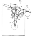
従来の反転部を備えたシート材搬送装置の一例を図12に示す。このシート材搬送装置は、片面に画像が形成されたシート材を反転することにより画像面を下向きにして排出(裏面排出)するものである。これは、画像形成したシート材のページ順を順番どおりに合わせるために行われる。 FIG. 12 shows an example of a sheet material conveying apparatus having a conventional reversing unit. This sheet material conveying apparatus discharges (back surface discharge) with the image surface facing downward by inverting the sheet material on which an image is formed on one side. This is performed in order to align the page order of the image-formed sheet material in order.
即ち、画像が定着器により上面に定着されたシート材は、第1切替え部材24が所定位置まで回転することで搬送路が切替えられ、第1反転パス51に搬送される。そして、シート材は、搬入用ローラ対52によって可撓性部材53Sが設けられたゲート53を通過し、第2反転パス54に搬送される。
That is, the sheet material on which the image is fixed on the upper surface by the fixing device is transported to the
この場合、シート材は、自身の腰の力によって可撓性部材53Sを撓ませゲート53を通過する。なお、可撓性部材53Sは、その一端がゲート53に貼られ、他端が第2反転パス54を構成するガイド板54Gに当接している。
In this case, the sheet material passes through the
そして、第2切替え部材56が所定位置まで回転することで搬送路が切替えられ、シート材は第3反転パス57に搬送される。
Then, the
さらに、シート材は、反転ローラ58によってシート後端が反転ポイントAに到達するまで搬送され、反転センサ55がシート後端を検知してから予め決められた時間経過後に反転ローラ58を停止する。なお、反転ローラ58は正逆転可能な不図示のステッピングモータによって駆動される。
Further, the sheet material is conveyed by the reversing
その後、反転ローラ58を逆回転させる。このとき、シート反転方向先端はゲート53に貼られた可撓性部材53Sによって第1反転パス51への戻りを防止している。シート材は排出用ローラ対59を通過し、外排出ローラ対26により排出用トレイ27上に排出される。これにより、シート材は画像面が下向きになった状態で排出用トレイ27に積載される。
Thereafter, the
近年、画像形成装置の高速化が要望されている。このため、シート材の搬送速度を速くしたり、連続するシート材の間隔を短くしたりすることが行われている。そして、反転部では、シート材を反転させるための時間がかかるため、シート材の搬送速度を増速して高速化を図るようにしているものもある。そこで、図13〜15を用いて連続プリント時の裏面排出において、従来のシート材搬送装置の増速制御の動作について説明する。 In recent years, there has been a demand for speeding up image forming apparatuses. For this reason, increasing the conveyance speed of a sheet material or shortening the space | interval of a continuous sheet material is performed. In the reversing unit, since it takes time to invert the sheet material, there is a reversing unit that increases the conveying speed of the sheet material to increase the speed. Accordingly, the speed increasing control operation of the conventional sheet material conveying apparatus will be described with reference to FIGS.
先ず、シート材である先行紙S1及び後続紙S2は、その後端が定着器を抜けるまでは速度V1で搬送され、必要な定着性を確保する。このとき、先行紙S1及び後続紙S2は、その間隔がλ1で搬送される(図13)。 First, the preceding paper S1 and the succeeding paper S2, which are sheet materials, are conveyed at a speed V1 until the trailing edge passes through the fixing device, and the necessary fixing property is ensured. At this time, the preceding paper S1 and the succeeding paper S2 are conveyed with the interval λ1 (FIG. 13).
次に、先行紙S1の後端がBポイントに到達したとき、搬入用ローラ対52と反転ローラ58のシート材搬送速度をV2に増速し、先行紙S1を第2反転パス54に引込む。そして、先行紙S1の後端がAポイントに到達すると、反転ローラ58を停止する。このとき、先行紙S1と後続紙S2との間隔はλ2に広がる。ここで、BポイントからAポイント間の距離をL1とすると、λ2は次式(1)で表される(図14)。
Next, when the trailing edge of the preceding paper S1 reaches the point B, the sheet material conveying speed of the carry-in
λ2=λ1+V2×(L1/V1)・・・(1) λ2 = λ1 + V2 × (L1 / V1) (1)
その後、反転ローラ58を逆転させて、先行紙S1を速度V2で反転方向へ搬送する。先行紙S1の後端がAポイントを通過以降のタイミングで後続紙S2がAポイントに侵入する。先行紙S1は排出ローラ59、外排出ローラ26によって排出用トレイ27に排出される(図15)。
Thereafter, the reversing
このようなシート材搬送装置では、速度V1が定着器において必要な定着性を確保するための速度で、V1を速くすれば、定着加熱量を増やさなければならないが、定着後にシート材の搬送速度をV2に増速するので、定着加熱量を多くすることが抑えられる。また、シート材をV2に増速してシート材間隔をλ2に拡大したので、第2反転パス54内において先行紙S1と後続紙S2とが衝突しないようにすることができる。なお、定着加熱量を多くすると、シート材に加わる熱量が多くなってシート材に大きなカールが生じたり、十分に乾燥されていない画像が定着器の直後のガイド面で擦れて剥がれたりするなどの弊害がある。
In such a sheet material conveying apparatus, the speed V1 is a speed for securing the necessary fixability in the fixing device. If V1 is increased, the heating amount of fixing must be increased. Is increased to V2, and therefore it is possible to suppress an increase in the fixing heating amount. Further, since the sheet material is accelerated to V2 and the sheet material interval is expanded to λ2, it is possible to prevent the preceding sheet S1 and the succeeding sheet S2 from colliding in the
図16は、1分当たり97枚プリント出力、V1を500mm/s、V2を1000mm/sの高速プリンタを例に増速反転搬送状態を示したダイアグラムである。横軸が時間、縦軸がシート材が反転し排出されるまでのシート搬送パス上の各部品の位置で、二点鎖線で示した横軸がAポイント以降の各部品の位置を示している。 FIG. 16 is a diagram showing the speed-inverted reverse conveyance state, taking as an example a high-speed printer with 97 prints per minute, V1 of 500 mm / s, and V2 of 1000 mm / s. The horizontal axis indicates time, the vertical axis indicates the position of each part on the sheet conveyance path until the sheet material is reversed and discharged, and the horizontal axis indicated by a two-dot chain line indicates the position of each part after the A point. .
さらに、高速化を実現するため、λ2を小さくしたものが特許文献1に開示されている。この特許文献1では、先行紙と後続紙との第2反転パス内での擦れ違いを許している。
Further,
これによって、先行紙後端が反転ポイントAに到達したときの後続紙との間隔λ2を小さくすることができ、結果としてλ1を小さくしている。図17に、この制御方法によって、プリント速度を97枚/分から105枚/分に高速化を図った例を示す。図17より、すり合わせ量が24mmになることが分かる。 As a result, the distance λ2 from the succeeding sheet when the trailing edge of the preceding sheet reaches the reversal point A can be decreased, and as a result, λ1 is decreased. FIG. 17 shows an example in which the printing speed is increased from 97 sheets / minute to 105 sheets / minute by this control method. From FIG. 17, it can be seen that the amount of alignment is 24 mm.
ところで、特許文献1では、後続紙の画像面が先行紙と相対速度V2×2で擦れ違うことになる。また、シート材搬送装置においては、シート材は定着直後であり、画像が十分に乾燥していない場合が多い。このような状態でシート材の画像面が擦られることは画像を著しく劣化させてしまう恐れがある。
By the way, in
本発明の技術的課題は、前記のような事情に鑑みてなされたものであり、その目的は、画像劣化を発生させずに高速化を実現することができる反転部を備えたシート材搬送装置及び画像形成装置を提供することにある。 The technical problem of the present invention has been made in view of the circumstances as described above, and an object thereof is a sheet material conveying apparatus provided with a reversing unit capable of realizing high speed without causing image deterioration. And providing an image forming apparatus.
前記目的を達成するため、本発明に係るシート材搬送装置は、シート材が搬送される第1シート材搬送路と、前記第1シート材搬送路を搬送されてきたシート材を反転搬送する反転ローラと、前記第1シート材搬送路と分岐し前記反転ローラによって反転搬送されるシート材が搬送される第2シート材搬送路と、前記第1シート材搬送路と前記第2シート材搬送路と間に可動に設けられたガイド部材であって、前記第1シート材搬送路を前記反転ローラの方へ向かうシート材を一方の側でガイドし、前記反転ローラによって反転された後に前記第2シート材搬送路を搬送されるシート材を前記一方の側と反対な他方の側でガイドするガイド部材と、を有し、前記第1シート材搬送路を搬送されるシート材の後端が前記ガイド部を通過した後に、前記ガイド部材が前記反転ローラの方へ動くことを特徴とする。 In order to achieve the above object, a sheet material conveying apparatus according to the present invention includes a first sheet material conveying path through which a sheet material is conveyed, and a reversing method that reversely conveys the sheet material conveyed through the first sheet material conveying path. A roller, a second sheet material conveyance path for conveying a sheet material branched from the first sheet material conveyance path and reversed and conveyed by the reversing roller, the first sheet material conveyance path, and the second sheet material conveyance path A guide member movably provided between the first sheet material conveyance path and the second sheet material after guiding the sheet material toward the reversing roller on one side and reversing by the reversing roller. A guide member that guides the sheet material conveyed on the sheet material conveyance path on the other side opposite to the one side, and a rear end of the sheet material conveyed on the first sheet material conveyance path is After passing the guide Wherein the guide member is moved toward the reversing rollers.
本発明によれば、連続プリントにおいて、画像形成時のシート間隔を小さくしつつ、反転部において、シート材の擦れ違いによるが画像の擦れを防止することができる。従って、連続するシート材の高速反転搬送が良好な画像を維持しつつ実現することができる。 According to the present invention, in continuous printing, it is possible to prevent image rubbing while reducing the sheet interval at the time of image formation and depending on the difference in rubbing of the sheet material at the reversal portion. Therefore, high-speed reverse conveyance of continuous sheet materials can be realized while maintaining a good image.
以下、本発明の実施の形態を図面に基づいて詳細に説明する。図1は、本発明の一実施の形態に係るシート材搬送装置をプリンタに適用した例を示す縦断面図である。 Hereinafter, embodiments of the present invention will be described in detail with reference to the drawings. FIG. 1 is a longitudinal sectional view showing an example in which a sheet material conveying apparatus according to an embodiment of the present invention is applied to a printer.
図1において、1はプリンタ本体であり、その上部には、原稿5を読み取り部2に連続的に搬送可能な自動原稿送り装置3が設けられている。
In FIG. 1,
201は固定して設けられた透明ガラス板からなる原稿台であり、自動原稿送り装置によって原稿5を原稿台の所定の位置に画像面を下向きにして固定する。原稿台201の下側には原稿5を照明するランプ202と、照明した原稿5の光像を画像メモリー部203に導くための反射ミラー204、205、206及び結像レンズ11とからなる光学系が設けられている。なお、ランプ202及び反射ミラー204、205、206は矢印a方向に所定の速度で移動して原稿5を走査する。
画像形成部は、感光ドラム12と、この感光ドラム12の表面に均一な帯電を施すための帯電器13とを有している。さらに、帯電器13により帯電された感光ドラム12の表面にスキャナ8から照射される光像により形成された静電潜像を現像してシート材Sに転写すべきトナー像を形成する現像器14を有する。また、画像形成部は、転写帯電器19と分離帯電器20とクリーナ15とを備えている。
The image forming unit includes a
転写帯電器19は感光ドラム12の表面に現像されたトナー像をシート材Sに転写する。分離帯電器20は感光ドラム12からトナー像が転写されたシート材Sを分離する。また、クリーナ15はシート材Sにトナー像が転写された後、感光ドラム12に残留したトナーを除去する。
The
給送トレイ32上のシート材Sの片面にプリントし、画像面を表向きに排出する場合、不図示のスタートボタンを押すと、シート材Sが給送ローラ36a、36b、36cにより送り出される。そして、搬送ローラ対37、38で搬送されて、レジストローラ対45でシートSの斜送を矯正し、所定のタイミングで画像形成部の転写位置に搬送される。
When printing is performed on one side of the sheet material S on the feeding
画像形成部の下流側にはトナー像が転写されたシートSを搬送するためのベルト搬送部21と、ベルト搬送部により搬送されるシート材S上の像を永久画像として定着するための定着器22が設けられている。
On the downstream side of the image forming unit, a
定着器22で像が定着されたシート材Sは内排出ローラ対23を通過し、第1切替え部材24によってストレイト排出搬送路25に導かれ、外排出ローラ対26によってプリンタ本体1から排出される。プリンタ本体1の外側には排出トレイ27が設けられており、外排出ローラ対26によって排出されたシート材Sを受取りコピーが完了する。
The sheet material S on which the image is fixed by the fixing
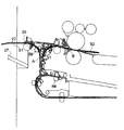
次に、シート材搬送装置の構成を説明する。ここで、図2にシート材搬送装置の断面図、図3、4にシート材搬送装置の斜視図を示す。 Next, the configuration of the sheet material conveying apparatus will be described. Here, FIG. 2 is a sectional view of the sheet material conveying apparatus, and FIGS. 3 and 4 are perspective views of the sheet material conveying apparatus.
図2において、第1シート材搬送路51を形成している反転中右ガイド62と第2シート材搬送路54を形成している反転中左ガイド64の内側に、複数のベルト71が固定軸73、75及び可動軸(ガイド部材)72、74に掛け回されている。このベルト71は、可撓性材料、例えばPETフィルム等の材料からなる。そして、第2シート材搬送路54は第1シート材搬送路51の下流側で接続している。可動軸74は第1シート材搬送路51と第2シート材搬送路54との接続部で移動可能となっている。
In FIG. 2, a plurality of
可動軸74は、図3、4に示すように、フレーム81F、81R間に配置され、その両端が軸受74Bによって支持されている。また、この可動軸74には複数の回転部材であるコロ74Cが同軸上に配設されている。これら複数のコロ74Cは、ベルト71の幅寸法より1mm程度大きい外形を有し、可動軸74の軸方向にベルト71と交互に並列している。そして、可動軸74はフレーム81F、81Rに設けた逆「く」の字形状の溝81FH1、81RH1に沿って軸受74Bを介して矢印A方向へ移動可能になっている。
As shown in FIGS. 3 and 4, the
また、可動軸72も同様にフレーム81F、81Rに設けた溝81FH2、81RH2に沿って軸受71Bを介して矢印B方向へ移動可能になっている。可動軸72は引っ張りバネ76F、76Rによって矢印Bと反対方向へ付勢されている。引っ張りバネ76F、76Rは、その一端がフレーム81F、81Rに設けたバネ掛け軸81Pに支持され、他端が可動軸72に掛けられている。
Similarly, the
可動軸74はアーム82によって駆動ギア83に連結され、駆動ギア83には係合軸83Bが一体成形されている。アーム82は可動軸74及び係合軸83Bに回動可能に支持されている。また、駆動ギア83は不図示のステッピングモータによって回転角度を高精度に制御可能となっている。
The
以下に、図5〜10を用いてシート材反転搬送時の可動軸72、74の動作位置について説明する。先ず、通常またはプリント数が1枚の場合のプリント中、可動軸72、74は図5、6の位置にある。リンクギア83の位相角度を検知する不図示のセンサによってこの位置をホームポジションとして設定する。
Hereinafter, the operation positions of the
シートS1が正転方向の移動(引き込み)を停止してから逆転方向の搬送(反転)を開始する以前に、可動軸72、74を図7、8の位置に移動する。これによってシートS1が搬入用シート搬送路51に戻ることを防止する。つまり、可動軸74が戻り防止手段として作用する。
The
その後、先行紙先端が合流位置を通過してから図5、6で示す位置に戻す。リンクギア83は可動軸74が所定の位置に停止するために、不図示のステッピングモータによってホームポジションから予め決められたステップ角を回転する。
Thereafter, the leading edge of the preceding paper passes through the joining position and then returns to the position shown in FIGS. The
そして、先行紙S1と後続紙S2が擦れ違いを発生するタイミングで可動軸74を図9、10の位置に移動する。反転中の先行紙の後端が合流位置Aを通過してから、後続紙S2が引き込みを終了する以前に図5、6で示す位置に戻す。これらの移動も不図示のステッピングモータによって予め決められたステップ角を回転して行う。
Then, the
次に、図11に示すフローチャートを用いてシート材搬送装置の制御方法について説明する。 Next, a control method of the sheet material conveying apparatus will be described using the flowchart shown in FIG.
Nx枚目のレジストローラ対45による搬送が開始されて以降の制御方法について説明する(ステップS1)。先ず、内排出センサがNx枚目のシート材先端を検知したタイミングをT=T0とする(ステップS2)。Nx枚目のシート材先端が合流位置に到達する以前で十分余裕のある時間(T=T1)にリンクギア、可動軸74の位置を図5の位置に正確に固定する(ステップS3)。
A control method after the conveyance by the Nx-th
Nx枚目が最終のプリントであれば、可動軸72、74はホームポジションのままで終了する。後続プリントがある場合に次の制御に移行する(ステップS4)。Nx枚目のシート材先端が合流位置に到達する以前で十分余裕のある時間(T=T2、T2>T1)になったら次の制御に移行する(ステップS5)。
If the Nxth print is the final print, the
不図示の可動軸移動用ステッピングモータを駆動して可動軸72、74を図9で示す位置に移動する。このとき先行紙S1(Nx-1枚目)と後続紙S2(Nx枚目)が擦れ違わないようになる(ステップS6)。
A movable shaft moving stepping motor (not shown) is driven to move the
Nx枚目のシート材Sが引き込み動作を停止する前の予め決められた時間(T=T3)になったら次の制御に移行する(ステップS7)。Nx枚目のシート材先端が確実に搬出用シート搬送路59に導かれるように移動軸74を図5の位置に戻す(ステップS8)。
When the predetermined time (T = T3) before the Nxth sheet material S stops the pull-in operation, the process proceeds to the next control (step S7). The moving
Nx枚目の引き込み動作が終了したら、次の制御に移行する(ステップS9)。移動軸74を図7の位置に移動する。シート材Sの搬入用搬送路への戻りを確実に防止する(ステップS10)。搬出用ローラ57および不図示の反転ローラによって反転を開始する(ステップS11)。Nx枚目のシート材先端が合流位置を過ぎた一定時間後(T=T4)に次の制御に移行する(ステップS12)。可動軸74を図5の位置に戻す(ステップS13)。以降、ステップS2に戻る。
When the Nxth drawing operation is completed, the process proceeds to the next control (step S9). The moving
このように、本実施形態では、可動軸74を移動させることで、ベルト71によって第2シート搬送路54を2分割する。これによって、画像形成時に連続搬送されるシート材Sの間隔を小さくしつつ、第2シート搬送路54内での先行紙S1と後続紙S2との擦れ違いを防止することができる。
Thus, in the present embodiment, the second
また、可動軸74と同軸状のコロ74Cを設けたことで、シート材Sの画像面の擦れを防止することができる。
Further, by providing the
また、可動軸74及びベルト71が、シート材Sの第1シート材搬送路51への戻りを防止する位置に移動するので、剛性の小さなシート材Sであっても戻りが確実に防止される。
Further, since the
以上、本発明の実施の形態について詳述したが、本発明は、前記実施の形態記載に限定されるものではなく、本発明の特許請求の範囲に記載されている発明の精神を逸脱しない範囲で、種々の変更ができるものである。 The embodiment of the present invention has been described in detail above, but the present invention is not limited to the above-described embodiment, and the scope does not depart from the spirit of the invention described in the claims of the present invention. Thus, various changes can be made.
たとえば、本実施の形態では、第2シート材搬送路54の分割手段に可動軸74及びベルト71を用いたが、これに限定されず、板金性のガイド部材を移動可能に構成しても同様の効果が期待できる。
For example, in the present embodiment, the
51 第1シート材搬送路
54 第2シート材搬送路
71 ベルト(可撓性フィルム)
72、74 可動軸
74C コロ
73、75 固定軸
76R、76F 可動軸付勢バネ
77 内排出センサ
81F、81R フレーム
82 アーム
83 リンクギア
S シート材
S1 先行紙
S2 後続紙
51 1st sheet material conveyance path
54 Second sheet material conveyance path
71 Belt (flexible film)
72, 74 Movable axis
74C roller
73, 75 Fixed shaft
76R, 76F Movable shaft bias spring
77 Internal discharge sensor
81F, 81R frame
82 arms
83 Link gear S Sheet material S1 Predecessor paper S2 Subsequent paper
Claims (7)
前記第1シート材搬送路を搬送されてきたシート材を反転搬送する反転ローラと、
前記第1シート材搬送路と分岐し前記反転ローラによって反転搬送されるシート材が搬送される第2シート材搬送路と、
前記第1シート材搬送路と前記第2シート材搬送路と間に可動に設けられたガイド部材であって、前記第1シート材搬送路を前記反転ローラの方へ向かうシート材を一方の側でガイドし、前記反転ローラによって反転された後に前記第2シート材搬送路を搬送されるシート材を前記一方の側と反対な他方の側でガイドするガイド部材と、を有し、
前記第1シート材搬送路を搬送されるシート材の後端が前記ガイド部を通過した後に、前記ガイド部材が前記反転ローラの方へ動くことを特徴とするシート材搬送装置。 A first sheet material conveyance path through which the sheet material is conveyed;
A reversing roller for reversing and conveying the sheet material that has been conveyed through the first sheet material conveying path;
A second sheet material conveyance path through which the sheet material branched from the first sheet material conveyance path and conveyed by the reversing roller is conveyed;
A guide member movably provided between the first sheet material conveyance path and the second sheet material conveyance path, wherein the sheet material traveling toward the reverse roller on the first sheet material conveyance path on one side And a guide member for guiding the sheet material conveyed on the second sheet material conveyance path after being reversed by the reversing roller on the other side opposite to the one side,
The sheet material conveying apparatus, wherein the guide member moves toward the reversing roller after a rear end of the sheet material conveyed on the first sheet material conveying path passes through the guide portion.
Priority Applications (2)
| Application Number | Priority Date | Filing Date | Title |
|---|---|---|---|
| JP2008149456A JP5322505B2 (en) | 2008-06-06 | 2008-06-06 | Sheet material conveying apparatus and image forming apparatus |
| US12/479,296 US8087665B2 (en) | 2008-06-06 | 2009-06-05 | Sheet conveying apparatus and image forming apparatus with movable unit at a branch position |
Applications Claiming Priority (1)
| Application Number | Priority Date | Filing Date | Title |
|---|---|---|---|
| JP2008149456A JP5322505B2 (en) | 2008-06-06 | 2008-06-06 | Sheet material conveying apparatus and image forming apparatus |
Publications (3)
| Publication Number | Publication Date |
|---|---|
| JP2009292616A JP2009292616A (en) | 2009-12-17 |
| JP2009292616A5 JP2009292616A5 (en) | 2011-07-21 |
| JP5322505B2 true JP5322505B2 (en) | 2013-10-23 |
Family
ID=41399589
Family Applications (1)
| Application Number | Title | Priority Date | Filing Date |
|---|---|---|---|
| JP2008149456A Expired - Fee Related JP5322505B2 (en) | 2008-06-06 | 2008-06-06 | Sheet material conveying apparatus and image forming apparatus |
Country Status (2)
| Country | Link |
|---|---|
| US (1) | US8087665B2 (en) |
| JP (1) | JP5322505B2 (en) |
Families Citing this family (3)
| Publication number | Priority date | Publication date | Assignee | Title |
|---|---|---|---|---|
| JP6075318B2 (en) | 2014-03-28 | 2017-02-08 | ブラザー工業株式会社 | Image forming apparatus |
| JP6128035B2 (en) * | 2014-03-28 | 2017-05-17 | ブラザー工業株式会社 | Image forming apparatus |
| JP6775950B2 (en) * | 2015-12-28 | 2020-10-28 | キヤノン株式会社 | Sheet transfer device and image forming device |
Family Cites Families (4)
| Publication number | Priority date | Publication date | Assignee | Title |
|---|---|---|---|---|
| JPH09278251A (en) * | 1996-04-15 | 1997-10-28 | Canon Inc | Sheet switchback device and image forming device |
| US6478490B2 (en) * | 2000-12-01 | 2002-11-12 | Hewlett-Packard Co. | Printer media transport apparatus and method |
| US6460847B1 (en) * | 2001-06-18 | 2002-10-08 | Hewlett-Packard Company | Sheet flow direction changing mechanism |
| JP4836881B2 (en) * | 2007-06-26 | 2011-12-14 | シャープ株式会社 | Sheet conveying path structure and image forming apparatus having the same |
-
2008
- 2008-06-06 JP JP2008149456A patent/JP5322505B2/en not_active Expired - Fee Related
-
2009
- 2009-06-05 US US12/479,296 patent/US8087665B2/en not_active Expired - Fee Related
Also Published As
| Publication number | Publication date |
|---|---|
| US8087665B2 (en) | 2012-01-03 |
| JP2009292616A (en) | 2009-12-17 |
| US20090302524A1 (en) | 2009-12-10 |
Similar Documents
| Publication | Publication Date | Title |
|---|---|---|
| CN108732888B (en) | Sheet conveying apparatus and image forming apparatus | |
| JP2009196803A (en) | Paper conveying device | |
| US8577269B2 (en) | Image forming apparatus | |
| JP5322505B2 (en) | Sheet material conveying apparatus and image forming apparatus | |
| US10564584B2 (en) | Sheet-conveying device, image-forming apparatus, and image-reading apparatus | |
| JP5672993B2 (en) | Image forming apparatus | |
| JP4439461B2 (en) | Image forming apparatus and switchback transport mechanism | |
| US10087029B2 (en) | Sheet conveyance device, image forming apparatus, and image reading apparatus | |
| US7588248B2 (en) | Sheet conveying device and image forming apparatus | |
| JP5168068B2 (en) | Reversed duplex unit and image forming apparatus | |
| JP5640669B2 (en) | Image forming apparatus | |
| JP2007045541A (en) | Inversion device, image formation device, electrophotograph copier, facsimile, printer and scanner | |
| JP2008120561A (en) | Sheet conveyor, image forming device and image reader | |
| JP3947899B2 (en) | Sheet transport device | |
| JP2019064809A (en) | Sheet conveying device, image forming device, and image reading device | |
| WO2017170116A1 (en) | Sheet conveying device, image forming device, and image scanning device | |
| JP2010202388A (en) | Paper conveying device and image forming device | |
| JP3915524B2 (en) | Image forming apparatus | |
| JP2014172685A (en) | Paper path switching device and image forming device | |
| JP2001206587A (en) | Sheet feeder and image forming device having the same | |
| JP2019011162A (en) | Sheet conveying device and image forming apparatus | |
| JP2003146515A (en) | Sheet material conveyance device and image formation device | |
| JP2019001645A (en) | Sheet conveyance device and image formation apparatus | |
| JP2012185456A (en) | Transfer device and image forming apparatus | |
| JP2014076876A (en) | Image formation device |
Legal Events
| Date | Code | Title | Description |
|---|---|---|---|
| A521 | Request for written amendment filed |
Free format text: JAPANESE INTERMEDIATE CODE: A523 Effective date: 20110603 |
|
| A621 | Written request for application examination |
Free format text: JAPANESE INTERMEDIATE CODE: A621 Effective date: 20110603 |
|
| A977 | Report on retrieval |
Free format text: JAPANESE INTERMEDIATE CODE: A971007 Effective date: 20120829 |
|
| A131 | Notification of reasons for refusal |
Free format text: JAPANESE INTERMEDIATE CODE: A131 Effective date: 20120904 |
|
| A521 | Request for written amendment filed |
Free format text: JAPANESE INTERMEDIATE CODE: A523 Effective date: 20121105 |
|
| A131 | Notification of reasons for refusal |
Free format text: JAPANESE INTERMEDIATE CODE: A131 Effective date: 20130108 |
|
| A521 | Request for written amendment filed |
Free format text: JAPANESE INTERMEDIATE CODE: A523 Effective date: 20130307 |
|
| TRDD | Decision of grant or rejection written | ||
| A01 | Written decision to grant a patent or to grant a registration (utility model) |
Free format text: JAPANESE INTERMEDIATE CODE: A01 Effective date: 20130618 |
|
| A61 | First payment of annual fees (during grant procedure) |
Free format text: JAPANESE INTERMEDIATE CODE: A61 Effective date: 20130716 |
|
| LAPS | Cancellation because of no payment of annual fees |