JP3947899B2 - Sheet transport device - Google Patents
Sheet transport device Download PDFInfo
- Publication number
- JP3947899B2 JP3947899B2 JP2000268229A JP2000268229A JP3947899B2 JP 3947899 B2 JP3947899 B2 JP 3947899B2 JP 2000268229 A JP2000268229 A JP 2000268229A JP 2000268229 A JP2000268229 A JP 2000268229A JP 3947899 B2 JP3947899 B2 JP 3947899B2
- Authority
- JP
- Japan
- Prior art keywords
- sheet
- conveying
- member pair
- conveying member
- nipped
- Prior art date
- Legal status (The legal status is an assumption and is not a legal conclusion. Google has not performed a legal analysis and makes no representation as to the accuracy of the status listed.)
- Expired - Fee Related
Links
Images


Landscapes
- Controlling Sheets Or Webs (AREA)
- Delivering By Means Of Belts And Rollers (AREA)
- Registering Or Overturning Sheets (AREA)
Description
【0001】
【発明の属する技術分野】
この発明は、シートを搬送するシート搬送装置に係り、特に、搬送中にシートの位置合わせを行うタイプのシート搬送装置の改良に関する。
【0002】
【従来の技術】
一般に、電子写真方式などを利用した画像形成装置としては、例えば画像信号に応じた静電潜像を感光体ドラム等の潜像担持体上に形成し、これを現像して得られたトナー像(画像)を直接若しくは中間転写体を介して用紙などのシートに転写する方式が採用されている。
そして、この種の画像形成装置では、シート上に画像を正確に転写するために、所定の基準位置にシートを位置合わせすることが通常行われており、この位置合わせ方式としては、シートの先端(リード)を位置合わせした後に転写部位に送出するリードレジストレーション方式や、シートの側端(サイド)を所定のサイド基準位置に位置合わせした後に転写部位に送出するサイドレジストレーション方式などがある。
【0003】
ここで、リードレジストレーション方式はシートが斜行し易いため、シートの表裏面における画像の位置ずれを生じ易いが、サイドレジストレーション方式ではシートが常に所定のサイド基準位置に位置合わせされるため、前記シートの表裏面における画像の位置ずれを低減できる点で好ましい。
そして、このようなサイドレジストレーション方式のシート搬送装置の一例としては、レジロールなどをシート搬送方向と直交する方向に移動自在に配設すると共に、レジロールの近傍にシートの端部を検知するセンサを配設し、このセンサの検知結果に基づいてレジロールの移動量(サイドシフト量)を制御して、シートを所定のサイド基準位置に位置合わせする技術が既に知られている(例えば特開昭61−249063号、特開平2−198952号公報参照)。
【0004】
【発明が解決しようとする課題】
ところで、上述したサイドレジストレーション方式のシート搬送装置においても、シート搬送中にシートの姿勢がばらついてサイドスキューを生じてしまうことがある。
すると、上述したシート搬送装置では、レジロールにシートがニップされた直後、すなわち、シートの先端側の側端がセンサを通過しているときにサイドシフト動作が開始されるため、シートがスキューした場合には、本来サイドシフトセンサが検知を行うべきタイミングと実際にサイドシフトセンサが検知を行うタイミングとがずれてしまい、サイドレジの整合に影響が生じ、サイドシフト量の過不足を招いてしまう。
【0005】
また、シートの先端若しくは後端の位置を検知するセンサを設け、このセンサの検知結果に基づいてシート搬送速度の加減速やタイミング調整を行うようにしたリードレジストレーション方式のシート搬送装置が知られているが(例えば特開平3−46946号公報参照)、このようなシート搬送装置においても、センサの配設位置によっては、シート搬送中にシートの姿勢がばらついてリードスキューを生じた場合に、リードレジ整合に影響が生じることとなってしまう。
【0006】
本発明は、以上の技術的課題を解決するためになされたものであって、シート搬送時に少なからず起こるシートスキューの影響を最小限にすることで、主としてシートのサイドレジストレーション整合を精度良く行うことのできるシート搬送装置を提供するものである。
【0007】
【課題を解決するための手段】
すなわち、本発明は、図1(a)(b)に示すように、複数の異なるサイズのシートSをニップして搬送する搬送部材対1と、前記搬送部材対1よりもシート搬送方向上流側に位置し且つ予め設定されたシートSの側端整合初期位置に向けてシートSをニップして斜行搬送するニップリリース可能な斜行搬送部材対と、前記搬送部材対1よりもシート搬送方向上流側に位置し且つ前記搬送部材対1にニップされたシートSの側端を検知する側端検知手段2と、前記搬送部材対1にシートSがニップされた状態で、当該搬送部材対1をシートSの搬送方向と直交する方向に変位させる変位手段3と、前記搬送部材対1にシートSの先端部がニップされる前にシートニップ状態の斜行搬送部材対をリリースし、前記搬送部材対1にシートSの先端部がニップされた状態にて前記側端検知手段2による検知結果に基づいて、前記変位手段3による前記搬送部材対1の変位量を制御する制御手段4とを備え、前記側端検知手段2が、前記搬送部材対1にシートSの先端部がニップされた状態にて前記制御手段4による変位制御開始時の使用シートSの搬送方向中央部に対応する位置に配置されることを特徴とする。尚、図1(b)は(a)の平面説明図である。
【0008】
このような技術的手段において、搬送部材対1としては、例えば駆動可能なロール状部材(ドライブレジロール)を含み、これに従動ロール(アイドルレジロール)を圧接配置することで、シートSをニップして搬送するものが代表例として挙げられるが、これに限られるものではなく、更にシートSを一時停止させるためのゲート部材を別途付加するものなど適宜選定して差し支えなく、また、その形状もロール状のものに限られない。
【0009】
また、側端検知手段2は、前記搬送部材対1にニップされた状態のシートSの側端位置を検知するものであれば、その検知方式については種々の方式より適宜選定して差し支えない。
【0010】
更に、変位手段3は、前記搬送部材対1にシートSがニップされた状態で、当該搬送部材対1をシートSの搬送方向と直交する方向に変位させる機能を有するものであればよく、更にまた、制御手段4は、前記側端検知手段2による検知結果に基づいて、前記変位手段3による前記搬送部材対1の変位量を制御するものであればよい。
【0011】
そして、本発明においては、前記側端検知手段2が、前記制御手段4による変位制御開始時のシートSの搬送方向中央部に対応する位置に配置される。
この側端検知手段2の配設手法としては、例えば、複数の異なるサイズのシートに適宜対応させるという観点からすれば、シート搬送方向に沿って移動自在に配設する手法や、また、シート搬送方向に沿って複数配設する手法を採用することが好ましい。また、側端検知手段2を少なくとも一つの定型サイズのシートの搬送方向中央部に対応する位置に固定配設するようにしてもよい。そして、このような態様にあっては、最も使用頻度の高いサイズのシートの搬送方向中央部に対応する位置に側端検知手段2を配設するとよい。
【0012】
また、本発明は別の観点から捉えれば、図1(a)(b)に示すように、複数の異なるサイズのシートSをニップして搬送する搬送部材対1と、前記搬送部材対1よりもシート搬送方向上流側に位置し且つ予め設定されたシートSの側端整合初期位置に向けてシートSをニップして斜行搬送するニップリリース可能な斜行搬送部材対と、前記搬送部材対1よりもシート搬送方向上流側に位置し且つ前記搬送部材対1にニップされたシートSの側端を検知する側端検知手段2と、前記搬送部材対1にシートSがニップされた状態で、当該搬送部材対1をシートSの搬送方向と直交する方向に変位させる変位手段3と、前記搬送部材対1にシートSの先端部がニップされる前にシートニップ状態の斜行搬送部材対をリリースし、前記搬送部材対1にシートSの先端部がニップされた状態にて前記側端検知手段2による検知結果に基づいて、前記変位手段3による前記搬送部材対1の変位量を制御する制御手段4とを備え、前記制御手段4が、前記搬送部材対1にシートSの先端部がニップされた状態にて搬送される使用シートSの搬送方向中央部が前記側端検知手段2に到達した時点で、前記搬送部材対1の変位制御を開始するものということができる。
【0013】
更に、本発明に関連する参考発明としては、複数の異なるサイズのシートをニップして搬送する搬送部材対と、前記搬送部材対よりもシート搬送方向上流側に位置し且つ予め設定されたシートの側端整合初期位置に向けてシートをニップして斜行搬送するニップリリース可能な斜行搬送部材対と、前記搬送部材対よりもシート搬送方向上流側に位置し且つ前記搬送部材対にニップされたシートの側端を検知する側端検知手段と、前記側端検知手段のシート搬送方向上流側または下流側に配設され、前記側端検知手段と同じ側のシートの側端を検知する第二側端検知手段と、前記搬送部材対にシートがニップされた状態で、当該搬送部材対をシートの搬送方向と直交する方向に変位させる変位手段と、前記搬送部材対にシートの先端部がニップされる前にシートニップ状態の斜行搬送部材対をリリースし、前記搬送部材対にシートの先端部がニップされた状態にて前記側端検知手段及び前記第二側端検知手段による検知結果に基づいて、前記変位手段による前記搬送部材対の変位量を制御する制御手段とを備え、前記制御手段は、前記搬送部材対にシートの先端部がニップされた状態にて前記側端検知手段及び前記第二側端検知手段による検知動作を開始し前記搬送部材対の変位制御を開始することを特徴とするものが挙げられる。
【0014】
このような技術的手段において、搬送部材対、側端検知手段、変位手段及び制御手段については、上述したものと同様のものより適宜選定して差し支えない。
そして、第二側端検知手段については、前記側端検知手段の上流側または下流側に配設され、前記側端検知手段と同じ側のシートの側端を検知するものであれば、当該側端検知手段と同様のものから適宜選定して差し支えない。
更に、補正手段については、前記側端検知手段及び前記第二側端検知手段の検知結果に基づいてシートのスキュー量を判断し、これに応じて前記変位手段による前記搬送部材対の変位量を補正するものであれば適宜選定して差し支えない。
【0015】
また、本発明において、更にシートのリードレジストレーションを考慮した態様としては、前記搬送部材対にニップされたシートの先端若しくは後端を検知する端部検知手段を備え、前記端部検知手段が、搬送されるシートの搬送方向に直交する方向中央部に対応する位置に配置されるものが挙げられる。
【0016】
このような技術的手段において、搬送部材対は、上述したものと同様のものより適宜選定して差し支えない。
また、端部検知手段は、前記搬送部材対にニップされたシートの先端若しくは後端位置を検知するものであれば、その検知方式については種々の方式より適宜選定して差し支えない。
【0017】
そして、このような態様にあっては、前記端部検知手段は、搬送されるシートの搬送方向に直交する方向中央部に対応する位置に配置される。
この端部検知手段の配設手法としては、例えば複数の異なるサイズのシートに適宜対応させるという観点からすれば、シート搬送方向に直交する方向に沿って移動自在に配設する手法や、シート搬送方向に直交する方向に沿って複数配設する手法を採用することが好ましい。
【0018】
【発明の実施の形態】
以下、添付図面に示す実施の形態に基づいてこの発明を詳細に説明する。
◎実施の形態1
図2は、本発明が適用された本発明に係るシート搬送装置が組み込まれた画像形成装置の実施の形態1を示す説明図である。
同図において、本実施の形態に係る画像形成装置は、所謂タンデム型の中間転写方式を採用した画像形成装置であり、作像モジュール30が収容された画像形成ユニット21と、この画像形成ユニット21に並列配置されてシートKを画像形成ユニット21に供給するシート供給ユニット22と、前記画像形成ユニット21に並列配置されて画像形成ユニット21にて画像形成されたシートKに対して後処理を施す後処理ユニット23とを備えたものである。
【0019】
本実施の形態において、画像形成ユニット21は、例えば電子写真方式にて各色成分トナー像(例えばイエロ(Y)、マゼンタ(M)、シアン(C)、ブラック(K))が形成される作像モジュール30を収容したものであり、この作像モジュール30は、各色成分トナー像を形成担持する感光体ドラム31(具体的には31Y、31M、31C、31K)を並列配置し、各感光体ドラム31で形成された各色成分トナー像を中間転写ベルト40に順次一次転写させ、二次転写ロール50にシート供給ユニット22から供給されるシートKに中間転写ベルト40上の各色成分トナー像を二次転写させ、定着器60に導くようにしたものである。
【0020】
本実施の形態において、各感光体ドラム31の周囲には、感光体ドラム31を帯電する一様帯電器(図示せず)、感光体ドラム31上に静電潜像を書き込むレーザ露光器33、各色成分トナーが収容されて感光体ドラム31上の静電潜像を可視像化する現像器34、感光体ドラム31上の各色成分トナー像を中間転写ベルト40に転写せしめる一次転写ロール35及び感光体ドラム31上の残留トナーなどを除去するクリーナ36などの電子写真用デバイスが順次配設されている。
また、中間転写ベルト40は複数(本例では5つ)の張架ロール41〜45に張架されて循環搬送されるものであり、例えば張架ロール41を駆動ロールとすると共に、他の張架ロール42〜45を従動ロールとし、更に張架ロール42〜45のうちの任意の張架ロール、例えば張架ロール43を中間転写ベルト40に張力が付与せしめられるテンションロールとして機能させるようにしたものである。
そして、本実施の形態では、中間転写ベルト40の張架ロール44に対向する部位が二次転写部位として設定されており、この中間転写ベルト40の二次転写部位表面側には二次転写ロール50が接触配置され、この二次転写ロール50とこれに対向する張架ロール44(バックアップロールとして機能)との間に転写バイアスが印加されるようになっている。
【0021】
更に、本実施の形態において、シート供給ユニット22は、多段(本例では3段)のシート供給トレイ71〜73を有し、シート供給トレイ71,72にはサイズの異なる普通紙からなるシートKを収容する一方、最下段の大容量シート供給トレイ73には、塗工紙、厚紙等の曲げ剛性の高いシートKを含む特殊シートを収容するようにしたものである。
特に、本実施の形態では、シート供給トレイ71,72は画像形成ユニット21の反対側にフィードロール74,75を有し、シート供給トレイ73は画像形成ユニット21側にフィードロール76を有している。
そして、シート供給トレイ71,72からのシート搬送路は、シート供給ユニット22の画像形成ユニット21の反対側側方から上方へ向かい、上方スペースを利用して画像形成ユニット21側へと向かった後、下方へと向かう迂回搬送路77として構成されている。
一方、シート供給トレイ73からのシート搬送路は、画像形成ユニット21側へ略直線状に延びる直結搬送路78として構成されており、この直結搬送路78及び前記迂回搬送路77は合流搬送路79に連通接続され、シートKを送出口80から画像形成ユニット21側へ送出するようになっている。
【0022】
更に、シート供給ユニット22の迂回搬送路77、直結搬送路78及び合流搬送路79には、対構成の複数の搬送ロール81が所定間隔毎に設けられている。特に、シート供給ユニット22のユニットケース220のうち、画像形成ユニット21と反対側に位置する部分には、迂回搬送路77に面して開閉するカバー100が設けられている。
このカバー100は、例えばユニットケース220の奥側を回転支点として回動すると共に、対構成の搬送ロール81(81a、81b)のうち従動ロール81bを回動自在保持するものであり、解放時において搬送ロール81の駆動ロール81aと従動ロール81bとを分離配置するものである。
また、本実施の形態では、画像形成ユニット21の反対側に向かって水平方向に延びる連結搬送路101が形成されており、この連結搬送路101は、例えばシート供給ユニット22に隣接して別のシート供給ユニット(図示せず)を配設した態様において、別のシート供給ユニットから供給されるシートKを受け入れ、迂回搬送路77へと案内する搬送路として働いたり、あるいは、シート供給ユニット22の手差しによるシートKの挿入部として働くようになっている。
【0023】
更に、本実施の形態では、シート供給ユニット22の上方に、画像読取ユニット24及びユーザー操作部25が配設されている。
尚、画像読取ユニット24は、原稿台に置かれた原稿の画像を光学的に読み取るものであり、例えば光源、反射ミラー、結像レンズ、CCDセンサ等から構成される。
【0024】
更にまた、本実施の形態において、後処理ユニット23は、画像形成ユニット21のユニットケース210に開設されたシートKの排出口211に対応したユニットケース230位置に入口開口231を有し、一方、画像形成ユニット21の反対側のユニットケース230位置に出口開口232を開設している。
本例では、入口開口231は後処理ユニット23の下半部の所定位置に設けられ、一方、出口開口232は後処理ユニット23の上半部の所定位置に設けられ、出口開口232に対応したユニットケース230にはシート排出トレイ233が取り付けられている。
更に、入口開口231と出口開口232との間には斜め方向に向かう傾斜搬送路234が設けられており、この傾斜搬送路234は途中で二つに分岐し、各分岐搬送路にはアップカール矯正用、ダウンカール矯正用のカール矯正装置235,236が配設されている。
【0025】
また、画像形成ユニット21内のシート搬送路は、シート供給ユニット22から供給されたシートKを二次転写部位に導いた後に、定着器60を通過させて後処理ユニット23側へ排出する経路以外に、定着器60から送り出されたシートKを反転して再度二次転写部位に戻す経路を備えている。
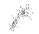
特に、本実施の形態では、画像形成ユニット21内のシート搬送ユニット90として、二次転写部位の上流側に配置された複数(例えば3つ)の対構成からなる斜行ロール82と、二次転写部位の手前に配置された搬送部材対としての対構成のレジストレーションロール(レジロール)83とを備えている。
また、二次転写部位通過後のシートKは、例えば搬送ベルト84にて定着器60へと搬送される。
【0026】
更に、本実施の形態で用いられるシート戻し機構としては、定着器60から送り出されたシートKをループ状の戻し経路85に沿って適宜数の搬送ロール86にて搬送するものであるが、戻し経路85の途中に反転部(本例では後処理ユニット23内の下部スペースを利用して構成)87を設け、この反転部87を介してシートKを反転させるようにしたものである。
尚、戻し経路85の一部はシート供給ユニット22内のスペースを利用し、合流搬送路79に連通接続されるようになっている。
【0027】
次に、上述したシート搬送ユニット90について更に詳細に説明する。
本実施の形態において、シート搬送ユニット90は、図5に示すように、対構成からなるレジロール83及びその上流側に配設される複数(本例では3つ)の斜行ロール82がユニット化されたものである。
そして、シート搬送ユニット90は、その上下にシートKを案内搬送するガイドシュート901,902を有すると共に、シート搬送方向に直交する方向の一方に板状の固定サイドガイド903を立設し、この固定サイドガイド903の内面をシートKの側端が初期的に揃えられるサイド初期位置SIPとして設定するようにしたものである。
【0028】
そして、斜行ロール82は、図3〜図5に示すように、シートKの搬送方向に対し先端側が前記固定サイドガイド903に向かって僅かに傾斜し、且つ、パルスモータからなる駆動モータ51にて駆動せしめられるドライブ斜行ロール821と、これに圧接配置されて追従回転するアイドル斜行ロール822とで構成されており、ニップリリース(N/R:Nip/Release)モータ52〜54にて例えばアイドル斜行ロール822がドライブ斜行ロール821に対しニップ若しくはリリースされるようになっている。
また、レジロール83は、図3〜図7に示すように、例えばパルスモータにて構成される駆動モータ(レジモータ)55にて回転駆動せしめられるドライブレジロール831と、このドライブレジロール831に圧接配置されて追従回転するアイドルレジロール832とで構成されており、ニップリリースモータ56にて例えばアイドルレジロール832がドライブレジロール831に対しニップ若しくはリリースされるようになっている。
【0029】
更に、レジロール83(831,832)は、図3〜図7に示すように、シート搬送ユニット90のユニットフレーム900に軸方向に対して移動自在に回転支承されており、ドライブレジロール831の支承軸一端にはカップリング57を介してサイドシフト機構58が設けられている。
このサイドシフト機構58は、カップリング57に連結されるシャフト581にラック582を取り付け、このラック582にピニオンギア583を噛合させ、前記ピニオンギア583をサイドシフトモータ584にて所定量回転駆動するようにしたものである。
尚、図7において、レジモータ55はユニットフレーム900の内側に固定されており、このレジモータ55からの駆動力が減速ギア列59を介してドライブレジロール831に伝達されるようになっている。但し、減速ギア列59のドライブレジロール側の要素591は、ドライブレジロール831の軸方向移動を許容するように軸方向に対して相対移動可能になっている。
【0030】
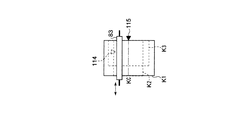
更にまた、本実施の形態において、固定サイドガイド903のサイド初期位置SIPは、図8に示すように、作像モジュール30で許容される最大画像領域Gmax(感光体ドラム31の潜像形成可能領域に相当、本例ではJIS規格A3判サイズ)の側端位置(標準サイド基準位置に相当)に対しa1(本例では16.52mm)離間して設定されている。
尚、中間転写ベルト40の幅寸法は、通常最大画像領域Gmaxを中央部に含んでその両側に余剰部40aを有して設定されているため、前記サイド初期位置SIPと中間転写ベルト40の側端との間は所定寸法b(本例では5mm)だけ離間配置されている。
【0031】
また、本実施の形態に係る画像形成装置では、後述するシートKの搬送処理制御用に各種センサが配置されている。
図3において、符号111は、中間転写ベルト40の周囲のうち、最上流の感光体ドラム31Yの上流側に配設される作像開始センサ、112は二次転写部位の上流側に配設されるマークセンサである。一方、符号113は、シート搬送路のうち、レジロール83の上流側直前に配設されるレジ入口センサ、114はその下流側直後に配設されるレジ出口センサである。更に、符号115は、前記レジ入口センサ113の近傍に配設されるシートKのサイドシフト位置検知用のサイドシフトセンサ(図7参照)である。
ここで、レジ入口センサ113及びレジ出口センサ114は、図5に示すように、シートKの搬送方向と直交する方向に移動自在に配設されており、共に図3に示すレジセンサ駆動モータ61により駆動されるようになっている。
一方、サイドシフトセンサ115は、図5に示すように、シートKの搬送方向に移動自在に配設されており、図3に示すサイドシフトセンサ駆動モータ62により駆動されるようになっている。
【0032】
そして、本実施の形態では、図4に示すシート搬送制御系にてシートKの搬送処理を制御するようになっている。
特に、本実施の形態では、シート搬送路中でシートKを停止させることなく、シートKの搬送速度を制御する方式(シート供給トレイ71〜73等から二次転写部位の直前まで高速レベル(例えば300mm/sec.)で搬送し、所定の減速ポイントにてプロセス速度(低速レベル:例えば150mm/sec.)まで減速した後に二次転写部位に突入させる方式)が採用されている。
そして、シート搬送制御系は、マイクロコンピュータシステムにて構築されたシート搬送制御装置110からなり、図3,図4に示すように、作像開始センサ111、マークセンサ112、レジ入口センサ113、レジ出口センサ114、サイドシフトセンサ115からの各検知信号及びシート情報(サイズ、向き)が入力インターフェース121を介してCPU122に取り込まれ、次に、CPU122は、ROM123に格納されている制御プログラムを実行してRAM124との間で適宜データ処理を行った後、出力インターフェース125を介して、駆動モータ51、N/Rモータ52〜54,56、レジモータ55、サイドシフト機構58、レジセンサ駆動モータ61及びサイドシフトセンサ駆動モータ62に夫々所定の制御信号を送出するようになっている。
【0033】
ここで、各センサ111〜115としては、例えば反射型の光学センサが用いられ、作像開始センサ111、マークセンサ112は中間転写ベルト40上に形成された基準マーク(中間転写ベルト40上に画像位置合わせ用に形成されるトナーパッチや中間転写ベルト40上に予め設けられる画像位置合わせ用の光反射体、透孔など)63を検知し、この基準マーク63に対して所定の位置関係にある画像64の位置を把握するようにしたものである。
一方、レジ入口センサ113、レジ出口センサ114は、レジロール83の前後においてシートKの先端が通過したことを検知するものであり、また、サイドシフトセンサ115はシートKの側端位置が抜けたか否かを検知するものである。
そして、本実施の形態では、シートKの搬送速度を制御するに当たって、中間転写ベルト40上の画像64が二次転写部位に到達するタイミングを予め把握する必要があるから、マークセンサ112及びレジ出口センサ114の検知タイミングの順番がマークセンサ112、レジ出口センサ114となる条件に設定されている。具体的には、マークセンサ112による検知位置と二次転写部位との間の距離L1がレジ出口センサ114による検知位置と二次転写部位との距離L2よりも短く設定されている。
【0034】
次に、本実施の形態に係る画像形成装置の作動を、シート搬送装置を中心に説明する(図3,4,9,10参照)。
まず、シートKの先端(リード)位置を合わせるリードレジ合わせ処理(図9)について説明する。
今、画像形成の開始指示が与えられると、シート搬送制御装置110は作像開始センサ111がオンしたか否かを繰り返し判定し、作像開始センサ111が中間転写ベルト40上の基準マーク63を検知してオンすると、そのオンタイミング(基準マーク検知タイミング)を基に各感光体ドラム31(31Y〜31K)への画像の書込みを開始する。これにより、中間転写ベルト40上には、基準マーク63の位置を基準として、各感光体ドラム31より画像(トナー像)64が順次重ね転写される。
【0035】
次いで、マークセンサ112の検知信号がオンしたか否かを繰り返し判定し、マークセンサ112が中間転写ベルト40上の基準マーク63を検知してオンすると、そのオンタイミング(基準パッチ検知タイミング)を基に、中間転写ベルト40上の画像64が二次転写部位(二次転写ロール50とバックアップロール44との圧接部分)に到達するタイミングを算出する。
このとき、画像64の到達タイミングについては、二次転写部位とマークセンサ112との間の距離L1及び中間転写ベルト40の走行速度を用いて算出すればよい。
ここで、中間転写ベルト40の走行速度については、作像開始センサ111がオンしてから再びオンするまでの時間(中間転写ベルト40の回転周期)と、中間転写ベルト40の周長から正確に割り出すことができる。また、二次転写位置とマークセンサ112との間の距離L1を中間転写ベルト40の駆動ロール41の周長の整数倍に設定しておけば、駆動ロール41の偏心による誤差成分が低減される点で好ましい。
【0036】
一方、図2及び図3において、作像開始センサ111がオンすると、このオンタイミングを基に、シート供給トレイ71〜73あるいは手差しトレイ等からシートKが所定のタイミングで送出され、搬送ロール81群、斜行ロール82及びレジロール83を経て、シート搬送路に沿って順次搬送されていく。
また、シート搬送制御装置110は、入力されたシート情報に基づき、シートKの搬送方向に直交する方向の長さを判定し、これに基づいてレジセンサ駆動モータ61に駆動信号を送出し、レジ出口センサ114をシートKの搬送方向の直交方向中央部に対応する位置(例えばシートKがJISA3判サイズであれば、サイド初期位置SIPから148.5mmの位置)に移動させる。尚、このとき、レジ入口センサ113もこれに追従してシートKの搬送方向の直交方向中央部に対応する位置に移動する。
そして、シート搬送制御装置110はレジ出口センサ114がオンしたか否かを繰り返して判定し、シートKの先端がレジ出口センサ114を通過し、レジ出口センサ114が搬送されてきたシートKの先端を検知してオンすると、そのオンタイミング(シート検知タイミング)を基にシートKの搬送速度の減速タイミングを算出する。尚、本例では、減速タイミングを例示しているが、これに限られるものではなく、高速レベルから低速レベル(プロセス速度)まで多段階に減速したり、あるいは、高速レベルから低速レベルよりも低いレベルに一旦減速した後に低速レベルに移行するなど減速パターンを適宜算出するようにしてもよい。
【0037】
次いで、シート搬送制御装置110は、例えば図15(a)に示すように、先に算出した減速タイミングになったか否かを繰り返し判定し、減速タイミングになった時点(例えば図15(a)においてレジ出口センサ114を通過してからt1経過時点)でシートKの搬送速度を高速レベルから低速レベル(プロセス速度)に減速させる。
この後、シートKが二次転写部位に到達すると、そこで、中間転写ベルト40上に形成された画像(トナー像)64がシートKの所定位置に正確に転写される。
【0038】
また、本実施の形態では、上述したリードレジ合わせ処理(図9参照)と共に、シートKの側端位置を揃えるサイドレジ合わせ処理(図10参照)が行われる。
図10に示すように、シート搬送制御装置110は、まず、これから搬送すべきシートKの情報、具体的にはシートサイズ及び向きを検知し、しかる後に、シートのサイズに応じたサイドシフト量を決定する。本実施の形態において、上述したサイドシフト量の決定方式は、例えばシート情報(サイズ、向き)毎に予め定められた基準位置をメモリに格納しておき、取り込まれたシート情報に対応する基準位置を選択するものである。
【0039】
例えば所謂定型サイズのシートの場合には、JIS規格A3判サイズ以下か、12inchか12.6inchのどれかを判断し、サイド初期位置SIPからのサイドシフト量をaとすれば、
A3判以下の定型サイズ :a1(本例では16.52mm)
12inchの定型サイズ :a2(本例では12.62mm)
12.6inchの定型サイズ:a3(本例では5mm)
に決定し、これらのサイドシフト量a1〜a3については、サイドシフトセンサ115通過後のサイドシフト機構58のサイドシフトモータ584の駆動パルス数(夫々Aパルス、Bパルス、Cパルスとする)にて設定するようにしたものである。
【0040】
尚、本実施の形態にあっては、a 3はサイド初期位置SIPと中間転写ベルト40の側端との間の寸法bよりも大きく設定されており、最大画像領域Gmaxを超えるサイズのシートKであっても、シートK全域が中間転写ベルト40と二次転写ロール50との間にニップされるようになっている。
【0041】
また、シート搬送制御装置110は、上述するようなシートKのサイドシフト量の決定を行う一方、シート供給トレイ71〜73若しくは手差しトレイからシートKを送出する。
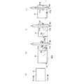
このとき、図2及び図11(a)に示すように、シートKはシート供給トレイ71〜73若しくは手差しトレイのフロント基準位置に揃えられた状態で送出されるが、この段階でのシートKの側端位置の揃え精度はラフに設定されている。尚、図11では、JISA3判のシートKを例に図示している。
【0042】
そして、図2及び図11(b)に示すように、シートKが搬送ロール81群を通過し、斜行ロール82に到達すると、当該シートKは斜行ロール82によって固定サイドガイド903側に斜行移動せしめられ、シートKの側端位置をサイド初期位置SIPに沿わせた状態でレジロール83へと搬送される。
このため、シートKの搬送ロール81群による搬送過程において、シートKがスキューしたとしても、斜行ロール82群を通過する段階でスキュー補正が行われることとなる。
【0043】
一方、図11(b)に示すように、シートKが斜行ロール82に到達する前に、入力されたシート情報に基づき、シートKの搬送方向の長さ及び搬送方向に直交する方向の長さを判定し、これに基づいてレジセンサ駆動モータ61及びサイドシフトセンサ駆動モータ62に駆動信号を送出し、レジ出口センサ114をシートKの搬送方向に直交する方向中央部に対応する位置(例えばシートKがJISA3判サイズであれば、サイド初期位置SIPから148.5mmの位置)に移動させると共に、サイドシフトセンサ115をシートKの搬送方向中央部に対応する位置(JISA3判サイズの場合、レジ出口センサ114から搬送方向上流側210.0mmの位置)に移動させる。尚、レジ出口センサ114の移動に伴い、レジ入口センサ113も同様に移動する。
【0044】
そして、図13(a)(b)に示すように、シートKがレジロール83に突入する前は各斜行ロール82はニップ状態を維持するが、図13(a)(c)に仮想線で示すように、シートKの先端がレジ入口センサ113を通過してから予め決められた所定時間(シートKの先端がレジロール83にニップされるのに十分な時間)経過後に、ニップリリースモータ52〜54にてニップ状態の斜行ロール82をリリースする。
【0045】
この後、図11(c)に示すように、シートKの先端がレジ出口センサ114に到達すると、レジ出口センサ114がオン動作し、これに伴って、シート搬送制御装置110は、図10に示すように、シートKのサイドシフト処理を開始し、サイドシフト機構58(図6、図7参照)にて、シートKがニップされた状態のレジロール83を軸方向に移動させる(図11(d)参照)。
ここで、サイドシフトセンサ115としては、図14(a)に示すように、チャンネル状のセンサケース115aに発光素子115bと受光素子115cとを対向配置した所謂フォトカプラ構成のものが用いられており、サイド初期位置SIPに位置規制されたシートKの側端部が発光素子115bと受光素子115cとの間の空間部を通過するようになっている。
【0046】
この状態において、レジロール83に挟まれたシートKがレジロール83の軸方向に沿って移動していくと、図14(b)に示すように、発光素子115bと受光素子115cとの間の対向部を抜けることになり、この状態において、発光素子115bからの光が受光素子115cに完全に受光されることになり、サイドシフトセンサ115がオン(受光素子115cローレベル)からオフ(受光素子115cハイレベル)に切り替わる(図12(a)参照)。
すると、シート搬送制御装置110は、図10に示すように、サイドシフトセンサ115のオフ信号検知時点から、既に決定されているサイドシフト量に対応するnパルスをカウントし、図14(c)に示すように、nパルス分に対応する分だけシートKをシフトさせる。
このとき、例えばJISA3判サイズ以下のシートKの場合には、n=Aパルスであり、当該シートKはサイド初期位置SIPからa1(16.52mm)の基準位置に設定され、また12inchのシートKの場合にはn=Bパルスであり、当該シートKはサイド初期位置SIPからa2(12.62mm)の基準位置に設定され、更に、12.6inchのシートKの場合には、n=Cパルスであり、当該シートKはサイド初期位置SIPからa3(5mm)の基準位置に設定される。
この段階で、シートKのサイドシフト動作が終了し、レジロール83の軸方向への移動動作が停止され、シートKは各基準位置に揃えられた状態でレジロール83にて搬送される。
【0047】
そして、図12(c)に示すように、シートKがレジロール83を通過し、シートKの後端がレジ出口センサ114を通過すると、シート搬送制御装置110は、レジ出口センサ114がオンからオフになった時点で、サイドシフト機構58によりレジロール83を初期位置に復帰させる。
また、図15(b)に示すように、シートKの先端が二次転写部位へと至ると、シートKの先端部が二次転写ロール50とバックアップロール44との間にニップ搬送されるため、この段階で、シートKの後端がレジロール83を抜けていなければ、ニップリリースモータ56(図3参照)にてニップ状態のレジロール83がリリースされる。
このようなレジロール83のニップリリース方式を採用している理由は次の通りである。
すなわち、第一に、レジロール83をニップ状態のままとすると、例えばシートKが厚紙のときに、レジロール83と中間転写ベルト40との間に速度差が僅かでもあると、レジロール83が相対的に速い場合には中間転写ベルト40が押されたり、逆に、レジロール83が相対的に遅いと中間転写ベルト40が引っ張られることになり、転写動作時に像ずれが生じ易い。これを回避するために、転写動作時にレジロール83をリリースするのである。第二に、レジロール83をサイドシフトする方式にあっては、シートKの後端がレジロール83を通過しなくても、レジロール83を初期位置へ戻すことが可能になる。このため、レジロール83の戻し開始タイミングを速く設定することが可能になり、その分、連続画像形成時におけるインターイメージを狭くすることができ、生産性を向上させることができる。
尚、搬送タイミングが厳しい場合には、シートKの先端部が二次転写ロール50に到達すると、レジロール83のニップを解除すると共に、このレジロール83を初期位置に復帰させ、次のシートKに備えて、シートKの後端がレジロール83を抜けた時点でレジロール83をニップさせるようにしてもよい。
【0048】
そして、二次転写部位において画像(トナー像)64が転写されたシートKは、その後定着器60を経て、後処理ユニット23を経てシート排出トレイ233に排出される。
また、同一のシートKに再度画像形成を行う場合は、定着後のシートKを戻し経路85経由でシート搬送ユニット90側へと再搬送する。
【0049】
ここで、本実施の形態において、サイドシフトセンサ115を用いてシートKの位置設定を行っている理由は、次の通りである。
すなわち、シートKは斜行ロール82にて固定サイドガイド903に押し付けられるので、例えばシートKとして薄紙等を使用すると、腰がないために固定サイドガイド903に当接したシートKが撓んでしまう。このとき、サイドシフトセンサ115を使わずにサイズ、向き毎にシートKに対するサイドシフト量を一定に設定してしまうと、シートKが撓んだような状況下ではシートKのサイドシフト量が見かけ上少なくなり、シートKの位置設定が不正確になり易い。
これに対し、本実施の形態のように、サイドシフトセンサ115を用いてサイドシフト中のシートKの基準位置を見てシートKの基準位置を設定するようにすれば、薄紙等のシートKの種類に影響されることなく、シートKの位置設定を正確に行うことができる。
【0050】
また、本実施の形態において、サイドレジ合わせ処理時に、サイドシフトセンサ115をシートKの搬送方向中央部に対応する位置に移動させているのは、次の理由によるものである。
上述したように、搬送されるシートKは、斜行ロール82群を通過する段階でスキューの補正が行われるのであるが、斜行ロール82群からレジロール83に到達するまでの間に、僅かながら再びスキューが生じることがある。
すると、従来の方式、すなわち図16に示すように、レジロール83の近傍にサイドシフトセンサ115を固定配設するような方式では、シートKの先端部近傍の側端を検知することになるので、センサ前後のぶれが異なり、後端部のシート側端のぶれは大きくなる(このぶれ幅をAとする)。
一方、本実施の形態のように、シートKの搬送方向中央部に対応する位置にサイドシフトセンサ115を移動させて配置する方式にあっては、図16(b)に示すように、センサ前後のぶれが同じ大きさとなるため、そのぶれ幅Bは上述したぶれ幅Aよりも少なくなる。
このように、サイドシフトセンサ115の位置をシート搬送方向中央部に対応する位置とすることで、シートスキューの影響を受けにくくすることができ、サイドレジストレーション整合を精度良く行うことができる。
【0051】
尚、本実施の形態では、サイドシフトセンサ115をシートKの搬送方向に移動自在に配設することで、各種サイズのシートKに対応するようにしていたが、これに限られるものではなく、例えば図17に示すように、各種サイズのシートK(K−1,K−2,K−3)の搬送方向中央部に対応する位置に夫々サイドシフトセンサ115(115−1,115−2,115−3)を固定配設するようにしてもよい。
【0052】
更に、本実施の形態において、リードレジ合わせ処理時及びサイドレジ合わせ処理時に、レジ出口センサ114(及びレジ入口センサ113)をシートKの搬送方向に直交する方向中央部に対応する位置に移動させているのは、次の理由によるものである。
上述したように、レジロール83に到達するまでの間にシートKにスキューが生じた場合、例えば、図18(a)に示すように、レジ出口センサ114がシートKの搬送方向に直交する方向の端部側にあると、センサ左右のぶれが異なり、一端側のぶれが大きくなる(このぶれ幅をCとする)。
一方、本実施の形態のように、シートKの搬送方向に直交する方向中央部に対応する位置にレジ出口センサ114を移動させて配置する方式にあっては、図18(b)に示すように、センサ左右のぶれが同じ大きさとなるため、そのぶれ幅Dは上述したぶれ幅Cよりも少なくなる。
このように、レジ出口センサ114の位置をシート搬送方向に直交する方向中央部に対応する位置とすることで、シートスキューの影響を受けにくくすることができ、リードレジストレーション整合及びサイドレジストレーション整合を精度良く行うことができる。
【0053】
尚、本実施の形態では、レジ出口センサ114をシートKの搬送方向と直交する方向に移動自在に配設することで、各種サイズのシートKに対応するようにしていたが、これに限られるものではなく、例えば図19に示すように、各種サイズのシートK(K−A,K−B,K−C)の搬送方向に直交する方向中央部に対応する位置に夫々レジ出口センサ114(114−A,114−B,114−C)を固定配設するようにしてもよい。
【0054】
◎実施の形態2
本実施の形態は、実施の形態1と略同様であるが、図20に示すように、サイドシフトセンサ115をレジロール83近傍に固定配置し、シートK(K1,K2,K3)のサイズに関わらず、その搬送方向中央部位Kcがサイドシフトセンサ115に到達した時点からサイドシフト機構58を動作させるようにしたものである。
このような態様にあっては、シートKのサイズ(搬送方向長さ)に応じて、シートKの先端がレジ出口センサ114に到達してからその搬送方向中央部位Kcがサイドシフトセンサ115に到達するまでの時間を予めタイマー値として設定しておき、レジ出口センサ114による検知から所定のタイマー値が経過した後にサイドシフトを開始するようにすればよい(図21参照)。
【0055】
本実施の形態においては、サイドシフトセンサ115にシートKの搬送方向中央部位Kcが到達した時点からサイドシフトを開始するようにしたので、実施の形態1と同様に、シートスキューの影響を受けにくくすることができ、サイドレジストレーション整合を精度良く行うことができる。
また、実施の形態1とは異なり、サイドシフトセンサ115の駆動機構が不要となるので、その分構成を簡易化することができる。
【0056】
◎実施の形態3
本実施の形態は、実施の形態1と略同様であるが、図22に示すように、サイドシフトセンサ115(以下、必要に応じてサイドシフトセンサ1という)の他に、第二サイドシフトセンサ116(以下、必要に応じてサイドシフトセンサ2という)を配設するようにしたものである。尚、本実施の形態は、本発明に関連する参考発明(段落〔0013〕参照)を具現化したもので、実施の形態1,2との差異を示すための参考の形態である。
本実施の形態において、第二サイドシフトセンサ116は、サイドシフトセンサ115と同様の構成を有しており、レジロール83よりも下流側すなわち当該サイドシフトセンサ115よりも下流側で、このサイドシフトセンサ115と同じ側に配置されている。
本実施の形態では、シートKのサイドシフトを開始した後、サイドシフトセンサ1,2がオフとなるタイミングの差分からサイドシフト量の補正値を算出し、ノミナル値(暫定サイドシフト量)を補正することでより正確なサイドシフト量を得ることができる(図23参照)。
【0057】
尚、実施の形態1〜3においては、シートKの側端をサイド初期位置SIPに寄せてからサイドシフトを開始し、レジ出口センサ114でシートKの先端を検知してからサイドシフト機構58を動作させる例を示したが、シートKの側端が一定位置になく、一旦サイドシフトセンサ115でシートKの側端が検知されるまで、サイドシフトセンサ115にシートKが近づく方向にサイドシフトを行い、サイドシフトセンサ115でシートKの側端が検知されてから逆方向にサイドシフトを行うタイプのものにも適用可能である。
【0058】
【発明の効果】
以上説明したように、本発明によれば、スキュー補正手段によってスキュー補正を施したシートの先端部が搬送部材対にニップされた状態にて、シートの搬送方向中央部に対応する位置で当該シートの側端を検知しつつサイドシフトを行うようにしたので、シート搬送時に少なからず起こるシートスキューの影響を最小限にすることができ、主としてシートのサイドレジストレーション整合を精度良く行うことができる。
【図面の簡単な説明】
【図1】 (a)(b)は、本発明に係るシート搬送装置の概要を示す概要説明図である。
【図2】 本発明に係るシート搬送装置が適用された画像形成装置の実施の形態1を示す説明図である。
【図3】 実施の形態1に係るシート搬送装置の詳細を示す説明図である。
【図4】 実施の形態1に係るシート搬送装置のシート搬送制御装置の概要を示すブロック図である。
【図5】 (a)はシート搬送ユニットの平面説明図、(b)はその正面説明図である。
【図6】 実施の形態1で用いられるレジロールのサイドシフト機構の詳細を示す斜視図である。
【図7】 実施の形態1で用いられるレジロールのサイドシフト機構の詳細を示す正面図である。
【図8】 実施の形態1で用いられる固定サイドガイドの位置関係を示す説明図である。
【図9】 実施の形態1で用いられるシート搬送制御のリードレジ合わせ処理内容を示すフローチャートである。
【図10】 実施の形態1で用いられるシート搬送制御のサイドレジ合わせ処理内容を示すフローチャートである。
【図11】 (a)〜(d)は実施の形態1のシート搬送過程を示す説明図である。
【図12】 (a)〜(c)は実施の形態1の図11の後のシート搬送過程を示す説明図である。
【図13】 (a)は図11の(b)から(c)に至る間のシートの搬送状態を示す説明図、(b)は(a)においてシートが実線位置にあるときのシート搬送ユニットの各ロールの状態を示す説明図、(c)は(a)においてシートが二点鎖線位置にあるときのシート搬送ユニットの各ロールの状態を示す説明図である。
【図14】 (a)〜(c)は図12(a)から(b)に至る間のシートのサイドシフト動作を模式的に示す説明図である。
【図15】 (a)は二次転写部位に至る前のシートの減速処理を示す説明図、(b)は二次転写部位にシートが至った時点の状態を示す説明図である。
【図16】 (a)は従来の方式、(b)は本発明に係る方式によるシートの搬送方向に直交する方向のずれを模式的に示した説明図である。
【図17】 変形例の一例を示す説明図である。
【図18】 (a)は従来の方式、(b)は本発明に係る方式によるシートの搬送方向のずれを模式的に示した説明図である。
【図19】 変形例の一例を示す説明図である。
【図20】 実施の形態2におけるシート、サイドシフトセンサ、レジロールの関係を示した説明図である。
【図21】 実施の形態2で用いられるシート搬送制御のサイドレジ合わせ処理内容を示すフローチャートである。
【図22】 実施の形態3におけるシート、サイドシフトセンサ1,2、レジロールの関係を示した説明図である。
【図23】 実施の形態3で用いられるシート搬送制御のサイドレジ合わせ処理内容を示すフローチャートである。
【符号の説明】
1…搬送部材対,2…側端検知手段,3…変位手段,4…制御手段,S…シート[0001]
BACKGROUND OF THE INVENTION
The present invention relates to a sheet conveying apparatus that conveys a sheet, and more particularly to an improvement of a sheet conveying apparatus of a type that aligns a sheet during conveyance.
[0002]
[Prior art]
In general, as an image forming apparatus using an electrophotographic method, for example, an electrostatic latent image corresponding to an image signal is formed on a latent image carrier such as a photosensitive drum, and a toner image obtained by developing the latent image is developed. A system in which (image) is transferred directly or through an intermediate transfer member to a sheet such as paper is employed.
In this type of image forming apparatus, in order to accurately transfer an image on the sheet, it is usually performed to align the sheet at a predetermined reference position. There are a lead registration method in which the (lead) is aligned and sent to the transfer site, and a side registration method in which the side edge of the sheet is aligned with a predetermined side reference position and then sent to the transfer site.
[0003]
Here, since the sheet is easy to skew in the lead registration method, image misalignment is likely to occur on the front and back surfaces of the sheet, but in the side registration method, the sheet is always aligned at a predetermined side reference position. This is preferable in that the displacement of the image on the front and back surfaces of the sheet can be reduced.
As an example of such a side registration type sheet conveying apparatus, a registration roll or the like is disposed so as to be movable in a direction perpendicular to the sheet conveying direction, and a sensor for detecting the edge of the sheet in the vicinity of the registration roll. A technique for positioning the sheet at a predetermined side reference position by controlling the movement amount (side shift amount) of the registration roll based on the detection result of the sensor is already known (for example, Japanese Patent Laid-Open No. Sho 61). -249063, JP-A-2-198952).
[0004]
[Problems to be solved by the invention]
Incidentally, even in the above-described side registration type sheet conveying apparatus, the posture of the sheet may vary during sheet conveyance, which may cause side skew.
Then, in the sheet conveying apparatus described above, the sheet is skewed because the side shift operation is started immediately after the sheet is nipped by the registration roll, that is, when the side edge on the leading edge side of the sheet passes the sensor. In this case, the timing at which the side shift sensor should originally perform the detection and the timing at which the side shift sensor actually performs the detection are deviated, which affects the alignment of the side register and causes an excessive or insufficient side shift amount.
[0005]
Also known is a lead registration type sheet conveying apparatus that is provided with a sensor for detecting the position of the leading or trailing edge of the sheet, and that performs acceleration / deceleration and timing adjustment of the sheet conveying speed based on the detection result of the sensor. However, even in such a sheet conveying apparatus, depending on the position of the sensor, when the sheet posture varies during sheet conveyance and a lead skew occurs, This will affect the read registration alignment.
[0006]
The present invention has been made in order to solve the above technical problem, and minimizes the effect of sheet skew that occurs at least during sheet conveyance.mainlySheetsideIt is an object of the present invention to provide a sheet conveying apparatus capable of performing registration alignment with high accuracy.
[0007]
[Means for Solving the Problems]
That is, the present invention1 (a) and 1 (b)As shown inSeveral different sizesA pair of conveying
[0008]
In such a technical means, the conveying
[0009]
Further, as long as the side
[0010]
Further, the displacing means 3 only needs to have a function of displacing the conveying
[0011]
In the present invention, the side
As a method for arranging the side edge detecting means 2, for example, from the viewpoint of appropriately dealing with a plurality of sheets having different sizes, a method of arranging the side edge detecting means 2 movably along the sheet conveying direction, or a sheet conveying method. It is preferable to employ a method of arranging a plurality of the members along the direction. Further, the side edge detecting means 2 may be fixedly disposed at a position corresponding to the central portion in the conveyance direction of at least one standard size sheet. And in such an aspect, it is good to arrange | position the side edge detection means 2 in the position corresponding to the center part of the conveyance direction of the size of the most frequently used sheet.
[0012]
Moreover, if this invention is taken from another viewpoint, as shown to FIG. 1 (a) (b),Several different sizesA pair of conveying
[0013]
Furthermore,As reference inventions related to the present invention,A pair of conveying members that nip and convey a plurality of sheets of different sizes, and nip the sheet toward a preset side edge alignment initial position that is located upstream of the conveying member pair in the sheet conveying direction. A pair of skew conveying members capable of nip release for skew conveyance, and side edge detection for detecting a side edge of the sheet positioned upstream of the pair of conveying members and nipped by the pair of conveying members. And a second side end detection unit that is disposed upstream or downstream in the sheet conveyance direction of the side edge detection unit and detects a side edge of a sheet on the same side as the side edge detection unit, and the conveyance member pair. A displacement means for displacing the conveying member pair in a direction orthogonal to the conveying direction of the sheet while the sheet is nipped in the sheet, and the skew of the sheet nip state before the leading end of the sheet is nipped by the conveying member pair Transport unit Based on the detection results of the side edge detection means and the second side edge detection means in a state where the sheet is nipped between the conveyance member pair and the conveyance member pair of the conveyance member pair Control means for controlling the amount of displacement, and the control means starts the detection operation by the side edge detection means and the second side edge detection means in a state where the leading edge of the sheet is nipped between the pair of conveying members. And starting displacement control of the conveying member pairIs mentioned.
[0014]
In such technical means, the conveying member pair, the side end detecting means, the displacing means, and the control means may be appropriately selected from the same as described above.
As for the second side end detection means, the second side end detection means is provided on the upstream side or the downstream side of the side end detection means, and can detect the side edge of the sheet on the same side as the side end detection means. It may be appropriately selected from the same end detection means.
Further, with respect to the correcting means, the skew amount of the sheet is determined based on the detection results of the side edge detecting means and the second side edge detecting means, and the sheet skew is determined accordinglyDisplacement meansAs long as the amount of displacement of the conveying member pair is corrected, it may be selected as appropriate.
[0015]
In addition, the present inventionIn addition,Sheet lead registrationConsideredAs an aspect, there is provided an end detection unit that detects a leading end or a rear end of a sheet nipped by the pair of conveyance members, and the end detection unit corresponds to a central portion in a direction perpendicular to the conveyance direction of the conveyed sheet. The thing arrange | positioned in the position to do is mentioned.
[0016]
In such technical means, the conveying member pair may be appropriately selected from the same ones as described above.
In addition, as long as the edge detection means detects the leading edge or the trailing edge position of the sheet nipped by the pair of conveying members, the detection method may be appropriately selected from various methods.
[0017]
And in such an aspect, the said edge detection means is arrange | positioned in the position corresponding to the direction center part orthogonal to the conveyance direction of the conveyed sheet.
As an arrangement method of the edge detection means, for example, from the viewpoint of appropriately dealing with a plurality of sheets of different sizes, a method of arranging the edge detection means movably along a direction orthogonal to the sheet conveyance direction, or sheet conveyance It is preferable to employ a method in which a plurality of arrangements are made along a direction orthogonal to the direction.
[0018]
DETAILED DESCRIPTION OF THE INVENTION
Hereinafter, the present invention will be described in detail based on embodiments shown in the accompanying drawings.
FIG. 2 is an explanatory
In the figure, the image forming apparatus according to the present embodiment is an image forming apparatus that employs a so-called tandem intermediate transfer system, and includes an
[0019]
In the present embodiment, the
[0020]
In the present embodiment, around each
Further, the
In this embodiment, the intermediate transfer belt40A portion facing the
[0021]
Further, in the present embodiment, the
In particular, in the present embodiment, the
Then, after the sheet conveyance path from the
On the other hand, the sheet conveyance path from the
[0022]
Further, a plurality of paired conveyance rolls 81 are provided at predetermined intervals in the
The
Further, in the present exemplary embodiment, a
[0023]
Further, in the present embodiment, an
The
[0024]
Furthermore, in the present embodiment, the
In this example, the
Furthermore, an
[0025]
Further, the sheet conveyance path in the
In particular, in the present embodiment, as the
Further, the sheet K after passing through the secondary transfer site is conveyed to the fixing
[0026]
Further, as the sheet return mechanism used in the present embodiment, the sheet K fed from the fixing
A part of the
[0027]
Next, the
In the present embodiment, as shown in FIG. 5, the
The
[0028]
As shown in FIGS. 3 to 5, the
As shown in FIGS. 3 to 7, the
[0029]
Further, as shown in FIGS. 3 to 7, the registration roll 83 (831, 832) is rotatably supported by the
The
In FIG. 7, the
[0030]
Furthermore, in the present embodiment, the initial side position SIP of the fixed
The width dimension of the
[0031]
Further, in the image forming apparatus according to the present embodiment, various sensors are arranged for controlling the sheet K conveyance processing described later.
In FIG. 3,
Here, as shown in FIG. 5, the
On the other hand, as shown in FIG. 5, the
[0032]
In this embodiment, the sheet K conveyance process is controlled by the sheet conveyance control system shown in FIG.
In particular, in the present embodiment, a method of controlling the conveyance speed of the sheet K without stopping the sheet K in the sheet conveyance path (from the
The sheet conveyance control system includes a sheet
[0033]
Here, as each of the
On the other hand, the
In this embodiment, when controlling the conveyance speed of the sheet K, it is necessary to grasp in advance the timing at which the
[0034]
Next, the operation of the image forming apparatus according to the present embodiment will be described focusing on the sheet conveying apparatus (see FIGS. 3, 4, 9, and 10).
First, the lead registration aligning process (FIG. 9) for aligning the leading edge (lead) position of the sheet K will be described.
Now, when an image formation start instruction is given, the sheet
[0035]
Next, it is repeatedly determined whether or not the detection signal of the
At this time, the arrival timing of the
Here, the traveling speed of the
[0036]
On the other hand, in FIG. 2 and FIG. 3, when the image forming
Further, the sheet
Then, the sheet
[0037]
Next, for example, as shown in FIG. 15A, the sheet
Thereafter, when the sheet K reaches the secondary transfer portion, the image (toner image) 64 formed on the
[0038]
In the present embodiment, in addition to the above-described lead registration process (see FIG. 9), a side registration process (see FIG. 10) for aligning the side edge positions of the sheet K is performed.
As shown in FIG. 10, the sheet
[0039]
For example, in the case of a so-called standard size sheet, if it is determined whether it is smaller than JIS standard A3 size, 12 inch or 12.6 inch, and the side shift amount from the side initial position SIP is a,
Standard size below A3 size: a1 (16.52 mm in this example)
Standard size of 12 inch: a2 (12.62 mm in this example)
12.6 inch standard size: a3 (5mm in this example)
The side shift amounts a1 to a3 are determined by the number of drive pulses of the
[0040]
In this embodiment,a ThreeIs set to be larger than the dimension b between the side initial position SIP and the side edge of the
[0041]
Further, the sheet
At this time, as shown in FIGS. 2 and 11A, the sheet K is sent out in a state where it is aligned with the front reference position of the
[0042]
As shown in FIGS. 2 and 11B, when the sheet K passes through the conveying
For this reason, even if the sheet K is skewed in the process of transporting the sheet K by the
[0043]
On the other hand, as shown in FIG. 11B, before the sheet K reaches the
[0044]
As shown in FIGS. 13A and 13B, each
[0045]
Thereafter, as shown in FIG. 11C, when the leading edge of the sheet K reaches the
Here, as the
[0046]
In this state, when the sheet K sandwiched between the registration rolls 83 moves along the axial direction of the
Then, as shown in FIG. 10, the sheet
At this time, for example, in the case of a sheet K having a size of JIS A3 or less, n = A pulse, the sheet K is set to a reference position a1 (16.52 mm) from the side initial position SIP, and a 12-inch sheet K In this case, n = B pulse, and the sheet K is set to a reference position a2 (12.62 mm) from the side initial position SIP. Further, in the case of a 12.6 inch sheet K, n = C pulse. The sheet K is set at a reference position a3 (5 mm) from the side initial position SIP.
At this stage, the side shift operation of the sheet K is finished, the movement operation of the
[0047]
Then, as shown in FIG. 12C, when the sheet K passes the
Also, as shown in FIG. 15B, when the leading edge of the sheet K reaches the secondary transfer site, the leading edge of the sheet K is nipped between the
The reason why such a
That is, first, if the
If the conveyance timing is severe, when the leading edge of the sheet K reaches the
[0048]
Then, an image (toner image) at the secondary transfer site64Then, the sheet K on which is transferred is discharged to the
When image formation is performed again on the same sheet K, the fixed sheet K is re-conveyed to the
[0049]
Here, in the present embodiment, the reason why the position of the sheet K is set using the
That is, since the sheet K is pressed against the fixed
On the other hand, if the reference position of the sheet K is set by looking at the reference position of the sheet K during the side shift using the
[0050]
In the present embodiment, the
As described above, the skew of the conveyed sheet K is corrected when it passes through the
Then, in the conventional method, that is, as shown in FIG. 16, in the method in which the
On the other hand, in the system in which the
As described above, by setting the position of the
[0051]
In the present embodiment, the
[0052]
Further, in the present embodiment, the registration exit sensor 114 (and the registration entrance sensor 113) is moved to a position corresponding to the central portion in the direction orthogonal to the sheet K conveyance direction during the lead registration alignment process and the side registration alignment process. The reason is as follows.
As described above, when skew occurs in the sheet K before reaching the
On the other hand, as in the present embodiment, in the system in which the
Thus, by setting the position of the
[0053]
In the present embodiment, the
[0054]
Although the present embodiment is substantially the same as the first embodiment, as shown in FIG. 20, the
In such an embodiment, the central portion Kc in the conveyance direction reaches the
[0055]
In the present embodiment, since the side shift is started from the time when the central portion Kc in the conveyance direction of the sheet K reaches the
Further, unlike the first embodiment, the drive mechanism for the
[0056]
The present embodiment is substantially the same as the first embodiment, but, as shown in FIG. 22, in addition to the side shift sensor 115 (hereinafter referred to as the
In the present embodiment, the second side shift sensor 116 has the same configuration as that of the
In the present embodiment, after the side shift of the seat K is started, the correction value of the side shift amount is calculated from the difference in timing when the
[0057]
In the first to third embodiments, the side shift is started after the side edge of the sheet K is brought to the side initial position SIP, and the
[0058]
【The invention's effect】
As described above, according to the present invention, the sheet is corrected at the position corresponding to the central portion in the sheet conveyance direction in a state where the leading edge of the sheet subjected to skew correction by the skew correction unit is nipped by the conveyance member pair. Since the side shift is performed while detecting the side edge of the sheet, it is possible to minimize the effect of sheet skew that occurs at a time during sheet conveyance.mainlySheetsideRegistration matching can be performed with high accuracy.
[Brief description of the drawings]
FIGS. 1A and 1B are schematic explanatory views showing an outline of a sheet conveying apparatus according to the present invention.
FIG. 2 is an explanatory diagram illustrating a first embodiment of an image forming apparatus to which a sheet conveying device according to the invention is applied.
FIG. 3 is an explanatory diagram illustrating details of the sheet conveying apparatus according to the first embodiment.
FIG. 4 is a block diagram illustrating an outline of a sheet conveyance control device of the sheet conveyance device according to the first embodiment.
5A is an explanatory plan view of a sheet conveying unit, and FIG. 5B is an explanatory front view thereof.
6 is a perspective view showing details of a side shift mechanism of a registration roll used in
7 is a front view showing details of a side shift mechanism of a registration roll used in
FIG. 8 is an explanatory diagram showing a positional relationship of fixed side guides used in the first embodiment.
FIG. 9 is a flowchart illustrating the contents of read registration adjustment processing for sheet conveyance control used in the first exemplary embodiment.
FIG. 10 is a flowchart showing the contents of side registration adjustment processing of sheet conveyance control used in the first embodiment.
FIGS. 11A to 11D are explanatory diagrams illustrating a sheet conveying process according to the first embodiment.
FIGS. 12A to 12C are explanatory views showing a sheet conveying process after FIG. 11 of the first embodiment.
13A is an explanatory diagram illustrating a sheet conveyance state from FIG. 11B to FIG. 11C, and FIG. 13B is a sheet conveyance unit when the sheet is in a solid line position in FIG. Explanatory drawing which shows the state of each roll of (a), (c) is explanatory drawing which shows the state of each roll of a sheet | seat conveyance unit when a sheet | seat exists in a dashed-two dotted line position in (a).
FIGS. 14A to 14C are explanatory views schematically showing the side shift operation of the sheet during the period from FIGS. 12A to 12B. FIGS.
FIGS. 15A and 15B are explanatory views showing a sheet deceleration process before reaching the secondary transfer portion, and FIG. 15B are explanatory views showing a state at the time when the sheet reaches the secondary transfer portion.
FIGS. 16A and 16B are explanatory diagrams schematically showing a shift in a direction perpendicular to the sheet conveyance direction according to the conventional method, and FIG. 16B according to the method according to the present invention.
FIG. 17 is an explanatory diagram showing an example of a modification.
FIGS. 18A and 18B are explanatory diagrams schematically showing a shift in the sheet conveyance direction by the conventional method, and FIG. 18B by the method according to the present invention.
FIG. 19 is an explanatory diagram showing an example of a modification.
FIG. 20 is an explanatory diagram showing a relationship among a sheet, a side shift sensor, and a registration roll in the second embodiment.
FIG. 21 is a flowchart showing the contents of side registration adjustment processing of sheet conveyance control used in the second embodiment.
FIG. 22 is an explanatory diagram showing a relationship among a sheet,
FIG. 23 is a flowchart showing the contents of side registration adjustment processing of sheet conveyance control used in the third embodiment.
[Explanation of symbols]
DESCRIPTION OF
Claims (8)
前記搬送部材対よりもシート搬送方向上流側に位置し且つ予め設定されたシートの側端整合初期位置に向けてシートをニップして斜行搬送するニップリリース可能な斜行搬送部材対と、
前記搬送部材対よりもシート搬送方向上流側に位置し且つ前記搬送部材対にニップされたシートの側端を検知する側端検知手段と、
前記搬送部材対にシートがニップされた状態で、当該搬送部材対をシートの搬送方向と直交する方向に変位させる変位手段と、
前記搬送部材対にシートの先端部がニップされる前にシートニップ状態の斜行搬送部材対をリリースし、前記搬送部材対にシートの先端部がニップされた状態にて前記側端検知手段による検知結果に基づいて、前記変位手段による前記搬送部材対の変位量を制御する制御手段とを備え、
前記側端検知手段は、前記搬送部材対にシートの先端部がニップされた状態にて前記制御手段による変位制御開始時の使用シートの搬送方向中央部に対応する位置に配置されることを特徴とするシート搬送装置。A pair of conveying members that nip and convey a plurality of different sized sheets;
A pair of skew conveying members capable of nip release that nips and conveys a sheet toward a preset side edge alignment initial position of the sheet, which is located upstream of the conveying member pair in the sheet conveying direction;
Side edge detection means for detecting the side edge of the sheet positioned upstream of the conveying member pair in the sheet conveying direction and nipped by the conveying member pair;
A displacement means for displacing the conveying member pair in a direction perpendicular to the conveying direction of the sheet in a state where the sheet is nipped by the conveying member pair;
The skew conveying member pair in the sheet nip state is released before the leading end portion of the sheet is nipped by the conveying member pair, and the side end detecting means in the state where the leading end portion of the sheet is nipped by the conveying member pair. Control means for controlling the amount of displacement of the conveying member pair by the displacement means based on the detection result;
The side edge detection unit is disposed at a position corresponding to a central portion in the conveyance direction of a used sheet when displacement control is started by the control unit in a state where the leading end of the sheet is nipped between the pair of conveyance members. A sheet conveying apparatus.
前記側端検知手段は、シート搬送方向に沿って移動自在に配設されることを特徴とするシート搬送装置。In the sheet conveying apparatus according to claim 1,
The sheet conveying apparatus according to claim 1, wherein the side edge detecting means is movably disposed along the sheet conveying direction.
前記側端検知手段は、シート搬送方向に沿って複数配設されることを特徴とするシート搬送装置。In the sheet conveying apparatus according to claim 1,
A plurality of the side edge detecting means are arranged along the sheet conveying direction.
前記側端検知手段は、少なくとも一つの定型サイズのシートの搬送方向中央部に対応する位置に固定配設されることを特徴とするシート搬送装置。In the sheet conveying apparatus according to claim 1,
The sheet conveying apparatus, wherein the side edge detecting unit is fixedly disposed at a position corresponding to a central portion in the conveying direction of at least one standard size sheet.
前記搬送部材対よりもシート搬送方向上流側に位置し且つ予め設定されたシートの側端整合初期位置に向けてシートをニップして斜行搬送するニップリリース可能な斜行搬送部材対と、
前記搬送部材対よりもシート搬送方向上流側に位置し且つ前記搬送部材対にニップされたシートの側端を検知する側端検知手段と、
前記搬送部材対にシートがニップされた状態で、当該搬送部材対をシートの搬送方向と直交する方向に変位させる変位手段と、
前記搬送部材対にシートの先端部がニップされる前にシートニップ状態の斜行搬送部材対をリリースし、前記搬送部材対にシートの先端部がニップされた状態にて前記側端検知手段による検知結果に基づいて、前記変位手段による前記搬送部材対の変位量を制御する制御手段とを備え、
前記制御手段は、前記搬送部材対にシートの先端部がニップされた状態にて搬送される使用シートの搬送方向中央部が前記側端検知手段に到達した時点で、前記搬送部材対の変位制御を開始することを特徴とするシート搬送装置。A pair of conveying members that nip and convey a plurality of different sized sheets;
A pair of skew conveying members capable of nip release that nips and conveys a sheet toward a preset side edge alignment initial position of the sheet, which is located upstream of the conveying member pair in the sheet conveying direction;
Side edge detection means for detecting the side edge of the sheet positioned upstream of the conveying member pair in the sheet conveying direction and nipped by the conveying member pair;
A displacement means for displacing the conveying member pair in a direction perpendicular to the conveying direction of the sheet in a state where the sheet is nipped by the conveying member pair;
The skew conveying member pair in the sheet nip state is released before the leading end portion of the sheet is nipped by the conveying member pair, and the side end detecting means in the state where the leading end portion of the sheet is nipped by the conveying member pair. Control means for controlling the amount of displacement of the conveying member pair by the displacement means based on the detection result;
The control means controls the displacement of the conveying member pair when the central portion in the conveying direction of the used sheet conveyed with the leading edge of the sheet nipped by the conveying member pair reaches the side edge detecting means. The sheet conveying apparatus characterized by starting.
前記搬送部材対にニップされたシートの先端若しくは後端を検知する端部検知手段を備え、
前記端部検知手段が、搬送されるシートの搬送方向に直交する方向中央部に対応する位置に配置されることを特徴とするシート搬送装置。In the sheet conveying apparatus according to claim 1 or 5 ,
An edge detection means for detecting the leading edge or the trailing edge of the sheet nipped by the conveying member pair;
The sheet conveying apparatus, wherein the end detection unit is disposed at a position corresponding to a central portion in a direction orthogonal to a conveying direction of a conveyed sheet.
前記端部検知手段が、シート搬送方向に直交する方向に沿って移動自在に配設されることを特徴とするシート搬送装置。The sheet conveying apparatus according to claim 6 ,
The sheet conveying apparatus, wherein the end detection means is movably disposed along a direction orthogonal to the sheet conveying direction.
前記端部検知手段は、シート搬送方向に直交する方向に沿って複数配設されることを特徴とするシート搬送装置。The sheet conveying apparatus according to claim 6 ,
A plurality of the edge detection means are arranged along a direction orthogonal to the sheet conveyance direction.
Priority Applications (1)
| Application Number | Priority Date | Filing Date | Title |
|---|---|---|---|
| JP2000268229A JP3947899B2 (en) | 2000-09-05 | 2000-09-05 | Sheet transport device |
Applications Claiming Priority (1)
| Application Number | Priority Date | Filing Date | Title |
|---|---|---|---|
| JP2000268229A JP3947899B2 (en) | 2000-09-05 | 2000-09-05 | Sheet transport device |
Publications (3)
| Publication Number | Publication Date |
|---|---|
| JP2002080146A JP2002080146A (en) | 2002-03-19 |
| JP2002080146A5 JP2002080146A5 (en) | 2005-08-04 |
| JP3947899B2 true JP3947899B2 (en) | 2007-07-25 |
Family
ID=18755035
Family Applications (1)
| Application Number | Title | Priority Date | Filing Date |
|---|---|---|---|
| JP2000268229A Expired - Fee Related JP3947899B2 (en) | 2000-09-05 | 2000-09-05 | Sheet transport device |
Country Status (1)
| Country | Link |
|---|---|
| JP (1) | JP3947899B2 (en) |
Families Citing this family (3)
| Publication number | Priority date | Publication date | Assignee | Title |
|---|---|---|---|---|
| JP3927964B2 (en) | 2004-03-31 | 2007-06-13 | キヤノン株式会社 | Sheet conveying apparatus, image forming apparatus, and image reading apparatus |
| JP2008189395A (en) * | 2007-01-31 | 2008-08-21 | Canon Inc | Sheet conveying device and image forming device |
| JP2013147350A (en) * | 2011-12-20 | 2013-08-01 | Ricoh Co Ltd | Sheet processing device, image forming system and sheet processing method |
-
2000
- 2000-09-05 JP JP2000268229A patent/JP3947899B2/en not_active Expired - Fee Related
Also Published As
| Publication number | Publication date |
|---|---|
| JP2002080146A (en) | 2002-03-19 |
Similar Documents
| Publication | Publication Date | Title |
|---|---|---|
| JP3744728B2 (en) | Sheet conveying apparatus and image forming apparatus using the same | |
| US7445208B2 (en) | Sheet conveying apparatus | |
| US9221647B2 (en) | Sheet folding apparatus, image forming apparatus, and image forming system | |
| JP5445510B2 (en) | Conveying apparatus and image forming apparatus | |
| JP3926639B2 (en) | Paper reversing method, paper reversing device, and image forming apparatus | |
| JP5371409B2 (en) | Image forming apparatus | |
| JP5606486B2 (en) | Skew correction device and image forming apparatus | |
| JPH0624620A (en) | Carry path changeover device | |
| JP3947899B2 (en) | Sheet transport device | |
| JP5482163B2 (en) | Curl correction device and image forming apparatus having the same | |
| US6445903B2 (en) | Image forming apparatus having a sheet reversing device | |
| JP4376196B2 (en) | Image forming apparatus | |
| JP3882533B2 (en) | Paper conveying apparatus and image forming apparatus | |
| JP2004323212A (en) | Sheet carrying device and sheet processing device using the device | |
| JP2009292590A (en) | Sheet carrying device and image forming device | |
| JP2006008370A (en) | Paper delivery device | |
| JP2003081529A (en) | Paper sheets folding device and post-treatment device | |
| JP6699431B2 (en) | Paper transport device and image forming device | |
| JP3900766B2 (en) | Image forming apparatus | |
| JP2005089009A (en) | Image formation device | |
| JP2004299803A (en) | Sheet carrier, and sheet processing device having the same | |
| JP2002316748A (en) | Paper feeder and image forming device | |
| JP3791779B2 (en) | Curling correction device for discharged paper in image forming apparatus | |
| JP2018140869A (en) | Image forming apparatus | |
| JP2004284741A (en) | Sheet transport device and sheet handling device equipped with it |
Legal Events
| Date | Code | Title | Description |
|---|---|---|---|
| A621 | Written request for application examination |
Free format text: JAPANESE INTERMEDIATE CODE: A621 Effective date: 20040921 |
|
| A521 | Written amendment |
Free format text: JAPANESE INTERMEDIATE CODE: A523 Effective date: 20050107 |
|
| A977 | Report on retrieval |
Free format text: JAPANESE INTERMEDIATE CODE: A971007 Effective date: 20061031 |
|
| A131 | Notification of reasons for refusal |
Free format text: JAPANESE INTERMEDIATE CODE: A131 Effective date: 20061108 |
|
| A521 | Written amendment |
Free format text: JAPANESE INTERMEDIATE CODE: A523 Effective date: 20070109 |
|
| A131 | Notification of reasons for refusal |
Free format text: JAPANESE INTERMEDIATE CODE: A131 Effective date: 20070214 |
|
| A521 | Written amendment |
Free format text: JAPANESE INTERMEDIATE CODE: A523 Effective date: 20070223 |
|
| TRDD | Decision of grant or rejection written | ||
| A01 | Written decision to grant a patent or to grant a registration (utility model) |
Free format text: JAPANESE INTERMEDIATE CODE: A01 Effective date: 20070322 |
|
| A61 | First payment of annual fees (during grant procedure) |
Free format text: JAPANESE INTERMEDIATE CODE: A61 Effective date: 20070404 |
|
| R150 | Certificate of patent or registration of utility model |
Free format text: JAPANESE INTERMEDIATE CODE: R150 |
|
| FPAY | Renewal fee payment (event date is renewal date of database) |
Free format text: PAYMENT UNTIL: 20110427 Year of fee payment: 4 |
|
| FPAY | Renewal fee payment (event date is renewal date of database) |
Free format text: PAYMENT UNTIL: 20120427 Year of fee payment: 5 |
|
| FPAY | Renewal fee payment (event date is renewal date of database) |
Free format text: PAYMENT UNTIL: 20130427 Year of fee payment: 6 |
|
| LAPS | Cancellation because of no payment of annual fees |