CN108732888B - Sheet conveying apparatus and image forming apparatus - Google Patents
Sheet conveying apparatus and image forming apparatus Download PDFInfo
- Publication number
- CN108732888B CN108732888B CN201810364060.XA CN201810364060A CN108732888B CN 108732888 B CN108732888 B CN 108732888B CN 201810364060 A CN201810364060 A CN 201810364060A CN 108732888 B CN108732888 B CN 108732888B
- Authority
- CN
- China
- Prior art keywords
- sheet
- conveying
- conveyed
- rotating
- speed
- Prior art date
- Legal status (The legal status is an assumption and is not a legal conclusion. Google has not performed a legal analysis and makes no representation as to the accuracy of the status listed.)
- Active
Links
Images


Classifications
-
- B—PERFORMING OPERATIONS; TRANSPORTING
- B65—CONVEYING; PACKING; STORING; HANDLING THIN OR FILAMENTARY MATERIAL
- B65H—HANDLING THIN OR FILAMENTARY MATERIAL, e.g. SHEETS, WEBS, CABLES
- B65H5/00—Feeding articles separated from piles; Feeding articles to machines
- B65H5/06—Feeding articles separated from piles; Feeding articles to machines by rollers or balls, e.g. between rollers
- B65H5/062—Feeding articles separated from piles; Feeding articles to machines by rollers or balls, e.g. between rollers between rollers or balls
-
- B—PERFORMING OPERATIONS; TRANSPORTING
- B65—CONVEYING; PACKING; STORING; HANDLING THIN OR FILAMENTARY MATERIAL
- B65H—HANDLING THIN OR FILAMENTARY MATERIAL, e.g. SHEETS, WEBS, CABLES
- B65H5/00—Feeding articles separated from piles; Feeding articles to machines
- B65H5/26—Duplicate, alternate, selective, or coacting feeds
-
- G—PHYSICS
- G03—PHOTOGRAPHY; CINEMATOGRAPHY; ANALOGOUS TECHNIQUES USING WAVES OTHER THAN OPTICAL WAVES; ELECTROGRAPHY; HOLOGRAPHY
- G03G—ELECTROGRAPHY; ELECTROPHOTOGRAPHY; MAGNETOGRAPHY
- G03G15/00—Apparatus for electrographic processes using a charge pattern
- G03G15/65—Apparatus which relate to the handling of copy material
- G03G15/6555—Handling of sheet copy material taking place in a specific part of the copy material feeding path
- G03G15/6579—Refeeding path for composite copying
-
- B—PERFORMING OPERATIONS; TRANSPORTING
- B65—CONVEYING; PACKING; STORING; HANDLING THIN OR FILAMENTARY MATERIAL
- B65H—HANDLING THIN OR FILAMENTARY MATERIAL, e.g. SHEETS, WEBS, CABLES
- B65H15/00—Overturning articles
-
- B—PERFORMING OPERATIONS; TRANSPORTING
- B65—CONVEYING; PACKING; STORING; HANDLING THIN OR FILAMENTARY MATERIAL
- B65H—HANDLING THIN OR FILAMENTARY MATERIAL, e.g. SHEETS, WEBS, CABLES
- B65H5/00—Feeding articles separated from piles; Feeding articles to machines
- B65H5/36—Article guides or smoothers, e.g. movable in operation
- B65H5/38—Article guides or smoothers, e.g. movable in operation immovable in operation
-
- B—PERFORMING OPERATIONS; TRANSPORTING
- B65—CONVEYING; PACKING; STORING; HANDLING THIN OR FILAMENTARY MATERIAL
- B65H—HANDLING THIN OR FILAMENTARY MATERIAL, e.g. SHEETS, WEBS, CABLES
- B65H7/00—Controlling article feeding, separating, pile-advancing, or associated apparatus, to take account of incorrect feeding, absence of articles, or presence of faulty articles
-
- B—PERFORMING OPERATIONS; TRANSPORTING
- B65—CONVEYING; PACKING; STORING; HANDLING THIN OR FILAMENTARY MATERIAL
- B65H—HANDLING THIN OR FILAMENTARY MATERIAL, e.g. SHEETS, WEBS, CABLES
- B65H85/00—Recirculating articles, i.e. feeding each article to, and delivering it from, the same machine work-station more than once
-
- B—PERFORMING OPERATIONS; TRANSPORTING
- B65—CONVEYING; PACKING; STORING; HANDLING THIN OR FILAMENTARY MATERIAL
- B65H—HANDLING THIN OR FILAMENTARY MATERIAL, e.g. SHEETS, WEBS, CABLES
- B65H9/00—Registering, e.g. orientating, articles; Devices therefor
- B65H9/16—Inclined tape, roller, or like article-forwarding side registers
- B65H9/166—Roller
-
- G—PHYSICS
- G03—PHOTOGRAPHY; CINEMATOGRAPHY; ANALOGOUS TECHNIQUES USING WAVES OTHER THAN OPTICAL WAVES; ELECTROGRAPHY; HOLOGRAPHY
- G03G—ELECTROGRAPHY; ELECTROPHOTOGRAPHY; MAGNETOGRAPHY
- G03G15/00—Apparatus for electrographic processes using a charge pattern
- G03G15/22—Apparatus for electrographic processes using a charge pattern involving the combination of more than one step according to groups G03G13/02 - G03G13/20
- G03G15/23—Apparatus for electrographic processes using a charge pattern involving the combination of more than one step according to groups G03G13/02 - G03G13/20 specially adapted for copying both sides of an original or for copying on both sides of a recording or image-receiving material
- G03G15/231—Arrangements for copying on both sides of a recording or image-receiving material
- G03G15/232—Arrangements for copying on both sides of a recording or image-receiving material using a single reusable electrographic recording member
- G03G15/234—Arrangements for copying on both sides of a recording or image-receiving material using a single reusable electrographic recording member by inverting and refeeding the image receiving material with an image on one face to the recording member to transfer a second image on its second face, e.g. by using a duplex tray; Details of duplex trays or inverters
-
- B—PERFORMING OPERATIONS; TRANSPORTING
- B65—CONVEYING; PACKING; STORING; HANDLING THIN OR FILAMENTARY MATERIAL
- B65H—HANDLING THIN OR FILAMENTARY MATERIAL, e.g. SHEETS, WEBS, CABLES
- B65H2301/00—Handling processes for sheets or webs
- B65H2301/30—Orientation, displacement, position of the handled material
- B65H2301/33—Modifying, selecting, changing orientation
- B65H2301/333—Inverting
- B65H2301/3331—Involving forward reverse transporting means
- B65H2301/33312—Involving forward reverse transporting means forward reverse rollers pairs
-
- B—PERFORMING OPERATIONS; TRANSPORTING
- B65—CONVEYING; PACKING; STORING; HANDLING THIN OR FILAMENTARY MATERIAL
- B65H—HANDLING THIN OR FILAMENTARY MATERIAL, e.g. SHEETS, WEBS, CABLES
- B65H2301/00—Handling processes for sheets or webs
- B65H2301/50—Auxiliary process performed during handling process
- B65H2301/51—Modifying a characteristic of handled material
- B65H2301/512—Changing form of handled material
- B65H2301/5121—Bending, buckling, curling, bringing a curvature
- B65H2301/51212—Bending, buckling, curling, bringing a curvature perpendicularly to the direction of displacement of handled material, e.g. forming a loop
-
- B—PERFORMING OPERATIONS; TRANSPORTING
- B65—CONVEYING; PACKING; STORING; HANDLING THIN OR FILAMENTARY MATERIAL
- B65H—HANDLING THIN OR FILAMENTARY MATERIAL, e.g. SHEETS, WEBS, CABLES
- B65H2511/00—Dimensions; Position; Numbers; Identification; Occurrences
- B65H2511/10—Size; Dimensions
- B65H2511/11—Length
-
- B—PERFORMING OPERATIONS; TRANSPORTING
- B65—CONVEYING; PACKING; STORING; HANDLING THIN OR FILAMENTARY MATERIAL
- B65H—HANDLING THIN OR FILAMENTARY MATERIAL, e.g. SHEETS, WEBS, CABLES
- B65H2513/00—Dynamic entities; Timing aspects
- B65H2513/10—Speed
-
- B—PERFORMING OPERATIONS; TRANSPORTING
- B65—CONVEYING; PACKING; STORING; HANDLING THIN OR FILAMENTARY MATERIAL
- B65H—HANDLING THIN OR FILAMENTARY MATERIAL, e.g. SHEETS, WEBS, CABLES
- B65H2515/00—Physical entities not provided for in groups B65H2511/00 or B65H2513/00
- B65H2515/81—Rigidity; Stiffness; Elasticity
-
- B—PERFORMING OPERATIONS; TRANSPORTING
- B65—CONVEYING; PACKING; STORING; HANDLING THIN OR FILAMENTARY MATERIAL
- B65H—HANDLING THIN OR FILAMENTARY MATERIAL, e.g. SHEETS, WEBS, CABLES
- B65H2801/00—Application field
- B65H2801/03—Image reproduction devices
-
- B—PERFORMING OPERATIONS; TRANSPORTING
- B65—CONVEYING; PACKING; STORING; HANDLING THIN OR FILAMENTARY MATERIAL
- B65H—HANDLING THIN OR FILAMENTARY MATERIAL, e.g. SHEETS, WEBS, CABLES
- B65H2801/00—Application field
- B65H2801/03—Image reproduction devices
- B65H2801/06—Office-type machines, e.g. photocopiers
Abstract
Disclosed are a sheet conveying apparatus and an image forming apparatus, the sheet conveying apparatus including: a conveying member configured to convey a sheet; a plurality of changing portions provided downstream of the conveying member in order in a conveying direction of the sheet, the plurality of changing portions being configured to change a conveying direction of the sheet conveyed by the conveying member by bending the sheet; and a control portion configured to control a conveying speed of the sheet. The control portion controls the conveying speed of the sheet so that V1< V2, where V1 denotes a conveying speed of the sheet conveyed by the conveying member whose leading end passes through a specific changing portion of the plurality of changing portions, and V2 denotes a conveying speed of the conveyed sheet which does not pass through the specific changing portion.
Description
Technical Field
The present invention relates to a sheet conveying apparatus used for a printer, a digital multifunction image forming apparatus, and the like, and an image forming apparatus including the sheet conveying apparatus.
Background
Recently, there are many image forming apparatuses such as copiers and laser printers in which an image can be formed not only on a first surface (front surface) but also on a second surface (rear surface) of a sheet by using an electrophotographic system. In such an image forming apparatus, when images are formed on both sides of a sheet, the sheet is temporarily retreated on a retreat conveying path after printing on a first surface is performed by an image forming portion for forming an image. After the sheet is temporarily retreated on the retreat conveying path, switching of the conveying path is performed and the sheet is folded back to turn over the sheet. Then, the sheet is fed to the image forming portion again, and printing is performed on the second surface of the sheet.
In the above-described image forming apparatus, the reverse conveying path requires a space having a length corresponding to the length of the sheet retracted on the reverse conveying path. Therefore, when a retreat conveyance path is set in the image forming apparatus, there is a problem as follows: as the sheet size becomes longer, the image forming apparatus becomes larger.
To solve this problem, for example, in japanese laid-open patent application publication No.2015-25911, a long sheet is bent a plurality of times at a substantially right angle to secure a retreat space even in a limited space and a retreat conveyance path is provided in a fitting unit, thereby preventing the apparatus main body from becoming larger.
However, in a configuration in which the medium is bent a plurality of times at substantially right angles on the retreat conveying path to secure a retreat space, the guide resistance applied to the leading end of the sheet conveyed at the bent portion increases. In this case, as the leading edge of the sheet is distant from the conveying roller provided on the retreat conveying path, the restraining force against the sheet is reduced, and warping of the sheet is liable to occur. This tendency is more pronounced in the case of low stiffness sheets. Particularly in the case where the sheet discharging direction of the conveying roller is opposite to the conveying direction of the leading end of the sheet after the sheet has been bent, when the leading end of the sheet is subjected to air resistance, the leading end portion of the sheet may warp because the shape of the leading end of the sheet is limited only by its own rigidity.
In addition, when a sheet having high rigidity is conveyed to the reversing portion, the guide resistance temporarily increases each time the sheet passes through the curved portion, which may cause a conveyance motor to step out, a slip between the sheet and the roller, and a skew of the sheet.
Disclosure of Invention
A sheet conveying apparatus according to the present invention includes:
a conveying member configured to convey a sheet;
a plurality of changing portions provided downstream of the conveying member in order in a conveying direction of the sheet, the plurality of changing portions being configured to change a conveying direction of the sheet conveyed by the conveying member by bending the sheet; and
a control portion configured to control a conveying speed of the sheet,
wherein the control portion controls the conveying speed of the sheet such that V1< V2, where V1 denotes a conveying speed of the sheet conveyed by the conveying member with its leading end passing through a specific changing portion of the plurality of changing portions, and V2 denotes a conveying speed of the conveyed sheet not passing through the specific changing portion.
Other features of the present invention will become apparent from the following description of exemplary embodiments with reference to the attached drawings.
Drawings
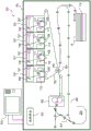
Fig. 1 is a diagram showing an overall view of an image forming apparatus;
fig. 2 is a diagram showing the outer periphery of the turned-over portion;
fig. 3A and 3B are diagrams illustrating the movement of the sheet at the reversing portion;
FIG. 4 is a diagram illustrating accelerated movement of a sheet material;
fig. 5 is a diagram showing a sheet conveyed in the reversing section;
fig. 6A and 6B are graphs showing changes in the guide resistance;
FIG. 7 is a diagram illustrating a warping mechanism;
FIG. 8 is a flowchart showing a transfer operation;
fig. 9 is a table showing conditions under which warpage occurs;
FIG. 10 is a diagram showing an upturned portion configuration having three curved portions;
fig. 11 is a diagram illustrating a configuration of a reversed portion having guide members for guiding the outside and inside of a conveyed sheet.
Detailed Description
Next, a sheet conveying device according to an embodiment of the present invention and an image forming apparatus including the sheet conveying device will be described with reference to the drawings.
{ first embodiment } < general configuration of image forming apparatus >
First, the overall configuration of the image forming apparatus will be described. Fig. 1 is a sectional view showing the configuration of a laser beam printer 100 (hereinafter referred to as a printer) according to the present embodiment. As shown in the figure, the printer 100 has a housing 101, and the housing 101 includes: a mechanism for configuring an engine portion, an engine control portion for performing control of a printing process (e.g., a feeding process) performed by these mechanisms, and a control portion 103 that houses a printer controller.
These mechanisms for configuring the engine portion include an optical processing mechanism, a fixing processing mechanism, a feeding processing mechanism for the sheet P, and a conveying processing mechanism for the sheet P. The optical processing mechanism is for forming an electrostatic latent image on the photosensitive drum 105 by scanning with a laser beam, for visualizing the electrostatic latent image, for multiple-transferring the latent image onto an intermediate transfer body 152 composed of an endless belt, and for further transferring the multiple-transferred color image onto a sheet P. The fixing processing mechanism is used to fix the toner image transferred onto the sheet P.
The optical processing mechanism has a laser driver for turning on and off laser light emitted from a semiconductor laser (not shown) in the laser scanner unit 107 in accordance with image data supplied from the control section 103. A laser beam emitted from a semiconductor laser is oscillated in a scanning direction by a rotating polygon mirror. The laser beam oscillated in the main scanning direction is guided to the photosensitive drum 105 via the reflective polygon mirror 109, and exposes the photosensitive drum 105 in the main scanning direction.
On the other hand, an electrostatic latent image, which is charged by the primary charger 111 and formed on the photosensitive drum 105 by scanning by the laser light, is visualized as a toner image by toner supplied by the developing device 112. Then, the toner image visualized on the photosensitive drum 105 is transferred (primary transfer) onto an intermediate transfer body 152, and a voltage having a polarity opposite to that of the toner image is applied to the intermediate transfer body 152. In forming a color image, respective colors are formed on the intermediate transfer body 152 in order from the Y (yellow) station 120, the M (magenta) station 121, the C (cyan) station 122, and the K (black) station 123, so that a full-color visible image is formed on the intermediate transfer body 152.
Next, the sheet P fed from the sheet stocker 110 is conveyed, and the transfer roller 151 presses the sheet P against the intermediate transfer body 152 in the transfer portion 140. Meanwhile, a bias having a polarity opposite to that of the toner is applied to the transfer roller 151. As a result, the visible image formed on the intermediate transfer body 152 is transferred (secondary transfer) onto the sheet P conveyed in the conveying direction (sub-scanning direction) in synchronization with image formation.
After the secondary transfer, when the sheet passes through the fixing portion 160, the toner transferred onto the sheet P is heated and melted to be fixed as an image on the sheet P. In the case of duplex printing, the sheet P having an image formed on the first surface thereof is conveyed to the reversing section 200, switched back, and introduced again to the transfer unit 140 where the image is formed on the second surface of the sheet P at the transfer unit 140. Thereafter, when the sheet P passes through the fixing unit 160 in the same manner as described above, the toner image on the sheet P is thermally fixed. Then, the sheet P is discharged out of the printer and the printing process is completed.
Various sheets including plain paper, recycled paper, glossy paper, coated paper, thin paper, and thick paper, which are widely used, are used in printers.
< sheet conveying apparatus >
Next, the configuration of the reversing portion 200 as the sheet conveying apparatus of the present embodiment will be described.
Fig. 2 is a diagram showing a schematic view of the periphery of the reversed part 200 viewed from the front of the main body. The upstream conveying path 201 is provided upstream of the reversing portion 200 in the sheet conveying direction (hereinafter, simply referred to as "upstream"), and the downstream conveying path 202 is provided downstream of the reversing portion 200 in the sheet conveying direction (hereinafter, simply referred to as "downstream"). The sheet P is conveyed from the upstream conveying path 201 to the reversing portion 200, and temporarily stopped at the reversing portion 200. After that, the sheet P is switched back and conveyed to the downstream conveying path 202. To switch the conveying path, a rotatable path switching member 231 is used. An inverting roller 230 serving as a conveying member is provided at a position where the upstream conveying path 201 and the downstream conveying path 202 join upstream of the inverting section 200. The turning roller 230 is a conveying roller capable of rotating in forward and reverse directions. When the nipped sheet P is conveyed from the upstream conveying path 201 to the reversing section 200, the reversing roller 230 rotates in one direction, and when the nipped sheet P is conveyed from the reversing section 200 to the downstream conveying path 202, the reversing roller 230 rotates in the reverse direction (the other direction). Therefore, after the sheet P is conveyed from the upstream conveying path 201 to the reversing portion 200 as illustrated in fig. 3A, the conveying direction is changed to the opposite direction, and the sheet P is conveyed from the reversing portion 200 to the downstream conveying path 202 as illustrated in fig. 3B. As a result, when the sheet having the image recorded on the first surface is reversed and the sheet is conveyed to the transfer portion 140 again, the image is recorded on the second surface.
(bending part)
The reversing section 200 is provided with a plurality of curved portions serving as a changing portion that changes the conveying direction by bending the sheet conveyed downstream of the reversing roller 230. In the present embodiment, two bent portions are provided. That is, the first curved portion 203 is disposed at a position close to the reversing roller 230, and the second curved portion 204 is disposed at a position far from the reversing roller 230. By thus providing a plurality of bent portions, the sheet conveyed to the reversing section 200 is bent into a substantially C-shape. Therefore, even if the sheet size is increased, switchback conveyance can be performed without increasing the apparatus size.
Next, each bent portion will be specifically explained. At each bent portion, a guide member 300 for guiding the sheet P is bent. As a result, when the sheet P is bent by the guide of the guide member 300, the sheet P is conveyed while the conveying direction of the sheet P is changed. The first curved portion 203 is disposed on a substantially extending line along the discharge direction of the sheet P from the reversing roller 230 to the reversing portion 200. In the present embodiment, an angle α (see fig. 2) formed between the direction of the sheet P conveyed downward in the substantially vertical direction from the reversing roller 230 and the direction of the sheet P when leaving the first curved portion 203 is in the range of 40 ° to 80 °.
The conveying direction of the sheet P conveyed from the first curved portion 203 is substantially horizontal, and the second curved portion 204 is provided on an extension line in this direction. The direction of the sheet P entering the second curved portion 204 is substantially horizontal. An angle β (see fig. 2) formed between a direction in which the sheet P enters the second curved portion 204 and a direction in which the sheet P is discharged from the second curved portion 204 is in a range of 80 ° to 100 °. Then, the sheet P discharged from the second curved portion 204 is conveyed upward substantially in the vertical direction.
(guide Member)
The guide member 300 constituting the flip part 200 is disposed only at the outside of the flip part 200 and is not disposed at the inside of the flip part 200. That is, the sheet conveying path from the reversing roller 230 to the reversing portion 200 of the second curved portion 204 is constituted by the guide member 300 for guiding one surface of the conveyed sheet. This is because in the case where the guide member is provided in the reversing portion 200, when the sheet P moves from the reversing portion 200 to the downstream conveying path 202 as shown in fig. 3B, there is a fear that the sheet P rubs against the inner guide member, so that the conveying resistance that the sheet P receives from the guide member increases, and a friction trace may remain on the sheet, resulting in an image defect. By arranging the guide member 300 to guide only one surface of the conveyed sheet as in the present embodiment, the above-described problem can be eliminated.
(sheet conveying speed at turning part)
Next, a conveying operation of conveying the sheet P from the fixing device 160 to the reversing portion 200 and discharging the sheet P from the reversing unit 200 will be described.
Fig. 4 is a diagram illustrating the movement of the sheet P when the sheet P passes through the fixing device 160. The sheet P to which the toner image has been transferred by the transfer portion 140 is conveyed through the fixing device 160 at a speed of 400m/s to 500m/s, during which the sheet P is heated and pressurized to fix the toner image on the sheet P. In the case of duplex printing, the sheet is conveyed from the fixing device 160 to the reversing portion 200. At this time, the conveying speed is changed depending on whether the length of the sheet is equal to or greater than a predetermined length.
Here, whether the length of the sheet is equal to or greater than the predetermined length is determined by whether the leading end of the sheet fed by the reversing roller 230 passes through the second curved portion 204. In the present embodiment, when the length in the conveying direction of the sheet P is 500mm or more, the leading edge of the sheet conveyed by the reversing roller 230 passes through the second curved portion, and when the length is less than 500mm, the sheet P is turned back and conveyed to the downstream conveying path 202 before the leading edge of the sheet fed by the reversing roller 230 reaches the second curved portion. Therefore, in the present embodiment, the conveying speed is changed depending on whether or not the length of the sheet in the conveying direction is 500mm or more as a predetermined length.
Specifically, in the case where the length of the sheet in the conveying direction of the sheet P is less than 500mm, the sheet is accelerated to a speed of 1200mm/s to 1500mm/s after passing through the fixing device 160, at which the sheet is conveyed.
The accelerated sheet P is conveyed by the reversing roller 230 at the maintained accelerated speed, and the leading end of the sheet P enters the first bending portion 203 in the reversing portion 200. The sheet P stops before the leading end of the sheet reaches the second curved portion 204. Thereafter, the stopped sheet P is conveyed to the downstream conveying path at a speed of 600mm/s to 800 mm/s.
As described above, by accelerating the sheet P after passing through the fixing device 160, the time required from transferring the toner image to the first surface of the sheet P to transferring the toner image to the second surface of the sheet P can be shortened. As a result, the productivity of the product output from the main body can be increased. However, if the sheet is accelerated while the sheet is in the fixing device 160, the amount of heat given to the sheet P from the fixing device 160 will vary within the surface of the sheet P, resulting in image defects caused by the fixing device. Therefore, it is necessary to perform an acceleration operation of the sheet P after the trailing end of the sheet P passes through the fixing device 160.
On the other hand, in the case of a long sheet having a length of 500mm or more in the conveying direction, when the sheet P is turned back at the reversing portion 200, the leading end of the sheet P reaches the second curved portion 204 and the leading end of the sheet P moves upward in the vertical direction downstream of the second curved portion 204 along the guide member, as shown in fig. 5. As described above, in the case where the sheet is conveyed while being bent by the plurality of bent portions, the following problems may occur.
The first problem is that the conveyance resistance that occurs when the rigidity of the sheet P is high increases.
When the sheet having high rigidity passes through the first curved portion 203 and the second curved portion 204, the resistance received by the sheet P from the guide member 300 also increases. This is because when the length of the sheet is large, the area of the sheet contacting the guide member 300 is also large. Specifically, in the present embodiment, when the sheet P passes through the second curved portion 204, the sheet P travels in the vertical direction while colliding with the second curved portion 204 and the guide member 300 located downstream of the second curved portion 204. Therefore, the resistance received by the sheet P from the guide member 300 temporarily increases.
Fig. 6A is a diagram illustrating resistance received by the sheet P from the guide member 300 when the sheet P passes through the reversing portion 200. The horizontal axis of the graph represents the elapsed time since the sheet P has been discharged from the reversing roller 230 and the vertical axis of the graph represents the resistance received by the sheet P from the guide member 300 at each timing. The unit of the vertical axis is (N/mm), which represents the resistance per 1mm of the sheet P with respect to the front-rear direction of the image forming apparatus main body (i.e., the sheet width direction orthogonal to the sheet conveying direction). K1 in fig. 6A shows the resistance that the sheet P receives from the guide member 300 at the time when the leading end of the sheet P collides with the second curved portion 204. It is confirmed that the resistance force received by the sheet P from the guide member 300 increases at the time when the leading end of the sheet P collides with the second curved portion 204.
When the resistance received by the guide member 300 from the sheet P increases, a defect occurs, which includes a defect in which a driving source (not shown) driving the reversing roller 230 is out of step and stops; a slip occurs between the reversing roller 230 and the sheet P, so that the sheet cannot be conveyed as intended, resulting in a defect of poor conveyance; and a defect that the sheet P is skewed.
The second problem is that when the rigidity of the sheet P is low, the leading edge of the sheet P warps.
Fig. 7 is a diagram illustrating a mechanism of the warpage of the sheet P. This problem occurs when the following expression is satisfied, in which the air resistance received by the leading end of the sheet shown in fig. 7 is given as Fv, in which the force generated due to the gravity of the sheet itself is given as Fg, and the force that retains the shape with the sheet rigidity is given as F.
Fv+Fg>F...(1)
In the present embodiment, as shown in fig. 5, when the sheet conveying direction of the reversing roller 230 is a direction substantially vertically downward, the direction of travel of the leading end of the sheet P passing through the second curved portion 204 is a direction substantially vertically upward. As described above, in the case where the conveying direction of the sheet having passed through the reversing roller 230 and the conveying direction of the sheet having passed through the curved portion are set to be substantially opposite directions, or in the case where the leading end of the sheet is distant from the reversing roller 230, the sheet is easily warped. This is because the shape of the sheet near the reversing roller 230 can be regulated by the roller nip, but the shape of the sheet at a position away from the roller nip cannot be regulated by the roller nip. Specifically, in the present embodiment, the reversing roller 230 feeds the sheet P in a state where the leading end of the sheet P faces downward in the substantially vertical direction, and the sheet that has passed through the second curved portion 204 away from the reversing roller 230 is conveyed upward in the substantially vertical direction. Therefore, the leading end portion of the sheet is not affected by the roller nip of the reversing roller 230, and the shape of the leading end of the sheet is maintained by the rigidity of the sheet itself.
When the rigidity of the sheet P is low, the force F for maintaining the shape of the sheet P with the rigidity is small, so that the shape of the leading end of the sheet P is susceptible to the air resistance Fv and its own weight Fg. As a result, the leading edge of the sheet is likely to warp. In addition, when the leading end of the sheet P is conveyed vertically upward at a position higher by 60mm or more than the bottom surface of the inverting portion 200, a force Fg due to the gravity of the sheet P itself is also increased, and thus warping may occur.
In order to solve the problems of increase in conveyance resistance and easiness of occurrence of warpage, in the present embodiment, the control section 103 controls the speed of a reversing motor (not shown) that drives the reversing roller 230 in accordance with the sheet size so as to suppress occurrence of the above-described problems. Specifically, the control unit 103 controls the conveying speed such that V1< V2, where V1 denotes a conveying speed of a long sheet long enough for the leading end of the sheet conveyed by the reversing roller 230 to pass through the second curved portion 204, and V2 denotes a conveying speed of a short sheet short enough for the sheet to turn back without reaching the second curved portion 204. The control section 103 includes a processor and a memory. The memory stores instructions that, when executed by the processor, cause the imaging device to perform the operations shown in the flowchart of fig. 8.
I.e. as shown in the flow chart of fig. 8. When the sheet size is input from the operation portion 310 (see fig. 1) (step S1) and the image forming operation is started, the sheet conveying operation is started (step S2). Then, the toner image is transferred onto the first surface and the sheet P passes through the fixing device 160. In the case of duplex printing, after the image is fixed, the sheet P is conveyed to the reversing portion 200. At this time, the sheet conveying speed is determined based on the sheet size (step S3). After that, the sheet is conveyed at the reversing portion 200 at the determined speed (step S4).
In the present embodiment, in the case of a long sheet having a length of 500mm or more in the conveying direction, the sheet P is not accelerated after the sheet P has passed through the fixing device 160 at a conveying speed of 400mm/s to 500mm/s at the time of fixing, unlike the case where the length of the sheet P in the conveying direction is less than 500 mm. That is, the leading end of the sheet P enters the reversing section 200 while maintaining the conveying speed of 400mm/s to 500mm/s, and the sheet P is conveyed downstream of the first curved portion 203 and the second curved portion 204. Thereafter, the sheet P is switched back (step S5) and conveyed to the downstream conveying path at a speed of 600mm/S to 800mm/S (step S6).
In this way, when the sheet P is conveyed to the reversing portion 200, the conveying speed V1 of the sheet P having a length of 500mm or more in the conveying direction is smaller than the conveying speed V2 of the sheet P having a length of less than 500mm in the conveying direction (V1< V2). As a result, even if the sheet has high rigidity as described above, two problems including an increase in conveyance resistance and a warp of the thin paper can be prevented.
That is, with respect to the problem of an increase in conveyance resistance of the sheet having high rigidity, by lengthening the time during which the leading edge of the sheet P collides with the second curved portion 204 and travels upward, the impact occurring when the sheet P collides with the second curved portion 204 can be alleviated.
Fig. 6B is a graph showing the torque in the case where the sheet P passes through the second curved portion 204 at a speed of 470 mm/s. The horizontal axis of the graph indicates the elapsed time since the sheet has been discharged from the reversing roller 230, and the vertical axis of the graph indicates the resistance received by the sheet P from the guide member at each timing.
At K2 in fig. 6B, the sheet P collides with the second curved portion 204, but the increase in temporary resistance existing at K1 in fig. 6A disappears at K2 in fig. 6B. By reducing the conveying speed of the sheet P when passing through the second curved portion as described above, the resistance that the sheet P receives from the guide member 300 can be reduced.
Further, by reducing the conveying speed at the second curved portion 204 and the guide member 300 located downstream of the second curved portion 204, it is possible to prevent the problem of warping of the sheet having low rigidity.
As shown in the above equation (1), when the sum of the air resistance Fv and the gravity Fg of the sheet itself is larger than the force F for maintaining its shape with the stiffness of the sheet, warping occurs.
It is known that when the conveying speed is v, the air resistance Fv is expressed by the following equation (k is a constant).
Fv=k×v...(2)
Therefore, by decreasing the conveying speed v, the air resistance Fv decreases. As a result, expression (1) is not satisfied, so that the sheet can be prevented from warping. Fig. 9 is a table showing the sheet conveying speed and the presence or absence of warp in the reversing portion 200. From the table, it can be seen that the sheet can be prevented from warping by setting the sheet conveying speed to 600mm/s or less in the reversing section 200.
Incidentally, as described above, in the present embodiment, the guide member 300 is disposed only on the outer side of the turnover part 200. It is also conceivable to provide a guide member inside the reversing portion 200 to regulate the shape of the leading end of the sheet P between the outer guide member and the inner guide member (prevent buckling). However, in the present embodiment, the warp can be sufficiently prevented by reducing the sheet conveying speed v. As a result, such an internal guide member does not need to be provided.
As described above, by changing the conveying speed of the sheet P in accordance with the length of the sheet, it is possible to prevent problems including an increase in conveying force and a warp of the sheet having low rigidity in the sheet having high rigidity when the length of the sheet P is large.
(multiple curved portions)
In the present embodiment, as described above, two curved portions including the first curved portion 203 and the second curved portion 204 are provided in the flip portion 200. However, three or more bending portions may be arranged in the reversing portion 200 so that the sheet is bent and conveyed by the three or more bending portions.
For example, as shown in fig. 10, the third curved portion 213 may be disposed downstream of the first curved portion 211 and the second curved portion 212. With this configuration, the sheet conveyed by the reversing portion 200 is gently bent, which enables the sheet P to be conveyed more smoothly. In the above-described embodiment, whether the conveying speed of the sheet is changed is determined based on whether the leading end of the sheet to be reversed passes through the second curved portion 204. That is, the second curved portion from the reversing roller 230 is used as a specific curved portion serving as a reference for changing the sheet conveying speed. However, the third curved portion 213, which is the third curved portion from the reversing roller 230, may also be used as a specific curved portion serving as a reference for changing the sheet conveying speed.
That is, in the case of a sheet having high rigidity, when the sheet is conveyed to the downstream of a specific curved portion serving as a reference for changing the sheet conveying speed, the conveying resistance of the guide member 300 becomes high, which may cause a conveyance failure. Further, in the case of a sheet having low rigidity, when warpage is easily generated, a bent portion is selected as a specific bent portion. When the sheet conveyed to the reversing portion 200 in the conveying direction has a length in the sheet conveying direction such that the sheet is conveyed downstream of the specific curved portion, the conveying speed is lower than that of a sheet that is not conveyed to the specific curved portion. As a result, the sheet can be conveyed without causing a sheet conveyance failure in the reversing portion.
{ second embodiment }
In the first embodiment described above, the guide member 300 for guiding the sheet conveyed through the reversing portion 200 has a configuration of guiding one surface (outer side) of the sheet. However, as shown in fig. 11, as a guide member for guiding the sheet conveyed through the reversing portion 200, a guide member 301 for guiding the inner side of the sheet may be provided in addition to the guide member 300 for guiding the outer side of the sheet.
By providing the guide member 301 on the inner side, there is a fear that the resistance that the sheet P receives from the guide member 301 when the sheet P is switched back and moved from the reversing portion 200 to the downstream conveying path 202 increases. However, since the shape of the leading end of the sheet P can be regulated to some extent by the internal guide member 301, warping of the sheet having low rigidity is unlikely to occur.
While the present invention has been described with reference to exemplary embodiments, it is to be understood that the invention is not limited to the disclosed exemplary embodiments. The scope of the following claims is to be accorded the broadest interpretation so as to encompass all such modifications and equivalent structures and functions.
This application claims the benefit of japanese patent application No.2017-085129, filed 24.4.2017, the entire contents of which are hereby incorporated by reference.
Claims (14)
1. A sheet conveying apparatus, comprising:
a conveying member configured to convey a sheet;
a first changing portion configured to change a conveying direction of the sheet conveyed by the conveying member by bending the sheet;
a second changing portion configured to change the conveying direction of the sheet, the conveying direction of which has been changed by the first changing portion, by bending the sheet; and
a control portion configured to control a conveying speed of the sheet,
wherein the conveying member conveys the sheet by rotating in a first direction such that a leading edge of the sheet moves to the first changing portion, and a conveying direction of the sheet conveyed by the conveying member rotating in the first direction is changed by the first changing portion,
wherein, in a case where the sheet is conveyed by the conveying member rotating in the first direction, the conveying direction of the sheet that has been changed by the first changing portion is changed by the second changing portion,
wherein the conveying member conveys the sheet by rotating in a second rotating direction opposite to the first direction after rotating in the first direction, and
wherein the control portion controls a conveying speed of the sheet so that: (i) in the case of conveying the first sheet, the conveying speed V1 is set as the conveying speed of the first sheet on the conveying member rotating in the first direction at least when the leading edge of the first sheet contacts the second changing portion; and (ii) in a case where a second sheet shorter than the first sheet is conveyed, a conveying speed V2 which is faster than the conveying speed V1 is set as a conveying speed of the second sheet on a conveying member rotating in the first direction at least when a leading edge of the second sheet contacts the first changed portion, and the second sheet does not reach the second changed portion when conveyed by the conveying member rotating in the first direction.
2. The sheet conveying apparatus according to claim 1,
wherein the control portion sets the conveying speed of the first sheet on the conveying member rotating in the first direction to the conveying speed V1 when the leading edge of the first sheet conveyed by the conveying member rotating in the first direction contacts the first changing portion and the leading edge of the first sheet conveyed by the conveying member rotating in the first direction contacts the second changing portion.
3. The sheet conveying apparatus according to claim 1,
wherein, when the first sheet is conveyed by the conveying member rotating in the second direction and the second sheet is conveyed by the conveying member rotating in the second direction, the control portion sets the conveying speed of the sheet on the conveying member rotating in the first direction to the conveying speed V3.
4. The sheet conveying apparatus according to claim 1,
wherein it is determined by the control portion whether the sheet will reach the second changing portion based on a length of the sheet in a conveying direction of the sheet.
5. The sheet conveying apparatus according to claim 1,
wherein the advancing direction of the leading edge of the sheet from the conveying member to the first changing portion and the advancing direction of the leading edge of the sheet that has been changed by the second changing portion are substantially opposite to each other.
6. The sheet conveying apparatus according to claim 1,
wherein the second changing portion changes to the sheet conveying direction substantially in the vertically upward direction.
7. The sheet conveying apparatus according to claim 1,
wherein the first changing portion includes a guide member for guiding the sheet and the second changing portion includes an additional guide member for guiding the sheet.
8. The sheet conveying apparatus according to claim 1,
wherein a sheet conveying path from the conveying member to the second changing portion includes a guide member for guiding one surface of the conveyed sheet.
9. The sheet conveying apparatus according to claim 1, wherein in a case where the first sheet is conveyed by the conveying member rotating in the first direction, the control portion sets a conveying speed from when a leading edge of the first sheet contacts the second changing portion until when the first sheet is stopped as a conveying speed V1.
10. A sheet conveying apparatus comprising:
a conveying roller configured to convey a sheet;
a control section configured to control the conveying roller;
a first bending portion configured to bend the sheet conveyed by the conveying roller by contacting the sheet; and
a second bending portion provided at a position different from the first bending portion and configured to bend the sheet by contacting the sheet that has been bent by the first bending portion,
wherein the conveying roller is configured to convey the sheet by rotating the conveying roller in one direction such that a leading edge of the sheet is conveyed toward the first curved portion and thereafter switch back and convey the sheet by rotating the conveying roller in another direction,
wherein the control section controls the conveying roller such that, when the first sheet is conveyed, the first sheet is conveyed at a first speed by rotating the conveying roller in the one direction, and when a second sheet whose length in the conveying direction is smaller than that of the first sheet is conveyed, the second sheet is conveyed at a second speed larger than the first speed by rotating the conveying roller in the one direction,
wherein, when the first sheet is conveyed by a conveying roller rotating in the one direction, the first sheet reaches the first curved portion and the second curved portion, and
wherein, in a case where the second sheet is conveyed by the conveying roller rotating in the one direction, the second sheet reaches the first curved portion without reaching the second curved portion.
11. The sheet conveying apparatus according to claim 10,
wherein the conveying roller is configured to convey a sheet downward,
wherein the first bending portion is configured to bend the sheet conveyed by the conveying roller such that a leading edge of the sheet is directed in a substantially horizontal direction, and
wherein the second bending portion is configured to bend the sheet conveyed by the conveying roller such that a leading edge of the sheet is directed in an upward direction.
12. The sheet conveying apparatus according to claim 10,
wherein the second bending portion is configured to bend the sheet conveyed by the rotation of the conveying roller in the one direction such that the direction of the leading edge of the sheet is changed from the substantially horizontal direction to the substantially vertically upward direction.
13. The sheet conveying apparatus according to claim 10,
wherein a leading edge of the sheet bent by the second bent portion is directed in a substantially vertically upward direction.
14. An image forming apparatus comprising:
an image forming portion configured to form an image on a sheet;
a conveying member configured to convey a sheet;
a first changing portion configured to change a conveying direction of the sheet conveyed by the conveying member by bending the sheet;
a second changing portion configured to change the conveying direction of the sheet, the conveying direction of which has been changed by the first changing portion, by bending the sheet; and
a control portion configured to control a conveying speed of the sheet,
wherein the conveying member conveys the sheet by rotating in a first direction such that a leading edge of the sheet moves to the first changing portion, and a conveying direction of the sheet conveyed by the conveying member rotating in the first direction is changed by the first changing portion,
wherein, in a case where the sheet is conveyed by the conveying member rotating in the first direction, the conveying direction of the sheet that has been changed by the first changing portion is changed by the second changing portion,
wherein the conveying member conveys the sheet by rotating in a second rotating direction opposite to the first direction after rotating in the first direction, and
wherein the control portion controls the conveying speed of the sheet such that (i) in a case where the first sheet is conveyed, the conveying speed V1 is set as a conveying speed of the first sheet on the conveying member rotating in the first direction at least when the leading edge of the first sheet contacts the second changing portion; and (ii) in a case where a second sheet shorter than the first sheet is conveyed, a conveying speed V2 which is faster than the conveying speed V1 is set as a conveying speed of the second sheet on a conveying member rotating in the first direction at least when a leading edge of the second sheet contacts the first changed portion, and the second sheet does not reach the second changed portion when conveyed by the conveying member rotating in the first direction.
Applications Claiming Priority (2)
| Application Number | Priority Date | Filing Date | Title |
|---|---|---|---|
| JP2017-085129 | 2017-04-24 | ||
| JP2017085129A JP6929690B2 (en) | 2017-04-24 | 2017-04-24 | Sheet transfer device and image forming device |
Publications (2)
| Publication Number | Publication Date |
|---|---|
| CN108732888A CN108732888A (en) | 2018-11-02 |
| CN108732888B true CN108732888B (en) | 2021-10-01 |
Family
ID=63852693
Family Applications (1)
| Application Number | Title | Priority Date | Filing Date |
|---|---|---|---|
| CN201810364060.XA Active CN108732888B (en) | 2017-04-24 | 2018-04-23 | Sheet conveying apparatus and image forming apparatus |
Country Status (3)
| Country | Link |
|---|---|
| US (1) | US10577205B2 (en) |
| JP (1) | JP6929690B2 (en) |
| CN (1) | CN108732888B (en) |
Families Citing this family (5)
| Publication number | Priority date | Publication date | Assignee | Title |
|---|---|---|---|---|
| US10754279B2 (en) | 2018-08-31 | 2020-08-25 | Canon Kabushiki Kaisha | Image forming apparatus having air blowing on a sheet |
| US11548757B2 (en) | 2019-07-12 | 2023-01-10 | Canon Kabushiki Kaisha | Image forming apparatus |
| JP7451104B2 (en) | 2019-08-01 | 2024-03-18 | キヤノン株式会社 | Image forming device |
| JP2022013059A (en) * | 2020-07-03 | 2022-01-18 | キヤノン株式会社 | Image forming apparatus |
| JP2022133160A (en) * | 2021-03-01 | 2022-09-13 | キヤノン株式会社 | Image forming apparatus |
Citations (3)
| Publication number | Priority date | Publication date | Assignee | Title |
|---|---|---|---|---|
| US6419222B1 (en) * | 2000-12-12 | 2002-07-16 | Xerox Corporation | Sheet inverting apparatus and method |
| CN101359193A (en) * | 2007-07-31 | 2009-02-04 | 佳能株式会社 | Sheet conveying apparatus and image forming apparatus |
| CN105565019A (en) * | 2014-11-04 | 2016-05-11 | 富士施乐株式会社 | Sheet transport device and image forming system |
Family Cites Families (9)
| Publication number | Priority date | Publication date | Assignee | Title |
|---|---|---|---|---|
| US6626428B2 (en) * | 2001-12-28 | 2003-09-30 | Kabushiki Kaisha Toshiba | Sheet ejection mechanism |
| JP2003201069A (en) * | 2002-01-10 | 2003-07-15 | Canon Inc | Image forming device |
| JP4691677B2 (en) * | 2005-08-03 | 2011-06-01 | コニカミノルタビジネステクノロジーズ株式会社 | Image forming apparatus and re-conveying speed setting program for image forming apparatus |
| JP5084411B2 (en) * | 2007-09-07 | 2012-11-28 | デュプロ精工株式会社 | Paper reversing device |
| JP5219492B2 (en) * | 2007-12-19 | 2013-06-26 | キヤノン株式会社 | Sheet conveying apparatus and image forming apparatus |
| JP5202406B2 (en) * | 2009-03-19 | 2013-06-05 | キヤノン株式会社 | Image forming apparatus |
| JP5488790B2 (en) * | 2009-05-20 | 2014-05-14 | セイコーエプソン株式会社 | Recording device |
| JP5416628B2 (en) * | 2010-03-18 | 2014-02-12 | 株式会社沖データ | Document conveying apparatus, image reading apparatus, and image forming apparatus |
| JP2015025911A (en) * | 2013-07-25 | 2015-02-05 | 株式会社沖データ | Image forming apparatus |
-
2017
- 2017-04-24 JP JP2017085129A patent/JP6929690B2/en active Active
-
2018
- 2018-04-17 US US15/954,988 patent/US10577205B2/en active Active
- 2018-04-23 CN CN201810364060.XA patent/CN108732888B/en active Active
Patent Citations (3)
| Publication number | Priority date | Publication date | Assignee | Title |
|---|---|---|---|---|
| US6419222B1 (en) * | 2000-12-12 | 2002-07-16 | Xerox Corporation | Sheet inverting apparatus and method |
| CN101359193A (en) * | 2007-07-31 | 2009-02-04 | 佳能株式会社 | Sheet conveying apparatus and image forming apparatus |
| CN105565019A (en) * | 2014-11-04 | 2016-05-11 | 富士施乐株式会社 | Sheet transport device and image forming system |
Also Published As
| Publication number | Publication date |
|---|---|
| JP2018184228A (en) | 2018-11-22 |
| JP6929690B2 (en) | 2021-09-01 |
| CN108732888A (en) | 2018-11-02 |
| US20180305153A1 (en) | 2018-10-25 |
| US10577205B2 (en) | 2020-03-03 |
Similar Documents
| Publication | Publication Date | Title |
|---|---|---|
| CN108732888B (en) | Sheet conveying apparatus and image forming apparatus | |
| CN108732889B (en) | Sheet conveying device and image forming apparatus | |
| JP5087948B2 (en) | Image forming apparatus capable of duplex recording | |
| EP3588198B1 (en) | Image forming apparatus | |
| JP2007197105A (en) | Image forming device | |
| CN111308869A (en) | Sheet conveying apparatus and image forming apparatus | |
| JP4857662B2 (en) | Image forming apparatus and image forming apparatus control method | |
| US11319178B2 (en) | Sheet conveyance apparatus and image forming apparatus | |
| JP7451104B2 (en) | Image forming device | |
| JP6493129B2 (en) | Image forming apparatus | |
| JP2013242362A (en) | Image forming apparatus | |
| US11866287B2 (en) | Sheet feeding device and an image forming apparatus with a sheet feeding device | |
| JP4950654B2 (en) | Image forming apparatus | |
| JP7321719B2 (en) | image forming device | |
| JP6204307B2 (en) | Image forming apparatus | |
| JP5538912B2 (en) | Sheet reversing apparatus and image forming apparatus | |
| JP2019142629A (en) | Image forming apparatus | |
| JP7327989B2 (en) | image forming device | |
| US20240012355A1 (en) | Image forming apparatus | |
| JP2018058670A (en) | Sheet conveyance apparatus, sheet processing apparatus and image forming apparatus | |
| KR20230117702A (en) | Conveyance apparatus and image forming apparatus | |
| JP2012185456A (en) | Transfer device and image forming apparatus | |
| JP2010100403A (en) | Sheet carrying device and image forming device | |
| JP2012185455A (en) | Transfer device and image forming apparatus | |
| JP2012254885A (en) | Image forming apparatus |
Legal Events
| Date | Code | Title | Description |
|---|---|---|---|
| PB01 | Publication | ||
| PB01 | Publication | ||
| SE01 | Entry into force of request for substantive examination | ||
| SE01 | Entry into force of request for substantive examination | ||
| GR01 | Patent grant | ||
| GR01 | Patent grant |