JP5317844B2 - Discharge device - Google Patents
Discharge device Download PDFInfo
- Publication number
- JP5317844B2 JP5317844B2 JP2009144129A JP2009144129A JP5317844B2 JP 5317844 B2 JP5317844 B2 JP 5317844B2 JP 2009144129 A JP2009144129 A JP 2009144129A JP 2009144129 A JP2009144129 A JP 2009144129A JP 5317844 B2 JP5317844 B2 JP 5317844B2
- Authority
- JP
- Japan
- Prior art keywords
- substrate
- camera
- moving
- head
- discharge
- Prior art date
- Legal status (The legal status is an assumption and is not a legal conclusion. Google has not performed a legal analysis and makes no representation as to the accuracy of the status listed.)
- Expired - Fee Related
Links
- 239000000758 substrate Substances 0.000 claims abstract description 131
- 238000000034 method Methods 0.000 claims abstract description 17
- NJPPVKZQTLUDBO-UHFFFAOYSA-N novaluron Chemical compound C1=C(Cl)C(OC(F)(F)C(OC(F)(F)F)F)=CC=C1NC(=O)NC(=O)C1=C(F)C=CC=C1F NJPPVKZQTLUDBO-UHFFFAOYSA-N 0.000 claims description 18
- 238000012545 processing Methods 0.000 claims description 9
- 239000007788 liquid Substances 0.000 claims description 5
- 238000005259 measurement Methods 0.000 claims description 5
- 239000000976 ink Substances 0.000 description 23
- 239000003086 colorant Substances 0.000 description 4
- 238000013461 design Methods 0.000 description 4
- 238000010586 diagram Methods 0.000 description 4
- 239000004973 liquid crystal related substance Substances 0.000 description 3
- 238000004519 manufacturing process Methods 0.000 description 3
- 238000003491 array Methods 0.000 description 2
- 238000001035 drying Methods 0.000 description 2
- 239000011159 matrix material Substances 0.000 description 2
- 238000011161 development Methods 0.000 description 1
- 238000005401 electroluminescence Methods 0.000 description 1
- 238000001179 sorption measurement Methods 0.000 description 1
Images


Abstract
Description
本発明は、吐出装置の位置合わせ方法に関する。 The present invention relates to an alignment method for a discharge device.
近年の情報化社会の伸展に伴い、より大型の液晶表示装置の需要が高まり、その生産性の向上が望まれている。カラー液晶表示装置では、表示画像をカラー化するためにカラーフィルターを用いている。カラーフィルターは、基板上の所定の領域に、R(赤)、G(緑)、B(青)の3色のインクを所定のパターンで配置することにより作成される。 With the development of the information society in recent years, the demand for larger liquid crystal display devices has increased, and improvement in productivity has been desired. In a color liquid crystal display device, a color filter is used to color a display image. The color filter is created by arranging inks of three colors R (red), G (green), and B (blue) in a predetermined pattern on a predetermined region on the substrate.
従来、多くの吐出装置は、水平な基準面に静置された台座と、台座上に配置され基板を保持する基板移動部と、台座上に配置されヘッドが取り付けられたヘッド保持部とを有している。
特許文献1記載の装置では、ヘッド保持部を基板上を走査するように往復移動させて吐出する方式を採用しているが、この方式では基板の大型化に比例してインクの吐出に長い時間がかかり、また、ムラなく所定の間隔でインクを着弾させるにはインクヘッドの難しい制御が必要であった。
Conventionally, many ejection devices have a pedestal that is stationary on a horizontal reference surface, a substrate moving unit that is disposed on the pedestal and holds a substrate, and a head holding unit that is disposed on the pedestal and has a head attached thereto. doing.
The apparatus described in
上記方式に対し、特許文献2記載の装置では、台座に対して静止したヘッド保持部が多数のヘッドを保持して、その下を通過する基板にインクを吐出する方式を採用しており、上記の課題を解決している。この方式では、基板上の所定の位置に所定の吐出口を配置するには、基板の移動前に基板とヘッドの位置を正確に認識し、また基板の移動方向以外のズレを修正する位置合わせが必要である。 In contrast to the above method, the apparatus described in Patent Document 2 employs a method in which a head holding unit that is stationary with respect to a pedestal holds a number of heads and discharges ink onto a substrate that passes under the head. The problem is solved. In this method, in order to place a predetermined discharge port at a predetermined position on the substrate, the position of the substrate and the head is accurately recognized before the substrate is moved, and alignment is performed to correct a deviation other than the moving direction of the substrate. is necessary.
特許文献2記載の装置では、基板位置の認識とヘッドの認識の両方を、台座に固定された固定カメラで行うので、位置合わせの際にヘッド保持部を固定カメラ上に移動させる必要がある。ヘッド保持部の保持するヘッドの数が増え、ヘッド保持部が大型化するにつれて、ヘッド保持部の移動が不安定になるという不都合があった。 In the apparatus described in Patent Document 2, since both the substrate position recognition and the head recognition are performed by a fixed camera fixed to a pedestal, it is necessary to move the head holding unit onto the fixed camera at the time of alignment. As the number of heads held by the head holding unit increases and the size of the head holding unit increases, the movement of the head holding unit becomes unstable.
本発明は上記従来技術の不都合を解決するために創作されたものであり、その目的は、基板を多数のヘッドを保持するヘッド保持部の下を通過させてインクを吐出する吐出装置において、着弾位置と吐出口の位置合わせ方法を提供することにある。 The present invention was created to solve the above-described disadvantages of the prior art, and an object of the present invention is to provide a landing device in an ejection device that ejects ink by passing a substrate under a head holding portion that holds a number of heads. An object of the present invention is to provide a method for aligning a position and a discharge port.
上記課題を解決するために本発明は、吐出装置であって、基準面に対して静置された台座と、前記台座に固定されたヘッド保持部と、前記ヘッド保持部に保持された複数のヘッドと、各前記ヘッドに設けられた複数の吐出口と、前記台座に対し、前記基準面に平行な第一の方向に移動可能な基板移動部と、を有し、前記吐出口から前記基板移動部上に配置された基板の着弾位置に向かって前記吐出液を吐出し、前記吐出液の液滴を前記基板上に着弾させる吐出装置であって、前記ヘッド保持部に固定され、前記基板の複数の基板基準点を撮影する複数の固定カメラと、前記基板移動部上で前記基板を前記基準面に平行に回転移動する基板回転機構と、カメラで撮影された画像を処理する処理機能を有する制御装置と、前記基板移動部に設置され、前記基板移動部に対し、前記基準面に平行で前記第一の方向に垂直な第二の方向に移動可能で、前記ヘッドを撮影可能な移動カメラと、前記基板移動部の、前記第一、第二の方向の移動量と移動方向とを測定する測定装置と、前記複数のヘッドを一体として前記第二の方向に移動可能なヘッド移動機構を有し、前記複数の固定カメラは、前記第二の方向に離間して設置され、複数の前記基板基準点と各前記着弾位置との相対位置は予め設定されており、前記制御装置は、前記基板移動部を移動させ、前記移動カメラで、各前記固定カメラのレンズをそれぞれ撮影し、前記測定装置の測定値から各前記固定カメラのカメラ基準点の位置を求め、複数の前記基板基準点を前記固定カメラで撮影し、前記基板基準点を結ぶ線分の前記第二の方向に対する傾きを求め、前記移動カメラによって前記吐出口を撮影し、前記吐出口の位置を求め、前記傾きを修正するように前記基板回転機構を制御して前記基板移動部を回転させ、求められた前記吐出口の位置から、前記ヘッド移動機構によって複数の前記ヘッドを前記第二の方向に移動させ、各前記吐出口の前記第二の方向上の位置が、前記液滴を吐出すべき前記着弾位置の前記第二の方向上の位置に対して、所定の範囲内に位置させるように構成された吐出装置である。
本発明は吐出装置であって、前記固定カメラの前記レンズには、前記カメラ基準点の前記第一、第二の方向上の位置にマークが設けられており、前記制御装置は、前記移動カメラによって前記マークを撮影して前記カメラ基準点の位置を求めて前記固定カメラの位置を求めるようにされた吐出装置である。
本発明は吐出装置であって、前記複数のヘッドを個別に移動可能な個別ヘッド位置修正手段を有し、前記制御装置は、前記移動カメラの画像を処理して前記ヘッドの位置を検出し、複数の前記ヘッドの相互の位置が既定の範囲内になるように前記個別ヘッド位置修正手段を制御する吐出装置である。
In order to solve the above-described problem, the present invention provides a discharge device, a pedestal placed stationary with respect to a reference surface, a head holding unit fixed to the pedestal, and a plurality of holding units held by the head holding unit. A head, a plurality of ejection openings provided in each of the heads, and a substrate moving section that is movable in a first direction parallel to the reference plane with respect to the pedestal, and from the ejection openings to the substrate An ejection device that ejects the ejection liquid toward a landing position of a substrate disposed on a moving unit and deposits droplets of the ejection liquid on the substrate, the ejection device being fixed to the head holding unit, and the substrate A plurality of fixed cameras for photographing a plurality of substrate reference points, a substrate rotating mechanism for rotating the substrate in parallel with the reference plane on the substrate moving unit, and a processing function for processing an image photographed by the camera. a controller having, disposed of in the substrate moving portion , A movable camera capable of moving in a second direction parallel to the reference plane and perpendicular to the first direction with respect to the substrate moving unit, and capable of photographing the head, and the first of the substrate moving unit a measuring device for measuring a movement direction and a movement amount of the second direction includes the second head moving mechanism capable of moving in the direction integrally the plurality of heads, said plurality of fixed cameras, wherein The plurality of substrate reference points and the relative positions of the landing positions are set in advance, and the control device moves the substrate moving unit, and moves the substrate with the moving camera. Photographing the lens of each fixed camera, obtaining the position of the camera reference point of each fixed camera from the measurement value of the measuring device, photographing a plurality of the substrate reference points with the fixed camera, and the substrate reference point The second direction of the line segment connecting Obtains an inclination against, the discharge port taken by the moving camera, obtains the position of the discharge port, prior SL controls the substrate rotating mechanism so as to correct the inclination by rotating the substrate moving part, prompted Further, the plurality of heads are moved in the second direction by the head moving mechanism from the position of the discharge port, and the position of the discharge port in the second direction is to discharge the droplet. The ejection device is configured to be positioned within a predetermined range with respect to the position of the landing position in the second direction .
The present invention is an ejection device, wherein the lens of the fixed camera is provided with a mark at a position in the first and second directions of the camera reference point, and the control device includes the moving camera The discharge device is configured to obtain the position of the fixed camera by photographing the mark by the above and obtaining the position of the camera reference point.
The present invention is an ejection device, comprising individual head position correcting means capable of individually moving the plurality of heads, and the control device detects the position of the head by processing an image of the moving camera, The ejection device controls the individual head position correcting means so that the mutual positions of the plurality of heads are within a predetermined range.
第二の方向の移動手段をヘッド保持部に配置することにより、基板移動部は第二の方向の位置合わせ機構が不要となり、振動に強く、基板の保持が安定する。
ヘッドの位置を静止させた状態でインクの吐出を行うので、ヘッドの位置精度を保つことができる。
ヘッド保持部の移動は、位置合わせのために基板の大きさに比べて微少な距離を移動するだけなので、ヘッド保持部の保持するヘッド数が増えても、ヘッド保持部の移動が不安定になりにくい。
静止した複数のヘッドを使用して、短時間で塗布することで、乾燥ムラがなく、高速でプリントできる。
By disposing the moving means in the second direction on the head holding portion, the substrate moving portion does not need the alignment mechanism in the second direction, is resistant to vibration, and the holding of the substrate is stable.
Since ink is ejected with the head position stationary, the head position accuracy can be maintained.
The head holder moves only a small distance compared to the size of the substrate for alignment, so even if the number of heads held by the head holder increases, the movement of the head holder becomes unstable. Hard to become.
By using a plurality of stationary heads and applying in a short time, printing can be performed at high speed without drying unevenness.
吐出装置をRGBカラーフィルターの製造で使用する場合を一例として説明する。
<吐出装置の構造>
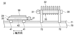
図1は本発明で用いる吐出装置10の側面図を示しており、図2は平面図を示している。
A case where the discharge device is used for manufacturing an RGB color filter will be described as an example.
<Discharge device structure>
FIG. 1 shows a side view of a
吐出装置10は、水平な基準面に対して静置された台座70と、長いレール71と、基板移動部20と、ヘッド保持部30を有している。レール71は台座70上に、その上面が水平になるように、配置されている。基板移動部20はレール71上に配置されている。ヘッド保持部30は、台座70に固定された支柱72に支えられて、レール71上の基板移動部20の高さより高い位置に固定されている。
The
基板移動部20はレール上移動機構41を有している。基板移動部20はレール上移動機構41上に配置される。
レール上移動機構41は、制御装置92から伝送される信号を受けて、基板移動部20をレール71上で移動させる。レール上移動機構41には例えばモーターが用いられる。
基板移動部20はレール71上を移動することにより、ヘッド保持部30の下を往復移動することができるように構成されている。
The
The on-
The
以後、レール71に沿って移動する基板移動部20の移動方向(第一の方向)をy軸方向、それと垂直な水平方向(第二の方向)をx軸方向と呼ぶ。
ヘッド保持部30は、取付板33と、取付板33に取り付けられた複数のヘッド32を有している。
Hereinafter, the moving direction (first direction) of the
The
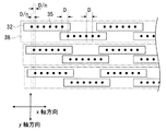
図4はヘッド32と吐出口35の配置を説明する模式図である。
各ヘッド32は、吐出口35を複数有している。一個のヘッド32の複数の吐出口35は、そのヘッド32の一面に、一列に並んで吐出口列を形成し、又は、互いに平行な複数列に並んで、互いに平行な複数の吐出口列を形成している。
一個のヘッド32中の吐出口35は一の方向に等間隔で配置されており、その間隔を吐出口間隔(吐出口の中心間距離)Dとすると、各ヘッド32の吐出口間隔D同士も同じ値にされている。
FIG. 4 is a schematic diagram for explaining the arrangement of the
Each
The
本発明では、一個のヘッド32の複数の吐出口35が、一の方向に等間隔で配置されている限りでは、必ずしも一直線上に並ぶ必要はなく、例えば図5に示すように千鳥配列に並んで、一吐出口列を形成してもよい。
ここでは、各ヘッド32は、前記一の方向がx軸方向と平行になるような向きで取付板33に取り付けられている。
In the present invention, as long as the plurality of
Here, each
各ヘッド32は、ヘッドの前記一の方向の長さが、吐出口列の長さ(端部の吐出口の中心間の前記一の方向の距離)に吐出口間隔Dを加算した長さよりも大きく形成されており、従って、複数のヘッド32をx軸と平行な一列に並べ、y軸上の位置を同一にすると、一のヘッドの吐出口列端部に位置する吐出口と、隣接するヘッドの吐出口列端部に位置する吐出口の間のx軸方向の距離は、吐出口間隔Dよりも大きな距離で離間してしまう。
In each
本発明では、x軸方向に沿って並ぶ複数のヘッド32が、異なるヘッドの端部の吐出口間でもx軸方向の距離が吐出口間隔Dになるように、隣接するヘッドの吐出口35はy軸上では異なる位置に配置されており、隣接するヘッドの端部がx軸上で重なって、異なるヘッドの吐出口間を含めて、各吐出口35がx軸上で吐出口間隔Dで並ぶように配置されている。
In the present invention, the
この場合、x軸に沿って並ぶ複数のヘッド32の吐出口35は、y軸上で二種類の位置に配置することができ、隣接するヘッド32の吐出口列が、二種類の位置に交互に配置されると、そのように配置された一組の複数のヘッド32は、千鳥配列され、1つのヘッド組38を構成する。
In this case, the
ヘッド組38は、複数の組が取付板33に配置されている。
所定の数nのヘッド組38はヘッドグループを構成し、1個のヘッドグループ中では、1つのヘッド組中の隣接する2個の吐出口35の間に、他のヘッド組の吐出口35が、x軸方向に等間隔D/nになるように1個ずつ配置されている。
A plurality of sets of
A predetermined number n of
ヘッド保持部30は不図示のインクタンクを有し、各インクタンクにはR、G、Bの3色のうちの一色のインクが貯蔵されている。各ヘッド32はインクタンクに接続されている。
各吐出口35はそれぞれ内部にインク(吐出液)の詰まったインク室を有し、各インク室には圧力発生装置がそれぞれ配置される。各圧力発生装置は外部の制御装置92から電送される信号を受けて、インク室に所定の圧力を発生させ、吐出口35から所定の量のインクを吐出させる。
The
Each
ヘッド保持部30が3個以上のヘッドグループを有する場合は、各ヘッド32がヘッドグループ毎に異なる色のインクタンクに接続されることにより、1つのヘッド保持部30は3色のインクを吐出できる。
When the
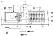
基板移動部20は基板吸着板24を有している。基板吸着板24は基板移動部20上に配置される。
基板吸着板24の上方を向いた面は不図示の吸引口を有し、吸引口は不図示の真空ポンプに接続されている。基板50を基板吸着板24上に配置したのち、真空ポンプで排気を行うと、基板50は基板吸着板24上に真空吸着されて保持される。
The
The surface of the
基板50上には、R、G、Bの各色が着弾されるべき領域(着弾位置)が定められている。基板50は移動方向に対して垂直な方向と平行な方向に格子状のブラックマトリクスを有し、各着弾位置はブラックマトリクスで区画された領域に配置されている。
On the
一枚の基板50上の着弾位置の移動方向と垂直な方向の並びの両端にそれぞれ位置する着弾位置の中心間の距離は、1個のヘッドグループ中の吐出口列の両端にそれぞれ位置する吐出口35の中心間のx軸方向の距離以下に形成されている。
基板50の移動方向と垂直な水平方向に隣り合う着弾位置の間隔は、1個のヘッドグループ中のx軸方向に隣接する吐出口間隔D/nと同じ、又はx軸方向に隣接する吐出口間隔D/nの整数倍の長さに形成されている。
The distance between the centers of the landing positions located at both ends of the arrangement in the direction perpendicular to the moving direction of the landing positions on one
The interval between the landing positions adjacent to each other in the horizontal direction perpendicular to the moving direction of the
<インクの吐出工程>
基板上へのインクの吐出工程を説明する。
後述する第一の位置合わせ工程での位置合わせ作業により、複数のヘッド32は台座70上の座標に対して予め位置合わせがされているものとする。台座70上の座標に対して位置合わせされた複数のヘッド32をまとめて、以後ヘッドアレイと呼ぶ。
<Ink ejection process>
An ink ejection process on the substrate will be described.
It is assumed that the plurality of
先ず、基板移動部20を移動開始位置に移動させて静止させる。基板吸着板24上に、基板50の有する2つの基板基準点51を結ぶ線分がx軸方向に概略沿うような向きで基板50を載せ、真空吸着して基板50を基板吸着板24上に吸着保持する。
次いで、基板移動部20と共に基板50を移動させ、基板50とヘッドアレイとの位置合わせを行う位置で一端静止させる。ここでは、後述する第二の位置合わせ工程での位置合わせ作業のように、基板50とヘッドアレイとを、移動カメラ21と固定カメラ31とによって位置合わせした後、基板50をヘッド保持部30の下方を通過させる。
First, the
Next, the
複数のヘッド32の台座70上の座標に対する位置合わせと、基板50とヘッドアレイとの位置合わせがされている状態では、基板50がヘッド保持部30の下方を通過する間に、基板50上の着弾位置が少なくとも一個の吐出口35の真下を通過するようになっており、制御装置92により、一個の着弾位置に対して、一個の吐出口35からインクが吐出され、各着弾位置には、一色のインクが着弾する。
In a state where the alignment of the plurality of
基板50がヘッド保持部30の下方を通過して取り外し位置に到着すると、基板50上の各着弾位置にはインクが着弾しており、取り外し位置で乾燥させた後、真空吸着を解除して基板吸着板24上から基板50を取り外す。
When the
<第一の位置合わせ工程>
以下では原点位置合わせ作業と、ヘッドアレイ位置合わせ作業と、固定カメラのカメラ基準点の位置測定作業とから成る第一の位置合わせ工程を説明する。
基板移動部20は、移動カメラ21と不図示のカメラ移動機構を有している。移動カメラ21は、基板移動部20のy軸方向の端に配置されている。移動カメラ21は上端にレンズを有し、移動カメラ21で撮影された画像は外部の制御装置92で画像処理される。制御装置92には例えばコンピュータが使用される。
<First alignment process>
In the following, a first alignment process including an origin alignment operation, a head array alignment operation, and a camera reference point position measurement operation of a fixed camera will be described.
The
基板移動部20に固定された座標系での、基板移動部20の移動方向と垂直な水平方向をX方向と呼ぶと、カメラ移動機構は制御装置92から伝送される信号を受けて、移動カメラ21をX方向に移動させる。カメラ移動機構には例えばモーターが用いられる。
When the horizontal direction perpendicular to the moving direction of the
<原点位置合わせ作業>
先ず、移動カメラ21によって撮影した画像上の一点のxy座標が分かるように、移動カメラ21と原点との位置合わせを行う。
外部の測定装置93には、移動カメラ21のx座標上の移動量を±符号付きで測定するx軸方向距離測定装置と、y座標上の移動量を±符号付きで測定するy軸方向距離測定装置が設けられており、移動カメラ21が二点間を移動したときに、移動の始点と終点を結ぶベクトルのx成分とy成分が分かるようになっている。測定する距離は符号付きであるから、往復移動して始点に戻った場合の測定値はゼロである。
移動カメラ21が撮影できる範囲である視野内には、視野内で不動の移動基準点が定められている。
<Home position alignment work>
First, the moving
The
In the field of view that is a range that can be photographed by the
この吐出装置10では、台座70に対して静止したxy座標の原点が定められている。
移動カメラ21を移動させ、原点、又は原点を通る垂線が移動カメラ21で撮影されると仮定したときは原点を通る垂線、を撮影し、原点の画像、又は原点を通る垂線の画像が移動基準点と一致したときに、x軸方向距離測定装置とy方向距離測定装置の値をゼロにする。
その状態から移動カメラ21が移動すると、移動カメラ21で撮影した画像上の、移動基準点と重なる位置のxy座標が分かることになる。
In the
When it is assumed that the moving
When the moving
<ヘッドアレイ位置合わせ作業>
次に、基板移動部20のy軸方向への移動と、移動カメラ21のX方向への移動により、移動カメラ21を1つの吐出口35の下に位置させる。
移動カメラ21の画像を見て、移動基準点と、この吐出口35の画像の中心が一致したとき、測定装置93の値から、その吐出口35のxy座標が求まる。
<Head array alignment work>
Next, the moving
When the image of the moving
また、移動カメラ21で撮影された画像は制御装置92で画像処理され、画像内の所望位置の座標が分かるようになっている。
このような吐出口35のxy座標の測定作業を、全ての吐出口で繰り返す。
各吐出口35のxy座標は、予め設定値がそれぞれ定められている。xy座標の測定値が設定値と誤差がある場合、それぞれのヘッド32が有する個別ヘッド位置修正手段(微動ネジ)は人の手又は制御装置92から伝送される信号により制御され、吐出口35のxy座標を設定値に対して既定の範囲内になるように修正する。
Further, the image taken by the moving
Such a measurement operation of the xy coordinates of the
A set value is predetermined for the xy coordinates of each
<固定カメラのカメラ基準点の位置測定作業>
ヘッド保持部30は、2個の固定カメラ31を有している。2個の固定カメラ31は、ヘッド保持部30のy軸方向の一端に固定されている。固定カメラ31は下端にレンズを有しているので、下を移動する基板50を撮影することができる。
2個の固定カメラ31の配置は、各カメラにそれぞれ設定されたカメラ基準点の2点間の距離が基板50の有する2つの基板基準点51の間の距離と同じであり、2個のカメラ基準点を結ぶ線分はx軸方向と平行になるように、設計されている。
<Fixing camera reference point position measurement work>
The
The arrangement of the two fixed
ただし実際は、2個の固定カメラ31は、ヘッド保持部30に固定される際の取付誤差のために、設計値からズレた位置に配置されている。
固定カメラ31は、レンズ上のカメラ基準点の位置に、外から移動カメラ21で撮影できるようなマークを有している。移動カメラ21を移動させ、一方の固定カメラ31の下に位置させる。移動カメラ21で撮影した画像上で、固定カメラ31のマークの画像が移動基準点と一致したとき、測定装置93の値から、その固定カメラ31のカメラ基準点のxy座標が測定される。他方の固定カメラのカメラ基準点のxy座標も同様に測定して、それぞれ記憶しておく。
However, in reality, the two fixed
The fixed
<第二の位置合わせ工程>
以下では基板50とヘッドアレイとの位置合わせ作業を行う第二の位置合わせ工程を説明する。
固定カメラ31で撮影された画像は制御装置92で画像処理され、画像内の所望位置の座標が分かるようになっている。
<Second alignment step>
Hereinafter, a second alignment process for performing the alignment operation between the
An image photographed by the fixed
先ず、基板移動部20をy軸方向に移動させて、基板50が有する2つの基板基準点51を、2つの固定カメラ31の下に1つずつ位置させる。
図3は第一、第二の固定カメラの画像85a、85bを一つの平面座標に載せたときの固定カメラ画像の模式図80を示している。
First, the
FIG. 3 shows a schematic diagram 80 of fixed camera images when the
図3の符号81a、81bは第一、第二の固定カメラのカメラ基準点を示し、符号82a、82bはそれぞれの設計値(第一、第二の設計値)を示している。符号83a、83bは第一、第二の固定カメラがそれぞれ撮影した基板基準点51の画像(第一、第二の基板基準点)を示している。
制御装置92は、第一、第二の設計値82a、82bの2点を通る直線と、第一、第二の基板基準点83a、83bの2点を通る直線の成す角度θの値を、各点の座標から計算により求める。
制御装置92は画像内のx軸方向又はy軸方向が分かるので、第一、第二の基板基準点83a、83bの2点を通る直線とx軸方向又はy軸方向との成す角度θを計算により求めてもよい。
The
Since the
基板移動部20は、基板回転機構42を有している。基板回転機構42は制御装置92から伝送される信号を受けて、基板吸着板24をその中心軸の周りで水平に回転移動させる。このとき同時に、基板吸着板24に保持された基板50も水平に回転移動される。基板回転機構41には例えば圧搾空気で回転駆動を行うエアスピンドルが用いられる。
The
基板回転機構42は制御装置92から伝送される信号を受けて、基板50を上記2つの直線が平行な位置関係になるような角度だけ回転移動させる。このとき、2つの基板基準点51を通る直線はx軸方向と平行になっている。
回転移動後の2つの基板基準点51は、制御装置92で画像処理されて、それぞれのxy座標が分かる。
基板50上で2つの基板基準点51と各着弾位置との相対位置は予め設定されているので、基板基準点51のxy座標が分かれば、各着弾位置のxy座標が分かる。
The
The two
Since the relative positions of the two
各吐出口35は、前述の第一の位置合わせ工程により位置合わせされているので、xy座標が分かっている。
ヘッド保持部30は、不図示のヘッド移動機構を有している。ヘッド移動機構は、制御装置92から伝送される信号を受けて、取付板33をx軸方向に移動させる。このとき同時に、全てのヘッド32は各ヘッドの相対位置が維持されたまま、x軸方向に移動される。ヘッド移動機構には、例えばモーターが用いられる。
所定の吐出口35のx座標が所定の着弾位置のx座標に対して既定の範囲内になるように、ヘッド移動機構は、全てのヘッド32をx軸方向に所定距離だけ移動させ、静止させる。
Since each
The
The head moving mechanism moves all the
以上の手順で第二の位置合わせ工程が完了する。この状態では、所定の吐出口35と所定の着弾位置にx座標の差はなく、y座標の距離の差は分かっている。
本発明はRGBカラーフィルターの製造に限定されるものではなく、例えばEL(エレクトロルミネッセンス)表示素子や液晶表示装置の製造も含まれる。
The second alignment process is completed by the above procedure. In this state, there is no x-coordinate difference between the
The present invention is not limited to the manufacture of RGB color filters, and includes, for example, the manufacture of EL (electroluminescence) display elements and liquid crystal display devices.
10……吐出装置
20……基板移動部
21……移動カメラ
30……ヘッド保持部
31……固定カメラ
32……ヘッド
35……吐出口
42……基板回転機構
50……基板
51……基板基準点
70……台座
92……制御装置
DESCRIPTION OF
Claims (3)
前記台座に固定されたヘッド保持部と、
前記ヘッド保持部に保持された複数のヘッドと、
各前記ヘッドに設けられた複数の吐出口と、
前記台座に対し、前記基準面に平行な第一の方向に移動可能な基板移動部と、
を有し、
前記吐出口から前記基板移動部上に配置された基板の着弾位置に向かって前記吐出液を吐出し、前記吐出液の液滴を前記基板上に着弾させる吐出装置であって、
前記ヘッド保持部に固定され、前記基板の複数の基板基準点を撮影する複数の固定カメラと、
前記基板移動部上で前記基板を前記基準面に平行に回転移動する基板回転機構と、
カメラで撮影された画像を処理する処理機能を有する制御装置と、
前記基板移動部に設置され、前記基板移動部に対し、前記基準面に平行で前記第一の方向に垂直な第二の方向に移動可能で、前記ヘッドを撮影可能な移動カメラと、
前記基板移動部の、前記第一、第二の方向の移動量と移動方向とを測定する測定装置と、
前記複数のヘッドを一体として前記第二の方向に移動可能なヘッド移動機構を有し、
前記複数の固定カメラは、前記第二の方向に離間して設置され、
複数の前記基板基準点と各前記着弾位置との相対位置は予め設定されており、
前記制御装置は、
前記基板移動部を移動させ、前記移動カメラで、各前記固定カメラのレンズをそれぞれ撮影し、前記測定装置の測定値から各前記固定カメラのカメラ基準点の位置を求め、
複数の前記基板基準点を前記固定カメラで撮影し、前記基板基準点を結ぶ線分の前記第二の方向に対する傾きを求め、
前記移動カメラによって前記吐出口を撮影し、前記吐出口の位置を求め、
前記傾きを修正するように前記基板回転機構を制御して前記基板移動部を回転させ、
求められた前記吐出口の位置から、前記ヘッド移動機構によって複数の前記ヘッドを前記第二の方向に移動させ、各前記吐出口の前記第二の方向上の位置が、前記液滴を吐出すべき前記着弾位置の前記第二の方向上の位置に対して、所定の範囲内に位置させるように構成された吐出装置。 A pedestal placed stationary with respect to the reference plane;
A head holding part fixed to the pedestal;
A plurality of heads held by the head holding unit;
A plurality of ejection openings provided in each of the heads;
A substrate moving part movable in a first direction parallel to the reference plane with respect to the pedestal;
Have
A discharge device that discharges the discharge liquid from the discharge port toward a landing position of a substrate disposed on the substrate moving unit, and causes the droplets of the discharge liquid to land on the substrate;
A plurality of fixed cameras fixed to the head holding unit and photographing a plurality of substrate reference points of the substrate;
A substrate rotating mechanism for rotating the substrate in parallel with the reference plane on the substrate moving unit;
A control device having a processing function for processing an image captured by a camera;
A movable camera installed in the substrate moving unit, movable in a second direction parallel to the reference plane and perpendicular to the first direction with respect to the substrate moving unit, and capable of photographing the head;
A measuring device for measuring a movement amount and a movement direction of the substrate moving unit in the first and second directions;
A head moving mechanism capable of moving in the second direction as a plurality of the heads ;
Said plurality of fixed cameras are placed at a distance from each other in the second direction,
The relative positions of the plurality of substrate reference points and the landing positions are preset,
The controller is
The substrate moving unit is moved, and with the moving camera, the lens of each fixed camera is photographed, and the position of the camera reference point of each fixed camera is obtained from the measurement value of the measuring device,
Photographing the plurality of substrate reference points with the fixed camera, and determining an inclination with respect to the second direction of a line segment connecting the substrate reference points,
The discharge port is photographed by the moving camera, the position of the discharge port is obtained,
Before SL controls the substrate rotating mechanism so as to correct the inclination by rotating the substrate moving portion,
The plurality of heads are moved in the second direction by the head moving mechanism from the determined positions of the discharge ports, and the positions of the discharge ports in the second direction discharge the droplets. A discharge device configured to be positioned within a predetermined range with respect to a position of the landing position in the second direction .
前記制御装置は、前記移動カメラによって前記マークを撮影して前記カメラ基準点の位置を求めて前記固定カメラの位置を求めるようにされた請求項1記載の吐出装置。The ejection device according to claim 1, wherein the controller is configured to obtain the position of the fixed camera by photographing the mark with the moving camera to obtain a position of the camera reference point.
前記複数のヘッドを個別に移動可能な個別ヘッド位置修正手段を有し、
前記制御装置は、
前記移動カメラの画像を処理して前記ヘッドの位置を検出し、複数の前記ヘッドの相互の位置が既定の範囲内になるように前記個別ヘッド位置修正手段を制御する吐出装置。
The discharge device according to any one of claims 1 and 2 ,
An individual head position correcting means capable of individually moving the plurality of heads;
Wherein the control device,
An ejection device that processes the image of the moving camera to detect the position of the head and controls the individual head position correcting means so that the positions of the plurality of heads are within a predetermined range.
Priority Applications (4)
| Application Number | Priority Date | Filing Date | Title |
|---|---|---|---|
| JP2009144129A JP5317844B2 (en) | 2009-06-17 | 2009-06-17 | Discharge device |
| TW99117938A TWI433730B (en) | 2009-06-17 | 2010-06-03 | Discharge apparatus |
| KR1020100056559A KR101288195B1 (en) | 2009-06-17 | 2010-06-15 | Discharge apparatus |
| CN2010102072716A CN101927610B (en) | 2009-06-17 | 2010-06-17 | Discharge apparatus |
Applications Claiming Priority (1)
| Application Number | Priority Date | Filing Date | Title |
|---|---|---|---|
| JP2009144129A JP5317844B2 (en) | 2009-06-17 | 2009-06-17 | Discharge device |
Publications (3)
| Publication Number | Publication Date |
|---|---|
| JP2011000517A JP2011000517A (en) | 2011-01-06 |
| JP2011000517A5 JP2011000517A5 (en) | 2012-03-01 |
| JP5317844B2 true JP5317844B2 (en) | 2013-10-16 |
Family
ID=43367165
Family Applications (1)
| Application Number | Title | Priority Date | Filing Date |
|---|---|---|---|
| JP2009144129A Expired - Fee Related JP5317844B2 (en) | 2009-06-17 | 2009-06-17 | Discharge device |
Country Status (4)
| Country | Link |
|---|---|
| JP (1) | JP5317844B2 (en) |
| KR (1) | KR101288195B1 (en) |
| CN (1) | CN101927610B (en) |
| TW (1) | TWI433730B (en) |
Families Citing this family (3)
| Publication number | Priority date | Publication date | Assignee | Title |
|---|---|---|---|---|
| KR101567195B1 (en) | 2013-03-14 | 2015-11-06 | 가부시키가이샤 스크린 홀딩스 | Ejection inspection apparatus and substrate processing apparatus |
| CN108944047B (en) * | 2017-12-26 | 2020-01-24 | 广东聚华印刷显示技术有限公司 | Ink jet printing correction method, device, storage medium and computer equipment |
| CN111572201B (en) * | 2020-05-12 | 2022-01-28 | 广东思谷智能技术有限公司 | Bearing mechanism for spray head module for printing display |
Family Cites Families (10)
| Publication number | Priority date | Publication date | Assignee | Title |
|---|---|---|---|---|
| JP2963072B2 (en) * | 1996-09-30 | 1999-10-12 | キヤノン株式会社 | INK JET RECORDING METHOD AND DEVICE, COLOR FILTER, DISPLAY DEVICE, AND DEVICE WITH THE DISPLAY DEVICE |
| JPH10100396A (en) * | 1996-09-30 | 1998-04-21 | Canon Inc | Ink jet recording system, ink jet recording method, and method for preventing inter-line color mixing |
| CN1261230C (en) * | 2003-05-19 | 2006-06-28 | 乐金电子(沈阳)有限公司 | Ink jetting coating unit for making display board |
| JP2006240013A (en) * | 2005-03-02 | 2006-09-14 | Dainippon Printing Co Ltd | Cleaning apparatus and cleaning method for pattern forming apparatus |
| JP2006239976A (en) * | 2005-03-02 | 2006-09-14 | Dainippon Printing Co Ltd | Pattern forming apparatus, and position correcting method |
| JP2006239570A (en) * | 2005-03-03 | 2006-09-14 | Dainippon Printing Co Ltd | Pattern forming apparatus, positioning apparatus, positioning method, and discharge section |
| JP2006258845A (en) * | 2005-03-15 | 2006-09-28 | Dainippon Printing Co Ltd | Pattern forming device and head correcting method |
| JP2007025597A (en) * | 2005-07-21 | 2007-02-01 | Fujifilm Corp | Method for manufacturing color filter, color filter, and display apparatus |
| CN101021489A (en) * | 2006-02-15 | 2007-08-22 | 奥林巴斯株式会社 | Visual inspection apparatus |
| KR100884834B1 (en) * | 2006-05-16 | 2009-02-20 | 주식회사 탑 엔지니어링 | Method for aligning substrate for paste dispenser |
-
2009
- 2009-06-17 JP JP2009144129A patent/JP5317844B2/en not_active Expired - Fee Related
-
2010
- 2010-06-03 TW TW99117938A patent/TWI433730B/en not_active IP Right Cessation
- 2010-06-15 KR KR1020100056559A patent/KR101288195B1/en active IP Right Grant
- 2010-06-17 CN CN2010102072716A patent/CN101927610B/en not_active Expired - Fee Related
Also Published As
| Publication number | Publication date |
|---|---|
| CN101927610B (en) | 2012-05-09 |
| JP2011000517A (en) | 2011-01-06 |
| CN101927610A (en) | 2010-12-29 |
| KR101288195B1 (en) | 2013-07-18 |
| TW201111059A (en) | 2011-04-01 |
| KR20100135663A (en) | 2010-12-27 |
| TWI433730B (en) | 2014-04-11 |
Similar Documents
| Publication | Publication Date | Title |
|---|---|---|
| US7556334B2 (en) | Methods and apparatus for aligning print heads | |
| JP6296699B2 (en) | Printing device | |
| JP2008544333A (en) | Inkjet printing system and method for flat panel display | |
| KR20080113116A (en) | Defect repairing device, defect repairing method, program and computer readable recording medium | |
| CN108701631B (en) | Inkjet printing system and method for processing a substrate | |
| TWI330595B (en) | Methods and apparatus for improved manufacturing of color filters | |
| JP5317844B2 (en) | Discharge device | |
| JP2004141758A (en) | Method of correcting dot position of droplet discharge device, alignment mask, droplet discharge method, electro-optical device and its production method, and an electronic equipment | |
| JP2006258845A (en) | Pattern forming device and head correcting method | |
| JP2002189115A (en) | Apparatus for manufacturing color filter and method for manufacturing color filter using the same | |
| JP2010017683A (en) | Droplet coating apparatus and droplet coating method | |
| JP2006239570A (en) | Pattern forming apparatus, positioning apparatus, positioning method, and discharge section | |
| JP3905893B2 (en) | INKJET DISCHARGE DEVICE, LINE-TYPE INKJET NOZZLE POSITION ADJUSTING METHOD, INKJET NOZZLE UNIT POSITION ADJUSTING METHOD, AND ALIGNMENT FILM FORMING APPARATUS | |
| JP2006130383A (en) | Method and device for detection of dot shift | |
| JP2010026181A (en) | Droplet applying device and droplet applying method | |
| JP5374237B2 (en) | Discharge device and alignment method of discharge device | |
| JP2011000535A (en) | Discharge device | |
| JP5439049B2 (en) | Discharge device and discharge method | |
| KR102012378B1 (en) | Printing head assembly, printing apparatus and method for aligning printing head | |
| KR20070028800A (en) | Head alignment apparatus for ink-jet device | |
| JP2004111074A (en) | Manufacturing device of organic el display device and manufacturing method of the same | |
| JPH0949920A (en) | Apparatus and method for producing color filter and color filter | |
| JP2006167559A (en) | Composite type ink jet head | |
| JP5384816B2 (en) | Droplet coating apparatus and droplet coating method | |
| JP2011197232A (en) | Alignment device |
Legal Events
| Date | Code | Title | Description |
|---|---|---|---|
| A521 | Request for written amendment filed |
Free format text: JAPANESE INTERMEDIATE CODE: A821 Effective date: 20120116 Free format text: JAPANESE INTERMEDIATE CODE: A523 Effective date: 20120116 |
|
| A621 | Written request for application examination |
Free format text: JAPANESE INTERMEDIATE CODE: A621 Effective date: 20120116 |
|
| A131 | Notification of reasons for refusal |
Free format text: JAPANESE INTERMEDIATE CODE: A131 Effective date: 20130409 |
|
| A977 | Report on retrieval |
Free format text: JAPANESE INTERMEDIATE CODE: A971007 Effective date: 20130411 |
|
| A521 | Request for written amendment filed |
Free format text: JAPANESE INTERMEDIATE CODE: A523 Effective date: 20130605 Free format text: JAPANESE INTERMEDIATE CODE: A821 Effective date: 20130605 |
|
| TRDD | Decision of grant or rejection written | ||
| A01 | Written decision to grant a patent or to grant a registration (utility model) |
Free format text: JAPANESE INTERMEDIATE CODE: A01 Effective date: 20130702 |
|
| A61 | First payment of annual fees (during grant procedure) |
Free format text: JAPANESE INTERMEDIATE CODE: A61 Effective date: 20130709 |
|
| R150 | Certificate of patent or registration of utility model |
Ref document number: 5317844 Country of ref document: JP Free format text: JAPANESE INTERMEDIATE CODE: R150 Free format text: JAPANESE INTERMEDIATE CODE: R150 |
|
| R250 | Receipt of annual fees |
Free format text: JAPANESE INTERMEDIATE CODE: R250 |
|
| R250 | Receipt of annual fees |
Free format text: JAPANESE INTERMEDIATE CODE: R250 |
|
| R250 | Receipt of annual fees |
Free format text: JAPANESE INTERMEDIATE CODE: R250 |
|
| R250 | Receipt of annual fees |
Free format text: JAPANESE INTERMEDIATE CODE: R250 |
|
| R250 | Receipt of annual fees |
Free format text: JAPANESE INTERMEDIATE CODE: R250 |
|
| R250 | Receipt of annual fees |
Free format text: JAPANESE INTERMEDIATE CODE: R250 |
|
| R250 | Receipt of annual fees |
Free format text: JAPANESE INTERMEDIATE CODE: R250 |
|
| LAPS | Cancellation because of no payment of annual fees |