JP5317514B2 - How to install the lid - Google Patents
How to install the lid Download PDFInfo
- Publication number
- JP5317514B2 JP5317514B2 JP2008096041A JP2008096041A JP5317514B2 JP 5317514 B2 JP5317514 B2 JP 5317514B2 JP 2008096041 A JP2008096041 A JP 2008096041A JP 2008096041 A JP2008096041 A JP 2008096041A JP 5317514 B2 JP5317514 B2 JP 5317514B2
- Authority
- JP
- Japan
- Prior art keywords
- riser
- lid
- ground
- lid body
- frame
- Prior art date
- Legal status (The legal status is an assumption and is not a legal conclusion. Google has not performed a legal analysis and makes no representation as to the accuracy of the status listed.)
- Expired - Fee Related
Links
Images


Description
本発明は、地中に埋設された排水ますや雨水ます等のますに立設された立上り管上に配
置されるます蓋の施工方法に関するものである。
The present invention relates to a method of constructing a lid that is disposed on a rising pipe that is erected in the ground such as a drainage basin or rainwater basin buried in the ground.
従来、宅地内等の地中に埋設された排水ますや雨水ます等のますには、地表に向けて立
ち上がる立上り管が接続されている。さらにこの立上り管の上端には、蓋枠が取り付けら
れ、この蓋枠に蓋本体が取り付けられる(例えば、特許文献1参照。)。この蓋枠は、蓋
本体を支持する蓋本体受容部と、該蓋本体受容部の中央から下方へ突出して前記立上り管
の上端開口に内嵌される筒形の内嵌部とを備えている構成が一般的である。
Conventionally, a riser that rises toward the surface of the earth is connected to a drainage basin or rainwater basin buried in a residential land or the like. Further, a lid frame is attached to the upper end of the riser, and a lid body is attached to the lid frame (see, for example, Patent Document 1). The lid frame includes a lid main body receiving portion that supports the lid main body, and a cylindrical inner fitting portion that protrudes downward from the center of the lid main body receiving portion and is fitted into the upper end opening of the riser pipe. The configuration is common.
また、上記のような立上り管が設置される現場には、例えば、インターロッキングブロ
ック、レンガ、石材、人工芝等の仕上げ部材が敷設される場合があり、周囲の仕上げ部材
と同様の意匠又は素材が上面に施された化粧蓋が取り付けられる場合があることもよく知
られている(例えば、特許文献2,3参照。)。
In addition, finishing members such as interlocking blocks, bricks, stones, and artificial turf may be laid on the site where the riser pipe is installed as described above, and the same design or material as the surrounding finishing members. It is also well known that there may be a case where a decorative lid is attached to the upper surface (see, for example, Patent Documents 2 and 3).
ここで、前記のような仕上げ部材が敷設される現場の施工手順を簡単に説明する。
まず、排水ます等のますを地中に配置すると共に、該ますに立上り管を立設する。この
ときの立上り管の高さは、施工完了時における立上り管の高さよりも余分に突き出した高
さとしておくことが施工上望ましい。そして、該立上り管の周りを埋め戻して埋め戻し層
を形成し、さらに、該埋め戻し層上にモルタル下地層を形成して、立上り管の周囲に地盤
を形成する。このように立上り管周辺の地盤面が整地されたところで、当該立上り管の余
分に突き出した部分を切断し、当該立上り管を所要高さに仕上げ、該立上り管の上端に蓋
枠を取り付ける。図9に従って具体的に説明すると、従来の蓋枠aは、埋め戻し層dとモ
ルタル下地層eとが周辺に配された立上り管bの上端に装着されるものであって、該蓋枠
aには、立上り管bの上端部と当接する当接部cが設けられている。したがって、上記従
来の蓋枠aにあっては、該立上り管bの高さが、直接、該蓋枠aの高さを規定することと
なる。このため、前記蓋本体iの上面を、例えば前記モルタル下地層eに目地剤jを介し
て敷設されるインターロッキングブロック等の仕上げ部材fの上面と面一に仕上げる場合
は、施工完了状態を考慮しながら立上り管bの高さを正確に設定し、精度良く切断する必
要がある。
Here, the construction procedure at the site where the finishing member as described above is laid will be briefly described.
First, a basin such as a drainage basin is placed in the ground and a riser pipe is erected on the basin. The height of the riser pipe at this time is desirably set to a height protruding beyond the height of the riser pipe at the time of completion of construction. Then, the periphery of the riser is backfilled to form a backfill layer, and a mortar base layer is formed on the backfill layer to form a ground around the riser. When the ground surface in the vicinity of the rising pipe is leveled in this way, an excessively protruding portion of the rising pipe is cut, the rising pipe is finished to a required height, and a lid frame is attached to the upper end of the rising pipe. Specifically, according to FIG. 9, the conventional lid frame a is attached to the upper end of a riser b in which a backfill layer d and a mortar base layer e are arranged in the periphery, and the lid frame a Is provided with an abutting portion c that abuts on the upper end portion of the riser b. Therefore, in the conventional lid frame a, the height of the riser b directly defines the height of the lid frame a. For this reason, when finishing the upper surface of the lid body i flush with the upper surface of the finishing member f such as an interlocking block laid on the mortar base layer e through the joint agent j, the construction completion state is considered. However, it is necessary to accurately set the height of the riser b and to cut with high accuracy.
しかしながら、上記施工手順にあっては、立上り管の高さの誤差が、直接蓋本体上面の
高さの不具合となるため、立上り管を切断して突出高さを適正高さとする際には極めて正
確かつ精密に現場にて作業しなければならず、作業負担が大きかった。また、立上り管の
切断箇所が仕上げ面(いわゆるグランドレベル)より低い場合は公知のインカッターを使
用して立上り管の切断作業が現場で行われることとなり、その切断作業はさらに熟練を要
し、施工が大変面倒であった。
However, in the above construction procedure, an error in the height of the riser directly becomes a problem of the height of the top surface of the lid body. Therefore, when the riser is cut and the projection height is set to an appropriate height, It was necessary to work on the site accurately and precisely, and the work burden was heavy. In addition, when the cutting part of the rising pipe is lower than the finished surface (so-called ground level), the cutting work of the rising pipe will be performed in the field using a known incutter, and the cutting work requires further skill, The construction was very troublesome.
そこで本発明は、立上り管の切断作業が容易となるます蓋の施工方法を提供することを目的とする。 The present invention aims at cutting operation of the riser to provide a method of constructing the ease with Do luma to cover.
本発明に使用する蓋枠は、地中に埋設されたますから地表に向けて立上る立上り管5上に配置され、かつ、蓋本体3が取り付けられる蓋枠2A〜2Cにおいて、前記蓋本体3を受容する蓋本体受容部20と、該蓋本体受容部20の下面から下方に差し出された立上り管挿入部21と、該立上り管挿入部21が前記立上り管5の上端開口に挿入された状態で該立上り管5周辺の地盤g上面に当接して前記蓋本体受容部20を支持する支持部22とを備え、前記支持部22は、前記蓋本体受容部20の外周から下方に向けて、前記立上り管挿入部21の外周側に立上り管挿入溝Pを介して配設されてなり、前記立上り管挿入部21が前記立上り管5の上端開口に挿入されかつ前記支持部22の下端が前記地盤g上面に当接した状態で、前記立上り管挿入溝Pに該立上り管5の上端部が挿入されてなることを特徴とする。
The lid frame used in the present invention is disposed on the
かかる構成は、使用状態において蓋本体受容部20が地盤g上面に対して支持部22で支持されることとなるのであり、従来構成のように蓋本体受容部が立上り管の上端で支持されるのではない。このため、本発明の蓋枠2A〜2Cにおいては、蓋上面の高さは、立上り管5の突出高さに依存しない。したがって、施工時に立上り管5の切断作業に高い精度は要求されず、蓋枠2A〜2Cを地盤g上面に配置するという簡単な作業だけで、所望の蓋本体3上面の高さが得られる。
In such a configuration, the lid
(削除) (Delete)
更に、前記支持部22が前記立上り管挿入部21から所定間隔を置いて前記蓋本体受容部20の外周に形成されてなる。かかる構成についてさらに詳述すると、該蓋枠2A〜2Cを立上り管5上に配置する際には、該立上り管5の上端部が前記立上り管挿入溝Pに進入する。ここで、上述のように蓋枠2A〜2Cは地盤g上面に対して支持部22で支持されるため、立上り管5の上端部は蓋枠2A〜2Cを支持する機能を有していなくてよい。すなわち、前記支持部22の下端が地盤g上面に当接した際には、立上り管5の上端部は立上り管挿入溝P内の任意の位置に介挿されていればよいこととなり、地盤g表面から突き出る立上り管5の高さにつきある程度の誤差が許容されて、立上り管5を正確に切断する現場作業が不要となる。
更に前記蓋枠2A〜2Cの前記蓋本体受容部20は、平面視矩形の蓋本体3が取り付けられる平面視矩形状であり、該蓋本体受容部20に設けられた立上り管挿入部21が、円筒形状の立上り管5の上端開口に挿入される円筒形状であって、前記蓋本体受容部の少なくとも1辺は、前記立上り管挿入部21の外径に等しく設定されている。
かかる構成とすることにより、立上り管の外径に対して最小限の蓋面積が確保されるこ
ととなり、施工現場において省スペース化が図られ、立上り管を密集させて設けることが
可能となる。勿論、前記矩形には、正方形や長方形等が含まれる。
Further, the
Further, the lid
This configuration ensures a minimum lid area with respect to the outer diameter of the riser.
It is possible to save space at the construction site and install riser pipes closely.
It becomes possible. Of course, the rectangle includes a square and a rectangle.
本発明は、上記構成の蓋枠と、該蓋枠に取り付けられる蓋本体とからなるます蓋の施工方法であって、立上り管の周囲に地盤を形成した後、該立上り管の該地盤上面からの突出高さL1が、
0≦L1≦h (h=前記立上り管挿入溝の溝深さ)
の範囲内となるように該立上り管の高さを設定し、次に、該立上り管の上端開口に前記蓋
枠の前記立上り管挿入部を挿入すると共に前記立上り管挿入溝に該立上り管の上端部を挿
入し、さらに前記支持部の下端を該地盤上面に当接させて該蓋枠を該立上り管上に配置す
ることを特徴とするます蓋の施工方法に関するものである。
The present invention is a method of constructing a lid comprising the lid frame having the above-described configuration and a lid body attached to the lid frame, and after forming the ground around the riser pipe, from the top surface of the riser pipe The protruding height L1 of
0 ≦ L1 ≦ h (h = groove depth of the riser insertion groove)
The height of the riser is set so as to fall within the range, and then the riser insertion portion of the lid frame is inserted into the upper end opening of the riser and the riser is inserted into the riser insertion groove. The present invention relates to a method of constructing a lid, characterized in that an upper end portion is inserted and a lower end of the support portion is brought into contact with the upper surface of the ground so that the lid frame is disposed on the riser pipe.
上記施工方法では、立上り管を上記範囲で長さ設定すればよく、正確に切断しなくても蓋枠を地盤上面に対して一定の高さで配置することができるため、現場での作業負担が飛躍的に軽減される。 In the above construction method, the length of the riser can be set within the above range, and the lid frame can be arranged at a constant height with respect to the upper surface of the ground without being cut accurately. Is drastically reduced.
上記施工方法では、前記地盤上には仕上げ部材が敷設されており、前記蓋枠の前記支持
部の下端が前記地盤上面に当接した位置で、該蓋本体受容部に取り付けられた蓋本体の上
面と、前記仕上げ部材の上面とを面一とすることが望ましい。
In the construction method, a finishing member is laid on the ground, and the lid main body attached to the lid main body receiving portion at a position where the lower end of the support portion of the lid frame is in contact with the upper surface of the ground. It is desirable that the upper surface and the upper surface of the finishing member be flush with each other.
かかる構成とすることにより、簡易な施工で、整一な仕上がりの地表面を形成すること
ができる。
By adopting such a configuration, a ground surface with a uniform finish can be formed by simple construction.
また、前記立上り管の管軸方向に対して傾斜させて地盤上面を形成し、前記立上り管挿
入溝に該立上り管の上端部を斜めに挿入し、前記地盤上面に前記蓋枠の前記支持部の下端
を当接して蓋枠を配置する構成としてもよい。
In addition, the ground upper surface is formed to be inclined with respect to the tube axis direction of the riser pipe, the upper end portion of the riser pipe is obliquely inserted into the riser tube insertion groove, and the support portion of the lid frame is inserted into the ground upper surface. It is good also as a structure which contacts the lower end of this and arrange | positions a cover frame.
かかる構成にあっては、立上り管挿入溝と該立上り管挿入溝内における立上り管の上端
部との間にいわゆる「遊び」を設け、立上り管の上端部を立上り管挿入溝内において相対
的に斜めに挿入する。かかる構成とすることにより、垂直な立上り管に対して斜めに傾斜
させて蓋本体を配置したり、斜めに立ち上がる立上り管に対して水平に蓋本体を配置した
りすることができる。
In such a configuration, so-called “play” is provided between the riser tube insertion groove and the upper end portion of the riser tube in the riser tube insertion groove, and the upper end portion of the riser tube is relatively positioned in the riser tube insertion groove. Insert diagonally. With such a configuration, the lid body can be disposed obliquely with respect to the vertical riser, or the lid body can be disposed horizontally with respect to the riser rising obliquely.
(削除) ( Delete )
(削除) ( Delete )
本発明は、簡易な施工で確実にます蓋を設置することができる利点があり、また立上り
管の切断作業に高度な熟練を要しないため、作業負担が飛躍的に軽減されて施工時間を短
縮化することができる効果がある。
The present invention has an advantage that the lid can be surely installed by simple construction, and does not require highly skilled cutting work of the riser pipe, so the work load is drastically reduced and the construction time is shortened. There is an effect that can be realized.
蓋枠2Aと蓋本体3とで構成されているます蓋1aの実施例を添付図面に従って説明す
る。
An embodiment of a
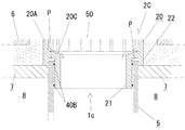
図1に示すように、地中には、ますとしての排水ます4Aが埋設されている。該排水ま
す4Aには、所定勾配で配された排水管4B,4Bが両側から接続されていると共に、地
表に向かって起立状に立上り管5が接続されている。なお、前記排水ます4A、排水管4
B、及び立上り管5は、公知品が好適に採用される。
As shown in FIG. 1, a
Known products are preferably used for B and the
また、前記立上り管5の周囲には、掘削された土が埋め戻されてなる埋め戻し層8と、
該埋め戻し層8上に配されたモルタル下地層7とからなる地盤gが形成されている。また
、さらに該モルタル下地層7上には、目地剤11を介して仕上げ部材としてのインターロ
ッキングブロック6が複数並べて敷設され、該インターロッキングブロック6の上面によ
り、いわゆるグランドレベルGL(地表)が構成されている。なお、該モルタル下地層7
は、その他の材料を用いて下地層としても勿論よい。また、前記仕上げ部材は、特にイン
ターロッキングブロック6に限定されることはなく、石材、素焼きレンガ、タイル、人工
芝等の他の部材が使用されても勿論よい。
Further, a
A ground g composed of a
Of course, other materials may be used as the underlayer. Further, the finishing member is not particularly limited to the
また、前記立上り管5の上端には、本発明に係る蓋枠2Aが配置され、さらに該蓋枠2
Aに化粧蓋本体3(蓋本体)が取り付けられている。
Further, a
A decorative lid body 3 (lid body) is attached to A.
そしてさらに、図1に示す施工完了状態にあっては、化粧蓋本体3の上面と、インター
ロッキングブロック6の上面とが面一となる。これにより、整一な仕上がりの地表面が形
成されている。
Furthermore, in the construction completion state shown in FIG. 1, the upper surface of the
次に、上記化粧蓋本体3について説明する。
化粧蓋本体3は、図2,5に示すように、受け部9Aと、内嵌部9Bと、仕上げ部とし
てのインターロッキングブロック6とで構成されている。さらに詳述すると、図5に示す
ように、前記受け部9Aは、平面視正方形状の皿形状であり、該受け部9Aの下面中央か
ら円筒形の内嵌部9Bが下方へ突出している。また、前記受け部9Aに、前記インターロ
ッキングブロック6と同一素材からなるインターロッキングブロック6が目地剤11を介
して配設されている。なお、前記内嵌部9Bの外周には、円環状のゴムパッキン40Aが
被着されており、当該内嵌部9Bが後述の蓋枠2Aの円形開口24に挿入されると、該内
嵌部9Bが該円形開口24に対して水密状に内嵌される。
ところで、前記受け部9Aを平面視正方形状とすると、矩形状のインターロッキングブ
ロック6で構成される化粧蓋本体3が製造し易いと共に、模様合わせが容易となり、また
施工時の美観も向上する。
Next, the
As shown in FIGS. 2 and 5, the decorative lid
By the way, when the receiving
次に、本発明の要部に係る蓋枠2Aについて説明する。
蓋枠2Aは、図2,3,5に示すように、平面視正方形状の蓋本体受容部20を備えて
いる。この蓋本体受容部20は、水平の底部20Bと該底部20Bの周縁から垂直に起立
した側壁20Aとを備えると共に、前記底部20Bの中央に円形開口24が形成されてい
る。そして、該円形開口24に前記化粧蓋本体3の内嵌部9Bが挿入され、かつ該底部2
0Bと前記該化粧蓋本体3の下面とが面接触するようにして、かかる蓋本体受容部20に
、前記化粧蓋本体3が受容される。すなわち、前記底部20Bの上面が化粧蓋本体3を支
持する支持面となっている。
Next, the
As shown in FIGS. 2, 3, and 5, the lid frame 2 </ b> A includes a lid
The
また、前記蓋本体受容部20の下面中央からは、前記円形開口24と連通した円筒形の
立上り管挿入部21が下方に向けて突出状に差し出されている。さらに、この立上り管挿
入部21の外周には、円環状のゴムパッキン40Bが二つ上下に被着されており、この立
上り管挿入部21が前記立上り管5の上端開口5Bに挿入されると、該立上り管挿入部2
1が立上り管5に水密状に内嵌される。
さらに図6に示すように、蓋本体受容部20の1辺R1と、前記立上り管挿入部21の外径R2とは等しく設定されている。
かかる構成とすることにより、立上り管5の外径に対して最小限の蓋面積が確保されることとなり、地表面において省スペース化が図られ、立上り管5を密集させて設置することが可能となる。なお、本発明は、蓋本体受容部20が平面視矩形状であって、該蓋本体受容部20の少なくとも1辺が、前記立上り管挿入部21の外径に等しい構成を含むものである。したがって、平面視長方形の蓋本体受容部20に対して、立上り管挿入部21の外径が該蓋本体受容部20の短辺に等しい構成も本発明に含まれる。
Further, from the center of the lower surface of the lid main
1 is fitted into the
Furthermore, as shown in FIG. 6, one side R1 of the lid
By adopting such a configuration, a minimum cover area is secured with respect to the outer diameter of the
さらに、前記蓋本体受容部20における前記側壁20Aの下部には、下方へ突出する支
持部22が前記立上り管挿入部21の外周側に該立上り管挿入部21に対して間隔を置い
て形成されている。なお、該支持部22は、蓋本体受容部20の外周において4つの角部のそれぞれにL字状に形成されている。そして、該支持部22と、前記立上り管挿入部21の両端部との間隙が、前記立上り管5の肉厚と略等しい溝幅で下方に向けて開口した立上り管挿入溝Pとなっている。なお、前記支持部22は、蓋本体受容部20の外周から立上り管挿入溝Pを介して配設されることとなり、該支持部22の下端は、施工完了状態にあって、前記モルタル下地層7上面(すなわち地盤g上面)に当接することとなる。
Further, a
また、前記立上り管挿入溝Pは、施工完了状態にあって、下方から進入した立上り管5
の上端部5Aが挿入される。なお、かかる立上り管挿入溝Pの作用効果については、後で
詳しく述べる。
The rising pipe insertion groove P is in a construction completed state, and the rising
5A is inserted. The effect of the riser insertion groove P will be described in detail later.
次に、ます蓋1aの施工手順を説明する。
まず、排水ます4Aを地中に配置すると共に、該排水ます4Aの上に立上り管5を立設
する。ここで、この時点での立上り管5の上端部5C(以下、仮上端部5Cという。)は
、後述するモルタル下地層7の打設等の作業性を良好とすべく、図4に示すように、施工
完了時の高さよりも余分に突き出した高さとしておくのが望ましい。例えばモルタル下地
層7の上面となるラインから立上り管5の仮上端部5Cまでの突出高さをL2としておく
。
Next, the construction procedure of the
First, the
立上り管5を立設した後、該立上り管5の周りを埋め戻して埋め戻し層8を形成し、さ
らに、該埋め戻し層8上にモルタルを打設してモルタル下地層7を形成する。ここで、モ
ルタル下地層7の上面となるラインは、後述するように、施工完了時のインターロッキン
グブロック6の上面高さ(いわゆるGL)を考慮して設定される。なお、上述した排水ま
す4Aの配置、排水ます4Aと立上り管5の接続、埋め戻し、モルタルの打設は公知技術
が好適に採用される。
After the
そして次に、前記立上り管5の余分な突き出し部分を切断して、該立上り管5における
モルタル下地層7上面からの突出高さをL1とする。ここで、この突出高さL1は、後述
するように、0≦L1≦h(h=立上り管挿入溝Pの溝深さ)の範囲内にある高さとすれ
ばよく、特に厳密な高さ精度は要求されない。ここで、勿論、立上り管5の立設時におい
てあらかじめ突出高さL2が、0≦L2≦hの範囲となるように設定されている場合は、
特段、上述のような切断作業は必要でない。なお、前記の高さ「h」は、立上り管挿入溝
Pの溝深さに相当する。
Next, an excessive protruding portion of the
In particular, the cutting operation as described above is not necessary. The height “h” corresponds to the groove depth of the riser insertion groove P.
次に、突出高さL1とされた立上り管5の上端に、蓋枠2Aを配置する。具体的には、
蓋枠2Aの立上り管挿入部21を前記立上り管5の上端開口5Bに挿入する。そして、そ
のまま蓋枠2Aを下方に押し下げていき、当該蓋枠2Aの支持部22の下端をモルタル下
地層7の上面と当接させる。そうすると、蓋枠2Aが立上り管5に固定されて蓋枠2Aが
位置決めされる。ところで、蓋枠2Aを下方に押し下げる過程にあっては、立上り管5の
上端部5Aが、蓋枠2Aの立上り管挿入溝Pに挿入される。そして、蓋枠2Aが固定され
た状態にあっては、立上り管5の上端部5Aが該立上り管挿入溝P内に位置することとな
る。なお、該立上り管挿入溝Pの左右方向の溝幅は、立上り管5の肉厚と略等しくなるよ
うに寸法設計されているため、蓋枠2Aはガタツキなく立上り管5に連結される。
Next, the
The rising
ところで、上述のように、蓋枠2Aの装着前に、立上り管5の突出高さL1を予め0≦
L1≦hとしておくことによって、立上り管5の上端部5Aは、適正に立上り管挿入溝P
内に収まることとなる。逆に、h<L1であると、支持部22の下端がモルタル下地層7
に当接する前に、立上り管5の上端部5Aが立上り管挿入溝Pの溝底に突き当たってしま
って適正な配置が行なえない。また、突出高さL1をモルタル下地層7の上面より低く設
計してしまうと、インカッター等の特殊工具を使用する必要があり、作業効率が悪化する
。
By the way, as described above, the protrusion height L1 of the
By setting L1 ≦ h, the
Will fit within. On the contrary, when h <L1, the lower end of the
The
上記手順により蓋枠2Aが立上り管5上に配置された後、該蓋枠2Aの円形開口24に
化粧蓋本体3の内嵌部9Bを上から挿入し、該化粧蓋本体3を前記蓋本体受容部20に収
容する。このとき、周囲のインターロッキングブロック6の上面と、当該化粧蓋本体3の
上面とは面一となる。
After the
このように、本発明に係る蓋枠2Aを使用すれば、施工時に立上り管5の上端部5Aを
、立上り管挿入溝P内に収まる範囲内で切断すればよく、従来のように立上り管5を正確
かつ精密に切断して高さ設定しておく必要がない。そして、地盤上面(上記実施例にあっ
てはモルタル下地層7の上面)に対して確実に一定高さで蓋枠2Aを設置できる。このた
め、ます蓋1aの現場施工が、極めて簡便なものとなり、施工に高度な熟練を要しない。
As described above, when the
なお、本蓋枠2Aは、施工完了時にインターロッキングブロック6と化粧蓋本体3の上
面とが面一となるように、寸法設計されて成形加工される。なお、本実施例に係る蓋枠2
Aは、塩ビ材料で射出成形されたものであるが、特にこれに限定されることはない。
The
A is injection-molded with a PVC material, but is not particularly limited thereto.
〈変形例1〉
上記構成の変形例が提案される。
図7は、変形例に係るます蓋1bの施工状態を示している。かかるます蓋1bは、垂直
に起立した立上り管5の周囲にモルタル下地層7の上面を所定角度で傾斜(図において右
側に下方傾斜)して形成し、さらにこの傾斜に沿って地表面を同様に傾斜させて、該地表
面と面一に化粧蓋本体3を傾斜して設置したものである。
<Modification 1>
A modification of the above configuration is proposed.
FIG. 7 shows a construction state of the
さらに詳述すると、該ます蓋1bの蓋枠2Bは、前記立上り管挿入溝Pの溝幅が、立上
り管5の上端部5Aの肉厚より十分に幅広とされている。また、該蓋枠2Bの立上り管挿
入部21にはパッキンが被着されていない。
More specifically, in the
かかる構成にあっては、立上り管挿入溝Pと立上り管5の上端部5Aとの間にいわゆる
「遊び」ができ、立上り管挿入溝P内で前記上端部5Aが相対的に斜めに配置される状態
となって垂直な立上り管5に対して該蓋枠2Bを傾けて取り付けることが可能となる。換
言すれば、上記した図1に示す構成は立上り管挿入溝Pの溝深さ方向と立上り管5の管軸
方向(鉛直方向)とが一致していたが、本変形例においては、前記溝深さ方向(図6にお
いて矢印方向)と前記管軸方向(鉛直方向)とが一致していない。これにより、地盤上面
に沿って該蓋枠2Bを傾けて取り付けることが可能となって、さらに化粧蓋本体3の上面
を傾斜した地表面と面一又は平行に取り付けて整一な仕上がりの地表面を形成することが
できる。
In such a configuration, a so-called “play” can be made between the riser tube insertion groove P and the
なお、前記立上り管5と前記蓋枠2Bは、相互に非接触とする構成でもよいが、蓋枠2
Bにおける支持部22を立上り管5の外面にも当接させる、及び/又は、蓋枠2Bにおけ
る立上り管挿入部21の下端を立上り管5の内面に当接させ構成が、蓋枠2Bのガタツキ
が防止されて望ましい。ところで、前記の立上り管挿入溝Pは、立上り管5の肉厚より広
い溝幅であるから、設置作業が容易である。
The
The structure in which the
また、上記構成は垂直な立上り管5に対して斜めに蓋枠2Bを配置する構成であるが、
斜めに立ち上がる立上り管に対して水平に地盤を形成し、該地盤上面に水平に蓋枠を設定
する構成としてもよい。
In addition, the above configuration is a configuration in which the
A ground may be formed horizontally with respect to the rising pipe rising obliquely, and a cover frame may be set horizontally on the upper surface of the ground.
(削除) ( Delete )
(削除) ( Delete )
〈変形例2〉
さらに、別の変形例のます蓋1cが提案される。
図8に示すように、ます蓋1cの蓋枠2Cは、蓋本体受容部20の底部を、中央の円形
開口24に向けて下方傾斜させたテーパー底部20Cとしたものである。そして、本蓋枠
2Cには公知のグレーチング蓋本体(蓋本体)50を取り付ける構成が望ましい。かかる
構成とすることにより、地表面でグレーチング蓋本体50に向かって雨水が流れた際にも
、グレーチング蓋本体50にある通水孔から落下した雨水が蓋枠2Cのテーパー底部20
C上を流れ、適正に立上り管5へ該雨水を案内することが可能となる。
<Modification 2 >
Furthermore, another variant of the
As shown in FIG. 8, the lid frame 2 C of the
It becomes possible to guide the rainwater to the
なお、これまでに述べた当該蓋枠2A〜2Cは、雨水ます用でも浸透ます用でもよく、
蓋本体3,50としては、マンホール蓋、又はグレーチング蓋等が目的に応じて使用され
てもよい。
The lid frames 2A to 2C described so far may be used for rainwater or permeate,
As the
また、上記蓋枠2A〜2Cは、本発明の要旨を逸脱しない限り、適宜設計変更すること
が可能である。
The lid frames 2A to 2C can be appropriately changed in design without departing from the gist of the present invention.
1a〜1c ます蓋
2A〜2C 蓋枠
3 化粧蓋本体(蓋本体)
4A 排水ます(ます)
5 立上り管
5A 立上り管の上端部
5B 立上り管の上端開口
6 インターロッキングブロック(仕上げ部材)
20 蓋本体受容部
21 立上り管挿入部
22 支持部
50 化粧蓋(蓋本体)
g 地盤
P 立上り管挿入溝
1a to 1c
4A drains (mass)
5 Rising
20 Lid main
g Ground P Rise pipe insertion groove
Claims (3)
前記蓋本体を受容する蓋本体受容部と、
該蓋本体受容部の下面から下方に差し出された立上り管挿入部と、
該立上り管挿入部が前記立上り管の上端開口に挿入された状態で該立上り管周辺の地盤上面に当接して前記蓋本体受容部を支持する支持部と
を備え、
前記支持部は、前記蓋本体受容部の外周から下方に向けて、前記立上り管挿入部の外周側に立上り管挿入溝を介して配設されてなり、前記立上り管挿入部が前記立上り管の上端開口に挿入されかつ前記支持部の下端が前記地盤上面に当接した状態で、前記立上り管挿入溝に該立上り管の上端部が挿入されるように設定されている蓋枠と、該蓋枠に取り付けられる蓋本体とからなるます蓋の施工方法であって、
前記蓋枠の前記蓋本体受容部は、平面視矩形の蓋本体が取り付けられる平面視矩形状であり、
該蓋本体受容部に設けられた立上り管挿入部が、円筒形状の立上り管の上端開口に挿入される円筒形状であって、
前記蓋本体受容部の少なくとも1辺は、前記立上り管挿入部の外径に等しく設定されており、
前記立上り管の周囲に地盤を形成した後、該立上り管の該地盤上面からの突出高さL1が、
0≦L1≦h (h=前記立上り管挿入溝の溝深さ)
の範囲内となるように該立上り管の高さを設定し、次に、該立上り管の上端開口に前記蓋枠の前記立上り管挿入部を挿入すると共に前記立上り管挿入溝に該立上り管の上端部を挿入し、さらに前記支持部の下端を該地盤上面に当接させて該蓋枠を該立上り管上に配置することを特徴とするます蓋の施工方法。 In the lid frame that is placed on the riser that rises toward the surface of the earth, buried in the ground, and to which the lid body is attached,
A lid body receiving portion for receiving the lid body;
A riser insertion portion that is extended downward from the lower surface of the lid body receiving portion;
A support portion for supporting the lid body receiving portion in contact with the ground upper surface around the riser tube in a state where the riser tube insertion portion is inserted into the upper end opening of the riser tube,
The support portion is disposed from the outer periphery of the lid main body receiving portion downward to the outer peripheral side of the riser tube insertion portion via a riser tube insertion groove, and the riser tube insertion portion is connected to the riser tube. A lid frame that is inserted into the upper end opening and is set so that the upper end portion of the rising pipe is inserted into the rising pipe insertion groove in a state where the lower end of the support portion is in contact with the upper surface of the ground; A lid construction method comprising a lid body attached to a frame,
The lid body receiving portion of the lid frame has a rectangular shape in plan view to which a lid body having a rectangular shape in plan view is attached,
The riser tube insertion portion provided in the lid body receiving portion has a cylindrical shape inserted into the upper end opening of the cylindrical riser tube,
At least one side of the lid body receiving portion is set equal to the outer diameter of the riser insertion portion,
After forming the ground around the riser, the protruding height L1 of the riser from the top surface of the ground is:
0 ≦ L1 ≦ h (h = groove depth of the riser insertion groove)
The height of the riser is set so as to fall within the range, and then the riser insertion portion of the lid frame is inserted into the upper end opening of the riser and the riser is inserted into the riser insertion groove. A method of constructing a lid, comprising: inserting an upper end portion, and further placing the lid frame on the riser pipe by bringing the lower end of the support portion into contact with the upper surface of the ground.
An upper surface of the ground is formed by inclining with respect to the pipe axis direction of the riser, an upper end of the riser is inserted obliquely into the riser insertion groove, and a lower end of the support portion of the lid frame is inserted into the upper surface of the ground. The method for constructing a lid according to claim 1 or 2, wherein the lid frame is arranged in contact with each other.
Priority Applications (1)
| Application Number | Priority Date | Filing Date | Title |
|---|---|---|---|
| JP2008096041A JP5317514B2 (en) | 2008-04-02 | 2008-04-02 | How to install the lid |
Applications Claiming Priority (1)
| Application Number | Priority Date | Filing Date | Title |
|---|---|---|---|
| JP2008096041A JP5317514B2 (en) | 2008-04-02 | 2008-04-02 | How to install the lid |
Publications (2)
| Publication Number | Publication Date |
|---|---|
| JP2009249844A JP2009249844A (en) | 2009-10-29 |
| JP5317514B2 true JP5317514B2 (en) | 2013-10-16 |
Family
ID=41310800
Family Applications (1)
| Application Number | Title | Priority Date | Filing Date |
|---|---|---|---|
| JP2008096041A Expired - Fee Related JP5317514B2 (en) | 2008-04-02 | 2008-04-02 | How to install the lid |
Country Status (1)
| Country | Link |
|---|---|
| JP (1) | JP5317514B2 (en) |
Family Cites Families (8)
| Publication number | Priority date | Publication date | Assignee | Title |
|---|---|---|---|---|
| JPS6014147U (en) * | 1983-07-08 | 1985-01-30 | 西武機材株式会社 | Frame for box cover |
| JPH0297482U (en) * | 1989-01-20 | 1990-08-02 | ||
| JPH0450448U (en) * | 1990-08-31 | 1992-04-28 | ||
| JP2568844Y2 (en) * | 1993-06-15 | 1998-04-15 | 積水化学工業株式会社 | Cleaning port lid |
| JPH08326146A (en) * | 1995-05-30 | 1996-12-10 | Yutaka Takatsu | Catch basin |
| JPH11323986A (en) * | 1998-05-08 | 1999-11-26 | Gifu Plast Ind Co Ltd | Manhole for sloping place |
| JP3065680U (en) * | 1999-06-07 | 2000-02-08 | 株式会社田矢桂ボイラー | Synthetic double pig |
| JP2002070141A (en) * | 2000-08-25 | 2002-03-08 | Iwakiri Concrete Kogyo:Kk | Soil chamber made of polyvinyl chloride |
-
2008
- 2008-04-02 JP JP2008096041A patent/JP5317514B2/en not_active Expired - Fee Related
Also Published As
| Publication number | Publication date |
|---|---|
| JP2009249844A (en) | 2009-10-29 |
Similar Documents
| Publication | Publication Date | Title |
|---|---|---|
| CN109281299B (en) | Construction method of water conservancy agricultural irrigation seepage-proofing channel | |
| JP2023072625A (en) | Road surface forming auxiliary member and road surface forming method | |
| KR100676681B1 (en) | Supprot apparatus of drainage | |
| CN107460886B (en) | Light steel structure assembly and decoration integrated building foundation and construction method thereof | |
| KR200409783Y1 (en) | Supprot apparatus of drainage | |
| JP5317514B2 (en) | How to install the lid | |
| KR200428388Y1 (en) | Power transmission manhole | |
| KR20090085830A (en) | Structure of water pipe for building | |
| JP4410572B2 (en) | Construction method of revetment for landfill | |
| JP2023072118A (en) | Road surface forming auxiliary member and road surface forming method | |
| KR100487838B1 (en) | Prefabricated retaining wall and it's construction method | |
| JP2007077591A (en) | Artificial ground | |
| JP2006274657A (en) | Construction method of building foundation structure | |
| KR200363330Y1 (en) | Pipe support for being laid under the ground | |
| WO2023281807A1 (en) | Road surface molding auxiliary member | |
| JP5767989B2 (en) | Ground liquefaction countermeasure structure and construction method | |
| KR101239038B1 (en) | Base ground construction method for concrete waterway pipe | |
| JP3171169U (en) | Headstone foundation | |
| JP2019044562A (en) | Construction method of side ditch, and underground embedded cylinder member | |
| JP2978886B1 (en) | Masu structure in gutter and construction method of the masu structure | |
| KR20050082811A (en) | A construction method of a wall for supporting a soil | |
| JP2016041884A (en) | Border block structure between adjacent residential areas and construction method for block installation | |
| KR101624730B1 (en) | Pedestal structure for water pipeline used in waterworks and drainage, road, river bank and drainage works | |
| KR200357962Y1 (en) | Prefabricated concrete retaining wall | |
| JP2016017378A (en) | Base-isolated building and construction method therefor |
Legal Events
| Date | Code | Title | Description |
|---|---|---|---|
| A621 | Written request for application examination |
Free format text: JAPANESE INTERMEDIATE CODE: A621 Effective date: 20101119 |
|
| A977 | Report on retrieval |
Free format text: JAPANESE INTERMEDIATE CODE: A971007 Effective date: 20120307 |
|
| A131 | Notification of reasons for refusal |
Free format text: JAPANESE INTERMEDIATE CODE: A131 Effective date: 20120313 |
|
| A521 | Written amendment |
Free format text: JAPANESE INTERMEDIATE CODE: A523 Effective date: 20120511 |
|
| A131 | Notification of reasons for refusal |
Free format text: JAPANESE INTERMEDIATE CODE: A131 Effective date: 20130307 |
|
| A521 | Written amendment |
Free format text: JAPANESE INTERMEDIATE CODE: A523 Effective date: 20130418 |
|
| TRDD | Decision of grant or rejection written | ||
| A01 | Written decision to grant a patent or to grant a registration (utility model) |
Free format text: JAPANESE INTERMEDIATE CODE: A01 Effective date: 20130618 |
|
| A61 | First payment of annual fees (during grant procedure) |
Free format text: JAPANESE INTERMEDIATE CODE: A61 Effective date: 20130709 |
|
| R150 | Certificate of patent or registration of utility model |
Free format text: JAPANESE INTERMEDIATE CODE: R150 |
|
| LAPS | Cancellation because of no payment of annual fees |