JP5316006B2 - Foamed structure and method for producing foamed structure - Google Patents
Foamed structure and method for producing foamed structure Download PDFInfo
- Publication number
- JP5316006B2 JP5316006B2 JP2009005762A JP2009005762A JP5316006B2 JP 5316006 B2 JP5316006 B2 JP 5316006B2 JP 2009005762 A JP2009005762 A JP 2009005762A JP 2009005762 A JP2009005762 A JP 2009005762A JP 5316006 B2 JP5316006 B2 JP 5316006B2
- Authority
- JP
- Japan
- Prior art keywords
- foam
- foam material
- foamed
- rigidity
- filler
- Prior art date
- Legal status (The legal status is an assumption and is not a legal conclusion. Google has not performed a legal analysis and makes no representation as to the accuracy of the status listed.)
- Expired - Fee Related
Links
Images


Description
本発明は、発泡構造体および発泡構造体の製造方法に関する。 The present invention relates to a foam structure and a method for producing the foam structure.
従来、車両のインストルメントパネル等の発泡成形パネルに被取付部品を取り付ける構造として、発泡成形パネルに被取付部品を突き当てて被取付部品を位置決めし、この状態で被取付部品を発泡成形パネルに固定するものが知られている(例えば、特許文献1参照)。この発泡成形パネルは、内部に発泡構造体としての発泡層を有している。 Conventionally, as a structure for mounting a mounted part on a foam molded panel such as an instrument panel of a vehicle, the mounted part is abutted against the foam molded panel to position the mounted part, and in this state, the mounted part is attached to the foam molded panel. What is fixed is known (for example, refer patent document 1). This foam-molded panel has a foam layer as a foam structure inside.
しかしながら、上記の従来構造では、発泡成形パネルに被取付部品を突き当てると、発泡層が変形するため、被取付部品の位置決め精度が低いという問題がある。 However, the conventional structure has a problem in that the positioning accuracy of the mounted component is low because the foamed layer is deformed when the mounted component is abutted against the foam molded panel.
そこで、本発明は、発泡構造体の変形を抑制することを目的とする。 Then, an object of this invention is to suppress a deformation | transformation of a foam structure.
本発明の発泡構造体は、基材と表皮材との間に第1の発泡材と第2の発泡材とが設けられた構造であって、前記第2の発泡材は、その一部が前記第1の発泡材に充填されて前記第1の発泡材の内部に位置しているとともに他の部分が前記第1の発泡材の外部に位置しており、前記第2の発泡材のうち前記第1の発泡材内に位置する部分と前記第1の発泡材とからなる複合体の剛性が、前記第2の発泡材のうち前記第1の発泡材外に位置する部分の剛性よりも高いことを特徴とする。 The foamed structure of the present invention is a structure in which a first foamed material and a second foamed material are provided between a base material and a skin material, and the second foamed material has a part thereof. The first foam material is filled and located inside the first foam material, and the other part is located outside the first foam material, of the second foam material The rigidity of the composite composed of the portion located in the first foam material and the first foam material is greater than the stiffness of the portion of the second foam material located outside the first foam material. It is characterized by being expensive.
本発明の発泡構造体の製造方法は、基材における第1の発泡材が固定された面に間隔をあけて対向配置した表皮材と前記基材との間と、前記第1の発泡材とに、充填材を充填する工程と、前記充填材を発泡させて固体状の第2の発泡材を形成して、前記第2の発泡材のうち前記第1の発泡材内に位置する部分と前記第1の発泡材とからなる複合体を形成する工程と、を含み、前記複合体を形成する工程は、前記第2の発泡材のうち前記第1の発泡材外に位置する部分の剛性よりも前記複合体の剛性を高くすることを特徴とする。 The method for producing a foam structure according to the present invention includes a surface material between the base material and the base material, which are arranged to face each other with a space on the surface of the base material on which the first foam material is fixed, and the first foam material. A step of filling the filler, forming a solid second foam material by foaming the filler, and a portion of the second foam material located within the first foam material; Forming a composite made of the first foam material, and the step of forming the composite comprises a rigidity of a portion of the second foam material located outside the first foam material. Further, the rigidity of the composite is increased.
本発明によれば、第2の発泡材のうち第1の発泡材内に位置する部分と第1の発泡材とからなる複合体の剛性が、第2の発泡材のうち第1の発泡材外に位置する部分の剛性よりも高いことにより、発泡構造体の変形を抑制することができる。 According to the present invention, the rigidity of the composite composed of the first foamed material and the portion of the second foamed material located in the first foamed material is the first foamed material of the second foamed material. By being higher than the rigidity of the part located outside, deformation of the foam structure can be suppressed.
以下、本発明の一実施形態について図面を参照しながら説明する。 Hereinafter, an embodiment of the present invention will be described with reference to the drawings.
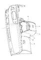
図1および図2に示すように、本実施形態の自動車のインストルメントパネル1には、トレイロア2とボックスカバー3とが取り付けられ、ボックスカバー3には、リッド4が取り付けられる。
As shown in FIGS. 1 and 2, a tray lower 2 and a
トレイロア2は、左側壁5と、右側壁6と、これらの左右側壁5,6を連結する連結部7とを有している。そして、左側壁5の表面9bには、ボックスカバー3の側部に形成された突当部3aが突き当てられ、これにより、ボックスカバー3の位置決めがなされるようになっている。
The
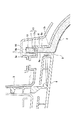
トレイロア2の左側壁5は、図3および図4に示すように、基材8と、この基材8に対向配置された対向部材としての表皮材9と、これら基材8および表皮材9の間に介在した発泡構造体10と、を備えて構成されている。
As shown in FIGS. 3 and 4, the
発泡構造体10は、第1の発泡材11と第2の発泡材12とを備えて層状に形成されている。第1の発泡材11は、気泡同士が繋がって形成された連続気泡構造を有し、かかる連続気泡構造によって、第1の発泡材11の内部には流路が形成されている。発泡構造体10は、例えば、ポリウレタンフォームによって形成されている。このポリウレタンフォームとしては、密度が0.0180〜0.0220g/cm3、硬さが9.5〜13.5kgf、伸び率が130%以上であることが好ましい。
The
第2の発泡材12は、その一部12aが第1の発泡材11の内部(流路)に充填されて第1の発泡材11の内部に位置しているとともに他の部分12bが第1の発泡材11の外部に位置している。第2の発泡材12の発泡構造は、連続気泡構造であっても良いし、気泡同士が独立している独立気泡構造であっても良い。第2の発泡材12は、ポリウレタンフォームによって形成されている。
The second
第2の発泡材12のうち第1の発泡材11内に位置する部分12aの空隙率は、第2の発泡材12のうち第1の発泡材11外に位置する部分12bの空隙率よりも低くなっている。そして、第2の発泡材12のうち第1の発泡材11内に位置する部分12aと第1の発泡材11とによって複合体13が構成されている。この複合体13の剛性は、第2の発泡材12のうち第1の発泡材11外に位置する部分12bの剛性よりも高くなっている。
The porosity of the portion 12a located in the
次に、発泡構造体10の製造方法について説明する。まず、第1の工程として、固体状の第1の発泡材11を、基材8の裏面8aに例えば接着によって固定する。このとき、第1の発泡材11の流路は空であるので、流動体が第1の発泡材11の内部(流路)を通過可能となっている。ここで、基材8は、例えば樹脂の射出成形によって成形してよい。
Next, a method for manufacturing the
次に、第2の工程として、基材8における第1の発泡材11が固定された面である裏面8aに間隔をあけて表皮材9を対向配置し、この表皮材9の裏面9aと基材8の裏面8aとの間と、第1の発泡材11とに、充填材を充填する。これにより第1の発泡材11に充填材が含浸する。この充填材は、発泡性および流動性を有していて未発泡状態のものであり、本実施形態では、ポリウレタンと発泡剤とを含んだ充填材が適用されている。
Next, as a second step, the
次に、第3の工程として、充填材を加熱して充填材を発泡させて固体状の第2の発泡材12を形成し、これにより、第2の発泡材12のうち第1の発泡材11内に位置する部分12aと第1の発泡材11とからなる複合体13を形成する。この第3の工程においては、充填材のうち第1の発泡材11中の充填材の気泡の成長が第1の発泡材11によって抑制され、これにより、第2の発泡材12のうち第1の発泡材11内に位置する部分12aの空隙率が第2の発泡材12のうち第1の発泡材11外に位置する部分12bの空隙率よりも低くなり、第2の発泡材12のうち第1の発泡材11外に位置する部分12bの剛性よりも複合体13の剛性が高くなる。
Next, as a third step, the filler is heated to foam the filler to form a solid
以上説明したように、本実施形態の発泡構造体10は、第1の発泡材11と第2の発泡材12とを備えており、第2の発泡材12のうち第1の発泡材11内に位置する部分12aと第1の発泡材11とからなる複合体13の剛性が、第2の発泡材12のうち第1の発泡材11外に位置する部分12bの剛性よりも高い。したがって、第1の発泡材が設けられず第2の発泡材だけで発泡構造体が構成された場合に比べ、複合体13の分だけ発泡構造体10の剛性が向上しているので、発泡構造体10の変形を抑制することができる。かかる構造の発泡構造体10では、複合体13を他部材の位置決め用部材として用いることができる。具体的には、複合体13に対応する部分のトレイロア2の左側壁5の表面9bに被取付部品としてのボックスカバー3を突き当てることで、複合体13によってボックスカバー3を良好に位置決めすることができる。よって、トレイロア2とボックスカバー3との組み付け寸法精度を向上することができる。また、このように、発泡構造体10の変形を抑制することができるので、トレイロア2の外観品質の向上および取付精度の向上を図ることができ、ひいては、トレイロア2と他部品との干渉を抑制して、それらの干渉による異音の発生を抑制することができる。
As described above, the
また、本実施形態では、第1の発泡材11および第2の発泡材12は、ポリウレタンフォームであることにより、比較的容易に発泡構造体10を製造することができる。
In the present embodiment, the
また、本実施形態の発泡構造体10の製造方法では、第1の発泡材11の内部を流動体が通過可能であるので、基材8と表皮材9との間における第1の発泡材11の奥側にも第1の発泡材11を通過した充填材が行き渡るので、基材8と表皮材9との間に隙間無く第2の発泡材12を形成することができる。
Further, in the method for manufacturing the
なお、本発明は、本実施形態に限ることなく本発明の要旨を逸脱しない範囲で他の実施形態を各種採用することができる。 The present invention is not limited to this embodiment, and various other embodiments can be adopted without departing from the gist of the present invention.
8 基材
8a 基材の裏面(面)
9 表皮材(対向部材)
10 発泡構造体
11 第1の発泡材
12 第2の発泡材
12a 第2の発泡材の一部
12b 第2の発泡材の他の部分
13 複合体
8 Base material 8a Back surface (surface) of base material
9 Skin material (opposing member)
DESCRIPTION OF
Claims (3)
前記第2の発泡材は、その一部が前記第1の発泡材に充填されて前記第1の発泡材の内部に位置しているとともに他の部分が前記第1の発泡材の外部に位置しており、
前記第2の発泡材のうち前記第1の発泡材内に位置する部分の空隙率が、前記第2の発泡材のうち前記第1の発泡材外に位置する部分の空隙率よりも低くなっており、
前記第2の発泡材のうち前記第1の発泡材内に位置する部分と前記第1の発泡材とからなる複合体の剛性が、前記第2の発泡材のうち前記第1の発泡材外に位置する部分の剛性よりも高いことを特徴とする発泡構造体。 A foam structure in which a first foam material and a second foam material are provided between a base material and a skin material ,
A part of the second foam material is filled in the first foam material and located inside the first foam material, and the other part is located outside the first foam material. And
The porosity of the portion of the second foam material located in the first foam material is lower than the porosity of the portion of the second foam material located outside the first foam material. And
Of the second foamed material, the rigidity of the composite composed of the first foamed material and the portion located in the first foamed material of the second foamed material is outside of the first foamed material. A foam structure characterized by having a rigidity higher than that of a portion located in the area.
流動体が内部を通過可能な固体状の第1の発泡材を、基材に固定する第1の工程と、
前記基材における前記第1の発泡材が固定された面に間隔をあけて対向配置した表皮材と前記基材との間と、前記第1の発泡材とに、発泡性および流動性を有していて未発泡状態の充填材を充填する第2の工程と、
前記充填材を発泡させて固体状の第2の発泡材を形成して、前記第2の発泡材のうち前記第1の発泡材内に位置する部分と前記第1の発泡材とからなる複合体を形成する第3の工程と、
を含み、
前記第3の工程は、前記充填材のうち前記第1の発泡材中の前記充填材の気泡の成長を前記第1の発泡材によって抑制して、前記第2の発泡材のうち前記第1の発泡材内に位置する部分の空隙率を前記第2の発泡材のうち前記第1の発泡材外に位置する部分の空隙率よりも低くし、前記第2の発泡材のうち前記第1の発泡材外に位置する部分の剛性よりも前記複合体の剛性を高くすることを特徴とする発泡構造体の製造方法。 A method for producing a foam structure in which a first foam material and a second foam material are provided between a base material and a skin material ,
A first step of fixing a solid first foaming material through which the fluid can pass through to the substrate;
The first foam material has foamability and fluidity between the skin material and the base material, which are opposed to each other with a space on the surface of the base material on which the first foam material is fixed. And a second step of filling the unfoamed filler,
The composite is formed by foaming the filler to form a solid second foam material, and the portion of the second foam material located in the first foam material and the first foam material. A third step of forming a body;
Including
The third step suppresses the growth of bubbles in the filler in the first foam material among the filler by the first foam material, and the first step in the second foam material. The porosity of the portion located in the foam material is lower than the porosity of the portion located outside the first foam material in the second foam material, and the first foam material in the second foam material. A method for producing a foam structure, wherein the rigidity of the composite is higher than the rigidity of a portion located outside the foam material.
Priority Applications (1)
| Application Number | Priority Date | Filing Date | Title |
|---|---|---|---|
| JP2009005762A JP5316006B2 (en) | 2009-01-14 | 2009-01-14 | Foamed structure and method for producing foamed structure |
Applications Claiming Priority (1)
| Application Number | Priority Date | Filing Date | Title |
|---|---|---|---|
| JP2009005762A JP5316006B2 (en) | 2009-01-14 | 2009-01-14 | Foamed structure and method for producing foamed structure |
Publications (2)
| Publication Number | Publication Date |
|---|---|
| JP2010162735A JP2010162735A (en) | 2010-07-29 |
| JP5316006B2 true JP5316006B2 (en) | 2013-10-16 |
Family
ID=42579327
Family Applications (1)
| Application Number | Title | Priority Date | Filing Date |
|---|---|---|---|
| JP2009005762A Expired - Fee Related JP5316006B2 (en) | 2009-01-14 | 2009-01-14 | Foamed structure and method for producing foamed structure |
Country Status (1)
| Country | Link |
|---|---|
| JP (1) | JP5316006B2 (en) |
Family Cites Families (6)
| Publication number | Priority date | Publication date | Assignee | Title |
|---|---|---|---|---|
| JPS577542Y2 (en) * | 1974-04-24 | 1982-02-13 | ||
| JPS55206A (en) * | 1978-04-10 | 1980-01-05 | Achilles Corp | Manufacture of cushion |
| JPS58185235A (en) * | 1982-04-23 | 1983-10-28 | Toyo Rubber Chem Ind Co Ltd | Manufacture of cushion and its mold |
| JPS63178009A (en) * | 1987-01-19 | 1988-07-22 | Kasai Kogyo Co Ltd | Interior automobile trim part |
| JP2557249B2 (en) * | 1988-03-19 | 1996-11-27 | 株式会社イノアックコーポレーション | Method for manufacturing different hardness cushion body |
| JP4922621B2 (en) * | 2006-02-16 | 2012-04-25 | ダイキョーニシカワ株式会社 | Urethane integrated foam molding |
-
2009
- 2009-01-14 JP JP2009005762A patent/JP5316006B2/en not_active Expired - Fee Related
Also Published As
| Publication number | Publication date |
|---|---|
| JP2010162735A (en) | 2010-07-29 |
Similar Documents
| Publication | Publication Date | Title |
|---|---|---|
| US10149546B2 (en) | Cushion pad of vehicle seat and manufacturing method thereof | |
| JP6866740B2 (en) | Manufacturing method of seat cushion material and foam mold for manufacturing | |
| WO2014054299A1 (en) | Back pad for seat and manufacturing method therefor | |
| JP5316006B2 (en) | Foamed structure and method for producing foamed structure | |
| JP2007007941A (en) | Resin molding | |
| US6966592B2 (en) | Resin-made floor panel structure | |
| JP5808942B2 (en) | Method for manufacturing shock absorbing pad and shock absorbing pad | |
| JP5090124B2 (en) | Seat pad, manufacturing method thereof, and manufacturing method of sheet component | |
| JP5655558B2 (en) | Hollow structure provided with foam reinforcing member and method for manufacturing the same | |
| KR20190001646A (en) | Manufacturing method of slim foam pad for vehicle seat and slim foam pad for vehicle seat manufactured by method thereof | |
| JP5707933B2 (en) | Method for producing hollow structure provided with foam reinforcing member | |
| JP5819699B2 (en) | Ceiling molding material for vehicle and method for manufacturing the same | |
| JP5655559B2 (en) | Hollow structure provided with foam reinforcing member and method for manufacturing the same | |
| JP5178428B2 (en) | Soundproof cover and manufacturing method thereof | |
| JP4697546B2 (en) | Interior material for vehicle and manufacturing method thereof | |
| JP5593183B2 (en) | Vehicle noise reduction device | |
| JP2019094807A (en) | Cover member | |
| JP2019151213A (en) | Instrument panel structure | |
| JP4585437B2 (en) | Manufacturing method of foam with integrated skin | |
| JP2005305917A (en) | Expansion molded part and its manufacturing method | |
| JP5377931B2 (en) | Plastic molded product | |
| JP2022115343A (en) | Cushion pad and manufacturing method thereof | |
| JP5128163B2 (en) | Vehicle seat cushion structure | |
| JP2019147323A (en) | Method for manufacturing foamed resin molded product and foamed resin molded product | |
| JP4827075B2 (en) | Plastic hollow double wall structure |
Legal Events
| Date | Code | Title | Description |
|---|---|---|---|
| A621 | Written request for application examination |
Free format text: JAPANESE INTERMEDIATE CODE: A621 Effective date: 20111128 |
|
| A977 | Report on retrieval |
Free format text: JAPANESE INTERMEDIATE CODE: A971007 Effective date: 20130410 |
|
| A131 | Notification of reasons for refusal |
Free format text: JAPANESE INTERMEDIATE CODE: A131 Effective date: 20130416 |
|
| A521 | Written amendment |
Free format text: JAPANESE INTERMEDIATE CODE: A523 Effective date: 20130517 |
|
| TRDD | Decision of grant or rejection written | ||
| A01 | Written decision to grant a patent or to grant a registration (utility model) |
Free format text: JAPANESE INTERMEDIATE CODE: A01 Effective date: 20130611 |
|
| A61 | First payment of annual fees (during grant procedure) |
Free format text: JAPANESE INTERMEDIATE CODE: A61 Effective date: 20130624 |
|
| R150 | Certificate of patent or registration of utility model |
Ref document number: 5316006 Country of ref document: JP Free format text: JAPANESE INTERMEDIATE CODE: R150 Free format text: JAPANESE INTERMEDIATE CODE: R150 |
|
| LAPS | Cancellation because of no payment of annual fees |