JP5312653B2 - Image forming apparatus - Google Patents
Image forming apparatus Download PDFInfo
- Publication number
- JP5312653B2 JP5312653B2 JP2012179036A JP2012179036A JP5312653B2 JP 5312653 B2 JP5312653 B2 JP 5312653B2 JP 2012179036 A JP2012179036 A JP 2012179036A JP 2012179036 A JP2012179036 A JP 2012179036A JP 5312653 B2 JP5312653 B2 JP 5312653B2
- Authority
- JP
- Japan
- Prior art keywords
- transfer
- elastic member
- image forming
- sheet member
- image
- Prior art date
- Legal status (The legal status is an assumption and is not a legal conclusion. Google has not performed a legal analysis and makes no representation as to the accuracy of the status listed.)
- Expired - Fee Related
Links
Images


Description
本発明は、電子写真方式或いは静電気録方式を利用して像担持体上に形成したトナー像をベルト体上又はベルト体に担持された転写材上に転写する工程を有するレーザービームプリンタ、複写機、ファクシミリ装置などの画像形成装置に関するものである。 The present invention relates to a laser beam printer and a copying machine having a step of transferring a toner image formed on an image carrier using an electrophotographic system or an electrostatic recording system onto a belt body or onto a transfer material carried on the belt body. The present invention relates to an image forming apparatus such as a facsimile apparatus.
従来、例えば電子写真方式を用いる画像形成装置では、像担持体としての電子写真感光体(感光体)上に現像剤像であるトナー像を形成する。そして、トナーの正規の帯電極性とは逆極性の電界を転写手段に与え、転写ベルトに担持されている転写材又は中間転写ベルトの表面に、感光体に担持されているトナー像を静電的に転移させる転写工程が行われる。 Conventionally, for example, in an image forming apparatus using an electrophotographic system, a toner image which is a developer image is formed on an electrophotographic photosensitive member (photosensitive member) as an image carrier. Then, an electric field having a polarity opposite to the normal charging polarity of the toner is applied to the transfer means, and the toner image carried on the photosensitive member is electrostatically applied to the surface of the transfer material or intermediate transfer belt carried on the transfer belt. A transfer step of transferring to is performed.
そのため、転写ベルトや中間転写ベルトなどの移動可能なベルト体を備えた画像形成装置では、転写手段に対して転写工程に必要な電圧を印加する電圧印加手段が設けられる。この一例として、ベルト体を挟んで感光体の対向位置(ベルト体の裏面側)に、電圧印加手段としての高圧電源に接続された転写ローラなどの接触転写部材を、転写手段として配置した構成がある。 For this reason, in an image forming apparatus including a movable belt body such as a transfer belt or an intermediate transfer belt, a voltage applying unit that applies a voltage necessary for the transfer process to the transfer unit is provided. As an example of this, there is a configuration in which a contact transfer member such as a transfer roller connected to a high voltage power source as a voltage applying unit is disposed as a transfer unit at a position facing the photoconductor (on the back side of the belt unit) across the belt unit. is there.
ところが、転写ローラを用いた画像形成装置では、ベルト体と転写ローラとの接触領域(所謂、転写ニップ)が狭いため、ベルト体と感光体との剥離部で剥離放電が発生し、画像不良を引き起こす場合がある。 However, in an image forming apparatus using a transfer roller, a contact area (so-called transfer nip) between the belt body and the transfer roller is narrow, so that a peeling discharge occurs at the peeling portion between the belt body and the photoconductor, resulting in an image defect. May cause.
そこで、転写ニップ幅を十分に確保する転写手段として、フィルムを用いた構成が提案されている。より具体的には、フィルムが、フィルムの支持体と感光体との間で変位可能であり、電圧の供給、非供給による静電吸着力の有無によってベルト体と接離するものがある(特許文献1)。 Therefore, a structure using a film has been proposed as a transfer means for ensuring a sufficient transfer nip width. More specifically, the film is displaceable between the film support and the photoreceptor, and there is a film that contacts and separates from the belt body depending on the presence or absence of electrostatic attraction force by supplying or not supplying voltage (patent) Reference 1).
しかしながら、従来のフィルムを転写手段として用いた画像形成装置では、フィルムのバックアップ部材がないため、フィルムの表面状態、抵抗ムラによって転写不良が生じる場合がある。 However, in a conventional image forming apparatus using a film as a transfer means, since there is no film backup member, a transfer failure may occur due to the film surface state and resistance unevenness.
具体的には、フィルムの静電吸着力のみによりベルト体との接離を行ったとき、フィルムとベルト体との長手方向の接触の均一性が保てず、転写ニップが不安定になる場合がある。フィルムとベルト体との転写ニップの狭い部分若しくは転写ニップが取れない部分においては、十分な転写電流が確保できず、フィルムとベルト体との転写ニップの広い部分に転写電流が多く流れることになる。そのため、フィルムとベルト体との転写ニップの狭い部分若しくは転写ニップが取れない部分においては、転写電流不足が発生して、縦スジ状の転写不良を引き起こす場合がある。 Specifically, when the contact with and separation from the belt body is performed only by the electrostatic attraction force of the film, the uniformity of the longitudinal contact between the film and the belt body cannot be maintained, and the transfer nip becomes unstable. There is. In a portion where the transfer nip between the film and the belt body is narrow or where the transfer nip cannot be taken, a sufficient transfer current cannot be secured, and a large amount of transfer current flows in a wide portion of the transfer nip between the film and the belt body. . Therefore, in a portion where the transfer nip between the film and the belt body is narrow or a portion where the transfer nip cannot be taken, a transfer current shortage occurs, which may cause a vertical stripe-like transfer failure.
又、フィルムの静電吸着を積極的に用いる構成であるため、フィルムとベルト体との摩擦力が大きくなり、ベルト体の駆動トルクアップにより駆動モータなどへの負荷が大きくなることがある。 In addition, since the electrostatic adsorption of the film is positively used, the frictional force between the film and the belt body increases, and the load on the drive motor or the like may increase due to an increase in the driving torque of the belt body.
具体的には、実際にベルト体とフィルムとの間に働く摩擦力は、ベルト体とフィルムとの摩擦係数により決まる力と、フィルムとベルト体とのインピーダンスにより決まる静電吸着力となっている。そのため、転写電圧の供給、非供給によりフィルムの接離を行う場合、フィルムの静電吸着力が大きくなり、ベルト体の駆動トルクの上昇を引き起こすことがある。 Specifically, the frictional force actually acting between the belt body and the film is a force determined by the friction coefficient between the belt body and the film and an electrostatic adsorption force determined by the impedance between the film and the belt body. . For this reason, when the film is brought into and out of contact with the supply or non-supply of the transfer voltage, the electrostatic attraction force of the film is increased, which may increase the driving torque of the belt body.
尚、ベルト体が中間転写ベルト、転写ベルトのいずれの場合でも上述のような課題が同様にある。ベルト体が中間転写ベルトである場合には中間転写ベルト上へのトナー像の転写工程に関して、又ベルト体が転写ベルトである場合には転写ベルトに担持された紙などの転写材へのトナー像の転写工程に関して同様に上述のような現象が発生することがある。 Note that the above-described problem is similarly caused when the belt body is an intermediate transfer belt or a transfer belt. When the belt body is an intermediate transfer belt, the toner image is transferred onto the intermediate transfer belt. When the belt body is a transfer belt, the toner image onto a transfer material such as paper carried on the transfer belt. The same phenomenon as described above may occur in the transfer process.
従って、本発明の目的は、簡易な構成により、ベルト体と転写部材との均一な接触を維持して、良好な転写性を確保し、耐久を通じて安定した画質を得ることのできる画像形成装置を提供することである。 Accordingly, an object of the present invention is to provide an image forming apparatus capable of maintaining a uniform contact between a belt body and a transfer member with a simple configuration, ensuring good transferability, and obtaining a stable image quality through durability. Is to provide.
上記目的は本発明に係る画像形成装置にて達成される。要約すれば、本発明は、トナー像を担持する像担持体と、前記像担持体と接触して移動可能なベルト体と、前記ベルト体を挟んで前記像担持体と対向する位置に設けられた転写手段と、前記転写手段に電圧を印加する電圧印加手段と、を有し、前記転写手段は、弾性部材と、前記ベルト体と前記弾性部材に挟持され前記ベルト体に面で接触するシート部材と、を備え、前記電圧印加手段により前記シート部材に電圧が前記弾性部材を介さずに印加されることで、前記像担持体上のトナー像が前記ベルト体又は前記ベルト体に担持された転写材に転写される画像形成装置において、前記弾性部材は、略直方体形状で電気的に絶縁性であり、一つの面が前記シート部材に面接触するものであり、前記シート部材は前記弾性部材の面によって前記ベルト体に向って押圧されることを特徴とする画像形成装置である。 The above object is achieved by the image forming apparatus according to the present invention. In summary, the present invention is provided at an image carrier that carries a toner image, a belt member that can move in contact with the image carrier, and a position that faces the image carrier across the belt member. A transfer means; and a voltage application means for applying a voltage to the transfer means. The transfer means is an elastic member, and a sheet that is sandwiched between the belt body and the elastic member and contacts the belt body by a surface. And a toner image on the image carrier is carried on the belt body or the belt body by applying a voltage to the sheet member without the elastic member by the voltage applying means. In the image forming apparatus to be transferred to the transfer material, the elastic member has a substantially rectangular parallelepiped shape and is electrically insulative , and one surface is in surface contact with the sheet member, and the sheet member is the elastic member. Depending on the surface An image forming apparatus characterized by being pressed toward the bets body.
本発明によれば、簡易な構成により、ベルト体と転写部材との均一な接触を維持して、良好な転写性を確保し、耐久を通じて安定した画質を得ることができる。 According to the present invention, with a simple configuration, it is possible to maintain uniform contact between the belt body and the transfer member, ensure good transferability, and obtain stable image quality through durability.
以下、本発明に係る画像形成装置を図面に則して更に詳しく説明する。 The image forming apparatus according to the present invention will be described below in more detail with reference to the drawings.
実施例1
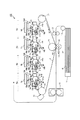
図1は、本発明に係る画像形成装置の一実施例の概略断面構成を示す。本実施例の画像形成装置100は、電子写真方式を用いたレーザービームプリンタである。又、本実施例の画像形成装置100は、イエロー、マゼンタ、シアン、ブラックの各色成分に分解された画像情報に従って形成した各色のトナー像を、中間転写体上に1次転写して一旦重ねた後に転写材に2次転写する、中間転写方式を採用している。先ず、本実施例の画像形成装置の全体構成及び動作を説明する。
Example 1
FIG. 1 shows a schematic sectional configuration of an embodiment of an image forming apparatus according to the present invention. The
画像形成装置100は、複数の画像形成部としてそれぞれイエロー、マゼンタ、シアン、ブラックの各色のトナー像を形成するための4個の画像形成部(ステーション)、即ち、第1、第2、第3、第4の画像形成部Sa、Sb、Sc、Sdを有する。本実施例では、各画像形成部Sa〜Sdの構成及び動作は、それぞれが形成するトナー像の色を除いて実質的に共通である部分が多い。従って、以下の説明において、特に区別を要しない場合は、いずれかの色用に設けられた要素であることを示すために符号に与えた添え字a、b、c、dは省略して総括的に説明する。
The
画像形成部Sは、像担持体としてのドラム型の感光体、即ち、感光ドラム1を有する。感光ドラム1は、駆動手段(図示せず)によって図示矢印R1方向(反時計回り)に回転駆動される。本実施例では、感光ドラム1はOPC(有機光導電体)感光層を有する。画像形成部Sは、感光ドラム1の周囲に、感光ドラム1を帯電させる帯電手段としての帯電ローラ2、露光手段としての露光装置3、現像手段としての現像装置4を有する。又、画像形成部Sは、感光ドラム1の周囲に、1次転写手段としての1次転写部材(転写部材)5、クリーニング手段としてのクリーニング装置6を有する。 The image forming unit S includes a drum-type photosensitive member as an image carrier, that is, a photosensitive drum 1. The photosensitive drum 1 is rotationally driven in a direction indicated by an arrow R1 (counterclockwise) by a driving unit (not shown). In this embodiment, the photosensitive drum 1 has an OPC (organic photoconductor) photosensitive layer. The image forming unit S includes, around the photosensitive drum 1, a charging roller 2 as a charging unit that charges the photosensitive drum 1, an exposure device 3 as an exposure unit, and a developing device 4 as a developing unit. Further, the image forming unit S includes a primary transfer member (transfer member) 5 as a primary transfer unit and a cleaning device 6 as a cleaning unit around the photosensitive drum 1.
クリーニング装置6は、感光ドラム1上のトナーを掻き取ってクリーニングするファーブラシ、ブレードなどのクリーニング部材と、クリーニング部材によって感光ドラム1上から除去されたトナーなどを回収する回収トナー容器とを有する。 The cleaning device 6 includes a cleaning member such as a fur brush and a blade that scrapes and cleans the toner on the photosensitive drum 1, and a collected toner container that collects the toner removed from the photosensitive drum 1 by the cleaning member.
現像装置4は、本実施例では、反転現像方式により静電像を現像する。即ち、現像装置4は、感光ドラム1の帯電極性と同極性である正規の極性(本実施例では負極性)に帯電したトナーを、帯電処理された後に露光によって電荷が減衰した感光ドラム1上の部分(明部)に付着させて、感光ドラム1上にトナー像を形成する。又、現像装置4は、本実施例では、現像剤として非磁性1成分現像剤、即ち、トナーを用いる。そして、現像装置4は、現像剤担持体としての現像ローラ41上に、現像剤規制部材としての現像剤塗布ブレード42を用いてトナーを担持して感光ドラム1との対向部(現像部)まで搬送するようになっている。
In this embodiment, the developing device 4 develops the electrostatic image by a reversal development method. In other words, the developing device 4 applies the toner charged to a normal polarity (negative polarity in this embodiment) that is the same as the charging polarity of the photosensitive drum 1 on the photosensitive drum 1 whose charge has been attenuated by exposure after being charged. A toner image is formed on the photosensitive drum 1 by being attached to the portion (bright portion). In the present embodiment, the developing device 4 uses a non-magnetic one-component developer, that is, toner, as the developer. The developing device 4 carries toner on a developing roller 41 as a developer carrying member using a
又、露光装置3は、レーザー光を多面鏡によって走査させるレーザースキャナユニット、又はLEDアレイなどで構成することができるが、本実施例ではレーザースキャナユニットを用いた。露光装置3は、画像信号に基づいて変調された走査ビーム18を感光ドラム1上に照射する。 The exposure apparatus 3 can be constituted by a laser scanner unit that scans laser light with a polygon mirror or an LED array. In this embodiment, the laser scanner unit is used. The exposure device 3 irradiates the photosensitive drum 1 with a scanning beam 18 modulated based on the image signal.
本実施例では、感光ドラム1と、感光ドラム1に作用するプロセス手段としての帯電ローラ2、現像装置4及びクリーニング装置6とは、一体的にカートリッジ化されて画像形成装置本体(装置本体)に対して着脱可能なプロセスカートリッジ19を構成している。尚、プロセスカートリッジとは、電子写真感光体と、電子写真感光体に作用するプロセス手段としての帯電手段、現像手段及びクリーニング手段のうちの少なくとも1つと、を一体的にカートリッジ化して画像形成装置の本体に対して着脱可能としたものである。 In this embodiment, the photosensitive drum 1 and the charging roller 2, the developing device 4 and the cleaning device 6 as process means that act on the photosensitive drum 1 are integrally formed into a cartridge and stored in an image forming apparatus main body (apparatus main body). On the other hand, a removable process cartridge 19 is constructed. The process cartridge is an image forming apparatus in which an electrophotographic photosensitive member and at least one of a charging unit, a developing unit, and a cleaning unit that act on the electrophotographic photosensitive member are integrally formed into a cartridge. It can be attached to and detached from the main body.
一方、4つの感光ドラム1a〜1dの全てに対し当接するように、中間転写体としての移動可能な無端状のベルト体で構成された中間転写ベルト7が配置されている。中間転写ベルト7と各感光ドラム1a〜1dとの接触領域(1次転写ニップ,1次転写部)n1a〜n1dにおいて、各感光ドラム1a〜1dから中間転写ベルト7へのトナーの転写(1次転写)が行われる。中間転写ベルト7は、その張架部材として2次転写対向ローラ71、駆動ローラ72、テンションローラ73の3本のローラにより支持されており、適当なテンションが維持されるようになっている。駆動ローラ72を回転駆動されることにより、中間転写ベルト7は、各1次転写部n1a〜n1dにおいて感光ドラム1に対して順方向に略同速度で移動する。即ち、中間転写ベルト7は、図示矢印R2方向(時計回り)に回転する。
On the other hand, an
中間転写ベルト7を挟んで各感光ドラム1a〜1dと対向する位置に、各感光ドラム1a〜1dに対応する1次転写手段としての1次転写部材5a〜5dが配置されている。詳しくは後述するが、1次転写部材5a〜5dは、中間転写ベルト7のトナー像を担持する面とは反対側の面(裏面)に接触して配置される。
Primary transfer members 5a to 5d as primary transfer means corresponding to the respective photosensitive drums 1a to 1d are arranged at positions facing the respective photosensitive drums 1a to 1d with the
又、中間転写ベルト7を挟んで2次転写対向ローラ71と対向する位置には、2次転写手段としての2次転写部材である2次転写ローラ8が、中間転写ベルト7に当接するように配置されている。2次転写ローラ8は、中間転写ベルト7のトナー像を担持する面に接触する。中間転写ベルト7と2次転写ローラ8との接触領域(2次転写ニップ,2次転写部)n2において、中間転写ベルト7から転写材Pへのトナー像の転写(2次転写)が行われる。
Further, at a position facing the secondary
又、帯電ローラ2は、帯電ローラ2への電圧印加手段である帯電電源14に接続されている。現像装置4の現像スリーブ41は、現像スリーブ41への電圧印加手段である現像電源15に接続されている。1次転写部材5は、1次転写部材5への電圧印加手段である1次転写電源16に接続されている。そして、2次転写ローラ8は、2次転写ローラ8への電圧印加手段である2次転写電源17に接続されている。
Further, the charging roller 2 is connected to a charging power source 14 which is a voltage application unit to the charging roller 2. The developing sleeve 41 of the developing device 4 is connected to a developing power source 15 that is a voltage application unit to the developing sleeve 41. The
次に、フルカラー画像形成時を例として、画像形成動作について説明する。画像形成動作がスタートすると、感光ドラム1a〜1d、中間転写ベルト6などは、所定のプロセススピードで、それぞれ所定の方向に回転を始める。 Next, the image forming operation will be described by taking full color image formation as an example. When the image forming operation starts, the photosensitive drums 1a to 1d, the intermediate transfer belt 6 and the like start to rotate in a predetermined direction at a predetermined process speed.
感光ドラム1は、帯電ローラ2に帯電電源14から帯電バイアス電圧が印加されることよって、一様に所定の極性(本実施例では負極性)に帯電される。続いて、帯電した感光ドラム1上には、露光装置3からの走査ビーム18によって、画像情報に従った静電像(潜像)が形成される。感光ドラム1上に形成された静電像は、感光ドラム1が回転することによって、現像装置4の現像ローラ41との対向部(現像部)に到達する。 The photosensitive drum 1 is uniformly charged to a predetermined polarity (negative polarity in this embodiment) by applying a charging bias voltage from the charging power supply 14 to the charging roller 2. Subsequently, an electrostatic image (latent image) according to the image information is formed on the charged photosensitive drum 1 by the scanning beam 18 from the exposure device 3. The electrostatic image formed on the photosensitive drum 1 reaches a portion (developing portion) facing the developing roller 41 of the developing device 4 as the photosensitive drum 1 rotates.
現像装置4内のトナーは、現像剤塗布ブレード42によって正規の帯電極性(本実施例では負極性)に帯電されて、現像ローラ41上に塗布される。そして、現像ローラ41に現像電源15より現像バイアス電圧が印加されることによって、感光ドラム1上の静電像は負極性のトナーによって可視化され、感光ドラム1上にはトナー像が形成される。
The toner in the developing device 4 is charged to a normal charging polarity (negative polarity in this embodiment) by the
次いで、感光ドラム1上に形成されたトナー像は、1次転写ニップn1において、中間転写ベルト7上に1次転写される。この時、1次転写部材5には、1次転写電源16よりトナーの正規の帯電極性とは逆極性(本実施例では正極性)のDCバイアス電圧が印加される。
Next, the toner image formed on the photosensitive drum 1 is primarily transferred onto the
1次転写工程後に、感光ドラム1上に残留したトナー(1次転写残トナー)は、クリーニング装置6によって感光ドラム1の表面から除去され、回収される。 After the primary transfer process, the toner remaining on the photosensitive drum 1 (primary transfer residual toner) is removed from the surface of the photosensitive drum 1 by the cleaning device 6 and collected.
以上の帯電、露光、現像、1次転写の各工程が、第1〜第4の画像形成部Sa〜Sdにおいて行われることにより、中間転写ベルト7上に各色のトナー像が順次に重ね合わせて転写され、中間転写ベルト7上に多重画像が形成される。この時、各色の1次転写位置間の距離に応じて、各色毎に一定のタイミングでコントローラ(図示せず)からの書き出し信号を遅らせながら、各感光ドラム1a〜1d上に露光による静電像を形成して、この静電像を現像して1次転写する。
The above charging, exposure, development, and primary transfer processes are performed in the first to fourth image forming units Sa to Sd, so that the toner images of the respective colors are sequentially superimposed on the
その後、露光による静電像の形成に合わせて、転写材カセット11に積載されている転写材Pは、転写材供給ローラ12によりピックアップされ、搬送ローラ(図示せず)によりレジストローラ13にまで搬送される。そして、転写材Pは、中間転写ベルト7上のトナー像に同期して、レジストローラ13によって2次転写ニップn2へ搬送される。この時、2次転写ローラ8には、2次転写電源によりトナーの正規の帯電極性とは逆極性(本実施例では正極性)のDCバイアス電圧が印加される。これにより、中間転写ベルト7上に担持された4色の多重トナー像は、転写材P上に一括して2次転写される。
Thereafter, the transfer material P loaded on the transfer material cassette 11 is picked up by the transfer
2次転写工程後に、中間転写ベルト7上に残留したトナー(2次転写残トナー)、及び転写材Pが搬送されることによって発生した紙粉などは、ベルトクリーニング手段74により、中間転写ベルト7の表面から除去され、回収される。本実施例では、ベルトクリーニング手段74は、中間転写ベルト7に当接して配置された、クリーニング部材としてのウレタンゴムなどで形成された弾性を有するクリーニングブレードによって、中間転写ベルト7上の付着物を掻き取る。
After the secondary transfer process, toner remaining on the intermediate transfer belt 7 (secondary transfer residual toner) and paper dust generated by the transfer of the transfer material P are transferred by the belt cleaning means 74 to the
トナー像が転写された転写材Pは、定着手段としての定着装置10へと搬送され、ここでその上のトナー像が溶融混合されて定着された後、フルカラーの画像形成物(プリント、コピー)として画像形成装置100の外部へと排出される。
The transfer material P onto which the toner image has been transferred is conveyed to a fixing
画像形成装置100は、所望の単一又は複数(全てではない)の画像形成部Sにおいてのみ画像形成を行うことで、単色又はマルチカラーの画像を形成することもできる。
The
尚、本実施例では、2次転写ローラ8としては、直径6mmのニッケルメッキ鋼棒に、抵抗値を5×10⁷Ω、厚みを5mmに調整したNBR(ニトリル・ブタジエンゴム)の発泡スポンジ体を覆設した、直径18mmのローラを用いた。又、2次転写ローラ8は、中間転写ベルト7に対して、5〜15g/cm程度の線圧で当接させ、且つ、中間転写ベルト7の移動方向に対して順方向に略等速度で回転するように配置した。
In this embodiment, the secondary transfer roller 8 is an NBR (nitrile butadiene rubber) foamed sponge body having a resistance of 5 × 10 7 Ω and a thickness of 5 mm adjusted to a 6 mm diameter nickel-plated steel rod. A roller having a diameter of 18 mm was used. The secondary transfer roller 8 is brought into contact with the
又、中間転写ベルト7の材料としては、EPDM(エチレン・プロピレン・ジエン)、NBR、ウレタン、シリコーンゴムなどのゴムを好適に用いることができる。又は、中間転写ベルト7の材料としては、次のような樹脂を好適に用いることができる。PI(ポリイミド)、PA(ポリアミド)、PC(ポリカーボネート)、PVDF(ポリフッ化ビニリデン)、ETFE(エチレン・テトラフルオロエチレンコポリマー)、PET(ポリエチレンテレフタレート)、PC/PET、ETFE/PCなどである。本実施例では、中間転写ベルト7としては、厚さが100μm、体積抵抗率が1010ΩcmのPVDFで形成された無端ベルト状のフィルムを用いた。
Further, as the material of the
中間転写ベルト7の張架部材としての駆動ローラ72としては、アルミニウム製の芯金に、カーボンを導電剤として分散した抵抗値が104Ω、肉厚が0.5mmのEPDMゴムを被覆した、直径25mmのローラを用いた。中間転写ベルト7の張架部材としてのテンションローラ73としては、直径25mmのアルミニウム製の金属棒を用いた。そして、テンションローラ73の長手方向両端部を付勢することによって中間転写ベルト7に与えるテンションは、片側19.6N、総圧39.2Nとした。又、中間転写ベルト7の張架部材としての2次転写対向ローラ71としては、アルミニウム製の芯金に、カーボンを導電剤として分散した抵抗値が104Ω、肉厚が1.0mmのEPDMゴムを被覆した、直径25mmのローラを用いた。
As the driving
[1次転写部材]
次に、本実施例の画像形成装置100における1次転写部材5について詳しく説明する。本実施例では、第1〜第4の画像形成部Sa〜Sdで1次転写部材5は同一の構成を有する。
[Primary transfer member]
Next, the
前述したように、従来のフィルムを転写手段として用いた画像形成装置では、フィルムのバックアップ部材がないため、フィルムの表面状態、抵抗ムラによって、縦スジ状の転写不良を引き起こす場合がある。 As described above, in a conventional image forming apparatus using a film as a transfer unit, since there is no film backup member, a vertical streak-like transfer failure may occur due to the surface state of the film and uneven resistance.
又、フィルムの静電吸着を積極的に用いる構成であるため、フィルムとベルト体との摩擦力が大きくなり、ベルト体の駆動トルクアップにより駆動モータなどへの負荷が大きくなることがある。 In addition, since the electrostatic adsorption of the film is positively used, the frictional force between the film and the belt body increases, and the load on the drive motor or the like may increase due to an increase in the driving torque of the belt body.
従って、本実施例の主要な目的は、簡易な構成により、中間転写ベルト7と1次転写部材5との均一な接触を維持して、良好な転写性を確保し、耐久を通じて安定した画質を得ることである。
Therefore, the main purpose of this embodiment is to maintain a uniform contact between the
A.構成
図2は、本実施例の1次転写部材5の概略分解斜視図である。又、図3は、本実施例における1次転写部n1の拡大図である。
A. Configuration FIG. 2 is a schematic exploded perspective view of the
本実施例では、1次転写部材5は、弾性部材51とシート部材52とを有し、シート部材52は、中間転写ベルト7と弾性部材51との間に挟持されている。そして、本実施例では、弾性体51は、電気的に絶縁性である。即ち、本実施例では、1次転写部材5は、弾性部材51と、中間転写ベルト7と弾性部材51との間に挟持されて中間転写ベルト7に接触するシート部材52と、を有し、弾性部材51は、電気的に絶縁性である。
In this embodiment, the
尚、弾性部材51は、断面略矩形の略直方体形状のパッドとして形成される。又、シート部材52は、弾性部材51と中間転写ベルト7との間に挟持されて支持される板状フィルムとして形成され、中間転写ベルト7の裏面に対して面で接触する。
The
より具体的には、本実施例では、1次転写部材5の弾性部材51としては、NBR製のソリッドゴムで形成された、肉厚(t1)5mm、幅(w1)5mm、長手長さ(l1)230mmの略直方体形状のものを用いた。上記の幅(w1)は中間転写ベルト7の移動方向に沿う方向の長さであり、長手長さ(l1)は中間転写ベルト7の移動方向と交差(本実施例では略直交)する方向に沿う長さである。又、本実施例では、弾性部材51の硬度は、JIS−A硬度で40°であった。又、本実施例では、弾性部材51の体積抵抗率は、500V印加時に1×10¹²Ωcmであり、抵抗値は、500V印加時に4×10¹⁰Ωであった。
More specifically, in this embodiment, the
ここで、本明細書においては、抵抗値が1×10¹⁰Ω以上であるものを電気的に絶縁性の部材(電気絶縁体)であるとして定義する。例えば、1次転写電源16より500Vの電圧をシート部材52に印加して転写電流5μAを中間転写ベルト7を介して感光ドラム1に流した場合、弾性部材51の抵抗値が1×10¹⁰Ω以上であれば、弾性部材51側に流れる電流は0.05μAである。弾性部材51側に流れる電流が上記の値程度であれば、転写性能に対して影響を及ぼすことがない。そのため、上述のように抵抗値が1×10¹⁰Ω以上である場合に電気的に絶縁性の部材であるとして定義することができる。
Here, in the present specification, one having a resistance value of 1 × 10 10 Ω or more is defined as an electrically insulating member (electrical insulator). For example, when a voltage of 500 V is applied from the primary
尚、本実施例では、弾性部材51としてNBR製のソリッドゴムを用いたが、エピクロルヒドリンゴム、ウレタンゴム、EPDMなどのゴム材料を用いても良い。又、ゴム材料で形成された弾性部材51の硬度は、高すぎると、シート部材52と中間転写ベルト7との密着性が損なわれる虞がある。
In this embodiment, solid rubber made of NBR is used as the
一方、1次転写部材5のシート部材52としては、長手長さ(l2)232mm、幅(w2)15mm、厚み(t2)200μmのポリエチレン製のシート(フィルム)を用いた。シート部材52の体積抵抗率は、100V印加に1×10⁴Ωcmであった。上記の長手長さ(l2)は、弾性部材51の長手長さ(l1)に沿う方向の長さである。又、中間転写ベルト7の移動方向上流側のシート部材52の端部の所定長さの部分は、弾性部材51の側面に沿って屈曲されている。
On the other hand, as the
尚、本実施例では、シート部材52としてポリエチレンシートを用いたが、PC、PVDF、PET、PI、酢酸ビニル、PAなどのシートを用いてもよい。
In this embodiment, a polyethylene sheet is used as the
又、本実施例では、シート部材52には、1次転写電源16が接続され、画像形成動作中は、代表値として転写電流が5μAとなるように制御した電圧が印加される。一方、弾性部材51は接地される。
In the present embodiment, the primary
更に、本実施例では、弾性部材51は、付勢手段としての加圧バネ等の加圧部材(図示せず)により、感光ドラム1側に(即ち、中間転写ベルト7に向けて)、総圧力9.8Nで加圧(押圧)される。従って、シート部材52は、弾性部材51により中間転写ベルト7に向けて押圧される。
Further, in this embodiment, the
B.作用
1次転写部材5を弾性部材51とシート部材52とで構成することで、シート部材52のバックアップである弾性部材51がシート部材52を押圧することができるため、シート部材52と中間転写ベルト7との転写ニップを均一にすることができる。これにより、長手方向でのシート部材52と中間転写ベルト7との転写ニップが不安定であることに起因する縦スジ状の転写不良を防止することができる。本実施例では、弾性部材51にNBRなどのゴム部材を用いることで、シート部材52への弾性部材51の接触追従性が向上する。そのため、シート部材52の表面に微小な凹凸、波打ちがある場合でも、均一な加圧を行うことができる。これにより、シート部材52と中間転写ベルト7との密着性を高め、転写ニップの安定化を図ることができるため、長手方向でのシート部材52と中間転写ベルト7との転写ニップが不安定であることに起因する縦スジ状の転写不良を防止することができる。又、斯かる構成により、シート部材52と中間転写ベルト7との摺動性が良化し、中間転写ベルト7の駆動トルクの上昇を抑制することができる。
B. Operation Since the
又、弾性部材51を電気的に絶縁性とすることで、弾性部材51側に電流が回り込むことを防止することができる。そのため、感光ドラム1に作用する転写電界を安定させることができる。具体的には、弾性部材51側への電流の回り込みは、弾性部材51が吸湿することにより低抵抗化する高温/高湿環境下において顕著である。しかし、弾性部材51を電気的に絶縁性とすることで、弾性部材51の抵抗値がシート部材52と比較し十分に高いため、シート部材52に印加された電流が弾性部材51を介して接地側に流れ難くなる。これにより、局所的な転写電流不足を招くことがなく、使用環境によらず良好な転写を行うことができる。
Further, by making the
又、弾性部材51を電気的に絶縁性とすることで、弾性部材51に電流が実質的に流れないため、弾性部材51の材料劣化を抑制することができる。具体的には、弾性部材51に電流が実質的に流れないため、通電による抵抗値変化、添加剤の染み出しなどによる弾性変化が起こり難くなる。従って、使用枚数によらず良好な転写性を維持することができる。
Further, by making the
上述の作用は、第1〜第4の画像形成部Sa〜Sdで1次転写部n1a〜n1dを同様の構成とすることで、同様に得ることができる。 The above-described operation can be obtained in the same manner by configuring the primary transfer portions n1a to n1d in the first to fourth image forming portions Sa to Sd in the same manner.
C.評価
本実施例の効果を調べるため、プロセススピード100mm/secの画像形成装置100を用いて、以下に示す比較例と共に、初期と50k枚通紙後の転写不良の有無ついて評価した。尚、以下に示す比較例の画像形成装置においても、第1〜第4の画像形成部Sa〜Sdで1次転写部材5は同一の構成を有する。
C. Evaluation In order to examine the effect of the present embodiment, using the
(比較例1)
比較例1では、1次転写部材5の弾性部材51を、100V印加時の体積抵抗率が1×10⁶ΩcmのNBRで形成した。比較例1における1次転写部材5の弾性部材51の寸法は、本実施例と同一である。又、比較例1における1次転写部材5のシート部材52は、本実施例と同一のものを用いた。又、比較例1では、転写電圧は、本実施例と同様、図3に示すように、1次転写電源16によりシート部材52に供給され、電流値で5μAとなるよう制御された。一方、弾性部材51は接地された。
(Comparative Example 1)
In Comparative Example 1, the
(比較例2)
比較例2では、1次転写部材5の弾性部材51を、100V印加時の体積抵抗率が1×10⁶ΩcmのNBRで形成した。比較例2における1次転写部材5の弾性部材51の寸法は、本実施例と同一である。又、比較例2における1次転写部材5のシート部材52は、本実施例と同一のものを用いた。そして、比較例2では、転写電圧は、本実施例とは異なり、図4に示すように、1次転写電源16により弾性部材51に供給され、電流値で5μAとなるよう制御された。従って、比較例2では、転写電圧は、弾性部材51に供給されて、シート部材52及び中間転写ベルト7を介して、感光ドラム1上のトナー像に作用する。
(Comparative Example 2)
In Comparative Example 2, the
(評価結果)
評価結果を表1に示す。ここでは、転写不良の有無を、ベタ画像、50%印字ハーフトーンで評価した。又、通紙耐久テストは、Xerox社製4200 坪量75g/m2で行い、50k枚通紙後の画像を評価した。評価環境は、高温高湿環境として30℃/80%環境、低温低湿環境として15℃/10%環境であった。
(Evaluation results)
The evaluation results are shown in Table 1. Here, the presence or absence of transfer failure was evaluated using a solid image and 50% printing halftone. In addition, the paper passing durability test was performed with a 4200 basis weight of 75 g / m 2 manufactured by Xerox, and the image after 50 k sheets were passed was evaluated. The evaluation environment was a 30 ° C./80% environment as a high temperature and high humidity environment and a 15 ° C./10% environment as a low temperature and low humidity environment.

本実施例では、初期から50k枚通紙後まで、環境に寄らず転写性は良好であった。 In this example, the transferability was good regardless of the environment from the initial stage to after passing 50k sheets.
比較例1では、弾性部材51に対する電気的導通経路ができるため、シート部材52と弾性部材51との間に電流が回り込むため、転写電界が不安定になり、30℃/80%環境において転写不良が発生した。具体的には、弾性部材51の抵抗値は、30℃/80%環境で低下し、15℃/10%環境では上昇する。そのため、高温高湿環境下では、弾性部材51を介して接地側に流れる電流量が増加するため、転写に寄与する電流値が減少し、転写不良を発生させたものと考えられる。
In Comparative Example 1, since an electrical conduction path to the
比較例2では、弾性部材51を介して電圧を印加するため、弾性部材51の給電側の面とシート部材52側の面との電位差が大きくなる。そのため、弾性部材51を形成しているゴム材料が劣化を起こしやすい。そして、材料劣化が発生した箇所は、弾性部材51の抵抗上昇が発生する。弾性部材51の抵抗上昇により、弾性部材51に印加する電圧は上昇していき、転写電流不足になり、50k枚通紙後、環境によらず転写不良が発生した。
In Comparative Example 2, since a voltage is applied via the
以上説明したように、本実施例によれば、弾性部材51にゴム部材を用いることで、シート部材52への弾性部材51の追従性が向上し、シート部材52と中間転写ベルト7との密着性を高め、転写ニップを安定化させることができる。そのため、均一な転写性を実現できる。又、シート部材52と中間転写ベルト7との摺動性が改善され、中間転写ベルト7の駆動トルクの上昇を抑制することができる。
As described above, according to the present embodiment, by using a rubber member for the
又、本実施例によれば、シート部材52に1次転写電源16を接続し、且つ、弾性部材51を電気的に絶縁性とする。これにより、弾性部材51に電流が回り込むことを防止し、感光ドラム1側に作用する転写電界を安定させることができるため、使用環境によらず良好な転写を行うことができる。
Further, according to this embodiment, the primary
又、シート部材52に1次転写電源16に接続し、且つ、弾性部材51を電気的に絶縁性とすることで、弾性部材51の材料劣化を抑制し、通紙枚数によらず良好な転写を行うことができる。
Further, by connecting the primary
このように、本実施例によれば、簡易な構成により、中間転写ベルト7と1次転写部材5との均一な接触を維持して、良好な転写性を確保し、耐久を通じて安定した画質を得ることができる。
As described above, according to this embodiment, with a simple configuration, uniform contact between the
実施例2
次に、本発明の他の実施例について説明する。本実施例の画像形成装置の基本的な構成及び動作は実施例1と同じである。従って、実施例1のものと同一又はそれに相当する要素には同一符号を付して詳しい説明は省略する。
Example 2
Next, another embodiment of the present invention will be described. The basic configuration and operation of the image forming apparatus of this embodiment are the same as those of the first embodiment. Accordingly, the same or corresponding elements as those in the first embodiment are denoted by the same reference numerals, and detailed description thereof is omitted.
A.構成
図5は、本実施例における1次転写部n1の拡大図である。本実施例では、第1〜第4の画像形成部Sa〜Sdで1次転写部材5は同一の構成を有する。
A. Configuration FIG. 5 is an enlarged view of the primary transfer portion n1 in the present embodiment. In the present embodiment, the
本実施例では、実施例1と同様、1次転写部材5は、弾性部材51とシート部材52とを有し、シート部材52は、中間転写ベルト7と弾性部材51との間に挟持されている。そして、本実施例では、弾性部材51は、発泡スポンジ体である。
In this embodiment, as in the first embodiment, the
より具体的には、本実施例では、1次転写部材5の弾性部材51としては、ウレタン製の発泡スポンジ状の弾性体(発泡スポンジ体)で形成された、肉厚(t1)5mm、幅(w1)5mm、長手長さ(l1)230mmの略直方体形状のものを用いた。本実施例では、弾性部材51の硬度は、アスカーC(500gf)で20°であった。又、本実施例では、弾性部材51の体積抵抗率は、500V印加時に1×10¹²Ωcmであり、抵抗値は、500V印加時に4×10¹⁰Ωであった。
More specifically, in this embodiment, the
尚、本実施例では、発泡スポンジ体として発泡ウレタンを用いたが、EPDMの発泡体などを用いても良い。 In this embodiment, urethane foam is used as the foam sponge, but EPDM foam or the like may be used.
又、弾性部材51は、付勢手段としての加圧バネ等の加圧部材(図示せず)により、感光ドラム1側に(即ち、中間転写ベルト7に向けて)、総圧力5.9Nで加圧されている。
Further, the
本実施例におけるシート部材52の各種設定(抵抗値、厚み、材質など)は、実施例1と同一である。又、1次転写電源16の接続方法、画像形成中の電圧などの各種設定も実施例1と同一である。
Various settings (resistance value, thickness, material, etc.) of the
B.作用
1次転写部材5を、弾性部材51とシート部材52とで構成し、又弾性部材51を発泡スポンジ体とすることで、弾性部材51が低硬度であるため、低加重においても、シート部材52への弾性部材51の追従性が向上する。そのため、シート部材52の表面に微小な凹凸、波打ちがある場合でも、均一な加圧を行うことができる。これにより、シート部材52と中間転写ベルト7との密着性を高め、転写ニップの安定化を図ることができるため、長手方向でのシート部材52と中間転写ベルト7との転写ニップが不安定であることに起因する縦スジ状の転写不良を防止することができる。又、斯かる構成により、シート部材52と中間転写ベルト7との摺動性が良化し、中間転写ベルト7の駆動トルクの上昇を抑制することができる。
B. Action The
又、弾性部材51を電気的に絶縁性とすることで、弾性部材51側に電流が回り込むことを防止することができる。そのため、感光ドラム1に作用する転写電界を安定させることができる。具体的には、弾性部材51側への電流の回り込みは、弾性部材51が吸湿することにより低抵抗化する高温/高湿環境下において顕著である。しかし、弾性部材51を電気的に絶縁性とすることで、弾性部材51の抵抗値がシート部材52と比較し十分に高いため、シート部材52に印加された電流が弾性部材51を介して接地側に流れ難くなる。これにより、局所的な転写電流不足を招くことがなく、使用環境によらず良好な転写を行うことができる。
Further, by making the
特に、弾性部材51に発泡スポンジ体を用いた場合は、弾性部材51を電気的に絶縁性とすることで、弾性部材51にはほとんど電流が流れない。そのため、弾性部材51に発生する電位差により発泡セル内で放電が発生することに起因する、通電による材料劣化(通電劣化)を防止することができ、その通電劣化により弾性部材51の硬度が変化することを防止することができる。そのため、弾性部材51は、通紙枚数によらず、耐久通じて安定した弾性を維持し、シート部材52は確実に中間転写ベルト7の裏面に接触することができる。従って、長手方向でのシート部材52と中間転写ベルト7との接触ムラに起因する縦スジ状の転写不良を発生させることがなく、使用枚数によらず良好な転写を行うことができる。
In particular, when a foamed sponge body is used for the
以上説明したように、本実施例によれば、1次転写部材5が、弾性部材51とシート部材52とで構成され、弾性部材51が発泡スポンジ体である。これにより、弾性部材51がソリッドゴムである場合と比較し、低い加圧力でシート部材52への弾性部材51の追従性が向上する。そして、シート部材52と中間転写ベルト7との密着性を高め、転写ニップを安定化させて、均一な転写性を実現することができる。
As described above, according to this embodiment, the
又、本実施例によれば、弾性部材51を電気的に絶縁性とすることで、弾性部材51側への回り込み電流を抑制することができるため、感光ドラム1に作用する転写電界を安定させて、良好な転写を行うことができる。
Further, according to the present embodiment, since the
又、弾性部材51を電気的に絶縁性とすることで、通電劣化による弾性部材51の硬度変化を抑制できるため、通紙枚数によらず安定した転写性を実現することができる。
Further, by making the
実施例3
次に、本発明の他の実施例について説明する。本実施例の画像形成装置の基本的な構成及び動作は実施例1と同じである。従って、実施例1のものと同一又はそれに相当する要素には同一符号を付して詳しい説明は省略する。
Example 3
Next, another embodiment of the present invention will be described. The basic configuration and operation of the image forming apparatus of this embodiment are the same as those of the first embodiment. Accordingly, the same or corresponding elements as those in the first embodiment are denoted by the same reference numerals, and detailed description thereof is omitted.
A.構成
図6は、本実施例における1次転写部n1の拡大図である。本実施例では、第1〜第4の画像形成部Sa〜Sdで1次転写部材5は同一の構成を有する。
A. Configuration FIG. 6 is an enlarged view of the primary transfer portion n1 in the present embodiment. In the present embodiment, the
本実施例では、1次転写部材5は、弾性部材51と、シート部材52と、絶縁部材53とを有している。又、絶縁部材53は、弾性部材51とシート部材52との間に挟持されて、シート部材52は、中間転写ベルト7の裏面に、絶縁部材53を介して弾性部材51により押圧されている。即ち、本実施例では、1次転写部材5は、弾性部材51と、中間転写ベルト7と弾性部材51との間に配置されて中間転写ベルト7に接触するシート部材52と、を有し、弾性部材51とシート部材52との間は電気的に絶縁されている。そして、典型的な実施態様では、弾性部材52とシート部材52との間に電気的に絶縁性である絶縁部材53が挟持されている。
In this embodiment, the
より具体的には、本実施例では、シート部材52と弾性部材51との間に挟持される電気的に絶縁性である絶縁部材53は、厚さ100μmのPET製のシート(フィルム)である。本実施例では、絶縁部材53の体積抵抗率は、500V印加時に1×10¹⁵Ωcmであり、抵抗値は、500V印加時に9×10¹¹Ωであった。ここで、電気的に絶縁性であることの定義は、実施例1で説明した通りである。
More specifically, in this embodiment, the electrically insulating insulating
尚、本実施例では、絶縁部材53としてPETを用いたが、PC、PVDF、PI、酢酸ビニル、PAなどのシートを用いてもよい。
In this embodiment, PET is used as the insulating
又、本実施例では、弾性部材51は、100V印加時の体積抵抗率が1×10⁶Ωcmの発泡ウレタンで形成した。そして、この弾性部材51を、加圧部材(図示せず)により感光ドラム1側に総圧力5.9Nで加圧した。本実施例における弾性部材51の寸法は、実施例2と同一である。
In this embodiment, the
又、本実施例におけるシート部材52の各種設定(抵抗値、厚み、材質など)は、実施例1と同一である。又、1次転写電源16の接続、画像形成中の電圧などの各種設定も実施例1と同一である。
Various settings (resistance value, thickness, material, etc.) of the
B.作用
1次転写部材5を、弾性部材51とシート部材52と絶縁部材53とで構成し、又弾性部材51を発泡スポンジ体とすることで、弾性部材51が低硬度となる。そのため、弾性部材51を低加圧力で加圧しても、シート部材52への弾性部材51の追従性が向上し、均一な加圧を行うことができる。これにより、シート部材52と中間転写ベルト7との密着性を高め、転写ニップの安定化を図ることができるため、長手方向でのシート部材52と中間転写ベルト7との転写ニップが不安定であることに起因する縦スジ状の転写不良を防止することができる。又、斯かる構成により、シート部材52と中間転写ベルト7との摺動性が良化し、中間転写ベルト7の駆動トルクの上昇を抑制することができる。
B. Operation The
又、弾性部材51とシート部材52との間に電気的に絶縁性である絶縁部材53を配置することで、弾性部材51に電流が回り込むことを防止し、感光ドラム1側に作用する転写電界を安定させることができる。具体的には、弾性部材51側への電流の回り込みは、弾性部材51が吸湿することにより低抵抗化する高温/高湿環境下において顕著である。しかし、絶縁部材53を電気的に絶縁性とし、シート部材52と弾性部材51との間に挟持することで、絶縁部材53により弾性部材51側に流れる電流を遮蔽することができる。そのため、転写電流不足を招くことがなく、使用環境によらず良好な転写を行うことができる。
Further, by disposing an insulating
このように、絶縁部材53により弾性部材51に流れる電流をほとんど無くすことができるため、弾性部材51に電位差が生じることがなく、弾性部材51の発泡スポンジ体のセル内での放電を抑制することができる。これにより、通電劣化により弾性部材51の硬度が変化を抑制することができる。そのため、耐久通じて、弾性部材51は、安定した弾性を維持し、シート部材52を確実に中間転写ベルト7の裏面に押圧することができる。従って、長手方向でのシート部材52と中間転写ベルト7との接触ムラに起因する縦スジ状の転写ムラを発生させることがない。
Thus, since the electric current which flows into the
以上説明したように、本実施例によれば1次転写部材5は、弾性部材51とシート部材52と絶縁部材53とで構成される。これにより、シート部材52への弾性部材51の追従性は向上し、シート部材52と中間転写ベルト7との密着性を高め、転写ニップを安定化させることができ、均一な転写性を実現することができる。
As described above, according to this embodiment, the
又、弾性部材51とシート部材52の間に電気的に絶縁性である絶縁部材53を配置することで、弾性部材51に電流が回り込むことを防止し、感光ドラム1側に作用する転写電界を安定させることができる。
Further, by disposing an electrically insulating insulating
又、シート部材52と弾性部材51の間に電気的に絶縁性である絶縁部材53を配置することで、弾性部材51に流れる電流をなくすことができるため、通電劣化を防止し、耐久による転写ムラの発生を防止することができる。
Further, by disposing an electrically insulating insulating
実施例4
次に、本発明の更に他の実施例について説明する。本実施例の画像形成装置は、ベルト体として、実施例1〜3における中間転写ベルトの代わりに、紙などの転写材を担持して搬送する転写材担持体としての転写ベルトを有する。そして、この転写ベルトを用いた画像形成装置の転写手段に対して、実施例1〜3にて説明したものと実質的に同一の構成を適用する。
Example 4
Next, still another embodiment of the present invention will be described. The image forming apparatus of this embodiment has a transfer belt as a transfer material carrier that carries and conveys a transfer material such as paper instead of the intermediate transfer belt in the first to third embodiments as a belt body. The configuration substantially the same as that described in the first to third embodiments is applied to the transfer unit of the image forming apparatus using the transfer belt.
[画像形成装置の全体構成]
図7は、本実施例の画像形成装置200の概略断面構成を示す。尚、本実施例における直接転写方式の画像形成装置200は、ベルト体として転写ベルトを用い、像担持体から転写材に直接トナー像を転写することを除いて、その構成及び動作は実施例1〜3における中間転写方式の画像形成装置100と共通するものが多い。従って、図1に示す実施例1〜3における中間転写方式の画像形成装置100のものと同一又はそれに相当する機能を有する要素には同一符号を付して、詳しい説明は省略する。
[Entire configuration of image forming apparatus]
FIG. 7 shows a schematic cross-sectional configuration of the
本実施例の画像形成装置200では、4つの感光ドラム1a〜1dの全てに対し当接するように、転写材担持体としての無端状のベルト体で構成された転写ベルト207が配置されている。転写ベルト207と各感光ドラム1a〜1dとの接触領域(転写ニップ,転写部)na〜ndにおいて、各感光ドラム1a〜1dから転写ベルト207上に担持された転写材Pへのトナーの転写が行われる。
In the
転写ベルト207は、転写ベルト207を駆動させる駆動ローラ271、転写ベルト207にテンションをかけるテンションローラ272の2本のローラに張架されている。転写ベルト207は、図示矢印R2方向(反時計回り)に回転する。そして、転写ベルト207は、転写材Pを担持して、各転写部na〜ndへ搬送する。
The transfer belt 207 is stretched between two rollers, a driving
転写ベルト207を挟んで各感光ドラム1a〜1dと対向する位置に、各感光ドラム1a〜1dに対応する転写手段としての転写部材5a〜5dが配置されている。転写部材5は、転写部材5への電圧印加手段である転写電源16に接続されている。
Transfer members 5a to 5d as transfer means corresponding to the respective photosensitive drums 1a to 1d are arranged at positions facing the respective photosensitive drums 1a to 1d with the transfer belt 207 interposed therebetween. The
次に、フルカラー画像形成時を例として、画像形成動作について説明する。画像形成動作がスタートすると、感光ドラム1a〜1d、転写ベルト207などは、所定のプロセススピードで、それぞれ所定の方向に回転を始める。そして、実施例1で説明したのと同様にして各感光ドラム1a〜1d上にトナー像が形成される。 Next, the image forming operation will be described by taking full color image formation as an example. When the image forming operation starts, the photosensitive drums 1a to 1d, the transfer belt 207, and the like start to rotate in a predetermined direction at a predetermined process speed. Then, toner images are formed on the respective photosensitive drums 1a to 1d in the same manner as described in the first embodiment.
一方、転写材カセット11に積載されている転写材Pは、転写材供給ローラ12によりピックアップされ、搬送ローラ(図示せず)によりレジストローラ13にまで搬送される。そして、転写材Pは、第1の画像形成部Saの感光ドラム1a上のトナー像に同期してレジストローラ13によって転写ベルト207上へと搬送される。
On the other hand, the transfer material P loaded on the transfer material cassette 11 is picked up by the transfer
次いで、この転写材Pは、転写ベルト207上に吸着担持されて第1の画像形成部Saの転写部naへと搬送される。そして、先ず、第1の画像形成部Saの転写部naにおいて、転写ベルト207上に担持された転写材P上に、感光ドラム1a上のトナー像が転写される。この時、転写部材5aには、転写電源16よりトナーの正規の帯電極性とは逆極性(本実施例では正極性)のDCバイアス電圧が印加される。 Next, the transfer material P is adsorbed and supported on the transfer belt 207 and conveyed to the transfer unit na of the first image forming unit Sa. First, in the transfer portion na of the first image forming portion Sa, the toner image on the photosensitive drum 1a is transferred onto the transfer material P carried on the transfer belt 207. At this time, a DC bias voltage having a polarity opposite to the normal charging polarity of the toner (positive polarity in this embodiment) is applied to the transfer member 5a.
そして、転写材Pが転写ベルト207によって搬送されていくのに同期して、第2〜第4の画像形成部Sb〜Sdの感光ドラム1b〜1d上へのトナー像の形成、及びそのトナー像の転写材Pへの転写が順次に行われ、転写材P上に多重画像が形成される。
Then, in synchronization with the transfer material P being conveyed by the transfer belt 207, toner images are formed on the
トナー像が転写された転写材Pは、転写ベルト207から分離されて定着装置10に送られ、ここでその上のトナー像が溶融混合されて固着された後、フルカラーの画像形成物(プリント,コピー)として画像形成装置200の外部へと排出される。
The transfer material P onto which the toner image has been transferred is separated from the transfer belt 207 and sent to the fixing
又、転写工程後に、感光ドラム1上に残留したトナー(転写残トナー)は、クリーニング装置6によって清掃される。 Further, the toner remaining on the photosensitive drum 1 (transfer residual toner) after the transfer process is cleaned by the cleaning device 6.
[転写部材]
本実施例の画像形成装置200において、転写ベルト207上に担持されている転写材Pは、転写ベルト207にならって移動していく。そのため、各転写部nにおける転写材Pと感光ドラム1との接触領域は、その転写部nにおける転写ベルト207と感光ドラム1との接触領域と略同一である。従って、転写部材5に対して、実施例1〜3にて1次転写部材5に対して適用したのと同様に本発明を適用することができ、それにより実施例1〜3と同様の効果を得ることができる。即ち、各転写部nにおいて転写ベルト207に担持された転写材Pに形成されるトナー像に対して、実施例1〜3にて各1次転写部n1において中間転写ベルト7に形成されるトナー像に対して得られたものと同様の効果を得ることができる。
[Transfer member]
In the
このように、本実施例の画像形成装置200は、実施例1〜3にて説明したものと同様の特徴を全て備えることができる。そして、詳しい説明は省略するが、本実施例の画像形成装置200においても、実施例1〜3と同様の作用効果を奏し得る。
As described above, the
1 感光ドラム(像担持体)
5 1次転写部材(転写部材)
7 中間転写ベルト(ベルト体)
51 弾性部材
52 シート部材
207 転写ベルト(ベルト体)
1 Photosensitive drum (image carrier)
5 Primary transfer member (transfer member)
7 Intermediate transfer belt (belt body)
51
Claims (11)
前記弾性部材は、略直方体形状で電気的に絶縁性であり、一つの面が前記シート部材に面接触するものであり、前記シート部材は前記弾性部材の面によって前記ベルト体に向って押圧されることを特徴とする画像形成装置。 An image carrier that carries a toner image; a belt member that is movable in contact with the image carrier; a transfer unit provided at a position facing the image carrier across the belt member; and the transfer unit Voltage transfer means for applying a voltage to the transfer member, the transfer means comprising: an elastic member; and a sheet member sandwiched between the belt body and the elastic member and in contact with the belt body on the surface, Image formation in which a toner image on the image carrier is transferred to the belt body or a transfer material carried on the belt body by applying a voltage to the sheet member by the applying means without passing through the elastic member. In the device
The elastic member has a substantially rectangular parallelepiped shape and is electrically insulating , and one surface is in surface contact with the sheet member, and the sheet member is pressed toward the belt body by the surface of the elastic member. An image forming apparatus.
Priority Applications (1)
| Application Number | Priority Date | Filing Date | Title |
|---|---|---|---|
| JP2012179036A JP5312653B2 (en) | 2012-08-10 | 2012-08-10 | Image forming apparatus |
Applications Claiming Priority (1)
| Application Number | Priority Date | Filing Date | Title |
|---|---|---|---|
| JP2012179036A JP5312653B2 (en) | 2012-08-10 | 2012-08-10 | Image forming apparatus |
Related Parent Applications (1)
| Application Number | Title | Priority Date | Filing Date |
|---|---|---|---|
| JP2007158077A Division JP5311767B2 (en) | 2007-06-14 | 2007-06-14 | Image forming apparatus |
Publications (3)
| Publication Number | Publication Date |
|---|---|
| JP2012212189A JP2012212189A (en) | 2012-11-01 |
| JP2012212189A5 JP2012212189A5 (en) | 2012-12-13 |
| JP5312653B2 true JP5312653B2 (en) | 2013-10-09 |
Family
ID=47266114
Family Applications (1)
| Application Number | Title | Priority Date | Filing Date |
|---|---|---|---|
| JP2012179036A Expired - Fee Related JP5312653B2 (en) | 2012-08-10 | 2012-08-10 | Image forming apparatus |
Country Status (1)
| Country | Link |
|---|---|
| JP (1) | JP5312653B2 (en) |
Family Cites Families (6)
| Publication number | Priority date | Publication date | Assignee | Title |
|---|---|---|---|---|
| JP2554735Y2 (en) * | 1991-03-08 | 1997-11-17 | カシオ電子工業株式会社 | Transfer device |
| JP3677839B2 (en) * | 1995-10-25 | 2005-08-03 | セイコーエプソン株式会社 | Image forming apparatus |
| JPH10232574A (en) * | 1997-02-20 | 1998-09-02 | Toshiba Corp | Image forming device |
| JP3388535B2 (en) * | 1997-11-05 | 2003-03-24 | カシオ電子工業株式会社 | Image forming device |
| JP3363807B2 (en) * | 1998-06-24 | 2003-01-08 | キヤノン株式会社 | Transfer device |
| CN100593139C (en) * | 2005-11-11 | 2010-03-03 | 佳能株式会社 | Image forming apparatus |
-
2012
- 2012-08-10 JP JP2012179036A patent/JP5312653B2/en not_active Expired - Fee Related
Also Published As
| Publication number | Publication date |
|---|---|
| JP2012212189A (en) | 2012-11-01 |
Similar Documents
| Publication | Publication Date | Title |
|---|---|---|
| US7620354B2 (en) | Image forming apparatus including first and second charge removing members connected to a grounding point | |
| JP5570233B2 (en) | Image forming apparatus | |
| JP4710454B2 (en) | Cleaning device and image forming apparatus | |
| US8326193B2 (en) | Image forming apparatus | |
| JP5721372B2 (en) | Image forming apparatus | |
| JP4428131B2 (en) | Image forming apparatus and cleaning device used therefor | |
| JP5311767B2 (en) | Image forming apparatus | |
| JP6335646B2 (en) | Image forming apparatus | |
| JP5311768B2 (en) | Image forming apparatus | |
| JP2009204768A (en) | Image forming apparatus | |
| JP6415367B2 (en) | Image forming apparatus | |
| JP2006106667A (en) | Transfer device and image forming apparatus | |
| JP5377722B2 (en) | Image forming apparatus | |
| JP5312653B2 (en) | Image forming apparatus | |
| JP4316207B2 (en) | Transfer device and image forming apparatus | |
| JP2008310059A (en) | Image forming device | |
| JP2018105997A (en) | Image forming apparatus | |
| JP2007206472A (en) | Image forming apparatus | |
| JP6826776B2 (en) | Image forming device | |
| JP6103362B2 (en) | Image forming apparatus | |
| JP2004252032A (en) | Image forming apparatus | |
| JP2008310061A (en) | Image forming apparatus | |
| JP6150568B2 (en) | Image forming apparatus | |
| JP2004191771A (en) | Image forming apparatus | |
| JP4471224B2 (en) | Color image forming apparatus |
Legal Events
| Date | Code | Title | Description |
|---|---|---|---|
| A621 | Written request for application examination |
Free format text: JAPANESE INTERMEDIATE CODE: A621 Effective date: 20120905 |
|
| A521 | Written amendment |
Free format text: JAPANESE INTERMEDIATE CODE: A523 Effective date: 20120920 |
|
| A131 | Notification of reasons for refusal |
Free format text: JAPANESE INTERMEDIATE CODE: A131 Effective date: 20121211 |
|
| A521 | Written amendment |
Free format text: JAPANESE INTERMEDIATE CODE: A523 Effective date: 20130212 |
|
| TRDD | Decision of grant or rejection written | ||
| A01 | Written decision to grant a patent or to grant a registration (utility model) |
Free format text: JAPANESE INTERMEDIATE CODE: A01 Effective date: 20130604 |
|
| A61 | First payment of annual fees (during grant procedure) |
Free format text: JAPANESE INTERMEDIATE CODE: A61 Effective date: 20130702 |
|
| R151 | Written notification of patent or utility model registration |
Ref document number: 5312653 Country of ref document: JP Free format text: JAPANESE INTERMEDIATE CODE: R151 |
|
| LAPS | Cancellation because of no payment of annual fees |