JP5299337B2 - Subframe structure of vehicle - Google Patents
Subframe structure of vehicle Download PDFInfo
- Publication number
- JP5299337B2 JP5299337B2 JP2010077382A JP2010077382A JP5299337B2 JP 5299337 B2 JP5299337 B2 JP 5299337B2 JP 2010077382 A JP2010077382 A JP 2010077382A JP 2010077382 A JP2010077382 A JP 2010077382A JP 5299337 B2 JP5299337 B2 JP 5299337B2
- Authority
- JP
- Japan
- Prior art keywords
- width direction
- vehicle width
- arm support
- support portion
- direction member
- Prior art date
- Legal status (The legal status is an assumption and is not a legal conclusion. Google has not performed a legal analysis and makes no representation as to the accuracy of the status listed.)
- Active
Links
Images


Classifications
-
- B—PERFORMING OPERATIONS; TRANSPORTING
- B62—LAND VEHICLES FOR TRAVELLING OTHERWISE THAN ON RAILS
- B62D—MOTOR VEHICLES; TRAILERS
- B62D21/00—Understructures, i.e. chassis frame on which a vehicle body may be mounted
- B62D21/11—Understructures, i.e. chassis frame on which a vehicle body may be mounted with resilient means for suspension, e.g. of wheels or engine; sub-frames for mounting engine or suspensions
-
- B—PERFORMING OPERATIONS; TRANSPORTING
- B60—VEHICLES IN GENERAL
- B60G—VEHICLE SUSPENSION ARRANGEMENTS
- B60G7/00—Pivoted suspension arms; Accessories thereof
- B60G7/02—Attaching arms to sprung part of vehicle
-
- B—PERFORMING OPERATIONS; TRANSPORTING
- B60—VEHICLES IN GENERAL
- B60G—VEHICLE SUSPENSION ARRANGEMENTS
- B60G2204/00—Indexing codes related to suspensions per se or to auxiliary parts
- B60G2204/10—Mounting of suspension elements
- B60G2204/15—Mounting of subframes
Landscapes
- Engineering & Computer Science (AREA)
- Mechanical Engineering (AREA)
- Chemical & Material Sciences (AREA)
- Combustion & Propulsion (AREA)
- Transportation (AREA)
- Body Structure For Vehicles (AREA)
- Vehicle Body Suspensions (AREA)
Abstract
Description
本発明は、前後に一対の車幅方向メンバを備えた車両のサブフレーム構造に関する。 The present invention relates to a vehicle subframe structure including a pair of vehicle width direction members at the front and rear.
3本以上のサスペンションアームを有するマルチリンク型サスペンションは、自動車等の車両に従来より広く用いられているが、これらのサスペンションアームを支持するサブフレーム構造として、種々の構造が提案されている。 Multi-link suspensions having three or more suspension arms have been widely used in vehicles such as automobiles, but various structures have been proposed as subframe structures for supporting these suspension arms.
たとえば、特許文献1(特開2006−347338号公報)に記載されているサブフレーム構造では、車幅方向に延びる一対のクロスメンバと車体前後方向に延びる一対のサイドメンバにより構成されたサスペンションクロスメンバの左右両端には、それぞれ合計5本のサスペンションアームを支持するための別体のブラケットが取り付けられている。しかし、この構造では、部品点数が多いので、軽量化および生産性の向上が難しいという問題があった。 For example, in the sub-frame structure described in Patent Document 1 (Japanese Patent Application Laid-Open No. 2006-347338), a suspension cross member constituted by a pair of cross members extending in the vehicle width direction and a pair of side members extending in the vehicle body front-rear direction. Separate brackets for supporting a total of five suspension arms are attached to the left and right ends of each. However, this structure has a problem that it is difficult to reduce weight and improve productivity because of the large number of parts.
そこで、かかる問題を解消する構造として、特許文献2(特開2009−255902号公報)に記載されている構造では、フロント車幅方向メンバに、アッパアーム支持部およびロアアーム支持部が一体形成されており、これらの支持部にそれぞれサスペンションアームを直接取り付けることにより、部品点数を削減し、軽量化を図っている。 Therefore, as a structure for solving such a problem, in the structure described in Patent Document 2 (Japanese Patent Laid-Open No. 2009-255902), an upper arm support portion and a lower arm support portion are integrally formed on a front vehicle width direction member. The suspension arm is directly attached to each of these support parts, thereby reducing the number of parts and reducing the weight.
この特許文献2記載の構造では、サブフレームの前後方向の剛性を上げるために、フロント車幅方向メンバのアッパアーム支持部およびロアアーム支持部をリア車幅方向メンバの中間部分に連結するための傾斜補強メンバを備えている。
In the structure described in
この傾斜補強メンバは、フロント車幅方向メンバのほぼ全体を支持している。具体的には、傾斜補強メンバは、車幅方向の左右両側において、フロント車幅方向メンバのアッパアーム支持部の上端からロアアーム支持部の下端まで覆うことにより、サブフレームの前後方向の剛性を補強している。 The inclined reinforcing member supports substantially the entire front vehicle width direction member. Specifically, the inclined reinforcing member reinforces the rigidity of the subframe in the front-rear direction by covering the upper and lower ends of the upper arm support portion of the front vehicle width direction member from the lower end of the lower arm support portion on both the left and right sides in the vehicle width direction. ing.
しかし、上記の特許文献2に記載の構造では、サブフレームの前後方向の剛性を補強するために、傾斜補強メンバは、フロント車幅方向メンバのアッパアーム支持部の上端からロアアーム支持部の下端まで覆っているので、傾斜補強メンバの寸法および重量が大きくならざるを得ない。そのため、サブフレームの軽量化を困難にしている。一方、傾斜補強メンバの寸法を小さくすれば、前後方向の剛性を維持することが難しくなるという問題がある。
However, in the structure described in
本発明は、上記のような事情に鑑みてなされたものであり、前後方向の剛性を維持しながら軽量化を可能にした車両のサブフレーム構造を提供することを目的とする。 The present invention has been made in view of the above circumstances, and an object of the present invention is to provide a vehicle sub-frame structure that can be reduced in weight while maintaining rigidity in the front-rear direction.
上記課題を解決するためのものとして、本発明の車両のサブフレーム構造は、マルチリンク型サスペンションのサスペンションアームを支持する車両のサブフレーム構造であって、
左右両端部において上下に離間したアッパアーム支持部およびロアアーム支持部を有し、車幅方向に延びる第1車幅方向メンバと、
前記第1車幅方向メンバから車体前後方向に間隔をおいて設けられ、車幅方向に延びる第2車幅方向メンバと、
前記アッパアーム支持部とロアアーム支持部との間に取り付けられ、前記第1及び第2車幅方向メンバの左側端部同士及び右側端部同士をそれぞれ連結して車体前後方向に延びる一対の前後方向メンバと、
前記第1車幅方向メンバの前記ロアアーム支持部またはその近傍部分と、前記第2車幅方向メンバとを連結する連結メンバと、
前記第1車幅方向メンバのアッパアーム支持部またはその近傍部分と、前記一対の前後方向メンバとの間をそれぞれ連結する一対の連結部と
を備えていることを特徴とする(請求項1)。
In order to solve the above problems, the vehicle subframe structure of the present invention is a vehicle subframe structure that supports a suspension arm of a multi-link suspension,
A first vehicle width direction member having an upper arm support portion and a lower arm support portion that are vertically spaced at both left and right end portions and extending in the vehicle width direction;
A second vehicle width direction member provided in the vehicle longitudinal direction from the first vehicle width direction member and extending in the vehicle width direction;
A pair of front-rear members that are attached between the upper arm support portion and the lower arm support portion and extend in the vehicle front-rear direction by connecting the left end portions and the right end portions of the first and second vehicle width direction members, respectively. When,
A connecting member that connects the lower arm support portion of the first vehicle width direction member or a portion in the vicinity thereof and the second vehicle width direction member;
The upper arm support portion of the first vehicle width direction member or a portion near the upper arm support portion and a pair of connecting portions for connecting the pair of front and rear direction members, respectively (Claim 1).
本発明によれば、荷重が集中する第1車幅方向メンバの下側を構成するロアアーム支持部の付近を、連結メンバによって第2車幅方向メンバと強固に連結して前後方向の剛性を向上させ、一方、下側と比較して相対的に荷重がかからない第1車幅方向メンバの上側を構成するアッパアーム支持部の付近とその近くに配置されている前後方向メンバとを、連結部によって連結メンバよりも短い距離で連結している。 According to the present invention, the vicinity of the lower arm support portion constituting the lower side of the first vehicle width direction member where the load is concentrated is firmly connected to the second vehicle width direction member by the connection member, thereby improving the longitudinal rigidity. On the other hand, the vicinity of the upper arm support portion that constitutes the upper side of the first vehicle width direction member that is not relatively loaded compared to the lower side and the front-rear direction member disposed in the vicinity thereof are connected by the connecting portion. They are connected at a shorter distance than the members.
これにより、荷重の大きさに対して構造を最適化することにより、前後方向においての剛性を向上させることができ、軽量化を達成することが可能である。 Thereby, by optimizing the structure with respect to the magnitude of the load, the rigidity in the front-rear direction can be improved, and weight reduction can be achieved.
また、本発明の車両のサブフレーム構造では、前記第1車幅方向メンバは、前記ロアアーム支持部において、前記第2車幅方向メンバに対して反対側に屈曲して延び、前記前後方向メンバと接合されるフランジ部を有するのが好ましい(請求項2)。 In the vehicle sub-frame structure according to the present invention, the first vehicle width direction member extends and bends in the lower arm support portion opposite to the second vehicle width direction member. It is preferable to have a flange portion to be joined (Claim 2).
この構成によれば、フランジ部により前後方向メンバを支持することができるので、第1車幅方向メンバの前後方向の剛性をさらに向上することができる。 According to this configuration, since the front-rear direction member can be supported by the flange portion, the front-rear direction rigidity of the first vehicle width direction member can be further improved.
また、本発明の車両のサブフレーム構造では、前記第1車幅方向メンバのアッパアーム支持部の少なくとも一部は、前記第1車幅方向メンバの他の部分とは別の部材からなり、前記前後方向メンバの上面から車幅方向外側にかけて接合されているのが好ましい(請求項3)。 In the vehicle sub-frame structure of the present invention, at least a part of the upper arm support portion of the first vehicle width direction member is formed of a member different from other parts of the first vehicle width direction member, and the front and rear It is preferable to join from the upper surface of a direction member to the vehicle width direction outer side (Claim 3).
この構成によれば、アッパアーム支持部を前後方向メンバと上下方向に重ねて配設できると共に、前後方向との接合面積を拡大することができるので、ねじれ剛性を向上できる。また、設計自由度も向上する。 According to this configuration, the upper arm support portion can be disposed so as to overlap the front-rear direction member in the vertical direction, and the joining area with the front-rear direction can be increased, so that the torsional rigidity can be improved. In addition, the degree of design freedom is improved.
また、本発明の車両のサブフレーム構造では、前記第1車幅方向メンバは、その左側のアッパアーム支持部と右側のロアアーム支持部との間で荷重を略対角線的に荷重を受け止めると共にその右側のアッパアーム支持部と左側のロアアーム支持部との間で荷重を略対角線的に荷重を受け止める構造を有するのが好ましい(請求項4)。 In the vehicle sub-frame structure of the present invention, the first vehicle width direction member receives the load substantially diagonally between the left upper arm support portion and the right lower arm support portion, and the right side member on the right side. It is preferable to have a structure for receiving the load approximately diagonally between the upper arm support portion and the left lower arm support portion.
この構成によれば、左右のアッパアーム支持部とロアアーム支持部を略対角線的に配置して、第1車幅方向メンバをタスキ掛け形状にしているので、車幅方向の剛性を向上することが可能である。 According to this configuration, the left and right upper arm support portions and the lower arm support portions are arranged substantially diagonally, and the first vehicle width direction member is formed into a hooked shape, so that the rigidity in the vehicle width direction can be improved. It is.
また、本発明の車両のサブフレーム構造では、前記連結メンバは、前記第2車幅方向メンバに向かって車幅方向内側に傾斜して配置されているのが好ましい(請求項5)。 In the vehicle sub-frame structure of the present invention, it is preferable that the connecting member is disposed to be inclined inward in the vehicle width direction toward the second vehicle width direction member.
この構成によれば、連結メンバが第2車幅方向メンバに向かって車幅方向内側に傾斜して配置されているので、自動車の旋回時による荷重を、荷重が集中するサブフレームの下部で効果的に受け止めることができる。 According to this configuration, since the connecting member is disposed to be inclined inward in the vehicle width direction toward the second vehicle width direction member, the load caused by turning the vehicle is effective at the lower portion of the subframe where the load is concentrated. Can be taken.
以上説明したように、本発明の車両のサブフレーム構造によれば、前後方向の剛性を維持しながら軽量化を達成することができる。 As described above, according to the vehicle subframe structure of the present invention, weight reduction can be achieved while maintaining the rigidity in the front-rear direction.
以下、本発明の車両のサブフレーム構造の実施形態を図面に基づいて詳細に説明する。 DESCRIPTION OF EMBODIMENTS Hereinafter, embodiments of a vehicle subframe structure of the present invention will be described in detail with reference to the drawings.
(第1実施形態)
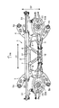
図1〜4に示される本発明の車両のサブフレーム構造の実施形態であるサブフレーム1は、二輪駆動(2WD)のうちの前輪二輪駆動(FF)の自動車の車体後部を支持するサブフレームを構成している。なお、図3における矢印FRは、車両前方の向きを示している(以下同様)。
(First embodiment)
A
このサブフレーム1は、フロント車幅方向メンバ2(第1車幅方向メンバ)およびリア車幅方向メンバ3(第2車幅方向メンバ)と、それらの左右両端に連結される一対の前後方向メンバ4、5と、一対の連結メンバ6、7と、一対の連結ブラケット8、9とを備えている。
The
また、このサブフレーム1には、マルチリンクサスペンション機構50が支持されている。マルチリンクサスペンション機構50は、複数のサスペンションアームを有するマルチリンク型サスペンションであり、サブフレーム1の左右両端において、アッパサスペンションアーム51と、ロアサスペンションアーム52と、リアロアアーム53と、スプリング54と、ダンパ55とをそれぞれ一対ずつ備えている。
In addition, a
フロント車幅方向メンバ2は、車幅方向D1(図1参照)に延びる部材であり、左右両端部において上下に離間したアッパアーム支持部10およびロアアーム支持部11を有しており、略X字状の形状をしている。
The front vehicle
アッパアーム支持部10のアーム支持孔10aには、アッパサスペンションアーム51の内側端部(サブフレーム1側の端部)がボルト等により上下に揺動自在に支持されている。一方、ロアアーム支持部11のアーム支持孔11aには、ロアサスペンションアーム52の内側端部がボルト等により上下に揺動自在に支持されている。
In the
アッパサスペンションアーム51およびロアサスペンションアーム52は、それぞれの外側端部(サブフレーム1に対して反対側の端部)が車輪Wを回転自在に支持する支持部材Sを上下に揺動自在に支持している。
Each of the
リア車幅方向メンバ3は、車幅方向D1(図2参照)に延びる部材であり、フロント車幅方向メンバ2から車体前後方向に間隔をおいて設けられている。
The rear vehicle
このリア車幅方向メンバ3には、車幅方向D1に延びる一対のリアロアアーム53がボルト等により上下に揺動自在に支持されている。また、リア車幅方向メンバ3の下面側の中央付近には、補強ブラケット12(図3参照)が溶接されている。
A pair of rear
リアロアアーム53は、その外側端部が支持部材Sに取り付けられ、その内側端部がリア車幅方向メンバ3に取り付けられている。このリアロアアーム53には、スプリング54が取り付けられている。スプリング54は、その下端部がリアロアアーム53のスプリング受け部53aに受け入れられ、その上端部が車体(図示せず)に取り付けられている。一方、ダンパ55は、その下端部が支持部材Sに直接取り付けられ、その上端部が車体(図示せず)に取り付けられている。
The rear
一対の前後方向メンバ4、5は、アッパアーム支持部10とロアアーム支持部11との間に取り付けられ、フロント車幅方向メンバ2及びリア車幅方向メンバ3の左側端部同士及び右側端部同士をそれぞれ連結して車体前後方向D2(図3参照)に延びる部材である。
The pair of front and
前後方向メンバ4、5は、フロント車幅方向メンバ2におけるアッパアーム支持部10とロアアーム支持部11との間に形成された凹部31に挿入された状態でフロント車幅方向メンバ2に接合され、それとともにリア車幅方向メンバ3の両端に形成された凹部32に挿入された状態でリア車幅方向メンバ3に接合されている。
The front and
前後方向メンバ4、5のそれぞれの前端部および後端部には、マウント部4a、4b、5a、5bが設けられている。これらの4a、4b、5a、5bを介して、サブフレーム1が車体(図示せず)に取り付けられている。
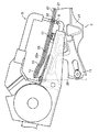
また、図4に示されるように、前後方向メンバ4、5におけるアッパアーム支持部10との連結部位は、後上方(図4における右上)に傾斜している。この構成によって、サブフレーム1の前後方向の剛性が向上している。
As shown in FIG. 4, the connecting portion of the front and
また、図3〜7に示されるように、一対の連結メンバ6、7は、フロント車幅方向メンバ2における左右両側のロアアーム支持部11またはその近傍部分とリア車幅方向メンバ3の中間部分との間を連結している。
As shown in FIGS. 3 to 7, the pair of connecting
フロント車幅方向メンバ2とリア車幅方向メンバ3は、それらの下部に荷重がかかりやすいが、それらの下部同士を一対の連結メンバ6、7で部分的に強固に連結しているので、前後方向の剛性を向上している。
Although the front vehicle
また、連結メンバ6、7は、図3の車幅方向D1で見て車幅方向内側に傾斜して配置されている。具体的には、フロント車幅方向メンバ2との連結部分では間隔が広く、リア車幅方向メンバ3との連結部分では間隔が狭くなるように配置されている。これにより、自動車の旋回時による荷重を、荷重が集中するサブフレーム1の下部で効果的に受け止めることができる。
Further, the connecting
さらに、図1〜4および図6〜8に示されるように、一対の連結ブラケット8、9は、フロント車幅方向メンバ2のアッパアーム支持部10またはその近傍部分と、前後方向メンバ4,5との間をそれぞれ連結している。
Further, as shown in FIGS. 1 to 4 and FIGS. 6 to 8, the pair of connecting
連結ブラケット8、9は、連結メンバ6、7よりも長さも短く、剛性も低く、かつ軽量の部材である。この連結ブラケット8、9は、アッパアーム支持部10とその近くに配置された前後方向メンバ4,5との間を連結メンバ6、7より短い距離で斜めに連結している。
The
また、図6〜8に示されるように、連結ブラケット8、9の前側には、それぞれ三角形の爪状の突起38が形成されている。
Also, as shown in FIGS. 6 to 8, triangular claw-
そして、図6に示されるように、車幅方向外側の突起38は、フロント車幅方向メンバ2の上面と後面とに沿った形状に形成されている。また図7に示されるように連結ブラケット8、9の後側部位は、前後方向メンバ4,5の上面および車幅方向内側の側面とに連結される形状に形成されている。
この構成によって、フロント車幅方向メンバ2の後方側及び前後方向メンバ4,5との溶接の際に接合面積が増えるので、車両前後方向の剛性がさらに向上している。
And as FIG. 6 shows, the
With this configuration, the joint area increases when welding the rear side of the front vehicle
また、連結ブラケット8、9の前側の車幅方向外側の突起38と前側車幅方向メンバ2との接合面積が増える一方、連結ブラケット8、9の後側部位と前後方向メンバ4,5の車幅方向内側の側面との接合面積が増えることにより、連結ブラケット8、9は車両後方且つ車幅方向内側に向う方向に荷重を伝達し易くなっている。
Further, the joint area between the front vehicle width direction
さらに、連結ブラケット8、9の上面には、埋込みボルト39が設けられている。この埋込みボルト39を介して、スタビライザ35のバー37を回転自在に取り付けるためのブラケット36(図2および図4参照)が固定されている。
Further, embedded
この構成によれば、荷重が集中するフロント車幅方向メンバ2の下側を構成するロアアーム支持部11の付近を、連結メンバ6、7によってリア車幅方向メンバと強固に連結して前後方向の剛性を向上させている。それとともに、下側と比較して相対的に荷重がかからないフロント車幅方向メンバ2の上側を構成するアッパアーム支持部10の付近とその近くに配置された前後方向メンバ4、5との間の短い距離(連結ブラケット8、9よりもきわめて短い距離)を、連結ブラケット8、9によって連結している。
According to this configuration, the vicinity of the lower
これにより、荷重の大きさに対して構造を最適化することにより、前後方向においての剛性を向上させることができ、軽量化を達成することが可能である。 Thereby, by optimizing the structure with respect to the magnitude of the load, the rigidity in the front-rear direction can be improved, and weight reduction can be achieved.
また、このように連結ブラケット8、9でフロント車幅方向メンバ2の上側を支持する構造では、構造の簡略化が可能になり、軽量化および生産性の向上を図ることが可能である。
Further, in the structure in which the upper side of the front vehicle
また、図5〜6に示されるように、フロント車幅方向メンバ2は、車幅方向に延びる一対の断面コ字状のパネル21、22を互いの端縁付近を接合して組み合わせた中空体である。具体的には、図6に示されるように、アッパアーム支持部10およびロアアーム支持部11の車幅方向外側には、連続した開口26が形成されている。しかも、フロント車幅方向メンバ2の中間部分の前面2aおよび後面2bは、閉じた平面を有しており、かつ、一対の断面コ字状のパネル21、22は、上面23および下面24のみで互いにスポット溶接で仮溶接された後にシーム溶接されている。同様に、リア車幅方向メンバ3も、2枚のパネル28、29を接合して中空体形状に形成されている。
As shown in FIGS. 5 to 6, the front vehicle
この構成によれば、フロント車幅方向メンバ2およびリア車幅方向メンバ3は、中空体であり、かつ、その中間部分の前面2aおよび後面2bが閉じた平面を有しているので、中央部が剛くなり、軽量化を達成することができる。
According to this configuration, the front vehicle
しかも、フロント車幅方向メンバ2の両端部は、その車幅方向外側において、アッパアーム支持部10からロアアーム支持部11にかけて連続した開口26を大きく形成することが可能である。そのため、図10に示されるように、仮スポット溶接用の溶接ガンGの電極Eを開口26に挿入して車幅方向中央近傍までスポット仮溶接をすることが可能である。また、図10には、パネル21、22の重ね合わせた部分における複数のスポット溶接部分33が示されている。
In addition, both ends of the front vehicle
ここで、図8〜9に示されるように、仮接合のためのスポット溶接部分33は、フロント車幅方向メンバ2を構成するパネル21、22を重ね合せた部分のうち、パネル22の切起し部分22aにパネル21の先端が突き当たった付近に形成される。一方、パネル21と22とをシーム溶接により強固に接合するためのシーム溶接部分34は、スポット溶接部分33から離間したパネル22の先端付近に形成される。これにより、生産性を向上しつつ、溶接箇所が増えることによって断面係数を向上することができる。しかも、シーム溶接部分34は、スポット溶接部分33から離れているので、スポット仮溶接およびその後のシーム溶接を行ってもパネル21、22への熱による影響(変形や剛性低下等)が少ない。
Here, as shown in FIGS. 8 to 9, the spot welded
また、このように前後のパネル21、22を重ね合わせて接合するフランジレス構造なので、溶接しろのためにフランジを設ける必要がなくなり、材料歩留まりおよび軽量化の向上が可能である。
Further, since the front and
しかも、本実施形態では、図8に示されるように、前後パネル21、22の位置決めのための切起し部分22aおよびスポット溶接部分33は、両側の連結ブラケット8、9の近傍に位置しているので、前側のパネル21の荷重を連結ブラケット8、9に伝達するのに寄与する。
In addition, in the present embodiment, as shown in FIG. 8, the cut-and-raised
なお、リア車幅方向メンバ3も、フロント車幅方向メンバ2と同様の溶接方法により、製造されている。
The rear vehicle
また、図3〜4に示されるように、フロント車幅方向メンバ2は、ロアアーム支持部11において、リア車軸方向メンバ3に対して反対側に車体前後方向D2に屈曲して延び、前後方向メンバ4、5と接合されるフランジ部25を有している。
Also, as shown in FIGS. 3 to 4, the front vehicle
この構成によれば、フランジ部25により前後方向メンバ4、5を支持することができ、それにより、開口26を狭めることなくフロント車幅方向メンバ2の前後方向の剛性をさらに向上することができる。
According to this configuration, the front-
さらに、フロント車幅方向メンバ2は、図1に示されるように、その左側のアッパアーム支持部10と右側のロアアーム支持部11との間で略対角線的に荷重を受け止めると共にその右側のアッパアーム支持部10と左側のロアアーム支持部11との間で荷重を対角線L1、L2上に荷重を受け止める構造(いわば、タスキ掛け構造)を有している。なお、図1における符号27は、ジャッキポイントであり、上記のタスキ掛け構造に影響を与えるものではない。
Further, as shown in FIG. 1, the front vehicle
このようにフロント車幅方向メンバ2をタスキ掛け形状にすることにより、車幅方向D1の剛性を向上することが可能である。具体的には、接地点同相の右旋回時には、左側のロアアーム支持部11にフロント車幅方向メンバ2を圧縮する荷重が加わる一方、その対角線上L2の右側のアッパアーム支持部10にもフロント車幅方向メンバ2を圧縮する荷重が加わる。また、左側のアッパアーム支持部10にフロント車幅方向メンバ2を引っ張る荷重が加わる一方、その対角線L1上の右側のロアアーム支持部11にもフロント車幅方向メンバ2を引っ張る荷重が加わる。このような車幅方向に加わる荷重に対して、フロント車幅方向メンバ2は、対角線L1、L2上に荷重を受け止めるので、左右のサスペンションアーム51、52に加わる荷重をフロント車幅方向メンバ2が効率的に受け止め、それにより、左右の荷重同士を有効に打ち消すことができる。
Thus, the rigidity in the vehicle width direction D1 can be improved by forming the front vehicle
さらに、図1に示されるように、タスキ掛けにX字状に結ぶ対角線L1とL2との交点Pは、フロント車幅方向メンバ2の中央に位置するのが好ましい。具体的には、フロント車幅方向メンバ2の中央部断面中心として、図1では、フロント車幅方向メンバ2の左右両端におけるアッパアーム支持部10のアーム支持孔10aとロアアーム支持部11のアーム支持孔11aとの中間位置を通る中心線L3が示されており、この中心線L3が交点Pの直上またはその近傍を通るのが好ましい。これにより、車幅方向および前後方向の剛性を向上することができる。
Furthermore, as shown in FIG. 1, it is preferable that the intersection P between the diagonal lines L1 and L2 that are connected in an X shape to the hanger is located at the center of the front vehicle
(サブフレーム1の製造方法の説明)
つぎに本実施形態のサブフレーム1の製造方法について説明する。
(Description of manufacturing method of subframe 1)
Next, a method for manufacturing the
まず、図5に示されるように、フロント車幅方向メンバ2のそれぞれ断面コ字状の前パネル21と後パネル22とをそれぞれの端縁同士を当接させて支持するとともに、リア車幅方向メンバ3の前パネル28と後パネル29とを当接させて支持する。このとき、リア車幅方向メンバ3の下面側に補強ブラケット12も当接させて支持する。そして、フロント車幅方向メンバ2と、リア車幅方向メンバ3と、連結メンバ7、8とを互いに当接させて支持する。
First, as shown in FIG. 5, the
このとき、フロント車幅方向メンバ2の各アーム支持部10、11のアーム支持孔10a、11aは、製造時にフロント車幅方向メンバ2の位置決め孔として用いられるので、それにより、製造時の誤差を小さくすることができる。
At this time, the arm support holes 10a and 11a of the respective
つぎに、図6に示されるように、各メンバ2、3、6、7およびそれらの間をスポット溶接により一括して仮接合して中間体40(図6参照)を仮止めする。
Next, as shown in FIG. 6, the
つぎに、図6に示されるように、各メンバ2、3、6、7の間の連続接合部位を一括してシーム溶接して中間体40(図6参照)を形成する。
Next, as shown in FIG. 6, the intermediate joint 40 (see FIG. 6) is formed by seam welding the continuous joint portions between the
つぎに、中間体40に、左右一対の前後方向メンバ4、5と連結ブラケット8、9とを位置決めして仮止めする。
Next, the pair of left and right front-
その後、前後方向メンバ5、6および連結ブラケット8、9と中間体40とをそれらの接合部位を一括してシーム溶接することにより、サブフレーム1が完成する。
Thereafter, the
以上のような製造方法により、スポット仮溶接による中間体40の一括組立により、工程数を大幅に削減することができ、生産ラインをスリム化することができる。
By the manufacturing method as described above, the number of steps can be greatly reduced by the batch assembly of the
すなわち、従来の製造方法では、各メンバ2、3、6、7をそれぞれ、スポット仮溶接およびシーム溶接してメンバ単体ごとに溶接を終了した後、さらに、各メンバ2,3,6、7の間をスポット仮溶接およびシーム溶接して中間体40を製造し、その後、中間体40と前後方向メンバ5、6および連結ブラケット8、9との間のシーム溶接を行っていたので、非常に工程数が多かった。
That is, in the conventional manufacturing method, after each
しかし、上記の本実施形態の製造方法では、メンバ2、3、6、7を中間体40の状態までスポット溶接で一括して仮止めし、さらに一括してシーム溶接することにより、中間体40を形成するので、大幅に工程数を削減でき、生産ラインをスリム化できる。
However, in the manufacturing method of the present embodiment, the
しかも、個々のメンバ2、3、6、7の溶接時に生じる誤差が、サブフレーム1の全体の誤差に蓄積するおそれも少なくなる。
In addition, the error that occurs when welding the
(第2実施形態)
上記実施形態では、FF用のサブフレームを例に挙げて説明しているが、本発明はこれに限定されるものではなく、四輪駆動(4WD)用のサブフレームについても本発明を適用することが可能である。
(Second Embodiment)
In the above embodiment, the subframe for FF is described as an example, but the present invention is not limited to this, and the present invention is also applied to a subframe for four-wheel drive (4WD). It is possible.
すなわち、図11〜15に示される本発明の車両のサブフレーム構造の他の実施形態であるサブフレーム101は、四輪駆動(4WD)用の自動車の車体後部を支持するサブフレームを構成している。
That is, the
このサブフレーム101は、一対のフロント車幅方向メンバ102およびリア車幅方向メンバ103と、それらの左右両端に連結される一対の前後方向メンバ104、105と、一対の連結メンバ106、107と、一対の連結ブラケット108、109とを備えている。
The
また、このサブフレーム101には、上述のマルチリンクサスペンション機構50(図1参照)が支持される。
Further, the
フロント車幅方向メンバ102は、車幅方向D1に延びる部材であり、左右両端部において上下に離間したアッパアーム支持部110およびロアアーム支持部111を有しており、略X字状の形状をしている。
The front vehicle
アッパアーム支持部110のアーム支持孔110aには、アッパサスペンションアーム51(図1参照)の内側端部がボルト等により上下に揺動自在に支持され、ロアアーム支持部111のアーム支持孔111aには、ロアサスペンションアーム52(図1参照)の内側端部がボルト等により上下に揺動自在に支持される。
The inner end portion of the upper suspension arm 51 (see FIG. 1) is supported by the
なお、4WD用のサブフレーム1の場合、車体後部には、後輪を駆動させるためのリアデファレンシャルユニットおよびドライブシャフトが配置される関係上、フロント車幅方向メンバ102の中央下部には、空間部102aが形成されている。
In the case of the
なお、図11〜12の符号130は、リア側のデファレンシャルユニットを支持するためのリアデフ支持ブラケットを示している。
In addition, the code |
リア車幅方向メンバ103は、車幅方向D1に延びる部材であり、フロント車幅方向メンバ102から車体前後方向に間隔をおいて設けられている。
The rear vehicle
このリア車幅方向メンバ103には、車幅方向D1に延びる一対のリアロアアーム53(図1参照)がボルト等により上下に揺動自在に支持される。また、リア車幅方向メンバ103の下面側の中央付近には、補強ブラケット112が溶接されている。
A pair of rear lower arms 53 (see FIG. 1) extending in the vehicle width direction D1 are supported by the rear vehicle
一対の前後方向メンバ104、105は、アッパアーム支持部110とロアアーム支持部111との間に取り付けられ、フロント車幅方向メンバ102及びリア車幅方向メンバ103の左側端部同士及び右側端部同士をそれぞれ連結して車体前後方向D2(図3参照)に延びる部材である。
The pair of front and
前後方向メンバ104、105は、フロント車幅方向メンバ102におけるアッパアーム支持部110とロアアーム支持部111との間に形成された凹部131に挿入された状態でフロント車幅方向メンバ102に接合され、それとともにリア車幅方向メンバ103の両端に形成された凹部132に挿入された状態でリア車幅方向メンバ103に接合されている。
The front and
この4WD用の前後方向メンバ104、105は、上述のFF用の前後方向メンバ4、5(図1参照)よりも上方に位置しているので、アッパアーム支持部110は、前後方向メンバ104、105を側方から組み付けるために、図1のアッパアーム支持部10よりも細くなっている。そこで、補強のために、アッパアーム支持部110と前後方向メンバ104、105の上部との間には、補強ブラケット141(図13参照)が設けられている。
Since the 4WD front-
なお、補強ブラケット141,141は、前後方向メンバ104,105の上面および車幅方向D1の外側面と接合されている。
The reinforcing
さらに、図14に示されるように、前後方向メンバ104、105の下部とリア車幅方向メンバ103との間には、補強ブラケット142が設けられている。
Further, as shown in FIG. 14, a reinforcing
また、図11〜12および図15に示されるように、一対の連結メンバ106、107は、フロント車幅方向メンバ102における左右両側のロアアーム支持部111とリア車幅方向メンバ103の左右両端付近との間を連結している。また、図15に示されるように、連結メンバ107のフランジ部107aは、フロント車幅方向メンバ102の下面に接合しているので、さらに前後方向の剛性を向上させている。
Further, as shown in FIGS. 11 to 12 and FIG. 15, the pair of connecting
フロント車幅方向メンバ102とリア車幅方向メンバ103は、それらの下部に荷重がかかりやすいが、それらの下部同士を一対の連結メンバ106、107で部分的に強固に連結しているので、前後方向の剛性を向上している。
The front vehicle
また、連結メンバ106、107は、図12の車幅方向D1で見て車幅方向内側に傾斜して配置されているので、自動車の旋回時による荷重を、荷重が集中するサブフレーム101の下部で効果的に受け止めることができる。
Further, since the connecting
さらに、一対の連結ブラケット108、109は、フロント車幅方向メンバ102のアッパアーム支持部110またはその近傍部分と、前後方向メンバ104、105との間をそれぞれ連結している。
Further, the pair of
連結ブラケット108、109は、連結メンバ106、107よりも長さも短く、軽量の部材である。この連結ブラケット108、109は、アッパアーム支持部110と前後方向メンバ104、105との間の短い距離を斜めに連結している。
The
また、連結ブラケット108、109の前側には、それぞれ突起138が形成されているので、フロント車幅方向メンバ102の後方側との溶接の際に接合面積が増えるので、前後方向の剛性がさらに向上している。
Further, since the
さらに、連結ブラケット108、109の上面には、スタビライザ固定用のブラケット36(図2参照)を取り付けるための埋込みボルト139が設けられている。
Further, embedded
図11〜15に示される4WD用のサブフレーム101においても、荷重が集中するフロント車幅方向メンバ102の下側を構成するロアアーム支持部111の付近を、連結メンバ106、107によってリア車幅方向メンバ103と強固に連結して前後方向の剛性を向上させている。それとともに、下側と比較して相対的に荷重がかからないフロント車幅方向メンバ102の上側を構成するアッパアーム支持部110の付近とその近くに配置された前後方向メンバ104、105との間の短い距離(連結ブラケッ108、109よりもきわめて短い距離)を、連結ブラケット108、109によって連結している。
Also in the
これにより、荷重の大きさに対して構造を最適化することにより、前後方向においての剛性を向上させることができ、軽量化を達成することが可能である。 Thereby, by optimizing the structure with respect to the magnitude of the load, the rigidity in the front-rear direction can be improved, and weight reduction can be achieved.
これにより、荷重の大きさに対して構造を最適化することにより、前後方向においての剛性を向上させることができ、軽量化を達成することが可能である。 Thereby, by optimizing the structure with respect to the magnitude of the load, the rigidity in the front-rear direction can be improved, and weight reduction can be achieved.
また、このように連結ブラケット108、109でフロント車幅方向メンバ102の上側を支持する構造では、構造の簡略化が可能になり、軽量化および生産性の向上を図ることが可能である。
Further, with the structure in which the upper side of the front vehicle
さらに、4WD用のサブフレーム101においても、上側の左右のアーム支持孔110a,110aを通るラインL5と、下側の左右のアーム支持孔111a,111aを通るラインL6の間に、フロント車幅方向メンバ102の車幅方向中心部位における断面中心Qが設けられ、この断面中心Qと各アーム支持孔110a、111aとが直線的に連結(すなわち、空間部102aなどを横切ったり迂回しないで直線的に連結)されることで、略対角線的に構成されていることにより、フロント車幅方向メンバ102のアッパアーム支持部110およびロアアーム支持部111をタスキ掛けの配置(X字状の配置)にすることができるので、車幅方向D1の剛性を向上することが可能である。
Further, in the
また、この4WD用のサブフレーム101も、上述のFF用のサブフレーム1(図1参照)と同じ工程で製造することができるので、これらの生産ラインを共通化することも容易である。
Further, the
(第3実施形態)
上記の図11〜15に示される4WD用のサブフレーム101では、フロント車幅方向メンバ102のアッパアーム支持部110が他の部材とともに一体形成されているが、本発明はこれに限定されるものではなく、別部材で形成してもよい。
(Third embodiment)
In the
すなわち、図16〜17に示されるように、フロント車幅方向メンバ102のアッパアーム支持部110の少なくとも一部(図16〜17の例では全部)が、フロント車幅方向メンバ102の他の部分とは別の部材143からなり、前後方向メンバ104、105の上面から車幅方向D1における外側(前後方向メンバ104、105が互いに離反する方向の側)にかけて接合されている。
That is, as shown in FIGS. 16 to 17, at least a part (the whole in the example of FIGS. 16 to 17) of the upper
アッパアーム支持部110を構成する部材143は、前後方向メンバ104、105をフロント車幅方向メンバ102の左右両側の所定位置に位置決めされた後に、フロント車幅方向メンバ102の他の部材および前後方向メンバ104、105に対して、後付けで溶接されている。
The
この構成によれば、アッパアーム支持部110を前後方向メンバ104、105と上下方向に重ねて配設できると共に、前後方向メンバ104、105との接合面積を拡大することができるので、ねじれ剛性を向上できる。また、設計自由度も向上する。
According to this configuration, the upper
なお、上記の第1〜第3実施形態では、自動車を例に挙げて説明したが、本発明はこれに限定されるものではなく、本発明の車両のサブフレーム構造は、複数のサスペンションを有する車両であれば、自動車以外の車両の車体にも適用することが可能である。 In the first to third embodiments described above, the automobile is described as an example. However, the present invention is not limited to this, and the vehicle subframe structure of the present invention includes a plurality of suspensions. If it is a vehicle, it is possible to apply also to the vehicle body of vehicles other than a motor vehicle.
1 サブフレーム
2 フロント車幅方向メンバ
2a 前面
2b 後面
3 リア車幅方向メンバ
4、5 前後方向メンバ
4a、4b、5a、5b マウント部
6、7 連結メンバ
8、9 連結ブラケット
10 アッパアーム支持部
10a アーム支持孔
11 ロアアーム支持部
11a アーム支持孔
12 補強ブラケット(リア車幅方向メンバ下側)
21、22 パネル
23 上面
24 下面
25 フランジ部
26 開口
27 ジャッキポイント
28、29 パネル
31 凹部(フロント車幅方向メンバ側)
32 凹部(リア車幅方向メンバ側)
33 スポット溶接部分
34 シーム溶接部分
35 スタビライザ
36 ブラケット
37 バー
38 突起
40 中間体
50 マルチリンクサスペンション機構
51 アッパサスペンションアーム
52 ロアサスペンションアーム
53 リアロアアーム
53a スプリング受け部
54 ダンパ
55 スプリング
101 サブフレーム
102 フロント車幅方向メンバ
103 リア車幅方向メンバ
104、105 前後方向メンバ
110 アッパアーム支持部
111 ロアアーム支持部
143 部材
DESCRIPTION OF
21, 22
32 Recess (Rear vehicle width direction member side)
33 Spot welded
Claims (5)
左右両端部において上下に離間したアッパアーム支持部およびロアアーム支持部を有し、車幅方向に延びる第1車幅方向メンバと、
前記第1車幅方向メンバから車体前後方向に間隔をおいて設けられ、車幅方向に延びる第2車幅方向メンバと、
前記アッパアーム支持部とロアアーム支持部との間に取り付けられ、前記第1及び第2車幅方向メンバの左側端部同士及び右側端部同士をそれぞれ連結して車体前後方向に延びる一対の前後方向メンバと、
前記第1車幅方向メンバの前記ロアアーム支持部またはその近傍部分と、前記第2車幅方向メンバとを連結する連結メンバと、
前記第1車幅方向メンバのアッパアーム支持部またはその近傍部分と、前記一対の前後方向メンバとの間をそれぞれ連結する一対の連結部と
を備えている、
車両のサブフレーム構造。 A sub-frame structure of a vehicle that supports a suspension arm of a multi-link suspension,
A first vehicle width direction member having an upper arm support portion and a lower arm support portion that are vertically spaced at both left and right end portions and extending in the vehicle width direction;
A second vehicle width direction member provided in the vehicle longitudinal direction from the first vehicle width direction member and extending in the vehicle width direction;
A pair of front-rear members that are attached between the upper arm support portion and the lower arm support portion and extend in the vehicle front-rear direction by connecting the left end portions and the right end portions of the first and second vehicle width direction members, respectively. When,
A connecting member that connects the lower arm support portion of the first vehicle width direction member or a portion in the vicinity thereof and the second vehicle width direction member;
An upper arm support portion of the first vehicle width direction member or a portion near the upper arm support portion and a pair of connection portions that connect the pair of front and rear direction members, respectively.
Sub-frame structure of the vehicle.
請求項1に記載の車両のサブフレーム構造。 The first vehicle width direction member has a flange portion that is bent and extends in the lower arm support portion so as to be opposite to the second vehicle width direction member, and is joined to the front-rear direction member.
The vehicle sub-frame structure according to claim 1.
請求項1または2に記載の車両のサブフレーム構造。 At least a part of the upper arm support portion of the first vehicle width direction member is made of a member different from other portions of the first vehicle width direction member, and is joined from the upper surface of the front / rear direction member to the vehicle width direction outer side. ing,
The vehicle sub-frame structure according to claim 1 or 2.
請求項1から3のいずれかに記載の車両のサブフレーム構造。 The first vehicle width direction member receives the load substantially diagonally between the left upper arm support portion and the right lower arm support portion and between the right upper arm support portion and the left lower arm support portion. It has a structure that receives the load almost diagonally with
The vehicle subframe structure according to any one of claims 1 to 3.
請求項1から4のいずれかに記載の車両のサブフレーム構造。 The connecting member is disposed to be inclined inward in the vehicle width direction toward the second vehicle width direction member.
The sub-frame structure for a vehicle according to any one of claims 1 to 4.
Priority Applications (5)
| Application Number | Priority Date | Filing Date | Title |
|---|---|---|---|
| JP2010077382A JP5299337B2 (en) | 2010-03-30 | 2010-03-30 | Subframe structure of vehicle |
| PCT/JP2011/001889 WO2011122012A1 (en) | 2010-03-30 | 2011-03-30 | Sub-frame structure of vehicle and manufacturing method thereof |
| US13/636,289 US8511696B2 (en) | 2010-03-30 | 2011-03-30 | Sub-frame structure of vehicle and manufacturing method thereof |
| CN201180014559.4A CN102803048B (en) | 2010-03-30 | 2011-03-30 | Sub-frame structure of vehicle and manufacturing method thereof |
| DE112011101174T DE112011101174T5 (en) | 2010-03-30 | 2011-03-30 | Subframe construction of a vehicle and manufacturing method thereof |
Applications Claiming Priority (1)
| Application Number | Priority Date | Filing Date | Title |
|---|---|---|---|
| JP2010077382A JP5299337B2 (en) | 2010-03-30 | 2010-03-30 | Subframe structure of vehicle |
Publications (2)
| Publication Number | Publication Date |
|---|---|
| JP2011207351A JP2011207351A (en) | 2011-10-20 |
| JP5299337B2 true JP5299337B2 (en) | 2013-09-25 |
Family
ID=44711767
Family Applications (1)
| Application Number | Title | Priority Date | Filing Date |
|---|---|---|---|
| JP2010077382A Active JP5299337B2 (en) | 2010-03-30 | 2010-03-30 | Subframe structure of vehicle |
Country Status (5)
| Country | Link |
|---|---|
| US (1) | US8511696B2 (en) |
| JP (1) | JP5299337B2 (en) |
| CN (1) | CN102803048B (en) |
| DE (1) | DE112011101174T5 (en) |
| WO (1) | WO2011122012A1 (en) |
Families Citing this family (15)
| Publication number | Priority date | Publication date | Assignee | Title |
|---|---|---|---|---|
| US8616567B2 (en) * | 2010-06-30 | 2013-12-31 | Mazda Motor Corporation | Vehicle suspension apparatus |
| JP5807519B2 (en) * | 2011-11-11 | 2015-11-10 | マツダ株式会社 | Rear body structure of automobile |
| JP5987341B2 (en) * | 2012-02-17 | 2016-09-07 | マツダ株式会社 | Rear subframe body mounting structure |
| DE102012020612A1 (en) * | 2012-10-19 | 2014-04-24 | Audi Ag | Axle carrier for a motor vehicle |
| JP5713033B2 (en) * | 2013-01-21 | 2015-05-07 | トヨタ自動車株式会社 | Vehicle structure |
| DE102013002710A1 (en) * | 2013-02-16 | 2014-08-21 | Audi Ag | Wheel suspension for a motor vehicle |
| JP5840161B2 (en) * | 2013-03-04 | 2016-01-06 | 本田技研工業株式会社 | Dissimilar material joining method |
| DE102013005682C5 (en) * | 2013-04-03 | 2021-03-11 | Audi Ag | Subframe for a multi-link axle of a motor vehicle |
| DE102013011562A1 (en) | 2013-07-11 | 2015-01-15 | Audi Ag | Subframe for a motor vehicle |
| BR112016000353B1 (en) * | 2013-07-11 | 2022-08-16 | Honda Motor Co., Ltd. | AUXILIARY CHASSIS FOR VEHICLE |
| CA2934608C (en) * | 2013-12-27 | 2018-06-05 | Honda Motor Co., Ltd. | Sub-frame structure |
| RU2656929C2 (en) * | 2014-03-31 | 2018-06-07 | Йорозу Корпорейшн | Suspension member and method of its manufacture |
| JP6102951B2 (en) * | 2015-01-16 | 2017-03-29 | マツダ株式会社 | Subframe structure of vehicle |
| JP6102952B2 (en) * | 2015-01-16 | 2017-03-29 | マツダ株式会社 | Subframe structure of vehicle |
| WO2020246044A1 (en) * | 2019-06-07 | 2020-12-10 | 株式会社ヨロズ | Cross member and subframe of suspension |
Family Cites Families (10)
| Publication number | Priority date | Publication date | Assignee | Title |
|---|---|---|---|---|
| JPH0735121B2 (en) * | 1987-04-14 | 1995-04-19 | マツダ株式会社 | Subframe structure of automobile |
| JP4038902B2 (en) * | 1998-11-16 | 2008-01-30 | マツダ株式会社 | Stabilizer mounting bracket structure |
| JP4701576B2 (en) * | 2001-09-28 | 2011-06-15 | マツダ株式会社 | Vehicle suspension system |
| US6755429B1 (en) * | 2003-05-06 | 2004-06-29 | Ford Global Technologies, Llc | Independent suspension for rear wheels of automotive vehicle |
| JP2006347338A (en) * | 2005-06-15 | 2006-12-28 | Mazda Motor Corp | Rear suspension device for automobile |
| JP2008168791A (en) * | 2007-01-12 | 2008-07-24 | Fuji Heavy Ind Ltd | Suspension cross member structure of automobile |
| JP5518344B2 (en) * | 2008-03-26 | 2014-06-11 | マツダ株式会社 | Vehicle suspension subframe structure |
| JP5141961B2 (en) * | 2008-03-26 | 2013-02-13 | マツダ株式会社 | Vehicle suspension subframe structure |
| EP2105329B1 (en) | 2008-03-26 | 2010-09-22 | Mazda Motor Corporation | Suspension subframe structure of vehicle |
| JP5146176B2 (en) * | 2008-07-30 | 2013-02-20 | マツダ株式会社 | Vehicle suspension subframe |
-
2010
- 2010-03-30 JP JP2010077382A patent/JP5299337B2/en active Active
-
2011
- 2011-03-30 US US13/636,289 patent/US8511696B2/en active Active
- 2011-03-30 WO PCT/JP2011/001889 patent/WO2011122012A1/en active Application Filing
- 2011-03-30 CN CN201180014559.4A patent/CN102803048B/en not_active Expired - Fee Related
- 2011-03-30 DE DE112011101174T patent/DE112011101174T5/en not_active Withdrawn
Also Published As
| Publication number | Publication date |
|---|---|
| WO2011122012A1 (en) | 2011-10-06 |
| US8511696B2 (en) | 2013-08-20 |
| DE112011101174T5 (en) | 2013-02-28 |
| US20130009375A1 (en) | 2013-01-10 |
| CN102803048B (en) | 2015-03-04 |
| JP2011207351A (en) | 2011-10-20 |
| CN102803048A (en) | 2012-11-28 |
Similar Documents
| Publication | Publication Date | Title |
|---|---|---|
| JP5299337B2 (en) | Subframe structure of vehicle | |
| US7871093B2 (en) | Torsion beam suspension | |
| JP2006315445A (en) | Bodywork of automobile | |
| KR101338966B1 (en) | Suspension device for automobile | |
| CN112124427A (en) | Vehicle structure of frame type vehicle | |
| JP5968971B2 (en) | Car body rear structure | |
| JP4923026B2 (en) | Suspension arm support structure | |
| JP2012046070A (en) | Front structure of vehicle | |
| JP2006315557A (en) | Bodywork of automobile | |
| JP2009184547A (en) | Damper housing structure for automobile | |
| JP2002166714A (en) | Suspension arm | |
| CN110920756B (en) | Front body structure of vehicle | |
| JP6331589B2 (en) | Trailing arm mounting structure | |
| JP5251339B2 (en) | Vehicle suspension subframe | |
| WO2013171828A1 (en) | Torsion beam type suspension | |
| JP6875679B2 (en) | Rear suspension structure of automobile | |
| JP2006193001A (en) | Triangular window reinforcing structure | |
| JP2010030533A (en) | Suspension sub frame for vehicle | |
| WO2023181197A1 (en) | Vehicle body structure | |
| CN114132380B (en) | Vehicle lower part structure | |
| JP5483546B2 (en) | Vehicle front structure | |
| JP7186812B2 (en) | suspension | |
| JP6947088B2 (en) | Torsion beam suspension | |
| JP4747134B2 (en) | Body front structure | |
| JP4457643B2 (en) | Vehicle suspension support structure |
Legal Events
| Date | Code | Title | Description |
|---|---|---|---|
| A621 | Written request for application examination |
Free format text: JAPANESE INTERMEDIATE CODE: A621 Effective date: 20120928 |
|
| TRDD | Decision of grant or rejection written | ||
| A01 | Written decision to grant a patent or to grant a registration (utility model) |
Free format text: JAPANESE INTERMEDIATE CODE: A01 Effective date: 20130521 |
|
| A61 | First payment of annual fees (during grant procedure) |
Free format text: JAPANESE INTERMEDIATE CODE: A61 Effective date: 20130603 |
|
| R150 | Certificate of patent or registration of utility model |
Ref document number: 5299337 Country of ref document: JP Free format text: JAPANESE INTERMEDIATE CODE: R150 Free format text: JAPANESE INTERMEDIATE CODE: R150 |