JP5293174B2 - Device management system and device management program - Google Patents
Device management system and device management program Download PDFInfo
- Publication number
- JP5293174B2 JP5293174B2 JP2008332772A JP2008332772A JP5293174B2 JP 5293174 B2 JP5293174 B2 JP 5293174B2 JP 2008332772 A JP2008332772 A JP 2008332772A JP 2008332772 A JP2008332772 A JP 2008332772A JP 5293174 B2 JP5293174 B2 JP 5293174B2
- Authority
- JP
- Japan
- Prior art keywords
- unit
- analysis
- communication protocol
- device management
- signal
- Prior art date
- Legal status (The legal status is an assumption and is not a legal conclusion. Google has not performed a legal analysis and makes no representation as to the accuracy of the status listed.)
- Expired - Fee Related
Links
Images

Classifications
-
- Y—GENERAL TAGGING OF NEW TECHNOLOGICAL DEVELOPMENTS; GENERAL TAGGING OF CROSS-SECTIONAL TECHNOLOGIES SPANNING OVER SEVERAL SECTIONS OF THE IPC; TECHNICAL SUBJECTS COVERED BY FORMER USPC CROSS-REFERENCE ART COLLECTIONS [XRACs] AND DIGESTS
- Y02—TECHNOLOGIES OR APPLICATIONS FOR MITIGATION OR ADAPTATION AGAINST CLIMATE CHANGE
- Y02D—CLIMATE CHANGE MITIGATION TECHNOLOGIES IN INFORMATION AND COMMUNICATION TECHNOLOGIES [ICT], I.E. INFORMATION AND COMMUNICATION TECHNOLOGIES AIMING AT THE REDUCTION OF THEIR OWN ENERGY USE
- Y02D10/00—Energy efficient computing, e.g. low power processors, power management or thermal management
Landscapes
- Computer And Data Communications (AREA)
Description
本発明は、フィールド機器等の各種機器を管理する機器管理システム及び機器管理プログラムに関する。 The present invention relates to a device management system and a device management program for managing various devices such as field devices.
近年、プラントは、生産力の向上、生産効率の向上等のために大規模化・統合化が図られており、分散制御システム(DCS:Distributed Control System)を用いて高度に自動化されて操業されるのが一般的である。このようなプラントには様々なメーカーから提供されるフィールド機器等の各種機器(以下、単に「機器」という)が設置されており、温度、圧力、流量等の測定が自動的に行われるとともに、その測定結果が収集されて一元管理されている。 In recent years, plants have been scaled up and integrated in order to improve production capacity and production efficiency, etc., and have been highly automated and operated using a distributed control system (DCS). It is common. In such a plant, various devices such as field devices (hereinafter simply referred to as “devices”) provided by various manufacturers are installed, and the temperature, pressure, flow rate, and the like are automatically measured. The measurement results are collected and managed centrally.
一般的に、以上の機器はフィールドバス等のシリアルバス(以下、単に「バス」という)に接続されており、このバスを介して機器に対する制御が行われるとともに、機器で測定されたデータが収集される。ここで、上記のバスの規格には様々な規格が存在するが、バスがフィールドバスである場合には、ファンデーションフィールドバス(Foundation Fieldbus:登録商標)、HART(Highway Addressable Remote Transducer:登録商標)、プロフィバス(PROFIBUS:登録商標)、又はBRAIN等の規格が存在する。 In general, the above devices are connected to a serial bus such as a field bus (hereinafter simply referred to as “bus”), and the devices are controlled via this bus, and data measured by the devices is collected. Is done. Here, there are various standards for the above bus. When the bus is a field bus, Foundation Fieldbus (Foundation Fieldbus: registered trademark), HART (Highway Addressable Remote Transducer: registered trademark), There are standards such as PROFIBUS (registered trademark) or BRAIN.
以上のバスに接続された機器の管理は、専用の機器管理ツール(機器の設定・調整や機器で測定されたデータの収集を行うための専用のツール)がインストールされたコンピュータ(機器管理装置)を用いて行われる。この機器管理装置をバスに接続して、バスに接続された機器との間の通信を可能にするために変復調装置(バスがフィールドバスである場合には所謂フィールドバスモデム)が用いられる。 Management of devices connected to the above buses is a computer (device management device) with a dedicated device management tool (a dedicated tool for setting / adjusting devices and collecting data measured by devices) installed It is done using. A modem device (a so-called field bus modem when the bus is a field bus) is used to connect the device management device to the bus and enable communication with the device connected to the bus.
ここで、上記のモデムで用いられる通信プロトコルが、接続されるバスで用いられる通信プロトコルと一致しない場合には、機器と機器管理装置との間で通信を行うことができない。このため、プラント内に異なる規格のバスが混在する場合には、バスの規格に対応したモデムをバスの種類毎に用意するか、或いは1台で複数のバスの規格に対応しているモデムを使用する必要がある。 Here, when the communication protocol used by the modem does not match the communication protocol used by the connected bus, communication between the device and the device management apparatus cannot be performed. For this reason, when buses with different standards are mixed in the plant, a modem corresponding to the bus standard is prepared for each type of bus, or a single modem that supports multiple bus standards is prepared. Need to use.
尚、従来のフィールドバスモデムの詳細については、例えば以下の特許文献1を参照されたい。
ところで、従来のモデムは、以下の(1)〜(6)に示すような様々な問題があった。
(1)複数種類のバスが混在する場合には、そのバスの種類の分だけモデムを用意する必要があり、管理や操作に支障をきたすことがある。
(2)バスの仕様が変更された場合又はモデムの機能改善が行われた場合には、モデムの交換又はモデム内に存在するファームウェアの更新等のメンテナンスを行う必要があり、ユーザに繁雑な作業が強いられる。
(3)新しい種類のバスが追加された場合には、そのバスに対応可能なモデムを購入する必要がある。
By the way, the conventional modem has various problems as shown in the following (1) to (6).
(1) When a plurality of types of buses coexist, it is necessary to prepare modems for the number of bus types, which may hinder management and operation.
(2) When the bus specification is changed or when the modem function is improved, maintenance such as replacement of the modem or updating of firmware existing in the modem needs to be performed. Is forced.
(3) When a new type of bus is added, it is necessary to purchase a modem that can handle the bus.
(4)バスを介した通信が正常に行われない場合には、バスの通信状況を診断する特殊な診断装置を別途用意する必要がある。これは、モデム内に複雑な診断を実現するファームウェアを搭載することが一般的には困難なためである。つまり、複雑な機能を追加することで、モデムの消費電力が上昇して電力不足、バッテリの短寿命化、及び寸法の増大等を招いてしまうという不具合が生じてしまう。また、防爆が求められる環境で使用されるモデムについては、上記の機能を追加することで防爆規定を満たさなくなる可能性がある。 (4) When communication via the bus is not normally performed, it is necessary to prepare a special diagnostic device for diagnosing the bus communication status. This is because it is generally difficult to install firmware that realizes complex diagnosis in the modem. That is, adding a complicated function causes a problem that the power consumption of the modem increases, leading to a shortage of power, a short battery life, and an increase in dimensions. In addition, for modems used in environments where explosion protection is required, adding the above functions may not satisfy the explosion protection regulations.
(5)複数種類のバスに対応可能なモデムの場合には、接続されるバスの種類を自動認識できるのが好ましいが、従来のモデムは接続されるバスの自動認識に対応することは困難である。これは、バスの自動認識のための複雑なファームウェアをモデムに搭載する必要があり、上記(4)で述べた通り、消費電力の上昇等の問題が生ずるためである。このため、従来のモデムは、接続されるバスで用いられる通信プロトコルの選択をディップスイッチの切り換え等により行っていた。 (5) In the case of a modem that can handle a plurality of types of buses, it is preferable that the type of bus to be connected can be automatically recognized. However, it is difficult for a conventional modem to support automatic recognition of a connected bus. is there. This is because complicated firmware for automatic bus recognition needs to be installed in the modem, causing problems such as an increase in power consumption as described in (4) above. For this reason, in the conventional modem, the communication protocol used in the connected bus is selected by switching a dip switch or the like.
(6)バスに異常が生じた場合に、信号線のノイズ等の全履歴を保存するのが困難である。これは、上記(4)で述べた消費電力の上昇等の理由から、モデムに大容量の記憶装置を搭載するのは困難であるからである。また、モデムから機器管理装置に送信される信号は既にノイズ等が除去された復調後の信号であるため、大容量の記憶装置を搭載する機器管理装置でノイズ等の全履歴を保存することもできない。 (6) When an abnormality occurs in the bus, it is difficult to save the entire history such as signal line noise. This is because it is difficult to mount a large-capacity storage device in the modem for reasons such as an increase in power consumption described in (4) above. In addition, since the signal transmitted from the modem to the device management device is a demodulated signal from which noise and the like have already been removed, it is possible to save the entire history of noise etc. in a device management device equipped with a large-capacity storage device. Can not.
本発明は上記事情に鑑みてなされたものであり、モデムのハードウェア構成、消費電力、及びメンテナンスに要する作業量を削減しつつ、高度な管理を行うことができる機器管理システム及び機器管理プログラムを提供することを目的とする。 The present invention has been made in view of the above circumstances, and provides a device management system and a device management program capable of performing advanced management while reducing the hardware configuration of a modem, power consumption, and the amount of work required for maintenance. The purpose is to provide.
上記課題を解決するために、本発明の機器管理システムは、シリアルバス(B)に接続された管理対象の機器(10)と、該機器の管理を行う機器管理装置(30)と、前記シリアルバスを介して前記機器と前記機器管理装置とを接続する接続装置(20)とを備える機器管理システム(1)において、前記接続装置は、前記シリアルバスを介して入力される前記機器からの信号を該信号の周波数の2倍以上のサンプリング周波数でサンプリングして前記機器管理装置に出力する第1変換部(23)と、前記機器管理装置から出力される信号をアナログ信号に変換して前記シリアルバスを介して前記機器に出力する第2変換部(25)とを備えており、前記機器管理装置は、前記接続装置から出力される信号を解析して前記機器で使用されている通信プロトコルを特定する解析手段(34a〜34d、35)と、該解析手段で特定された通信プロトコルを用いて前記接続装置を介して前記機器との間で通信を行って前記機器の管理を行う管理手段(36)とを備えることを特徴としている。
この発明によると、シリアルバスを介した機器からの信号が接続装置に入力されると、その信号の周波数の2倍以上のサンプリング周波数でサンプリングされた後に機器管理装置に送信され、機器管理装置で行われる解析によって機器で使用されている通信プロトコルが特定され、この特定された通信プロトコルを用いて接続装置を介した管理手段と機器との間の通信により機器の管理が行われる。
また、本発明の機器管理システムは、前記解析手段が、前記通信プロトコルの種類毎に設けられて、前記接続装置から出力される信号に対して前記通信プロトコルの種類に応じた復調処理を行う複数の復調手段(46a〜46c)と、前記複数の復調手段に対応してそれぞれ設けられ、対応する復調手段で得られた復調信号に対して前記通信プロトコルの種類に応じた解析処理を行う複数の解析処理手段(47a〜47c)と、前記解析処理手段の処理結果に基づいて前記通信プロトコルを選択する選択手段(35)とを備えることを特徴としている。
また、本発明の機器管理システムは、前記機器管理装置が、前記接続装置から出力される信号に対して直流成分の揺らぎを除去するフィルタ手段(33)を備えることを特徴としている。
また、本発明の機器管理システムは、前記機器管理装置が、前記接続装置から出力される信号に含まれる雑音を分析する雑音分析手段(48)と、前記雑音分析手段の分析結果を保存する保存装置(62)とを備えることを特徴としている。
本発明の機器管理プログラムは、コンピュータを、シリアルバスに接続された管理対象の機器から出力されて前記シリアルバスを介して通信される信号の周波数の2倍以上のサンプリング周波数でサンプリングされた信号を解析して前記機器で使用されている通信プロトコルを特定する解析手段(34a〜34d、35)と、前記解析手段で特定された通信プロトコルを用いて前記機器との間で通信を行って前記機器の管理を行う管理手段(36)として機能させることを特徴としている。
また、本発明の機器管理プログラムは、前記解析手段が、前記通信プロトコルの種類毎に設けられて、前記サンプリングされた信号に対して前記通信プロトコルの種類に応じた復調処理を行う複数の復調手段(46a〜46c)と、前記複数の復調手段に対応してそれぞれ設けられ、対応する復調手段で得られた復調信号に対して前記通信プロトコルの種類に応じた解析処理を行う複数の解析処理手段(47a〜47c)と、前記解析処理手段の処理結果に基づいて前記通信プロトコルを選択する選択手段(35)とを含むことを特徴としている。
In order to solve the above problems, the device management system of the present invention, the managed devices connected to the serial bus (B) (10), the device management apparatus for managing said appliance (30), the serial the connecting device for connecting the device management apparatus and the device via a bus (20) device management system comprising a (1), wherein the connecting device, a signal from the device to be input through the serial bus A first conversion unit (23) that samples the signal at a sampling frequency that is twice or more the frequency of the signal and outputs the signal to the device management device; and converts the signal output from the device management device into an analog signal and converts the serial signal A second conversion unit (25) that outputs to the device via a bus, and the device management device analyzes a signal output from the connection device and is used by the device. Analyzing means (34a to 34d, 35) for specifying the communication protocol that the, the management of the device by performing a communication with the device via the connecting device using the communication protocol identified in the analysis means The management means (36) to perform is provided.
According to the present invention, when a signal from a device via a serial bus is input to the connection device, the signal is sampled at a sampling frequency that is twice or more the frequency of the signal and then transmitted to the device management device. A communication protocol used by the device is specified by the analysis performed, and the device is managed by communication between the management unit and the device via the connection device using the specified communication protocol.
Further, in the device management system of the present invention, the analysis unit is provided for each type of the communication protocol, and performs a demodulation process corresponding to the type of the communication protocol on the signal output from the connection device. And a plurality of demodulating means (46a to 46c) and a plurality of demodulating means respectively, and a plurality of demodulating signals obtained by the corresponding demodulating means are subjected to analysis processing according to the type of the communication protocol. It is characterized by comprising analysis processing means (47a to 47c) and selection means (35) for selecting the communication protocol based on the processing result of the analysis processing means.
The device management system of the present invention is characterized in that the device management device includes a filter means (33) for removing fluctuations of a direct current component with respect to a signal output from the connection device.
In the device management system of the present invention, the device management device stores a noise analysis unit (48) for analyzing noise included in a signal output from the connection device, and a storage for storing an analysis result of the noise analysis unit. And a device (62).
The device management program according to the present invention is a computer that outputs a signal sampled at a sampling frequency that is more than twice the frequency of a signal output from a managed device connected to a serial bus and communicated through the serial bus. Analyzing means (34a to 34d, 35) for analyzing and identifying a communication protocol used in the device, and communicating with the device using the communication protocol specified by the analyzing means, the device It is characterized by functioning as management means (36) for managing the above.
In the device management program of the present invention, the analysis unit is provided for each type of the communication protocol, and a plurality of demodulation units that perform a demodulation process according to the type of the communication protocol on the sampled signal (46a to 46c) and a plurality of analysis processing means provided corresponding to the plurality of demodulation means, respectively, for performing an analysis process according to the type of the communication protocol on the demodulated signal obtained by the corresponding demodulation means (47a to 47c) and selection means (35) for selecting the communication protocol based on the processing result of the analysis processing means.
本発明によれば、機器から出力されてシリアルバスを介した信号を、接続装置でその信号の周波数の2倍以上のサンプリング周波数でサンプリングした後に機器管理装置に送信し、機器管理装置において送信されてきた信号に対する解析を行って機器で使用されている通信プロトコルを特定し、この特定した通信プロトコルを用いて接続装置を介した管理手段と機器との間の通信を行って機器の管理を行っている。よって、接続装置(モデム)に通信プロトコルを実装する必要がないため、複数種類のバスが混在している場合であっても、接続装置のハードウェア構成、消費電力、及びメンテナンスに要する作業量を削減することができるという効果がある。また、機器管理装置の管理手段に高度な管理機能を持たせることが可能であるため、従来に比べて高度な管理を実現することができるという効果がある。 According to the present invention, a signal output from a device and sent via a serial bus is sampled at a sampling frequency of twice or more of the frequency of the signal by the connecting device, and then transmitted to the device management device and transmitted by the device management device. The communication protocol used by the device is identified by analyzing the received signal, and the device is managed by communicating between the management means and the device via the connection device using the identified communication protocol. ing. Therefore, since there is no need to implement a communication protocol in the connection device (modem), the hardware configuration of the connection device, power consumption, and the amount of work required for maintenance can be reduced even when multiple types of buses are mixed. There is an effect that it can be reduced. In addition, since the management means of the device management apparatus can be provided with an advanced management function, there is an effect that advanced management can be realized as compared with the prior art.
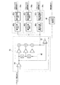
以下、図面を参照して本発明の一実施形態による機器管理システム及び機器管理プログラムについて詳細に説明する。図1は、本発明の一実施形態による機器管理システムの全体構成を示すブロック図である。図1に示す通り、本実施形態の機器管理システム1は、管理対象である機器10、モデム20(接続装置)、及び機器管理装置30を含んでなり、作業者(ユーザ)が機器管理装置30を操作して機器10の管理を行う。尚、機器10の管理とは、機器10の設定・調整や機器10で測定されたデータの収集をいう。
Hereinafter, a device management system and a device management program according to an embodiment of the present invention will be described in detail with reference to the drawings. FIG. 1 is a block diagram showing the overall configuration of a device management system according to an embodiment of the present invention. As shown in FIG. 1, the
機器10は、例えば温度、圧力、流量等の測定を行うフィールド機器である。この機器10は、プラントの内部に設置されて、プラント内に敷設されたフィールドバス等のバスBに接続される。尚、プラント内には複数の機器10が設置されてバスBに接続されるが、図1においては図示の簡単化のために、1つの機器10のみを図示している。
The
機器10には、ファンデーションフィールドバス(Foundation Fieldbus:登録商標)、HART(Highway Addressable Remote Transducer:登録商標)、プロフィバス(PROFIBUS:登録商標)、又はBRAIN等のプロセス工業用の汎用通信プロトコルがそれぞれ実装されている。機器10は、これらの通信プロトコルの何れか1つを用いて、バスBを介した通信、又はモデム20を介した通信を行う。
The
モデム20は、アナログフィルタ21、バッファ22、A/Dコンバータ23(第1変換部)、通信部24、及びD/Aコンバータ25(第2変換部)を備えており、バスBを介して機器10と機器管理装置30とを接続する。アナログフィルタ21は、バスBから入力される信号から、例えばサージ電流等を除去するフィルタである。バッファ22は、モデム20の入力回路の保護等を行うためのものである。尚、アナログフィルタ21及びバッファ22は、モデム20の故障を防止するために設けられるのが望ましいが、特に必要がなければ省略することが可能である。
The
A/Dコンバータ23は、バッファ22から出力される信号を所定のサンプリング周波数でサンプリングして、複数ビット(例えば、4ビット又は8ビット)からなるディジタルデータに変換する。ここで、A/Dコンバータ23のサンプリング周波数は、バスBを介して通信される信号の周波数の2倍以上の周波数である。
The A /
通信部24は、機器管理装置30との間の通信を実現するための通信インターフェイスであり、例えばUSB(Universal Serial Bus)、イーサネット(登録商標)、PCMCIA(Personal Computer Memory Card International Association)等で規定される通信インターフェイスを用いることができる。尚、図1においては、A/Dコンバータ23と通信部24とを分けて図示しているが、これらの機能を1つの集積回路で実現することも可能である。
The
D/Aコンバータ25は、通信部24から出力される機器管理装置30からの信号(ディジタル信号)をアナログ信号に変換してバスBを介して機器10に出力する。尚、機器管理装置30からの信号のビット数は、上記のA/Dコンバータ23と同様であり、例えば4ビット又は8ビットである。尚、一般的に「モデム」とは送信すべき信号を変調するとともに、受信した信号を復調するものをいうが、図1に示す通り、本実施形態の機器管理システム1で用いられるモデム20は、復調・変調を行う機能が設けられていないのが特徴である。
The D /
機器管理装置30は、通信部31、ドライバ部32、フィルタ部33(フィルタ手段)、プロトコル解析部34a〜34d(解析手段)、プロトコル選択部35(解析手段、選択手段)、及び管理部36(管理手段)を備えており、モデム20を介して機器10との間で通信を行って機器10の管理を行う。通信部31は、モデム20との間の通信を実現する通信インターフェイスであり、モデム20に設けられた通信部24と同様に、例えばUSB、イーサネット(登録商標)、PCMCIA等で規定される通信インターフェイスを用いることができる。
The
ドライバ部32は、通信部31を制御して、モデム20との間の通信経路を確立するとともに、モデム20との間で行われる通信の制御を行う。フィルタ部33は、ディジタルフィルタを備えており、ドライバ部32から出力される信号からノイズ成分を除去する。また、ドライバ部32から出力される信号に含まれる直流成分を負帰還させて、通信部31から出力される信号に対して直流成分の揺らぎを除去する。
The driver unit 32 controls the
図2は、機器管理装置30に設けられるフィルタ部33及びプロトコル解析部34a〜34dの内部構成を示すブロック図である。図2に示す通り、フィルタ部33は、帰還部41、ディジタルフィルタ部42、及び差分演算部43を備えており、ドライバ部32から出力される信号からノイズ成分及び直流成分の揺らぎを除去する。
FIG. 2 is a block diagram illustrating an internal configuration of the filter unit 33 and the
帰還部41は、ドライバ部32から出力される信号と差分演算部43から出力される信号とを入力としており、これらの差分を示す信号を出力する。ディジタルフィルタ部42は、帰還部41から出力される信号に対して所定のフィルタ処理を行ってノイズ成分を除去する。ここで、ディジタルフィルタ部42としては、有限インパルス応答(FIR:Finite Impulse Response)型のもの、及び無限インパルス応答(IIR:Infinite Impulse Response)型のものの何れをも用いることができる。差分演算部43は、帰還部41から出力される信号とディジタルフィルタ部42から出力される信号との差分を演算する。
The
プロトコル解析部34a〜34dは、フィルタ部33から出力される信号に対して、通信プロトコルの種類の応じた解析を行う。具体的には、プロトコル解析部34aはファンデーションフィールドバス(登録商標)に応じた解析を行い、プロトコル解析部34bはHART(登録商標)に応じた解析を行い、プロトコル解析部34cはプロフィバス(登録商標)に応じた解析を行う。尚、プロトコル解析部34dは以上の通信プロトコル以外の新たに規定された通信プロトコルに応じた解析を行うものであるとする。
The
ここで、図2に示す通り、プロトコル解析部34aは復号化部46a(復調手段)と解析処理部47a(解析処理手段)とを備えており、プロトコル解析部34bは復号化部46b(復調手段)と解析処理部47b(解析処理手段)とを備えている。また、プロトコル解析部34cは、復号化部46c(復調手段)と解析処理部47c(解析処理手段)とを備えている。尚、図2においては、プロトコル解析部34dの図示は省略している。
Here, as shown in FIG. 2, the
上記の復号化部46a,46b,46cは、フィルタ部33から出力される信号に対して、ファンデーションフィールドバス(登録商標)に応じた復調処理及び符号化、HART(登録商標)に応じた復調処理及び符号化、並びにプロフィバス(登録商標)に応じた復調処理及び符号化をそれぞれ行う。また、上記の解析処理部47a,47b,47cは、復号化部46a,46b,46cから出力される信号に対して、ファンデーションフィールドバス(登録商標)に応じた解析処理、HART(登録商標)に応じた解析処理、及びプロフィバス(登録商標)に応じた解析処理をそれぞれ行う。
The
ここで、上記の解析処理部47a,47b,47cの各々で行われる解析処理としては、例えば機器10から送信されるフレームを構成するヘッダやコマンドをチェックして、自身が解析する通信プロトコルに近いかを示す点数付けの処理(スコアリング処理)、及びフレームを構成するヘッダを除去してデータを抽出する処理等が挙げられる。これら解析処理部47a,47b,47cの処理結果は、プロトコル選択部35に出力される。尚、プロトコル解析部34a〜34dでは、機器10に対して送信すべきデータの変調も行われる。
Here, as an analysis process performed in each of the
プロトコル選択部35は、プロトコル解析部34a〜34dから出力されるスコアリング処理の処理結果のうち、点数(スコア)が最も高いものを機器10で用いられている通信プロトコルであると特定し、機器10との間の通信を行うために用いる通信プロトコルとして選択する。管理部36は、プロトコル選択部35で選択された通信プロトコルを用いてモデム20を介して機器10との間で通信を行い、機器10の管理を行う。
The protocol selection unit 35 identifies the scoring processing result output from the
また、図2に示す通り、機器管理装置30には、差分演算部43から出力される信号を入力としており、ドライバ部32から出力される信号に含まれるノイズを解析するノイズ解析部48(雑音分析手段)が設けられている。このノイズ解析部48は、具体的には、ドライバ部32から出力される信号に含まれるノイズのスペクトル分析や、バーストの検出を行う。このノイズ解析部48の解析結果は管理部36に入力されており、管理部36の管理下で保存されるとともに、ユーザの指示に基づいて保存された解析結果が読み出されて解析される。
As shown in FIG. 2, the
以上説明した機器管理装置30は、パーソナルコンピュータ等のコンピュータを用いて実現される。また、図1に示すドライバ部32、フィルタ部33、プロトコル解析部34a〜34d、プロトコル選択部35、及び管理部36、並びに、図2に示すノイズ解析部48は、それらの機能を実現すべく作成されたプログラムを実行又はロードすることによりソフトウェア的に実現される。
The
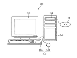
図3は、本発明の一実施形態による機器管理システムの一部をなす機器管理装置の外観を模式的に示す正面図であり、図4は同機器管理装置のハードウェア構成を示すブロック図である。図3に示す通り、機器管理装置30は、キーボード51a及びマウス51b等の入力装置51、CRT(Cathode Ray Tube)又は液晶表示装置等の表示装置52、及びドライブ装置53が設けられた装置本体部54を備える。尚、図3においては、入力装置51、表示装置52、及び装置本体部54が分離されたコンピュータで実現された機器管理装置30を図示しているが、機器管理装置30は入力装置51、表示装置52、及び装置本体部54が一体化された携帯性のあるコンピュータで実現されていていても良い。
FIG. 3 is a front view schematically showing the external appearance of a device management apparatus forming a part of the device management system according to the embodiment of the present invention, and FIG. 4 is a block diagram showing the hardware configuration of the device management apparatus. is there. As shown in FIG. 3, the
入力装置51は、機器管理装置30のユーザによって操作されて、ユーザの操作内容に応じた操作情報を装置本体部54に出力する。表示装置52は、機器管理装置30が管理している機器10の状態を示す情報等の装置本体部54から出力される各種情報を表示する。装置本体部54は、モデム20を介してバスBに接続されており、ユーザの指示に基づいて機器10の管理を行う。また、この装置本体部5は、インターネットにも接続可能である。
The
装置本体部54に設けられたドライブ装置53は、例えばCD−ROMドライブ又はDVD(登録商標)−ROMドライブ等である。このドライブ装置53は、CD−ROM又はDVD(登録商標)−ROM等のコンピュータ読み取り可能な記録媒体Mに記憶されているプログラムや各種データの読み取りを行う。
The
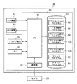
図4に示す通り、機器管理装置30の装置本体部54は、以上説明したドライブ装置53及び通信部31(図1参照)に加えて、CPU(中央処理装置)61、データ格納部62(保存装置)、及びメモリ63を備える。CPU61は、装置本体部54の動作を統括的に制御する。また、ユーザの指示に応じてデータ格納部62に格納された各種プログラムをロードすることにより、それらのプログラムの機能を実現する。
As shown in FIG. 4, in addition to the
データ格納部62は、機器管理装置30で実行される各種プログラムを格納するとともに、機器10から取得された各種データや図2に示すノイズ解析部48の解析結果を格納するものであり、例えばハードディスクで実現される。メモリ63は、CPU61の処理で用いられるデータを一時的に記憶するものであり、RAM(Random Access Memory)等の半導体メモリで実現することができる。
The
ここで、本実施形態では、上記の機器管理装置30で実行される各種プログラムとして、図4に示す各種プログラムがデータ格納部62に格納される。つまり、ドライバプログラムP1、フィルタプログラムP2、プロトコル解析プログラムP3a〜P3n、プロトコル選択プログラムP4、ノイズ解析プログラムP5、及びアプリケーションプログラムP6がデータ格納部62に格納される。
Here, in the present embodiment, various programs shown in FIG. 4 are stored in the
CPU61によってデータ格納部62からドライバプログラムP1がロードされることにより図1に示すドライバ部32が実現され、フィルタプログラムP2がロードされることにより図1又は図2に示すフィルタ部33が実現される。また、CPU61によってデータ格納部62からプロトコル解析プログラムP3a〜P3nがロードされることにより図1又は図2に示すプロトコル解析部34a〜34dが実現され、プロトコル選択プログラムP4がロードされることにより図1に示すプロトコル選択部35が実現される。
The driver unit 32 shown in FIG. 1 is realized by the
更に、CPU61によってデータ格納部62からノイズ解析プログラムP5がロードされることにより図2に示すノイズ解析部48が実現され、アプリケーションプログラムP6がロードされることにより図1に示す管理部36が実現される。アプリケーションプログラムP6はユーザの指示によって実行される実行可能形式のプログラムであるが、残りのプログラムは例えばアプリケーションプログラムP6に動的に関連付けられるライブラリとして提供されるプログラムである。ここで、通信プロトコルの解析を行う上記のプロトコル解析プログラムP3a〜P3nは個別に追加や削除が可能である。
Furthermore, the
上記のプログラムは、例えば図3に示す記録媒体Mに記録された状態で提供され、記録媒体Mに記録されたプログラムをドライブ装置53を用いて読み取ることにより装置本体部54のデータ格納部62に格納(インストール)される。また、上記のプログラムがインターネットを介して提供される場合には、装置本体部54をインターネットに接続し、インターネットを介して上記のプログラムをダウンロードしてインストールすることもできる。
The above program is provided, for example, in a state of being recorded on the recording medium M shown in FIG. 3, and the program recorded on the recording medium M is read using the
次に、上記構成における機器管理システム1の動作について説明する。ユーザからの指示があると、図4に示すCPU61によってデータ格納部62からアプリケーションプログラムP6がロードされて実行される。アプリケーションプログラムP6が実行されると、データ格納部62からドライバプログラムP1、フィルタプログラムP2、プロトコル解析プログラムP3a〜P3n、プロトコル選択プログラムP4、及びノイズ解析プログラムP5が併せてロードされる。これにより、図1に示すドライバ部32、フィルタ部33、プロトコル解析部34a〜34d、プロトコル選択部35、及び管理部36、並びに図2に示すノイズ解析部48が実現される。
Next, the operation of the
尚、ここでは、アプリケーションプログラムP6が実行された場合に、ドライバプログラムP1〜ノイズ解析プログラムP5が併せてロードされる場合を例に挙げて説明するが、ドライバプログラムP1〜ノイズ解析プログラムP5は、機器管理装置30の電源が投入された時点でCPU61にロードされて実行されても良い。以上の処理が終了すると、機器管理装置30が機器10を管理できる状態になる。
Here, a case where the driver program P1 to the noise analysis program P5 are loaded together when the application program P6 is executed will be described as an example. However, the driver program P1 to the noise analysis program P5 are It may be loaded into the
機器10から出力された信号は、バスBを介してモデム20に入力され、アナログフィルタ21及びバッファ22を介してA/Dコンバータ23に入力されてサンプリングされる。これにより機器10から出力された信号はディジタル信号に変換される。A/Dコンバータ23で変換されたディジタル信号は通信部24によって機器管理装置30に送信される。即ち、機器10から出力された信号をサンプリングしただけの生のディジタル信号(復調処理や符号化が行われていないディジタル信号)がモデム20から機器管理装置30に送信される。
The signal output from the
モデム20から機器管理装置30に送信されたディジタル信号は、機器管理装置30の通信部31で受信され、ドライバ部32を介してフィルタ部33に入力され、図2に示すディジタルフィルタ部42によってノイズ成分が除去される。また、図2に示す帰還部41から出力される信号とディジタルフィルタ部42から出力される信号との差分が差分演算部43で演算されるとともに、この差分演算部43から出力される信号とドライバ部32から出力される信号との差分が帰還部41で求められることにより、ドライバ部32から出力される信号の直流成分の揺らぎが除去される。
A digital signal transmitted from the
フィルタ部33においてノイズ成分や直流成分の揺らぎが除去された信号はプロトコル解析部34a〜34dに入力され、プロトコル解析部34a〜34dの各々において通信プロトコルの種類の応じた解析が行われる。具体的には、例えば図2に示す通り、復号化部46a〜46cにおいて、ファンデーションフィールドバス(登録商標)に応じた復調処理及び符号化、HART(登録商標)に応じた復調処理及び符号化、並びにプロフィバス(登録商標)に応じた復調処理及び符号化がそれぞれ行われる。
The signal from which the noise component and the DC component fluctuation have been removed in the filter unit 33 is input to the
そして、復号化部46a〜46cで得られた復調信号に対し、解析処理部47a,47b,47cの各々で、ファンデーションフィールドバス(登録商標)、HART(登録商標)、及びプロフィバス(登録商標)に応じたスコアリング処理が行われる。解析処理部47a,47b,47cで行われたスコアリング処理の処理結果はプロトコル選択部35に出力され、点数(スコア)が最も高いものが機器10との間の通信を行うために用いる通信プロトコルとして選択される。例えば、解析処理部47aから出力された処理結果の点数が、他の解析処理部47b,47cから出力された処理結果の点数よりも高ければファンデーションフィールドバス(登録商標)が通信プロトコルとして選択される。
Then, with respect to the demodulated signals obtained by the
以上の処理が終了すると、プロトコル選択部35で選択された通信プロトコルを用いて、管理部36と機器10との間でモデム20を介した通信が可能になり、ユーザの指示に応じた機器管理装置30による機器10の管理が実施される。例えば、ユーザによって温度、圧力、流量等の測定結果を機器10から収集すべき旨の指示がなされた場合には、機器10の測定結果を収集すべき旨の制御信号が管理部36から出力される。
When the above processing ends, communication using the communication protocol selected by the protocol selection unit 35 can be performed between the
この制御信号は、プロトコル選択部35で選択された通信プロトコルに応じて変調される。例えば、ファンデーションフィールドバス(登録商標)が選択されている場合には、そのファンデーションフィールドバス(登録商標)に応じた変調がなされる。変調された制御信号は、フィルタ部33及びドライバ32を順に介した後に、通信部31によってモデム20に向けて送信される。モデム20に向けて送信された制御信号は通信部24で受信された後に、D/Aコンバータ25でアナログ信号に変換された後に、バスBを介して機器10に受信される。
This control signal is modulated according to the communication protocol selected by the protocol selection unit 35. For example, when Foundation Fieldbus (registered trademark) is selected, modulation according to the Foundation Fieldbus (registered trademark) is performed. The modulated control signal is transmitted to the
機器管理装置30からの制御信号を受信すると、この制御信号に対する応答として温度、圧力、流量等の測定結果を示す信号が機器10から機器管理装置30に向けて送信される。機器10から出力された信号は、先の説明と同様に、モデム20のA/Dコンバータ23に入力されてサンプリングされてディジタル信号に変換された後に、通信部24によって機器管理装置30に送信される。
When a control signal from the
モデム20から機器管理装置30に送信されたディジタル信号は、機器管理装置30の通信部31で受信され、ドライバ部32及びフィルタ部33を順に介してプロトコル解析部34a〜34dに入力される。そして、プロトコル解析部34a〜34dのうちのプロトコル選択部35で選択された通信プロトコルを扱うプロトコル解析部で、その通信プロトコルに応じた解析が行われる。
The digital signal transmitted from the
具体的には、プロトコル選択部35で選択された通信プロトコルに応じた復調処理及び符号化が行われ、その後にフレームを構成するヘッダを除去してデータを抽出する処理等が行われる。抽出されたデータは、プロトコル選択部35を介して管理部36に入力される。以下、同様の処理が繰り返されて機器10の測定結果が機器管理装置30の管理部36に収集される。尚、管理部36に収集された測定結果は、図4に示すデータ格納部62に保存される。
Specifically, demodulation processing and encoding are performed in accordance with the communication protocol selected by the protocol selection unit 35, and thereafter processing for removing the header constituting the frame and extracting data is performed. The extracted data is input to the
また、ユーザの指示によって、図2に示すノイズ解析部48の解析結果も管理部36に収集することができる。管理部36に収集されたノイズ解析部48の解析結果は、上記の測定結果と同様に、図4に示すデータ格納部62に保存される。データ格納部62に保存された測定結果及びノイズの解析結果は、ユーザの指示に応じて読み出されて解析される。
Further, the analysis result of the
以上説明した通り、本実施形態では、機器10から出力される信号をサンプリングして機器管理装置30に出力するA/Dコンバータ23と機器管理装置30からの制御信号をアナログ信号に変換して機器に出力するD/Aコンバータ25とを備えるモデム20を用いて機器10と機器管理装置30とを接続している。そして、モデム20でサンプリングされた信号を機器管理装置30で解析して機器10で用いている通信プロトコルを特定し、この特定された通信プロトコルを用いて機器10との間で通信を行って機器10の管理を行っている。ここで、機器管理装置30で通信プロトコルの解析のために用いられるプログラムは、通信プロトコルの種類毎に追加、削除を行うことができる。
As described above, in the present embodiment, the A /
このため、以下の(1)〜(6)に示す効果が得られる。
(1)複数種類のバスが混在する場合であっても、そのバスの種類の分だけモデムを用意する必要がなく、1つのモデムで対応することができるため、ユーザの投資、及び管理や操作に要する負担を軽減することができる。
(2)バスの仕様が変更された場合には、機器管理装置30のプログラム(プロトコル解析プログラム)の変更で対応することができ、従来のようにモデムの交換又はモデム内に存在するファームウェアの更新等のメンテナンス作業を行う必要がないため、ユーザに強いられていた繁雑な作業の負担を軽減することができる。
(3)新しい種類のバスが追加された場合であっても、そのバスに対応可能なモデムを購入する必要はなく、機器管理装置30のプログラム(プロトコル解析プログラム)の追加で対応することができる。
For this reason, the effect shown to the following (1)-(6) is acquired.
(1) Even when a plurality of types of buses coexist, it is not necessary to prepare modems corresponding to the types of buses, and a single modem can be used. Therefore, user investment, management, and operation are possible. Can be reduced.
(2) When the bus specification is changed, it can be dealt with by changing the program (protocol analysis program) of the
(3) Even when a new type of bus is added, it is not necessary to purchase a modem that can support the bus, and it can be handled by adding a program (protocol analysis program) of the
(4)バスを介した通信が正常に行われない場合には、バスの通信状況を診断するプログラムを機器管理装置30にインストールしさえすれば診断することができるため、従来のようにバスの通信状況を診断する特殊な診断装置を別途用意する必要はない。
(5)従来に比べてモデム20の構成を単純化できるため、防爆仕様に対応し易くなるとともに、バッテリの超寿命化、寸法の低減(小型化)、低コスト化を実現することができる。
(6)信号線のノイズ等の全履歴を機器管理装置30で保存することができるため、プラントで何らかの障害が生じた場合の診断を容易に行うことができる。
(4) If communication via the bus is not normally performed, it can be diagnosed only by installing a program for diagnosing the bus communication status in the
(5) Since the configuration of the
(6) Since the entire history of signal line noise and the like can be stored in the
以上、本発明の一実施形態による機器管理システム及び機器管理プログラムについて説明したが、本発明は上述した実施形態に制限されることなく、本発明の範囲内で自由に変更が可能である。例えば、上記実施形態では、機器管理装置30がパーソナルコンピュータ等のコンピュータにより実現される例について説明した。しかしながら、本発明はパーソナルコンピュータ以外に、PDA(Personal Digital Assistant:携帯情報端末)や携帯電話機等を用いて機器管理装置30を実現することもできる。
Although the device management system and the device management program according to the embodiment of the present invention have been described above, the present invention is not limited to the above-described embodiment, and can be freely changed within the scope of the present invention. For example, in the above embodiment, the example in which the
また、以上説明した実施形態では、図4に示すCPU61がデータ格納部62に格納された各種プログラムをロードすることにより図1に示すドライバ部32〜管理部36がソフトウェア的に実現される場合を例に挙げて説明した。しかしながら、これらをハードウェア的に実現することも可能である。但し、ハードウェア的に実現した場合には、図1に示すプロトコル解析部34a〜34dの追加、削除等が困難になるため、ソフトウェア的に実現するのが望ましい。
In the embodiment described above, the
1 機器管理システム
10 機器
20 モデム
23 A/Dコンバータ
25 D/Aコンバータ
30 機器管理装置
33 フィルタ部
34a〜34d プロトコル解析部
35 プロトコル選択部
36 管理部
46a〜46c 復号化部
47a〜47c 解析処理部
48 ノイズ解析部
62 データ格納部
DESCRIPTION OF
Claims (6)
前記接続装置は、前記シリアルバスを介して入力される前記機器からの信号を該信号の周波数の2倍以上のサンプリング周波数でサンプリングして前記機器管理装置に出力する第1変換部と、前記機器管理装置から出力される信号をアナログ信号に変換して前記シリアルバスを介して前記機器に出力する第2変換部とを備えており、
前記機器管理装置は、前記接続装置から出力される信号を解析して前記機器で使用されている通信プロトコルを特定する解析手段と、該解析手段で特定された通信プロトコルを用いて前記接続装置を介して前記機器との間で通信を行って前記機器の管理を行う管理手段とを備える
ことを特徴とする機器管理システム。 And managed devices connected to the serial bus, a device management apparatus for managing the equipment, the equipment management system comprising a connection device which connects the device management apparatus and the device via the serial bus,
The connecting device samples a signal from the device input via the serial bus at a sampling frequency that is twice or more the frequency of the signal, and outputs the sample to the device management device; and the device A second converter that converts a signal output from the management device into an analog signal and outputs the analog signal to the device via the serial bus ;
The device management apparatus, the analysis unit analyzes the signal output from the connection device identifies a communication protocol used by the device, the connecting device using the communication protocol identified in the analysis means And a management unit that manages the device by communicating with the device via the device management system.
前記複数の復調手段に対応してそれぞれ設けられ、対応する復調手段で得られた復調信号に対して前記通信プロトコルの種類に応じた解析処理を行う複数の解析処理手段と、
前記解析処理手段の処理結果に基づいて前記通信プロトコルを選択する選択手段と
を備えることを特徴とする請求項1記載の機器管理システム。 The analysis means is provided for each type of the communication protocol, and a plurality of demodulation means for performing demodulation processing according to the type of the communication protocol with respect to a signal output from the connection device,
A plurality of analysis processing means provided corresponding to the plurality of demodulation means, respectively, and performing analysis processing according to the type of the communication protocol on the demodulated signal obtained by the corresponding demodulation means;
The device management system according to claim 1, further comprising: a selection unit that selects the communication protocol based on a processing result of the analysis processing unit.
前記雑音分析手段の分析結果を保存する保存装置と
を備えることを特徴とする請求項1から請求項3の何れか一項に記載の機器管理システム。 The device management apparatus, a noise analysis means for analyzing noise included in a signal output from the connection device,
The apparatus management system according to claim 1, further comprising: a storage device that stores an analysis result of the noise analysis unit.
シリアルバスに接続された管理対象の機器から出力されて前記シリアルバスを介して通信される信号の周波数の2倍以上のサンプリング周波数でサンプリングされた信号を解析して前記機器で使用されている通信プロトコルを特定する解析手段と、
前記解析手段で特定された通信プロトコルを用いて前記機器との間で通信を行って前記機器の管理を行う管理手段と
して機能させることを特徴とする機器管理プログラム。 Computer
Communication used by the device by analyzing a signal output from a managed device connected to the serial bus and sampled at a sampling frequency that is twice or more the frequency of the signal communicated via the serial bus Analysis means to identify the protocol;
A device management program that functions as a management unit that manages the device by communicating with the device using the communication protocol specified by the analysis unit.
前記複数の復調手段に対応してそれぞれ設けられ、対応する復調手段で得られた復調信号に対して前記通信プロトコルの種類に応じた解析処理を行う複数の解析処理手段と、
前記解析処理手段の処理結果に基づいて前記通信プロトコルを選択する選択手段と
を含むことを特徴とする請求項5記載の機器管理プログラム。 The analysis means is provided for each type of communication protocol, and a plurality of demodulation means for performing demodulation processing according to the type of communication protocol for the sampled signal,
A plurality of analysis processing means provided corresponding to the plurality of demodulation means, respectively, and performing analysis processing according to the type of the communication protocol on the demodulated signal obtained by the corresponding demodulation means;
6. A device management program according to claim 5, further comprising selection means for selecting the communication protocol based on a processing result of the analysis processing means.
Priority Applications (1)
| Application Number | Priority Date | Filing Date | Title |
|---|---|---|---|
| JP2008332772A JP5293174B2 (en) | 2008-12-26 | 2008-12-26 | Device management system and device management program |
Applications Claiming Priority (1)
| Application Number | Priority Date | Filing Date | Title |
|---|---|---|---|
| JP2008332772A JP5293174B2 (en) | 2008-12-26 | 2008-12-26 | Device management system and device management program |
Publications (2)
| Publication Number | Publication Date |
|---|---|
| JP2010152826A JP2010152826A (en) | 2010-07-08 |
| JP5293174B2 true JP5293174B2 (en) | 2013-09-18 |
Family
ID=42571805
Family Applications (1)
| Application Number | Title | Priority Date | Filing Date |
|---|---|---|---|
| JP2008332772A Expired - Fee Related JP5293174B2 (en) | 2008-12-26 | 2008-12-26 | Device management system and device management program |
Country Status (1)
| Country | Link |
|---|---|
| JP (1) | JP5293174B2 (en) |
Families Citing this family (2)
| Publication number | Priority date | Publication date | Assignee | Title |
|---|---|---|---|---|
| CN103391284B (en) * | 2012-05-07 | 2019-01-01 | 布里斯托尔D/B/A远程自动化解决方案公司 | The method and apparatus of communication protocol currently in use in identification process control system |
| CN112383619B (en) * | 2020-11-13 | 2024-05-17 | 广联达科技股份有限公司 | Data transmission method, system and electronic equipment |
Family Cites Families (4)
| Publication number | Priority date | Publication date | Assignee | Title |
|---|---|---|---|---|
| JP2003069731A (en) * | 2001-08-29 | 2003-03-07 | Mitsubishi Electric Corp | Equipment status remote monitoring system |
| JP2004120668A (en) * | 2002-09-30 | 2004-04-15 | Yokogawa Electric Corp | Signal transmitter compatible with multiple communication protocols |
| CN100507781C (en) * | 2004-03-02 | 2009-07-01 | 罗斯蒙德公司 | Field-mounted process device with programmable digital/analog interface |
| JP2008271370A (en) * | 2007-04-24 | 2008-11-06 | Matsushita Electric Ind Co Ltd | A / D conversion system |
-
2008
- 2008-12-26 JP JP2008332772A patent/JP5293174B2/en not_active Expired - Fee Related
Also Published As
| Publication number | Publication date |
|---|---|
| JP2010152826A (en) | 2010-07-08 |
Similar Documents
| Publication | Publication Date | Title |
|---|---|---|
| US8910143B2 (en) | Conversion system and method for use in upgrading a monitoring system | |
| US8868971B2 (en) | Wireless diagnostic system | |
| CN106201757B (en) | Exception handling method and device | |
| JP5104673B2 (en) | Device management apparatus and program | |
| CN101291509A (en) | Mobile terminal device, diagnostic method of mobile terminal device | |
| JPH10228311A (en) | Remote diagnosis system for equipment failure | |
| US7689373B1 (en) | USB vibration data acquisition | |
| JP5293174B2 (en) | Device management system and device management program | |
| JP2016114341A (en) | Data collection device, data collection system, control method and program | |
| CN111108453B (en) | Control system, control method and control program | |
| JP5178774B2 (en) | Air conditioning communication information collection device, air conditioning communication information collection system, air conditioning communication information collection method and program | |
| CN115098554A (en) | Vehicle automatic driving data processing method and device, electronic equipment and storage medium | |
| US20070168729A1 (en) | System and method for testing and debugging electronic apparatus in single connection port | |
| CN112214463B (en) | GPS terminal monitoring method, device, system and storage medium | |
| CN111239523B (en) | Frequency converter testing system, method and device and storage medium | |
| JP2004240513A (en) | Production facility status analysis device | |
| EP1926206A1 (en) | Frequency converter | |
| CN113484710A (en) | Graphical user interface for traffic capture and debugging tool | |
| CN116736750B (en) | Turbine generator rotor rotating speed signal simulation system of measurement and control instrument while drilling | |
| JP2005275713A (en) | Maintenance information management system | |
| CN213928709U (en) | Pump equipment's fault monitoring system and pump equipment based on high in clouds | |
| EP3448054A1 (en) | Remote monitoring system, central data collection device, field data collection device, remote monitoring method, and program | |
| CN120405254A (en) | Intelligent comprehensive maintenance and testing system and method based on multiple frequency converters | |
| CN209946283U (en) | Relay protection tester | |
| CN118555596A (en) | A radio-based information signal analyzer system |
Legal Events
| Date | Code | Title | Description |
|---|---|---|---|
| A621 | Written request for application examination |
Free format text: JAPANESE INTERMEDIATE CODE: A621 Effective date: 20110825 |
|
| A977 | Report on retrieval |
Free format text: JAPANESE INTERMEDIATE CODE: A971007 Effective date: 20121205 |
|
| A131 | Notification of reasons for refusal |
Free format text: JAPANESE INTERMEDIATE CODE: A131 Effective date: 20130115 |
|
| A521 | Request for written amendment filed |
Free format text: JAPANESE INTERMEDIATE CODE: A523 Effective date: 20130215 |
|
| TRDD | Decision of grant or rejection written | ||
| A01 | Written decision to grant a patent or to grant a registration (utility model) |
Free format text: JAPANESE INTERMEDIATE CODE: A01 Effective date: 20130514 |
|
| A61 | First payment of annual fees (during grant procedure) |
Free format text: JAPANESE INTERMEDIATE CODE: A61 Effective date: 20130527 |
|
| R150 | Certificate of patent or registration of utility model |
Ref document number: 5293174 Country of ref document: JP Free format text: JAPANESE INTERMEDIATE CODE: R150 Free format text: JAPANESE INTERMEDIATE CODE: R150 |
|
| LAPS | Cancellation because of no payment of annual fees |