JP5290613B2 - Inkjet recording device - Google Patents
Inkjet recording device Download PDFInfo
- Publication number
- JP5290613B2 JP5290613B2 JP2008111904A JP2008111904A JP5290613B2 JP 5290613 B2 JP5290613 B2 JP 5290613B2 JP 2008111904 A JP2008111904 A JP 2008111904A JP 2008111904 A JP2008111904 A JP 2008111904A JP 5290613 B2 JP5290613 B2 JP 5290613B2
- Authority
- JP
- Japan
- Prior art keywords
- ink
- recording
- cap
- recording medium
- recording head
- Prior art date
- Legal status (The legal status is an assumption and is not a legal conclusion. Google has not performed a legal analysis and makes no representation as to the accuracy of the status listed.)
- Expired - Fee Related
Links
Images


Abstract
Description
本発明は、インク滴を吐出させて画像を記録するインクジェット記録装置およびその予備吐出方法に関し、特に記録ヘッドと記録ヘッドをキャップする手段を備えるインクジェット記録装置に関する。 The present invention is, by ejecting ink droplets relates to an inkjet recording apparatus and method preliminary ejection for recording an image relates to an ink jet recording apparatus comprising means for capping the recording head and the recording head in particular.
インクジェット記録方式には、静電吸引方式、圧電素子を用いてインクを吐出する方式、インクを加熱してインクが発泡する圧力を利用する方式等、種々のインク吐出方法がある。これらの方式により、記録ヘッドからインクの微小液滴を飛翔させて記録媒体に記録を行う。これらのインクジェット記録方式は、記録時の騒音発生が少なく、またインクのノズルを高密度に集積した記録ヘッドを使用することにより、高解像度かつ高速で記録することが可能である。 Inkjet recording methods include various ink ejection methods such as an electrostatic suction method, a method of ejecting ink using a piezoelectric element, and a method of using a pressure at which ink is heated to boil the ink. By these methods, recording is performed on a recording medium by ejecting micro droplets of ink from the recording head. These ink jet recording methods generate less noise during recording, and can record at high resolution and high speed by using a recording head in which ink nozzles are densely integrated.
しかしながら、インクジェット記録装置は、液体のインクを微小なノズルから吐出して記録するという機構上、非動作時においてノズル内のインクの水分が蒸発することによるインクの粘度上昇、インク中の色材などの凝集をもたらす場合がある。これにより、動作再開時において記録ヘッドの吐出性能が低下(インクの吐出方向や吐出速度の不安定化、インクの不吐出など)する場合がある。 However, the ink jet recording apparatus has a mechanism in which liquid ink is ejected from a minute nozzle for recording, the ink viscosity increases due to evaporation of ink water in the nozzle during non-operation, the coloring material in the ink, etc. May cause aggregation. As a result, when the operation is resumed, the ejection performance of the recording head may deteriorate (unstable ink ejection direction or ejection speed, non-ejection of ink, etc.).
このため、従来のインクジェット記録装置は、記録媒体への記録に先立って、水分が蒸発し増粘したノズル内のインクを予備吐出または吸引回復することにより、記録ヘッドの吐出性能の低下を防止している。 Therefore, prior to recording on a recording medium, a conventional inkjet recording apparatus prevents a decrease in ejection performance of the recording head by preliminarily ejecting or recovering the ink in the nozzles whose water has evaporated and thickened. ing.
さらに、非動作時間が長期にわたる場合に記録ヘッド表面のノズル周辺部やノズル内のインクが乾燥により固着して吐出不良が生じることやごみ等が付着することを防止するため、記録ヘッド表面を外部から覆い保護するキャップを一般的に備えている。このキャップは通常ゴム等の材質で構成されており、キャップ自身がある程度の水分を透過させてしまう。また、圧力変動によるインクの逆流を防止するために、記録ヘッド表面を外部から密封しないように大気と連通した構成となっている。そのため、キャッピング状態であっても非動作時間が長期にわたる場合にはノズル内のインクは徐々に水分が蒸発してしまい、次回記録動作時には予備吐出動作または吸引回復動作が必要となる場合が多い。 Furthermore, when the non-operating time is long, the print head surface is externally attached to prevent the ink around the nozzles on the print head surface and the ink in the nozzles from adhering due to drying, resulting in poor discharge or dust. It is generally equipped with a cap that covers and protects it. This cap is usually made of a material such as rubber, and the cap itself permeates a certain amount of moisture. Further, in order to prevent the back flow of ink due to pressure fluctuation, the recording head surface is communicated with the atmosphere so as not to be sealed from the outside. For this reason, when the non-operation time is long even in the capping state, the ink in the nozzles gradually evaporates, and a preliminary ejection operation or a suction recovery operation is often required during the next recording operation.
一方、近年、インクジェット記録装置には、色域の拡大、階調性の向上、粒状性の低下などを図るため、インクの多色化やノズルの微細化が行われている。これは、インクの水分蒸発の観点からは好ましくない。なぜなら、各色インクを設計するに際し、各色インクの水のモル分率を同一にするのは困難であり、各色インクの水のモル分率にはばらつきがある。そのため、キャップ内で各色インクが水分の蒸発または吸湿を生じる。このことは、相対的に乾燥が進みやすいインクとそうでないインクとを存在させてしまう。また、ノズルが微細化するほどインクの水分蒸発による吐出不良が起きやすいため、頻繁に予備吐出動作や吸引回復動作が必要となってしまう。 On the other hand, in recent years, in order to increase the color gamut, improve the gradation, and decrease the graininess of the ink jet recording apparatus, the number of inks is increased and the nozzles are made finer. This is not preferable from the viewpoint of water evaporation of the ink. This is because, in designing each color ink, it is difficult to make the water water mole fraction of each color ink the same, and the water water mole fraction of each color ink varies. Therefore, each color ink causes evaporation or moisture absorption in the cap. This causes ink that is relatively easy to dry and ink that does not. Also, as the nozzles become finer, ejection failure due to ink moisture evaporation tends to occur, so frequent preliminary ejection operations and suction recovery operations are required.
予備吐出動作や吸引回復動作は、インクを吐出または吸引させるため、これらの動作が頻繁に行われるほどインクタンク内のインクの消費量は多くなる。このため、記録に用いるためのインク量が減少し、ランニングコストが増大してしまう。 Since the preliminary ejection operation and the suction recovery operation cause ink to be ejected or sucked, the amount of ink consumed in the ink tank increases as these operations are performed more frequently. For this reason, the amount of ink used for recording decreases, and the running cost increases.
また、インクジェット記録装置本体に収容できるインク量(廃インク量)は有限であるため、高い頻度で予備吐出や吸引回復を行う構成とすると、廃インクを回収するスペースを大きくしなければならない、或いは製品寿命を縮めてしまうことにもなる。 Further, since the amount of ink (waste ink amount) that can be accommodated in the ink jet recording apparatus main body is finite, if it is configured to perform preliminary ejection or suction recovery at a high frequency, the space for collecting waste ink must be increased, or It will also shorten the product life.
このように、従来のインクジェット記録装置では、予備吐出や吸引回復などを行い、記録ヘッドの吐出性能を防止することが汎用的に行われている。しかし、ランニングコストを抑えるためにはインクを排出する頻度を少なくして廃インク量を低減する必要がある。例えば、非動作時間に基づいて回復動作の種類(予備吐出動作または吸引回復動作)を選択することや、あるいは各回復動作でのインクの吐出量または吸引量についての条件を選択することにより、廃インク量を低減する制御が行われている。 As described above, in the conventional ink jet recording apparatus, predischarge and suction recovery are generally performed to prevent the discharge performance of the recording head. However, in order to reduce the running cost, it is necessary to reduce the amount of waste ink by reducing the frequency of ink discharge. For example, by selecting the type of recovery operation (preliminary ejection operation or suction recovery operation) based on the non-operation time, or by selecting the conditions for the ink ejection amount or suction amount in each recovery operation, Control is performed to reduce the ink amount.
吸引回復動作は予備吐出動作に比べて多くのインクを排出するため、吸引回復動作を行う頻度を減らして予備吐出動作により記録ヘッドを回復させることが望ましい。そのためには、非動作時、つまりキャッピング時におけるインク中の水分蒸発をできるだけ低減することが有効である。前述のように、キャッピング状態であっても非動作時間が長期にわたる場合にはノズル内のインク中の水分は徐々に蒸発してしまう。しかし、このような状況を想定して、キャッピング時にキャップ内に予備吐出を行いインクでキャップ内を湿潤させ、キャップ内を高湿にしておくことで、非動作時におけるインク中の水分蒸発を低減するインクジェット記録装置が開示されている(特許文献1)。
しかしながら、特許文献1のインクジェット記録装置は、非動作時にキャップ内にインクを吐出してキャッピングを行うものの、吐出するインクを選択する構成ではない。このため、水のモル分率が低いインクを吐出する場合もあり、キャップ内を十分に高湿に保てず、非動作時間が長期にわたる場合においてノズル内のインクの乾燥を十分に抑えることができない場合がある。その結果、次回の動作時において回復動作が必要となり、廃インク量が増大してしまう場合があった。
However, although the ink jet recording apparatus of
そこで、本発明は、上述の課題を解決するためになされたもので、キャッピングされた状態においてノズル内のインクの水分蒸発を好適に抑制するインクジェット記録装置を提供することを目的としている。 SUMMARY An advantage of some aspects of the invention is that it provides an ink jet recording apparatus that suitably suppresses water evaporation of ink in a nozzle in a capped state.
上記課題を解決するための本発明は、少なくともブラックインク、イエローインク、マゼンタインク、及びシアンインクを吐出する記録ヘッドと、該記録ヘッドのノズル形成面をキャッピングするキャップと、前記記録ヘッドに前記キャップ内に前記イエローインクを予備吐出させ、前記キャップ内に前記イエローインクがある状態で前記キャップを前記ノズル形成面にキャッピングする制御手段とを備えるインクジェット記録装置において、
前記制御手段は、前記イエローインクの残量が所定量未満で、かつ前記マゼンタインクの残量が所定量以上の場合は、前記記録ヘッドに前記マゼンタインクを予備吐出させ、前記イエローインク及び前記マゼンタインクの残量が所定量未満で、かつ前記シアンインクの残量が所定量以上の場合は、前記記録ヘッドに前記シアンインクを予備吐出させ、前記イエローインク、前記マゼンタインク、及び前記シアンインクの残量が所定量未満の場合は、前記記録ヘッドにいずれのインクも予備吐出させないことを特徴とする。
In order to solve the above-described problems, the present invention provides a recording head that discharges at least black ink, yellow ink, magenta ink, and cyan ink, a cap that caps the nozzle formation surface of the recording head, and the cap on the recording head. In the ink jet recording apparatus comprising: a controller for pre-discharging the yellow ink in the cap, and capping the cap on the nozzle forming surface in a state where the yellow ink is in the cap.
When the remaining amount of the yellow ink is less than a predetermined amount and the remaining amount of the magenta ink is equal to or larger than the predetermined amount, the control unit causes the recording head to pre-discharge the magenta ink, and the yellow ink and the magenta ink When the remaining amount of ink is less than a predetermined amount and the remaining amount of cyan ink is greater than or equal to a predetermined amount, the recording head is preliminarily ejected with the cyan ink, and the yellow ink, the magenta ink, and the cyan ink are remaining If there is less than a predetermined amount, it characterized that it will not cause any ink also preliminary discharged to the recording head.
本発明によれば、キャッピングされた状態においてノズル内のインクの水分蒸発を好適に抑制し、廃インク量を低減することができる。 According to the present invention, it is possible to suitably suppress water evaporation of the ink in the nozzle in the capped state, and to reduce the amount of waste ink.
インクは通常、水などの湿潤成分と、溶剤、保湿剤などの保湿成分とを含んでおり、このようなインクは水の蒸気圧降下が起こっている。水の蒸気圧降下はモル分率によって決まり、インク中の水の蒸気圧、つまり水蒸気分圧は、下記(1)で算出することができる。
(1):インク中の水蒸気分圧=その温度での飽和水蒸気圧×インク中の水分モル分率(%)
一方、湿度とは一般的に相対湿度(%)のことを指し、ある温度での大気中に含まれる水蒸気分圧を、その温度の飽和水蒸気圧で割ったものである。別の表現をすると下記(2)のように表すことができる。
(2):大気中の水蒸気分圧=その温度での飽和水蒸気圧×相対湿度(%)
インクは、インク中の水蒸気分圧とその温度及び湿度における水蒸気分圧との差を埋めるように蒸発または吸湿して平衡状態になろうとし、その蒸発速度および吸湿速度は上記(1)、(2)式の差となる。つまり、下記(3)に比例することが知られている。
(3):インク中の水分モル分率(%)−相対湿度(%)
インク中の水のモル分率が相対湿度よりも高い場合には、インク中の水分が蒸発し、インク中の水分モル分率が相対湿度よりも低い場合には、インク中の水分は大気中より水分を吸湿して(3)式が0になるよう進行して平衡に達する。
Ink usually contains a moistening component such as water and a moisturizing component such as a solvent and a humectant, and such an ink causes a drop in the vapor pressure of water. The water vapor pressure drop is determined by the molar fraction, and the water vapor pressure in the ink, that is, the water vapor partial pressure, can be calculated by the following (1).
(1): Water vapor partial pressure in ink = saturated water vapor pressure at that temperature × moisture mole fraction in ink (%)
On the other hand, humidity generally refers to relative humidity (%), which is the partial pressure of water vapor contained in the atmosphere at a certain temperature divided by the saturated water vapor pressure at that temperature. In other words, it can be expressed as (2) below.
(2): Water vapor partial pressure in the atmosphere = saturated water vapor pressure at that temperature × relative humidity (%)
The ink tends to be in an equilibrium state by evaporating or absorbing moisture so as to fill the difference between the partial pressure of water vapor in the ink and the partial pressure of water vapor at the temperature and humidity, and the evaporation rate and moisture absorption rate are the above (1), ( 2) The difference between the equations. That is, it is known that it is proportional to the following (3).
(3): Moisture mole fraction in ink (%)-relative humidity (%)
When the mole fraction of water in the ink is higher than the relative humidity, the moisture in the ink evaporates, and when the moisture mole fraction in the ink is lower than the relative humidity, the moisture in the ink Moisture is absorbed more so that the equation (3) proceeds to zero and reaches equilibrium.
上記のことから、キャップ内を高湿度にするためには、各インクの平均より高く、できるだけ相対的に水のモル分率の高い(湿潤成分を多量に含む)インクをキャップ内に滞留させることが重要である。一般に、インク中の水以外の成分は水と比較して分子量が大きい。このため、異なるインクにおいて水のモル分率がわずか数%異なるだけであっても、両者のインクに含まれる重量換算での水の量は大きく異なる。このことは、キャップ内の初期湿度がわずかに異なるだけで、ノズル内のインクからの水分蒸発は大きく異なることを意味し、水のモル分率の高いインクでキャップ内を湿潤させることが、ノズル内のインクの水分蒸発の低減に有効であることを示している。 From the above, in order to make the inside of the cap high in humidity, it is necessary to retain ink in the cap that is higher than the average of each ink and has a relatively high molar fraction of water (containing a large amount of wet components) as much as possible. is important. In general, components other than water in the ink have a higher molecular weight than water. For this reason, even if the molar fractions of water differ by only a few percent in different inks, the amount of water in terms of weight contained in both inks differs greatly. This means that the initial humidity in the cap is slightly different, and the water evaporation from the ink in the nozzle is greatly different. It is effective for reducing the water evaporation of the ink inside.
本発明のインクジェット記録装置およびその吐出性能低下防止方法は、キャップ内を湿潤させた状態で記録ヘッドのノズル形成面を鉛直方向に下方からキャッピングする。このキャップ内を湿潤させるためにキャップ内に吐出するインクは、当該記録装置が備えるインクのうち揮発性の湿潤成分を多く含むインクである。こうして、キャップ内に吐出したインクによってキャップ内を好適に湿潤させ、揮発性の湿潤成分を多くキャップ内に存在させることで、ノズル内のインクの揮発性の湿潤成分の蒸発を低減することができる。 The ink jet recording apparatus and the method for preventing deterioration of ejection performance of the present invention cap the nozzle forming surface of the recording head in the vertical direction from below while the inside of the cap is wet. The ink ejected into the cap to wet the inside of the cap is an ink containing a large amount of volatile wet components among the inks provided in the recording apparatus. In this way, the inside of the cap is suitably wetted by the ink discharged into the cap, and a large amount of volatile wet components are present in the cap, whereby evaporation of the volatile wet components of the ink in the nozzle can be reduced. .
また、非動作時において、前記各インクの湿潤成分のモル分率に基づいて吐出条件を設定し、インク消費量に基づいて、キャップ内を湿潤させるために最適なインクを選択する。つまり、例えば、最も水のモル分率の高いインクの残量が所定量よりも少ない場合には、その次に水のモル分率の高いインクを選択してキャップ内にインク吐出を行うというようにする。このように、キャップ内の湿潤性能とインク残量とを参照し、最も好適なインクを選択してキャップ内にインク吐出することを特徴とする。 Further, when not in operation, the ejection conditions are set based on the mole fraction of the wet component of each ink, and the optimum ink is selected to wet the inside of the cap based on the ink consumption. That is, for example, when the remaining amount of ink with the highest water mole fraction is less than a predetermined amount, the next ink with the highest water mole fraction is selected and ink is ejected into the cap. To. As described above, the most suitable ink is selected with reference to the wet performance and the remaining amount of ink in the cap, and the ink is ejected into the cap.
また、廃インク量の削減という課題に鑑みると、キャップ内へのインク吐出動作は、非動作時間が長期にわたる可能性が高い場合のみ実行することが望ましい。そこで、本発明のインクジェット記録装置は、キャップによって吐出口を覆った時点からの経過時間、電源供給に関するフラグを持ち、所定時間経過後にキャップ内へのインクの吐出動作を実行し、フラグをoffとすることが可能である。インクジェット記録装置の電源が正常に切られた場合には、キャップ内へのインクの吐出動作を実行し、フラグをoffとしてキャッピング動作を行う。このように、頻繁に使用する場合にはキャップ内へのインクの吐出を行わず、所定時間を経過した場合に初めて吐出する構成とすることができる。こうして、非動作時間が長期にわたる可能性が高い場合にのみキャップ内へのインクの吐出を行い、不必要なインクの吐出を防止することで廃インク量の削減を図ることができる。 In view of the problem of reducing the amount of waste ink, it is desirable to perform the ink ejection operation into the cap only when there is a high possibility that the non-operation time will be long. Therefore, the ink jet recording apparatus of the present invention has an elapsed time from the time when the ejection port is covered by the cap and a flag related to power supply, and after the predetermined time has elapsed, the ink is ejected into the cap, and the flag is set to off. Is possible. When the power of the ink jet recording apparatus is normally turned off, the ink is ejected into the cap, and the capping operation is performed with the flag turned off. As described above, in the case of frequent use, the ink is not ejected into the cap, and can be ejected for the first time when a predetermined time elapses. In this way, it is possible to reduce the amount of waste ink by discharging ink into the cap only when there is a high possibility that the non-operation time is long, and preventing unnecessary ink discharge.
なお、この明細書において、「記録」(以下、「プリント」とも称する)とは、文字、図形等有意の情報を形成する場合のみならず、有意無意を問わず、広く記録媒体上に画像、模様、パターン等を形成する、又は媒体の加工を行う場合も表すものとする。また、人間が視覚で知覚し得るように顕在化したものであるか否かを問わない。 In this specification, “recording” (hereinafter also referred to as “printing”) is not only for forming significant information such as characters and figures, but also for images on a wide range of recording media, regardless of significance. A case where a pattern, a pattern, or the like is formed or a medium is processed is also expressed. It does not matter whether it has been made obvious so that humans can perceive it visually.
また、「記録媒体」とは、一般的な記録装置で用いられる紙のみならず、広く、布、プラスチック・フィルム、金属板、ガラス、セラミックス、木材、皮革等、インクを受容可能なものも表すものとする。 “Recording medium” refers not only to paper used in general recording apparatuses but also widely to cloth, plastic film, metal plate, glass, ceramics, wood, leather, and the like that can accept ink. Shall.
また、「インク」とは、上記「記録」の定義と同様広く解釈されるべきもので、記録媒体上に付与されることによって、画像、模様、パターン等の形成又は記録媒体の加工、或いはインクの処理に供され得る液体を表すものとする。インクの処理としては、例えば記録媒体に付与されるインク中の色剤の凝固又は不溶化させることが挙げられる。 The term “ink” should be broadly interpreted in the same way as the definition of “recording”. When applied to a recording medium, the “ink” forms an image, a pattern, a pattern, or the like, or processes the recording medium. It represents a liquid that can be subjected to the treatment. Examples of the ink treatment include solidification or insolubilization of the colorant in the ink applied to the recording medium.
またさらに、「ノズル」とは、特にことわらない限り吐出口乃至これに連通する液路及びインク吐出に利用されるエネルギーを発生する素子を総括して言うものとする。 Furthermore, unless otherwise specified, the “nozzle” collectively refers to an ejection port, a liquid path communicating with the ejection port, and an element that generates energy used for ink ejection.
以下、図面を参照して本発明の実施形態を詳細に説明する。 Hereinafter, embodiments of the present invention will be described in detail with reference to the drawings.
1.記録システムの概要
図1は、本発明の一実施形態で適用する記録システムにおける画像データ処理の流れを説明するための図である。この記録システムJ0011は、画像データの生成等を行うホスト装置J0012と、このホスト装置J0012で生成された画像データに基づいて記録媒体に記録を行う記録装置J0013とで構成される。記録装置J0013は、シアン(C)、ライトシアン(Lc)、マゼンタ(M)、ライトマゼンタ(Lm)、イエロー(Y)、レッド(R)、グリーン(G)、第1ブラック(K1)、第2ブラック(K2)、グレー(Gray)の10色インクにより記録を行う。そのため、これら10色のインクを吐出する記録ヘッドH1001を備えている。なお、これら10色のインクは、色材として顔料を含む顔料インクである。
1. Overview of Recording System FIG. 1 is a diagram for explaining the flow of image data processing in a recording system applied in an embodiment of the present invention. The recording system J0011 includes a host device J0012 that generates image data and the like, and a recording device J0013 that records on a recording medium based on the image data generated by the host device J0012. The printing apparatus J0013 includes cyan (C), light cyan (Lc), magenta (M), light magenta (Lm), yellow (Y), red (R), green (G), first black (K1), and second. Recording is performed with 10 color inks of black (K2) and gray (Gray). Therefore, a recording head H1001 that discharges these 10 colors of ink is provided. These 10 color inks are pigment inks containing a pigment as a coloring material.
ホスト装置J0012のオペレーティングシステムで動作するプログラムとしてアプリケーションやプリンタドライバがある。アプリケーションJ0001は記録装置で記録するための画像データを作成する処理を実行する。この画像データもしくはその編集等がなされる前のデータは種々の記憶媒体を介してPCに取り込むことができる。本実施形態のホスト装置は、例えば、デジタルカメラで撮影した画像に対応するJPEG形式の画像データをCFカードによって取り込むことができる。また、例えば、スキャナで読み取ったTIFF形式の画像データやCD−ROMに格納されている画像データを取り込むことができる。さらには、インターネットを介してウェブ上のデータを取り込むことができる。これらの取り込まれたデータは、ホスト装置のモニタに表示されてアプリケーションJ0001を介した編集、加工等がなされ、例えばsRGB規格の画像データR、G、Bが作成される。ホスト装置J0012のモニタに表示されるUI(ユーザインタフェース)画面において、ユーザは、記録に使用する記録媒体の種類や記録の品位等の設定を行うと共に記録指示を出す。この記録指示に応じて画像データR、G、Bがプリンタドライバに渡される。 As programs that operate in the operating system of the host device J0012, there are applications and printer drivers. The application J0001 executes processing for creating image data to be recorded by the recording apparatus. This image data or data before editing or the like can be taken into a PC via various storage media. For example, the host device of the present embodiment can take in JPEG format image data corresponding to an image taken by a digital camera using a CF card. Also, for example, TIFF format image data read by a scanner or image data stored in a CD-ROM can be captured. Furthermore, data on the web can be taken in via the Internet. These captured data are displayed on the monitor of the host device and edited, processed, etc. via the application J0001, for example, image data R, G, B of sRGB standard is created. On a UI (user interface) screen displayed on the monitor of the host device J0012, the user sets the type of recording medium used for recording, the quality of recording, and issues a recording instruction. In response to this recording instruction, the image data R, G, B are transferred to the printer driver.
プリンタドライバはその画像データの処理として、前段処理J0002、後段処理J0003、γ補正処理J0004、ハーフトーン処理J0005および記録データの作成処理J0006を行う。以下、プリンタドライバで行われる各処理J0002〜J0006について簡単に説明する。 The printer driver performs pre-processing J0002, post-processing J0003, γ correction processing J0004, halftone processing J0005, and print data creation processing J0006 as processing of the image data. Hereinafter, each process J0002 to J0006 performed by the printer driver will be briefly described.
1−1.前段処理
前段処理J0002では、色域(Gamut)のマッピングを行う。本実施形態では、sRGB規格の画像データR、G、Bによって再現される色域を、記録装置J0013によって再現される色域内にマッピングするためのデータ変換を行う。具体的には、それぞれ8ビットで表現された256階調のsRGB規格の画像データR、G、Bを、3次元LUTを用いることにより、記録装置J0013の色域内の8ビットデータR、G、Bに変換する。
1-1. Pre-stage process In pre-stage process J0002, color gamut mapping is performed. In the present embodiment, data conversion is performed for mapping the color gamut reproduced by the image data R, G, B of the sRGB standard into the color gamut reproduced by the recording apparatus J0013. Specifically, 256-level sRGB standard image data R, G, and B each represented by 8 bits are used to generate 8-bit data R, G, and B in the color gamut of the recording apparatus J0013 by using a three-dimensional LUT. Convert to B.
1−2.後段処理
後段処理J0003では、マッピングされた8ビットデータR、G、Bに基づき、これらのデータが表す色を再現するため、インクの組み合わせに対応した各々8ビットの10色の色分解データY、M、Lm、C、Lc、K1、K2、R、G、Grayを求める。本実施形態では、この処理は前段処理と同様に3次元LUTを用い、補間演算を併用して行う。
1-2. Post-processing In post-processing J0003, in order to reproduce the color represented by these data based on the mapped 8-bit data R, G, B, 10-color separation data Y of 8 bits each corresponding to the combination of inks, M, Lm, C, Lc, K1, K2, R, G, and Gray are obtained. In the present embodiment, this process is performed using a three-dimensional LUT and an interpolation calculation in the same manner as the previous process.
1−3.γ補正処理
γ補正処理J0004では、後段処理J0003によって求められた色分解データの各色のデータごとにその濃度値(階調値)変換を行う。具体的には、記録装置J0013の各色インクの階調特性に応じた1次元LUTを用いることにより、上記色分解データがプリンタの階調特性に線形的に対応づけられるような変換を行う。
1-3. γ Correction Process In the γ correction process J0004, density value (gradation value) conversion is performed for each color data of the color separation data obtained by the subsequent process J0003. Specifically, by using a one-dimensional LUT corresponding to the gradation characteristics of each color ink of the printing apparatus J0013, conversion is performed so that the color separation data is linearly associated with the gradation characteristics of the printer.
1−4.ハーフトーン処理
ハーフトーン処理J0005は、γ補正処理J0004がなされた8ビットの色分解データY、M、Lm、C、Lc、K1、K2、R、G、Grayのそれぞれについて4ビットのデータに変換する量子化を行う。本実施形態では、誤差拡散法を用いて256階調の8ビットデータを9階調の4ビットデータに変換する。この4ビットデータは、記録装置におけるドット配置パターン化処理における配置パターンを示すためのインデックスとなるデータである。
1-4. Halftone processing Halftone processing J0005 converts 8-bit color separation data Y, M, Lm, C, Lc, K1, K2, R, G, and Gray that have undergone γ correction processing J0004 into 4-bit data. Quantization is performed. In the present embodiment, 256-bit 8-bit data is converted to 9-gradation 4-bit data using an error diffusion method. This 4-bit data is data serving as an index for indicating an arrangement pattern in the dot arrangement patterning process in the printing apparatus.
1−5.記録データの作成処理
プリンタドライバで行う最後の処理である記録データの作成処理J0006では、上記4ビットデータ(インデックスデータ)を内容とする記録画像データに記録制御情報を加えた記録データを作成する。
1-5. Recording Data Creation Processing In the recording data creation processing J0006, which is the final processing performed by the printer driver, recording data is created by adding recording control information to recording image data containing the 4-bit data (index data).
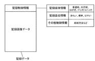
図2はかかる記録データの構成例を示した図である。記録データは、記録の制御を司る記録制御情報および記録すべき画像を示す記録画像データ(上記インデックスデータ)で構成されている。記録制御情報は、「記録媒体情報」、「記録品位情報」、給紙方法などの「その他制御情報」から構成されている。記録媒体情報には、記録の対象となる記録媒体の種類が記述されており、「普通紙」、「光沢紙」、「はがき」、「プリンタブルディスク」などのうちのいずれか1種類の記録媒体が選択されている。記録品位情報には、記録品位に対応する記録モードが記述されており、「きれい」、「標準」、「はやい」などのうちのいずれか1種の記録モードが選択されている。なお、これらの記録制御情報は、ホスト装置J0012のモニタおけるUI画面にてユーザが選択した内容に基づいて記述される。また、記録画像データは、前述のハーフトーン処理J0005によって生成された画像データが記述されているものとする。以上のようにして生成された記録データは、記録装置J0013へ供給される。 FIG. 2 is a diagram showing a configuration example of such recording data. The recording data includes recording control information for controlling recording and recording image data (the index data) indicating an image to be recorded. The recording control information includes “recording medium information”, “recording quality information”, and “other control information” such as a paper feeding method. The recording medium information describes the type of recording medium to be recorded, and any one type of recording medium such as “plain paper”, “glossy paper”, “postcard”, “printable disc”, etc. Is selected. In the recording quality information, a recording mode corresponding to the recording quality is described, and any one of the recording modes such as “clean”, “standard”, “fast”, and the like is selected. The recording control information is described based on the content selected by the user on the UI screen on the monitor of the host device J0012. Further, it is assumed that the recorded image data describes the image data generated by the above-described halftone process J0005. The recording data generated as described above is supplied to the recording device J0013.
記録装置J0013は、ホスト装置J0012から供給されたその記録データに対して、次に述べるドット配置パターン化処理J0007およびマスクデータ変換処理J0008を行う。 The printing apparatus J0013 performs the following dot arrangement patterning process J0007 and mask data conversion process J0008 on the printing data supplied from the host apparatus J0012.
1−6.ドット配置パターン化処理
上述したハーフトーン処理J0005では、256値の多値濃度情報(8ビットデータ)を9値の階調値情報(4ビットデータ)まで階調数を下げている。しかし、実際に記録装置J0013で記録するために使用されるデータは、インクドットを記録するか否かの2値データ(1ビットデータ)である。そこで、ドット配置パターン化処理J0007では、ハーフトーン処理J0005で処理された階調レベル0〜8の4ビットデータで表現される8画素ごとに、階調レベルに対応したドット配置パターンを割当てる。こうして、その8画素において1画素ごとにインクドットを記録させるか否か(ドットのオンまたはオフ)を決定する。つまり、1画素ごとに、ドットのオンを示す「1」またはドットのオフを示す「0」で表される1ビットの2値データを配置する。
1-6. In the dot arrangement patterning process described above, the number of gradations is reduced from 256-value multi-value density information (8-bit data) to 9-value gradation value information (4-bit data). However, the data actually used for recording by the recording apparatus J0013 is binary data (1 bit data) indicating whether or not to record ink dots. Therefore, in the dot arrangement patterning process J0007, a dot arrangement pattern corresponding to the gradation level is assigned to every 8 pixels represented by 4-bit data of
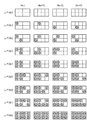
図3は、本実施形態のドット配置パターン化処理で変換する、階調レベル0〜8に対応する出力パターンを示している。図3中の左側に示した各レベル値は、ホスト装置におけるハーフトーン処理された4ビットデータの階調レベル0〜8に対応している。右側に配列した縦2画素×横4画素で構成される領域は、ハーフトーン処理された4ビットデータが表現する8画素分の領域に対応する。また、この領域の各画素は、ドットのオンまたはオフ(ドットの有無)が決定される最小単位に相当する。なお、本明細書において「画素」とは、階調表現可能な最小単位のことであり、複数ビットの多値データの画像処理(上記前段処理、後段処理、γ補正処理、ハーフトーン処理など)において処理が行われる領域の最小単位である。
FIG. 3 shows output patterns corresponding to
図3において、丸印が記入された画素はドットが記録される画素を示しており、レベル数が1つずつ上がるに従って記録されるドット数も1つずつ増加している。本実施形態においては、このようにしてオリジナル画像の濃度情報が反映されている。 In FIG. 3, pixels with circles indicate pixels where dots are recorded, and as the number of levels increases by one, the number of dots recorded increases by one. In this embodiment, the density information of the original image is reflected in this way.
また、図3において、(4n)〜(4n+3)は、対応する画像データの、記録領域における左端からの、横方向の画素の位置(記録位置)を示している。なお、nは1以上の整数であり、例えば、(4n)においてnが1の場合、対応する画像データは、記録領域において左端から横方向に1〜4画素(縦方向に2画素分)の領域に対応する画像データであることを示している。(4n)〜(4n+3)に応じて、各階調レベルで異なるドット配置パターンが用意されている。すなわち、同一の階調レベルの画像データが記録装置J0013に入力された場合にも、記録媒体上では(4n)〜(4n+3)に示した4種類のドット配置パターンが横方向に巡回されて割当てられる構成となっている。 In FIG. 3, (4n) to (4n + 3) indicate horizontal pixel positions (recording positions) from the left end in the recording area of the corresponding image data. Note that n is an integer equal to or greater than 1. For example, when n is 1 in (4n), the corresponding image data is 1 to 4 pixels in the horizontal direction from the left end in the recording area (2 pixels in the vertical direction). It shows that the image data corresponds to the area. Different dot arrangement patterns are prepared for each gradation level according to (4n) to (4n + 3). That is, even when image data having the same gradation level is input to the recording apparatus J0013, four types of dot arrangement patterns shown in (4n) to (4n + 3) are circulated in the horizontal direction and assigned on the recording medium. It has a configuration that can be.
本実施形態では、後述するように、ノズルが配列した記録ヘッドをノズルの配列方向と直交する方向に走査しながら記録を行う記録装置を用いている。図3においては、縦方向を記録ヘッドのノズルが配列する方向、横方向を記録ヘッドの走査方向としている。このように同一の階調レベルに対して複数の異なるドット配置で記録できる構成とすることで、ドット配置パターンの上段に位置するノズルと下段に位置するノズルとで吐出を分散すること、記録装置特有の様々なノイズを分散することなどができる。 In this embodiment, as will be described later, a recording apparatus that performs recording while scanning a recording head in which nozzles are arranged in a direction orthogonal to the nozzle arrangement direction is used. In FIG. 3, the vertical direction is the direction in which the nozzles of the recording head are arranged, and the horizontal direction is the scanning direction of the recording head. In this way, by recording with a plurality of different dot arrangements for the same gradation level, the discharge is distributed between the nozzles located in the upper stage and the nozzles located in the lower stage of the dot arrangement pattern. Various unique noises can be distributed.
以上説明したドット配置パターン化処理を終了した段階で、記録媒体に対するドットの配置パターンが全て決定される。 When the dot arrangement patterning process described above is completed, all dot arrangement patterns for the recording medium are determined.
1−7.マスクデータ変換処理
上述したドット配置パターン化処理J0007により、記録媒体上の各エリアに対するドットの有無は決定される。このため、このドット配置を示す2値データを記録ヘッドH1001の駆動回路(ヘッド駆動回路J0009)に入力すれば、所望の画像を記録することが可能である。この場合、記録媒体上の同一の走査領域に対する記録を1回の走査によって完成させる、いわゆる1パス記録により実行されうる。しかし、ここでは、記録媒体上の同一の走査領域に対して複数回の走査によって記録を完成させる、いわゆるマルチパス記録の例をとって説明する。
1-7. Mask data conversion process The dot arrangement patterning process J0007 described above determines the presence or absence of dots for each area on the recording medium. Therefore, if binary data indicating this dot arrangement is input to the drive circuit (head drive circuit J0009) of the print head H1001, a desired image can be printed. In this case, it can be executed by so-called one-pass printing, in which printing for the same scanning area on the printing medium is completed by one scan. However, a description will be given here of an example of so-called multi-pass printing in which printing is completed by a plurality of scans on the same scanning area on the printing medium.
図4は、マルチパス記録方法を説明するために、記録ヘッドおよび記録パターンを模式的に示したものである。本実施形態に適用される記録ヘッドH1001は実際には768個のノズルを有するが、ここでは簡単のため16個のノズルを有するものとして説明する。ノズルは、図のように第1〜第4の4つのノズル群に分割され、各ノズル群には4つずつのノズルが含まれている。マスクパターンP0002は、第1〜第4のマスクパターンP0002(a)〜P0002(d)で構成される。第1〜第4のマスクパターンP0002(a)〜P0002(d)は、それぞれ、第1〜第4のノズル群が記録可能なエリアを定義している。マスクパターンにおける黒塗りエリアは記録許容エリアを示し、白塗りエリアは非記録エリアを示している。第1〜第4のマスクパターンP0002(a)〜P0002(d)は互いに補完の関係にあり、これら4つのマスクパターンを重ね合わせると4×4のエリアに対応した領域の記録が完成される構成となっている。 FIG. 4 schematically shows a recording head and a recording pattern in order to explain the multipass recording method. The recording head H1001 applied to this embodiment actually has 768 nozzles, but here it will be described as having 16 nozzles for simplicity. As shown in the drawing, the nozzles are divided into first to fourth nozzle groups, and each nozzle group includes four nozzles. The mask pattern P0002 includes first to fourth mask patterns P0002 (a) to P0002 (d). The first to fourth mask patterns P0002 (a) to P0002 (d) define areas where the first to fourth nozzle groups can be recorded. The black area in the mask pattern indicates a recording allowable area, and the white area indicates a non-recording area. The first to fourth mask patterns P0002 (a) to P0002 (d) are complementary to each other, and when these four mask patterns are overlapped, recording of a region corresponding to a 4 × 4 area is completed. It has become.
P0003〜P0006で示した各パターンは、ある記録領域に重ねて記録走査を行うことによって記録画像を形成していく様子を示したものである。各記録走査が終了するたびに、記録媒体は図の矢印の方向にノズル群の幅分(この図では4ノズル分)ずつ搬送される。このように、この記録領域(各ノズル群の幅に対応する領域)は4回の記録走査によって記録画像が形成される。以上のように、記録媒体のある記録領域において画像が複数回の走査で複数のノズル群によって形成されることは、ノズルのばらつきや記録媒体の搬送精度のばらつきなどを低減させる効果がある。 Each pattern indicated by P0003 to P0006 shows a state in which a recorded image is formed by performing a recording scan over a certain recording area. At the end of each printing scan, the printing medium is conveyed by the width of the nozzle group (four nozzles in this figure) in the direction of the arrow in the figure. Thus, in this recording area (area corresponding to the width of each nozzle group), a recorded image is formed by four recording scans. As described above, when an image is formed by a plurality of nozzle groups in a plurality of scans in a recording area of the recording medium, there is an effect of reducing variations in nozzles, variations in conveyance accuracy of the recording medium, and the like.
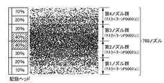
図5は、本実施形態に適用可能なマスクパターンの一例を示したものである。本実施形態で適用する記録ヘッドH1001は768個のノズルを有しており、4つのノズル群にはそれぞれ192個ずつのノズルが属している。マスクパターン大きさは、縦方向がノズル数と同等の768画素分、横方向は256画素分となっており、4つのノズル群それぞれに対応する4つのマスクパターンで互いに補完の関係を保つような構成となっている。 FIG. 5 shows an example of a mask pattern applicable to this embodiment. The recording head H1001 applied in this embodiment has 768 nozzles, and 192 nozzles belong to each of the four nozzle groups. The mask pattern size is 768 pixels equivalent to the number of nozzles in the vertical direction and 256 pixels in the horizontal direction, and the four mask patterns corresponding to each of the four nozzle groups maintain a complementary relationship with each other. It has a configuration.
ところで、本実施形態で適用するような、多数の小液滴を高周波数で吐出するようなインクジェット記録ヘッドにおいては、記録動作時に記録部近傍に気流が生じ、この気流が特にノズル列端部のノズルの吐出方向に影響を与えることが確認されている。このため、本実施形態のマスクパターンにおいては、図5からも判るように、各ノズル群また同一のノズル群の中でも、領域によって記録許容率の分布に偏りを持たせている。図5で示すように、ノズル列端部のノズルの記録許容率を中央部の記録許容率よりも小さくした構成のマスクパターンを適用することにより、端部のノズルにより吐出されるインク滴の着弾位置ずれによる弊害を目立たなくすることが可能となる。 By the way, in an ink jet recording head that discharges a large number of small droplets at a high frequency as applied in the present embodiment, an air flow is generated in the vicinity of the recording unit during a recording operation, and this air flow is particularly generated at the end of the nozzle row. It has been confirmed that the nozzle ejection direction is affected. For this reason, in the mask pattern of this embodiment, as can be seen from FIG. 5, the distribution of the printing allowance is biased depending on the region in each nozzle group or the same nozzle group. As shown in FIG. 5, by applying a mask pattern having a configuration in which the recording allowance of the nozzles at the end of the nozzle row is smaller than the recording allowance of the center, landing of ink droplets ejected by the nozzles at the end It is possible to make the harmful effects caused by the misalignment inconspicuous.
なお、マスクパターンで定められる記録許容率とは、マスクパターンを構成する記録許容エリアと非記録許容エリアの合計数に対する記録許容エリアの数の割合を百分率で表したものである。例えば、図4のマスクパターンP0002の黒塗りエリアは記録許容エリアに相当し、図4のマスクパターンP0002の白塗りエリアは非記録許容エリアに相当する。すなわち、マスクパターンの記録許容エリアをM個、非記録許容エリアをN個とすると、そのマスクパターンの記録許容率(%)は、M÷(M+N)×100となる。 The recording allowance defined by the mask pattern is a percentage of the number of recording allowance areas with respect to the total number of recording allowance areas and non-recording allowance areas constituting the mask pattern. For example, the blacked area of the mask pattern P0002 in FIG. 4 corresponds to a print allowable area, and the white painted area of the mask pattern P0002 in FIG. 4 corresponds to a non-printable area. That is, if the mask pattern recording allowable area is M and the non-recording allowable area is N, the mask pattern recording allowable ratio (%) is M ÷ (M + N) × 100.
本実施形態においては、図5で示したマスクデータが記録装置本体内のメモリに格納されている。そして、マスクデータ変換処理J0008においては、当該マスクデータと上述したドット配置パターン化処理で得られた2値データとの論理積を演算することにより、各記録走査での2値データが決定され、その2値データを駆動回路J0009へ送る。これにより、記録ヘッドH1001が駆動されて2値データに従ってインクが吐出される。 In the present embodiment, the mask data shown in FIG. 5 is stored in a memory in the recording apparatus main body. In the mask data conversion process J0008, binary data in each printing scan is determined by calculating a logical product of the mask data and the binary data obtained by the dot arrangement patterning process described above. The binary data is sent to the drive circuit J0009. As a result, the recording head H1001 is driven and ink is ejected according to the binary data.
なお、図1の記録システムは、前段処理J0002、後段処理J0003、γ補正処理J0004、ハーフトーン処理J0005および記録データ作成処理J0006がホスト装置J0012で実行される。そして、ドット配置パターン化処理J0007およびマスクデータ変換処理J0008が記録装置J0013で実行される。しかしながら、本発明はこのような形態に限定されない。例えば、ホスト装置J0012で実行しているJ0002〜J0005の処理の一部を記録装置J0013にて実行する形態であってもよいし、すべての処理をホスト装置J0012にて実行する形態であってもよい。あるいは、J0002〜J0008の処理を記録装置J0013にて実行する形態であってもよい。 In the recording system of FIG. 1, the host apparatus J0012 executes a pre-stage process J0002, a post-stage process J0003, a gamma correction process J0004, a halftone process J0005, and a print data creation process J0006. Then, a dot arrangement patterning process J0007 and a mask data conversion process J0008 are executed by the printing apparatus J0013. However, the present invention is not limited to such a form. For example, a part of the processes J0002 to J0005 executed by the host apparatus J0012 may be executed by the recording apparatus J0013, or all the processes may be executed by the host apparatus J0012. Good. Or the form which performs the process of J0002-J0008 with the recording apparatus J0013 may be sufficient.
2.記録装置の各機構部の構成
次に、本実施形態で適用する記録装置における各機構部の構成を説明する。本実施形態の記録装置は、各機構部の役割から、概して、給紙部、搬送部、排紙部、キャリッジ部、フラットパス記録部、およびクリーニング部等に分類することができ、これらは外装部に収納されている。
2. Configuration of Each Mechanism Unit of Recording Apparatus Next, the configuration of each mechanism section in the recording apparatus applied in the present embodiment will be described. The recording apparatus according to the present embodiment can be generally classified into a paper feeding unit, a conveyance unit, a paper discharge unit, a carriage unit, a flat path recording unit, a cleaning unit, and the like based on the role of each mechanism unit. It is stored in the part.
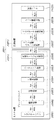
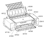
図6、図7、図8、図12および図13は、本実施形態で適用する記録装置の外観を示す斜視図である。ここで、図6は非使用時の記録装置を前面から見た状態である。図7は非使用時の記録装置を背面から見た状態である。図8は使用時の記録装置を前面から見た状態である。図12はフラットパス記録時の記録装置を前面から見た状態である。図13はフラットパス記録時の記録装置を背面から見た状態である。また、図9〜図11および図14〜図16は、記録装置本体の内部機構を説明するための図である。ここで、図9は記録装置本体の内部機構の右上部からの斜視図である。図10は記録装置本体の内部機構の左上部からの斜視図である。図11は記録装置本体の側断面図である。図14はフラットパス記録時における記録装置本体の内部機構の断面図である。図15はクリーニング部の斜視図である。図16はクリーニング部におけるワイピング機構の構成および動作を説明するための断面図である。 6, FIG. 7, FIG. 8, FIG. 12, and FIG. 13 are perspective views showing the external appearance of a recording apparatus applied in this embodiment. Here, FIG. 6 shows the recording apparatus when not in use as viewed from the front. FIG. 7 shows the recording apparatus when not in use as viewed from the back. FIG. 8 shows the recording apparatus in use as seen from the front. FIG. 12 shows the recording apparatus viewed from the front during flat pass recording. FIG. 13 shows a state in which the recording apparatus at the time of flat pass recording is viewed from the back side. FIGS. 9 to 11 and FIGS. 14 to 16 are diagrams for explaining the internal mechanism of the recording apparatus main body. Here, FIG. 9 is a perspective view from the upper right part of the internal mechanism of the recording apparatus main body. FIG. 10 is a perspective view from the upper left of the internal mechanism of the recording apparatus main body. FIG. 11 is a side sectional view of the recording apparatus main body. FIG. 14 is a cross-sectional view of the internal mechanism of the recording apparatus main body during flat pass recording. FIG. 15 is a perspective view of the cleaning unit. FIG. 16 is a cross-sectional view for explaining the configuration and operation of the wiping mechanism in the cleaning unit.
以下、これらの図面を適宜参照しながら、各部を順次説明する。 Hereinafter, each part will be sequentially described with reference to these drawings as appropriate.
2−1.外装部(図6、図7)
外装部は、給紙部、搬送部、排紙部、キャリッジ部、クリーニング部、フラットパス部およびウエット液転写部の周りを覆うように取り付けられている。外装部は主に、下ケースM7080、上ケースM7040、アクセスカバーM7030、コネクタカバーおよびフロントトレイM7010から構成されている。
2-1. Exterior part (Figs. 6 and 7)
The exterior portion is attached so as to cover the periphery of the paper feed portion, the transport portion, the paper discharge portion, the carriage portion, the cleaning portion, the flat path portion, and the wet liquid transfer portion. The exterior portion mainly includes a lower case M7080, an upper case M7040, an access cover M7030, a connector cover, and a front tray M7010.
下ケースM7080の下部には、不図示の排紙トレイレールが設けられており、分割された排紙トレイM3160が収納可能に構成されている。また、フロントトレイM7010は、非使用時に排紙口を塞ぐ構成になっている。 A lower discharge tray rail (not shown) is provided below the lower case M7080, and the divided discharge tray M3160 can be stored. Further, the front tray M7010 is configured to close the paper discharge port when not in use.
上ケースM7040には、アクセスカバーM7030が取り付けられており、回動可能に構成されている。上ケースの上面の一部は開口部を有しており、この位置で、インクタンクH1900および記録ヘッドH1001(図21)が交換可能となるように構成されている。なお、本実施形態の記録装置においては、記録ヘッドH1001は、1色のインクを吐出可能な吐出部を複数色分、一体的に構成したユニットの形態であり、インクタンクH1900が色毎に独立に着脱可能なヘッドカートリッジになっている。上ケースM7040には、アクセスカバーM7030の開閉を検知するための不図示のドアスイッチレバー、LEDの光を伝達し表示するLEDガイドM7060が設けられている。さらに、上ケースM7040には、電源キーE0018、リジュームキーE0019およびフラットパスキーE3004などが設けられている。また、多段式の給紙トレイM2060が回動可能に取り付けられており、給紙部が使われない時は、給紙トレイM2060を収納することにより、給紙部のカバーにもなるように構成されている。 An access cover M7030 is attached to the upper case M7040 and is configured to be rotatable. A part of the upper surface of the upper case has an opening, and the ink tank H1900 and the recording head H1001 (FIG. 21) can be exchanged at this position. In the recording apparatus according to the present embodiment, the recording head H1001 is in the form of a unit in which a plurality of ejection portions capable of ejecting one color of ink are integrally configured, and the ink tank H1900 is independent for each color. It is a removable head cartridge. The upper case M7040 is provided with a door switch lever (not shown) for detecting opening / closing of the access cover M7030 and an LED guide M7060 for transmitting and displaying the light of the LED. Further, the upper case M7040 is provided with a power key E0018, a resume key E0019, a flat pass key E3004, and the like. Further, the multi-stage type paper feed tray M2060 is rotatably attached, and when the paper feed unit is not used, the paper feed tray M2060 is accommodated so that it also serves as a cover for the paper feed unit. Has been.
上ケースM7040と下ケースM7080は、弾性を持った勘合爪で取り付けられており、その間のコネクタ部分が設けられている部分を、不図示のコネクタカバーが覆っている。 The upper case M7040 and the lower case M7080 are attached with elastic fitting claws, and a connector cover (not shown) covers a portion where the connector portion is provided therebetween.
2−2.給紙部(図8、図11)
給紙部は、記録媒体を積載する圧板M2010、記録媒体を1枚ずつ給紙する給紙ローラM2080、記録媒体を分離する分離ローラM2041、記録媒体を積載位置に戻すための戻しレバーM2020などがベースM2000に取り付けられている。
2-2. Paper feed unit (FIGS. 8 and 11)
The paper feeding unit includes a pressure plate M2010 for stacking recording media, a paper feeding roller M2080 for feeding recording media one by one, a separation roller M2041 for separating the recording media, a return lever M2020 for returning the recording media to the stacking position, and the like. It is attached to the base M2000.
2−3.搬送部(図8〜図11)
曲げ起こした板金からなるシャーシM1010には、記録媒体を搬送する搬送ローラM3060とペーパエンドセンサ(以下PEセンサと称す)E0007が回動可能に取り付けられている。搬送ローラM3060は、金属軸の表面にセラミックの微小粒がコーティングされており、金属軸を不図示の軸受けが受ける状態で、シャーシM1010に取り付けられている。搬送ローラM3060にはローラテンションバネ(不図示)が設けられており、これが搬送ローラM3060を付勢することにより、回転時に適量の負荷を与えて安定した搬送が行えるようになっている。
2-3. Conveying section (FIGS. 8 to 11)
A conveyance roller M3060 for conveying a recording medium and a paper end sensor (hereinafter referred to as a PE sensor) E0007 are rotatably attached to a chassis M1010 made of a bent metal sheet. The transport roller M3060 is attached to the chassis M1010 in a state where the surface of the metal shaft is coated with ceramic fine particles and the metal shaft is received by a bearing (not shown). The conveyance roller M3060 is provided with a roller tension spring (not shown), and this energizes the conveyance roller M3060 so that an appropriate amount of load is applied during rotation so that stable conveyance can be performed.
搬送ローラM3060には、従動する複数のピンチローラM3070が当接して設けられている。ピンチローラM3070は、ピンチローラホルダM3000に保持されているが、不図示のピンチローラバネによって付勢されることで、搬送ローラM3060に圧接し、ここで記録媒体の搬送力を生み出している。この時、ピンチローラホルダM3000の回転軸は、シャーシM1010の軸受けに取り付けられ、この位置を中心に回転する。 A plurality of driven pinch rollers M3070 are provided in contact with the transport roller M3060. The pinch roller M3070 is held by the pinch roller holder M3000, but is urged by a pinch roller spring (not shown) to be brought into pressure contact with the conveyance roller M3060, and generates a conveyance force for the recording medium. At this time, the rotation shaft of the pinch roller holder M3000 is attached to the bearing of the chassis M1010 and rotates around this position.
記録媒体が搬送されてくる搬送部の入口には、記録媒体をガイドするためのペーパガイドフラッパM3030およびプラテンM3040が設けられている。また、ピンチローラホルダM3000にはPEセンサレバーM3021が設けられており、PEセンサレバーM3021は記録媒体の先端および後端の検出をPEセンサE0007に伝える役割を果たす。プラテンM3040は、シャーシM1010に取り付けられ、位置決めされている。ペーパガイドフラッパM3030は、不図示の軸受け部を中心に回転可能で、シャーシM1010に当接することで位置決めされる。 A paper guide flapper M3030 and a platen M3040 for guiding the recording medium are provided at the entrance of the conveyance unit to which the recording medium is conveyed. The pinch roller holder M3000 is provided with a PE sensor lever M3021, and the PE sensor lever M3021 plays a role of transmitting the detection of the leading edge and the trailing edge of the recording medium to the PE sensor E0007. The platen M3040 is attached to the chassis M1010 and positioned. The paper guide flapper M3030 can rotate around a bearing portion (not shown) and is positioned by contacting the chassis M1010.
搬送ローラM3060の記録媒体搬送方向における下流側には、図21で示される記録ヘッドH1001が設けられている。 A recording head H1001 shown in FIG. 21 is provided on the downstream side of the conveyance roller M3060 in the recording medium conveyance direction.
上記構成における搬送の過程を説明する。搬送部に送られてきた記録媒体は、ピンチローラホルダM3000およびペーパガイドフラッパM3030に案内されて、搬送ローラM3060とピンチローラM3070とのローラ対に送られる。この時、PEセンサレバーM3021が、記録媒体の先端を検知して、これにより記録媒体に対する記録位置が求められる。搬送ローラM3060とピンチローラM3070とからなるローラ対は、LFモータE0002の駆動により回転され、この回転により記録媒体がプラテンM3040上を搬送される。プラテンM3040には、搬送基準面となるリブが形成されており、このリブにより、記録ヘッドH1001と記録媒体表面との間のギャップが管理されている。また同時に、当該リブが、後述する排紙部と合わせて、記録媒体の波打ちを抑制する役割も果たしている。 The conveyance process in the above configuration will be described. The recording medium sent to the conveyance unit is guided by the pinch roller holder M3000 and the paper guide flapper M3030, and is sent to the roller pair of the conveyance roller M3060 and the pinch roller M3070. At this time, the PE sensor lever M3021 detects the leading edge of the recording medium, and thereby the recording position with respect to the recording medium is obtained. A roller pair composed of a conveyance roller M3060 and a pinch roller M3070 is rotated by driving of the LF motor E0002, and the recording medium is conveyed on the platen M3040 by this rotation. The platen M3040 is provided with a rib serving as a conveyance reference surface, and a gap between the recording head H1001 and the recording medium surface is managed by the rib. At the same time, the ribs play a role of suppressing the undulation of the recording medium together with a paper discharge unit described later.
搬送ローラM3060が回転するための駆動力は、例えばDCモータからなるLFモータE0002の回転力が、不図示のタイミングベルトを介して、搬送ローラM3060の軸上に配設されたプーリM3061に伝達されることによって得られている。また、搬送ローラM3060の軸上には、搬送ローラM3060による搬送量を検出するためのコードホイールM3062が設けられている。シャーシM1010には、コードホイールM3062に形成されたマーキングを読み取るためのエンコードセンサM3090が設けられている。なお、コードホイールM3062に形成されたマーキングは、150〜300lpi(ライン/インチ)のピッチで形成されているものとする。 The driving force for rotating the transport roller M3060 is transmitted, for example, to the pulley M3061 provided on the shaft of the transport roller M3060 via a timing belt (not shown) from the LF motor E0002 made of a DC motor. It is obtained by doing. A code wheel M3062 for detecting the amount of conveyance by the conveyance roller M3060 is provided on the axis of the conveyance roller M3060. The chassis M1010 is provided with an encode sensor M3090 for reading the marking formed on the code wheel M3062. The markings formed on the code wheel M3062 are formed at a pitch of 150 to 300 lpi (line / inch).
2−4.排紙部(図8〜図11)
排紙部は、第1の排紙ローラM3100および第2の排紙ローラM3110、複数の拍車M3120およびギア列などから構成されている。第1の排紙ローラM3100は、金属軸に複数のゴム部を設けて構成されている。第1の排紙ローラM3100の駆動は、搬送ローラM3060の駆動がアイドラギアを介して第1の排紙ローラM3100まで伝達されることによって行われる。第2の排紙ローラM3110は、樹脂の軸にエラストマの弾性体M3111を複数取り付けた構成になっている。第2の排紙ローラM3110の駆動は、第1の排紙ローラM3100の駆動が、アイドラギアを介して伝達することによって行われる。
2-4. Paper discharge unit (FIGS. 8 to 11)
The paper discharge unit includes a first paper discharge roller M3100, a second paper discharge roller M3110, a plurality of spurs M3120, a gear train, and the like. The first paper discharge roller M3100 is configured by providing a plurality of rubber portions on a metal shaft. The first paper discharge roller M3100 is driven by transmitting the driving of the transport roller M3060 to the first paper discharge roller M3100 via an idler gear. The second paper discharge roller M3110 has a structure in which a plurality of elastomer elastic bodies M3111 are attached to a resin shaft. The second paper discharge roller M3110 is driven by transmitting the drive of the first paper discharge roller M3100 via an idler gear.
拍車M3120は、周囲に凸形状を複数設けた例えばSUSからなる円形の薄板を樹脂部と一体としたもので、コイルバネを棒状に設けた拍車バネによって拍車ホルダM3130に複数取り付けられている。また、拍車バネは、拍車M3120を排紙ローラM3100およびM3110に対し所定圧で当接させている。このような構成によって、拍車M3120は2つの排紙ローラM3100およびM3110に従動して回転可能となっている。拍車M3120のいくつかは、第1の排紙ローラM3100のゴム部或いは第2の排紙ローラM3110の弾性体M3111の位置に設けられており、主に記録媒体の搬送力を生み出す役割を果たしている。また、その他のいくつかは、ゴム部あるいは弾性体M3111が無い位置に設けられ、主に記録時の記録媒体の浮き上がりを抑える役割を果たしている。 The spur M3120 is formed by integrating a circular thin plate made of, for example, SUS with a plurality of convex shapes around the resin portion, and a plurality of spurs M3120 are attached to the spur holder M3130 by a spur spring in which a coil spring is provided in a rod shape. The spur spring causes the spur M3120 to abut against the paper discharge rollers M3100 and M3110 with a predetermined pressure. With such a configuration, the spur M3120 can be rotated following the two paper discharge rollers M3100 and M3110. Some of the spurs M3120 are provided at the position of the rubber portion of the first paper discharge roller M3100 or the elastic body M3111 of the second paper discharge roller M3110, and mainly play a role of generating the conveyance force of the recording medium. . In addition, some others are provided at positions where the rubber part or the elastic body M3111 is not present, and mainly play a role of suppressing the lifting of the recording medium during recording.
また、ギア列は、搬送ローラM3060の駆動を排紙ローラM3100およびM3110に伝達する役割を果たしている。 Further, the gear train plays a role of transmitting the driving of the transport roller M3060 to the paper discharge rollers M3100 and M3110.
以上の構成によって、画像が記録された記録媒体は、第1の排紙ローラM3110と拍車M3120とのニップに挟まれ、搬送されて排紙トレイM3160に排出される。排紙トレイM3160は、複数に分割され、後述する下ケースM7080の下部に収納できる構成になっている。排紙トレイM3160の使用時はこれを引出して使用する。また、排紙トレイM3160は、先端に向けて高さが上がり、更にその両端は高い位置に保持されるよう設計されており、排出された記録媒体の積載性を向上し、記録面の擦れなどを防止している。 With the above configuration, the recording medium on which the image is recorded is sandwiched between the nip between the first paper discharge roller M3110 and the spur M3120, conveyed, and discharged to the paper discharge tray M3160. The paper discharge tray M3160 is divided into a plurality of parts and can be stored in a lower part of a lower case M7080 described later. When the paper discharge tray M3160 is used, it is pulled out and used. Further, the discharge tray M3160 is designed such that its height increases toward the leading end, and both ends thereof are held at high positions, improving the stackability of the discharged recording medium, rubbing the recording surface, and the like. Is preventing.
2−5.キャリッジ部(図9〜図11)
キャリッジ部は、記録ヘッドH1001を取り付けるためのキャリッジM4000を有しており、キャリッジM4000は、ガイドシャフトM4020およびガイドレールM1011によって支持されている。ガイドシャフトM4020は、シャーシM1010に取り付けられており、記録媒体の搬送方向と直交する方向にキャリッジM4000を往復走査させるように案内支持している。ガイドレールM1011は、シャーシM1010に一体に形成されており、キャリッジM4000の後端を保持して記録ヘッドH1001と記録媒体との隙間を維持する役割を果たしている。また、ガイドレールM1011のキャリッジM4000との摺動側には、ステンレス等の薄板からなる摺動シートM4030が張設され、記録装置の摺動音の低減化を図っている。
2-5. Carriage part (FIGS. 9 to 11)
The carriage unit has a carriage M4000 for mounting the recording head H1001, and the carriage M4000 is supported by a guide shaft M4020 and a guide rail M1011. The guide shaft M4020 is attached to the chassis M1010 and guides and supports the carriage M4000 so as to reciprocate in a direction orthogonal to the recording medium conveyance direction. The guide rail M1011 is formed integrally with the chassis M1010, and holds the rear end of the carriage M4000 and plays a role of maintaining a gap between the recording head H1001 and the recording medium. Further, a sliding sheet M4030 made of a thin plate of stainless steel or the like is stretched on the sliding side of the guide rail M1011 with respect to the carriage M4000 so as to reduce the sliding noise of the recording apparatus.
キャリッジM4000は、シャーシM1010に取り付けられたキャリッジモータE0001によりタイミングベルトM4041を介して駆動される。また、タイミングベルトM4041は、アイドルプーリM4042によって張られた状態で支持されている。さらに、タイミングベルトM4041は、キャリッジM4000とゴム等からなるキャリッジダンパを介して結合されており、キャリッジモータE0001等の振動を減衰することで、記録される画像のむら等を低減している。 The carriage M4000 is driven via a timing belt M4041 by a carriage motor E0001 attached to the chassis M1010. Further, the timing belt M4041 is supported in a state of being stretched by an idle pulley M4042. Further, the timing belt M4041 is coupled to the carriage M4000 via a carriage damper made of rubber or the like, and the unevenness of the recorded image is reduced by attenuating the vibration of the carriage motor E0001 or the like.
また、キャリッジM4000の位置を検出するためのエンコーダスケールE0005(図18参照)が、タイミングベルトM4041と平行に設けられている。エンコーダスケールE0005上には、150lpi〜300lpiのピッチでマーキングが形成されている。そして、このマーキングを読み取るためのエンコーダセンサE0004(図18参照)が、キャリッジM4000に搭載されたキャリッジ基板E0013(図18参照)に設けられている。キャリッジ基板E0013には、記録ヘッドH1001と電気的な接続を行うためのヘッドコネクタE0101も設けられている。また、キャリッジM4000には、メイン基板E0014から記録ヘッドH1001へ駆動信号を伝えるためのフレキシブルケーブルE0012(図18参照)が接続されている。 An encoder scale E0005 (see FIG. 18) for detecting the position of the carriage M4000 is provided in parallel with the timing belt M4041. On the encoder scale E0005, markings are formed at a pitch of 150 lpi to 300 lpi. An encoder sensor E0004 (see FIG. 18) for reading the marking is provided on the carriage substrate E0013 (see FIG. 18) mounted on the carriage M4000. The carriage substrate E0013 is also provided with a head connector E0101 for electrical connection with the recording head H1001. In addition, a flexible cable E0012 (see FIG. 18) for transmitting a drive signal from the main board E0014 to the recording head H1001 is connected to the carriage M4000.
記録ヘッドH1001をキャリッジM4000に固定するため、記録ヘッドH1001をキャリッジM4000に押し付けながら位置決めするための不図示の突き当て部と所定の位置に固定するための不図示の押圧手段とがキャリッジ上に設けられている。押圧手段は、ヘッドセットレバーM4010に搭載され、記録ヘッドH1001をセットする際に、ヘッドセットレバーM4010が回転支点を中心に回されることで記録ヘッドH1001の位置を固定する構成になっている。 In order to fix the recording head H1001 to the carriage M4000, an abutting portion (not shown) for positioning the recording head H1001 against the carriage M4000 and a pressing means (not shown) for fixing the recording head H1001 at a predetermined position are provided on the carriage. It has been. The pressing means is mounted on the head set lever M4010, and when the recording head H1001 is set, the position of the recording head H1001 is fixed by turning the head set lever M4010 around the rotation fulcrum.
さらに、キャリッジM4000には、CD−Rなどへ記録を行う際や記録媒体の端部を検出する際などにおける記録媒体の位置検出用として、反射型の光センサからなる位置検出センサが取り付けられている。位置検出センサは、発光素子が発光して照射された照射光の反射光を受光することで、キャリッジM4000の現在位置を検出することができる。 Further, the carriage M4000 is provided with a position detection sensor composed of a reflection type optical sensor for detecting the position of the recording medium when recording on a CD-R or the like or detecting the end of the recording medium. Yes. The position detection sensor can detect the current position of the carriage M4000 by receiving reflected light of the irradiation light emitted from the light emitting element.
上記構成のキャリッジ部により、記録媒体に画像形成する際、搬送ローラM3060およびピンチローラM3070からなるローラ対が、記録媒体を搬送して記録媒体の搬送方向の位置決めをする。また、キャリッジモータE0001によりキャリッジM4000を上記搬送方向と直交する方向に移動させて、記録ヘッドH1001を目的の画像形成位置に配置させる。位置決めされた記録ヘッドH1001は、メイン基板E0014からの信号に従って、記録媒体に対しインクを吐出する。本実施形態の記録装置は、キャリッジM4000を移動させて記録ヘッドH1001による記録走査(主走査)と、搬送ローラM3060により記録媒体を走査方向と直交する方向に搬送する副走査とを交互に繰り返すことにより記録媒体上に画像を形成する。 When an image is formed on a recording medium by the carriage section having the above-described configuration, a roller pair including a conveyance roller M3060 and a pinch roller M3070 conveys the recording medium and positions the recording medium in the conveyance direction. Also, the carriage motor E0001 moves the carriage M4000 in a direction perpendicular to the transport direction, and the recording head H1001 is disposed at a target image forming position. The positioned recording head H1001 ejects ink to the recording medium in accordance with a signal from the main substrate E0014. The recording apparatus according to the present embodiment alternately repeats recording scanning (main scanning) by the recording head H1001 by moving the carriage M4000 and sub-scanning by which the recording medium is conveyed in a direction orthogonal to the scanning direction by the conveyance roller M3060. Thus, an image is formed on the recording medium.
2−6.フラットパス記録部(図12〜図14)
給紙部からの給紙は、図11に示したように記録媒体が通る経路がピンチローラに達するまで曲がっているため、記録媒体を曲げた状態で行われることになる。従って、例えば0.5mm以上の厚い記録媒体を給紙部から給紙しようとすると、曲げられた記録媒体の反力による給紙抵抗が増えて給紙が行えない場合がある。また、給紙が可能であっても、排紙後の記録媒体が曲がったままとなったり、折れたりすることもある。
2-6. Flat pass recording unit (FIGS. 12 to 14)
Paper feeding from the paper feeding unit is performed in a state where the recording medium is bent because the path through which the recording medium passes is bent until reaching the pinch roller as shown in FIG. Therefore, for example, when a thick recording medium of 0.5 mm or more is to be fed from the sheet feeding unit, the sheet feeding resistance due to the reaction force of the bent recording medium may increase and the sheet feeding may not be performed. Even if paper can be fed, the recording medium after being ejected may remain bent or bend.
厚い記録媒体などの曲げたくない記録媒体や、CD−Rなどの曲げることのできない記録媒体に対して記録を行うのがフラットパス記録である。ここで、フラットパス記録を行う記録装置には本体背面のスリット上の開口部から手差し給紙で記録媒体を本体のピンチローラにニップさせて記録を行う形態のものがある。しかし、本実施形態のフラットパス記録は、記録媒体を本体手前の開口部(排紙口)から記録位置まで給紙してスイッチバックしてから記録を行う形態のものである。 Flat-pass recording is performed on a recording medium that does not want to bend, such as a thick recording medium, or a recording medium that cannot be bent, such as a CD-R. Here, there is a recording apparatus that performs flat-pass recording in which recording is performed by manually feeding a recording medium to a pinch roller of the main body from an opening on a slit on the back of the main body. However, the flat pass recording according to the present embodiment is a mode in which recording is performed after a recording medium is fed from an opening (discharge port) in front of the main body to a recording position and switched back.
フロントトレイM7010は、通常記録した記録媒体を数十枚程度積載しておくためのトレイを兼ねるため、排紙部より下方にある(図8)。フラットパス記録時には、記録媒体を排紙口から水平に、通常の搬送方向とは反対方向に給紙するために、フロントトレイM7010を排紙口の位置まで上げる(図12)。フロントトレイM7010には不図示のフック等が設けられており、フラットパス給紙位置にフロントトレイを固定可能である。フロントトレイM7010がフラットパス記録位置にあることはセンサで検知可能であり、この検知に応じてフラットパス記録モードと判断することができる。 The front tray M7010 serves as a tray for stacking about several tens of normally recorded recording media and is located below the paper discharge unit (FIG. 8). During flat-pass recording, the front tray M7010 is raised to the position of the paper discharge port in order to feed the recording medium horizontally from the paper discharge port in the direction opposite to the normal transport direction (FIG. 12). The front tray M7010 is provided with a hook or the like (not shown), and the front tray can be fixed at the flat path paper feed position. The presence of the front tray M7010 at the flat pass recording position can be detected by a sensor, and the flat pass recording mode can be determined according to this detection.
フラットパス記録モードでは、記録媒体をフロントトレイM7010に載せて排紙口から記録媒体を挿入する。このため、まずフラットパスキーE3004を操作することによって、想定している記録媒体の厚みより高い位置まで、拍車ホルダM3130とピンチローラホルダM3000とを不図示の機構により持ち上げる。またリアトレイボタンM7110を押すことによってリアトレイM7090を開き、さらにリアサブトレイM7091をV字に開くことも可能である(図13)。リアトレイM7090およびリアサブトレイM7091は、長い記録媒体を本体前面から挿入した場合は本体背面から突出するので、長い記録媒体を本体背面でも支えるためのトレイである。厚い記録媒体は記録中にフラットな姿勢を保たないとヘッドフェイス面と擦れたり、搬送負荷が変化したりすることから記録品位に影響を及ぼすおそれがあるので、これらのトレイを設けることは有効である。しかし本体背面からはみ出ない程度の長さの記録媒体であれば、リアトレイM7090等を開く必要はない。 In the flat pass recording mode, the recording medium is placed on the front tray M7010 and the recording medium is inserted from the paper discharge outlet. Therefore, by first operating the flat pass key E3004, the spur holder M3130 and the pinch roller holder M3000 are lifted by a mechanism (not shown) to a position higher than the assumed thickness of the recording medium. Further, the rear tray M7090 can be opened by pressing the rear tray button M7110, and the rear subtray M7091 can be opened in a V shape (FIG. 13). The rear tray M7090 and the rear sub-tray M7091 are trays for supporting a long recording medium also on the back of the main body, since the rear recording tray protrudes from the back of the main body when a long recording medium is inserted from the front of the main body. If a thick recording medium does not maintain a flat posture during recording, it may rub against the head face surface or change the transport load, which may affect the recording quality, so it is effective to install these trays. It is. However, if the recording medium has a length that does not protrude from the back of the main body, the rear tray M7090 or the like need not be opened.
以上によって、記録媒体を排紙口から本体内に挿入可能となる。記録媒体の後端部(ユーザに最も近く位置する手前側の端部)と右端部とをフロントトレイM7010のマーカ位置に揃えて、フロントトレイM7010に載せる。 As described above, the recording medium can be inserted into the main body from the paper discharge port. The rear end of the recording medium (the end on the near side closest to the user) and the right end are aligned with the marker position of the front tray M7010 and placed on the front tray M7010.
ここで再度フラットパスキーE3004を操作すると、拍車ホルダM3130が降りて排紙ローラM3100およびM3110と拍車M3120とで記録媒体をニップする。その後、排紙ローラM3100およびM3110で記録媒体を所定量本体内に引き込む(通常記録時の搬送方向とは逆方向)。最初に記録媒体をセットした際に記録媒体の手前側の端部(後端部)を揃えているので、短い記録媒体の前端部(ユーザから見て最も奥側の端部)は搬送ローラM3060まで届いていないことがある。従って所定量とは、想定している一番短い記録媒体の後端が搬送ローラM3060に届くまでの距離とする。所定量送られた記録媒体は搬送ローラM3060に届いているので、その位置でピンチローラホルダM3000を降ろして、搬送ローラM3060とピンチローラM3070とで記録媒体をニップさせる。そして記録媒体をさらに送り、その後端部が搬送ローラM3060とピンチローラM3070とでニップされるようにする。これで記録媒体のフラットパス記録のための給紙が終了したことになる(記録待機位置)。 When the flat pass key E3004 is operated again here, the spur holder M3130 descends and the recording medium is nipped between the paper discharge rollers M3100 and M3110 and the spur M3120. Thereafter, the recording medium is pulled into the main body by a predetermined amount by the paper discharge rollers M3100 and M3110 (the direction opposite to the transport direction during normal recording). When the recording medium is set for the first time, the front end (rear end) of the recording medium is aligned, so the front end of the short recording medium (end farthest from the user's end) is the transport roller M3060. May not reach. Accordingly, the predetermined amount is a distance until the rear end of the assumed shortest recording medium reaches the conveyance roller M3060. Since the recording medium fed by a predetermined amount reaches the conveying roller M3060, the pinch roller holder M3000 is lowered at that position, and the recording medium is nipped by the conveying roller M3060 and the pinch roller M3070. Then, the recording medium is further fed so that the rear end portion is nipped by the conveying roller M3060 and the pinch roller M3070. This completes the feeding of the recording medium for flat path recording (recording standby position).
排紙ローラM3100およびM3110と拍車M3120とのニップ力は、通常記録時の排紙時に形成画像に影響を与えないよう、比較的低く設定されている。従って、フラットパス記録時には記録を行うまでに記録媒体の位置がずれてしまうおそれがある。しかし本実施形態では、ニップ力が比較的高い搬送ローラM3060とピンチローラM3070とによって記録媒体をニップさせるので、記録媒体のセット位置が確保される。また、記録媒体を上記所定量だけ本体内に送るとき、プラテンM3040と拍車ホルダM3130の間にあるフラットパス紙検知センサM3170で記録媒体の後端位置(記録時の前端位置となる)を検知することができる。 The nip force between the paper discharge rollers M3100 and M3110 and the spur M3120 is set to be relatively low so as not to affect the formed image during paper discharge during normal recording. Accordingly, there is a risk that the position of the recording medium may be shifted before recording is performed during flat pass recording. However, in the present embodiment, the recording medium is nipped by the conveying roller M3060 and the pinch roller M3070 having a relatively high nip force, so that the setting position of the recording medium is secured. Further, when the recording medium is fed into the main body by the predetermined amount, the rear end position of the recording medium (the front end position at the time of recording) is detected by the flat path paper detection sensor M3170 located between the platen M3040 and the spur holder M3130. be able to.
記録媒体が上記記録待機位置に設定されると、記録コマンドを実行する。すなわち、記録ヘッドH1001による記録位置まで搬送ローラM3060で記録媒体を搬送し、後は通常の記録動作と同じように記録を行い、記録後フロントトレイM7010に排紙することになる。 When the recording medium is set at the recording standby position, a recording command is executed. In other words, the recording medium is transported by the transport roller M3060 to the recording position by the recording head H1001, and thereafter, recording is performed in the same manner as the normal recording operation, and the paper is discharged to the front tray M7010 after recording.
フラットパス記録をさらに行いたい場合は、記録した記録媒体をフロントトレイM7010から取り出し、次の記録媒体をセットして、前述の処理を繰り返せばよい。一方、フラットパス記録を終了する場合は、フロントトレイM7010を通常記録位置に戻すことによって通常記録モードに戻すことができる。 If further flat pass recording is desired, the recorded recording medium is taken out from the front tray M7010, the next recording medium is set, and the above-described processing is repeated. On the other hand, when the flat pass recording is ended, the normal recording mode can be restored by returning the front tray M7010 to the normal recording position.
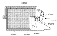
2−7.クリーニング部(図15、図16)
クリーニング部は記録ヘッドH1001のクリーニングを行うための機構である。ポンプM5000、記録ヘッドH1001内のインクの乾燥を抑えるためのキャップM5010、記録ヘッドH1001のノズル形成面をクリーニングするためのブレードM5020などから構成されている。
2-7. Cleaning unit (Figs. 15 and 16)
The cleaning unit is a mechanism for cleaning the recording head H1001. A pump M5000, a cap M5010 for suppressing the drying of ink in the recording head H1001, a blade M5020 for cleaning the nozzle forming surface of the recording head H1001, and the like.
クリーニング部には、専用のクリーニングモータE0003が配されている。クリーニングモータE0003には、不図示のワンウェイクラッチが設けられており、一方向の回転でポンプM5000を作動させ、もう一方向の回転ではブレードM5020の移動およびキャップM5010の昇降を行わせるようになっている。 A dedicated cleaning motor E0003 is disposed in the cleaning unit. The cleaning motor E0003 is provided with a one-way clutch (not shown) that operates the pump M5000 by rotating in one direction, and moves the blade M5020 and moves the cap M5010 up and down by rotating in the other direction. Yes.
キャップM5010はモータE0003から不図示の昇降機構を介して昇降可能に駆動される。上昇した位置では、記録ヘッドH1001のノズル形成面に設けられた数個の吐出部ごとにキャッピングを施し、非記録動作時等において記録ヘッドH1001の保護、または吸引回復などを行うことが可能である。また、記録動作時には記録ヘッドH1001との干渉を避けるため下降した位置に移動され、またノズル形成面と対向させることによって予備吐出を受けることが可能である。例えば記録ヘッドH1001に10個の吐出部が設けられ、5個の吐出部ごとに一括してキャッピングを施すことが可能となるよう、図15の例ではキャップM5010は2つ設けられている。 The cap M5010 is driven from the motor E0003 so as to be lifted and lowered via a lift mechanism (not shown). At the raised position, capping is performed for each of several ejection portions provided on the nozzle formation surface of the recording head H1001, and the recording head H1001 can be protected or recovered by suction during a non-recording operation. . Further, during the recording operation, it is moved to a lowered position in order to avoid interference with the recording head H1001, and it is possible to receive preliminary discharge by facing the nozzle forming surface. For example, in the example of FIG. 15, two caps M5010 are provided so that the recording head H1001 is provided with ten ejection units and the capping can be performed collectively for every five ejection units.
ゴム等の弾性部材でなるワイパ部M5020はワイパホルダH5021に固定されている。ワイパホルダH5021は、吐出部におけるノズルの配列方向である図16のY方向(+Y方向)および逆方向(−Y方向)に移動可能である。そして、記録ヘッドH1001がホームポジションに到達したときに、−Y方向にワイパホルダ25が移動することによって、ワイピングが可能である。ワイピング動作が終了すると、キャリッジをワイピング領域の外に退避させてから、ワイパがノズル形成面などと干渉しない位置に戻す。なお、本例のワイパ部M5020には、全吐出部のノズル形成面を含む記録ヘッドH1001のノズル形成面全体をワイピングするワイパブレードM5020Aが設けられている。さらに、5つの吐出部のノズル形成面ごとにノズル近傍をワイピングする2つのワイパブレードM5020BおよびM5020Cが設けられている。 A wiper part M5020 made of an elastic member such as rubber is fixed to a wiper holder H5021. The wiper holder H5021 is movable in the Y direction (+ Y direction) and the reverse direction (−Y direction) in FIG. When the recording head H1001 reaches the home position, the wiper holder 25 moves in the −Y direction, so that wiping is possible. When the wiping operation is completed, the carriage is retracted out of the wiping area and then returned to a position where the wiper does not interfere with the nozzle forming surface or the like. Note that the wiper unit M5020 of this example is provided with a wiper blade M5020A for wiping the entire nozzle formation surface of the recording head H1001 including the nozzle formation surfaces of all ejection units. Further, two wiper blades M5020B and M5020C for wiping the vicinity of the nozzles are provided for each nozzle formation surface of the five ejection portions.
そして、ワイピング後には、ワイパ部M5020がブレードクリーナM5060に当接することにより、ワイパブレードM5020A〜M5020Cに付着したインクなどを除去することができる構成になっている。また、ワイピングに先立ってワイパブレードM5020A〜M5020Cにウエット液を転写させておくことによりワイピングによるクリーニング性を向上する構成(ウエット液転写部)が設けられている。このウエット液転写部の構成およびワイピング動作については後述する。 Then, after wiping, the wiper portion M5020 abuts against the blade cleaner M5060, so that the ink and the like attached to the wiper blades M5020A to M5020C can be removed. Further, a configuration (wet liquid transfer portion) is provided that improves the cleaning performance by wiping by transferring the wet liquid to the wiper blades M5020A to M5020C prior to wiping. The configuration of the wet liquid transfer unit and the wiping operation will be described later.
吸引ポンプM5000は、キャップM5010をノズル形成面に接合させてその内部に密閉空間を形成し、その状態でキャップ内に負圧を発生させることが可能である。これにより、インクタンクH1900から吐出部にインクを充填させること、ノズルもしくはその内側のインク供給路などに存在する塵埃、固着物、気泡等を吸引して除去することができる。 The suction pump M5000 can join the cap M5010 to the nozzle forming surface to form a sealed space therein, and generate negative pressure in the cap in this state. Thus, ink can be filled from the ink tank H1900 to the discharge portion, and dust, fixed matter, bubbles, etc. existing in the nozzle or the ink supply path inside the nozzle can be sucked and removed.
吸引ポンプM5000としては、例えばチューブポンプが用いられる。これは、例えば、可撓性チューブの少なくとも一部に沿って曲面が形成された曲面形成部材と、この部材に可撓性チューブを押圧可能なローラと、このローラを支持する回転可能なローラ支持部とを有する。すなわち、ローラ支持部を所定方向に回転させることで、ローラは曲面形成部材上で可撓性チューブを押しつぶしながら回転する。これに伴い、キャップM5010が形成する密閉空間に負圧が生じてインクが吐出口より吸引され、キャップM5010からチューブないし吸引ポンプに引き込まれる。その一方で、引き込まれているインクはさらに下ケースM7080に設けられた廃インク吸収体に向けて移送される。 For example, a tube pump is used as the suction pump M5000. This includes, for example, a curved surface forming member having a curved surface formed along at least a part of the flexible tube, a roller capable of pressing the flexible tube against the member, and a rotatable roller support for supporting the roller. Part. That is, by rotating the roller support portion in a predetermined direction, the roller rotates while crushing the flexible tube on the curved surface forming member. Along with this, a negative pressure is generated in the sealed space formed by the cap M5010, the ink is sucked from the discharge port, and is drawn from the cap M5010 into a tube or a suction pump. On the other hand, the drawn ink is further transferred toward a waste ink absorber provided in the lower case M7080.
なお、キャップM5010の内側部分には、吸引後の記録ヘッドH1001のノズル形成面に残るインクを少なくするために、吸収体M5011が設けられている。また、キャップM5010を開放した状態で、キャップM5010ないし吸収体M5011に残っているインクを吸引する。こうすることにより、ノズル形成面に残るインクが固着することによる弊害が起こらないように配慮されている。ここで、インク吸引経路の途中に大気開放弁(不図示)を設け、キャップM5010をノズル形成面から離脱させる際に予めこれを開放しておくことで、ノズル形成面に急激な負圧が発生しないようにしておくことが好ましい。 Note that an absorber M5011 is provided in an inner portion of the cap M5010 in order to reduce ink remaining on the nozzle formation surface of the recording head H1001 after suction. In addition, with the cap M5010 opened, the ink remaining in the cap M5010 or the absorber M5011 is sucked. By doing so, consideration is given to avoiding the adverse effects of the ink remaining on the nozzle forming surface sticking. Here, an air release valve (not shown) is provided in the middle of the ink suction path, and when the cap M5010 is released from the nozzle formation surface in advance, a sudden negative pressure is generated on the nozzle formation surface. It is preferable not to do so.
また、吸引ポンプM5000は、吸引回復だけでなく、キャップM5010がノズル形成面に対向した状態で行われる予備吐出動作によってキャップM5010に受容されたインクを排出するためにも作動させることができる。すなわち、予備吐出されてキャップM5010に保持されたインクが所定量に達したときに吸引ポンプM5000を作動させることで、キャップM5010内に保持されていたインクを、チューブを介して廃インク吸収体に送ることができる。 The suction pump M5000 can be operated not only for suction recovery, but also for discharging ink received in the cap M5010 by a preliminary ejection operation performed in a state where the cap M5010 faces the nozzle formation surface. That is, by operating the suction pump M5000 when the pre-discharged ink held in the cap M5010 reaches a predetermined amount, the ink held in the cap M5010 is transferred to the waste ink absorber through the tube. Can send.
以上のワイパ部M5020の動作、キャップM5010の昇降および弁の開閉などの連続して行われる一連の動作は、モータE0003の出力軸上に設けた不図示のメインカム、これに従動する複数のカムおよびアーム等によって制御可能である。すなわち、モータE0003の回転方向に応じたメインカムの回動によってそれぞれの部位のカム部やアーム等が作動することで、所定の動作を行うことが可能である。メインカムの位置はフォトインタラプタ等の位置検出センサで検出することができる。 A series of operations continuously performed such as the operation of the wiper unit M5020, the raising and lowering of the cap M5010, and the opening and closing of the valve are performed by a main cam (not shown) provided on the output shaft of the motor E0003, It can be controlled by an arm or the like. That is, a predetermined operation can be performed by operating a cam portion, an arm, or the like of each part by the rotation of the main cam according to the rotation direction of the motor E0003. The position of the main cam can be detected by a position detection sensor such as a photo interrupter.
2−8.ウエット液転写部(図17、図16)
最近では、記録物の記録濃度、耐水性および耐光性等を向上する目的で、色材として顔料を含有するインク(以下、顔料インクという)が使用されることが多くなってきている。顔料インクは、分散剤を吸着させることや顔料表面に官能基を導入することなどにより、一定範囲の粒子径の顔料を溶媒中に分散させている。従って、ノズル形成面上でインク中の水分が蒸発し乾燥した顔料インクの乾燥物は、染料が分子レベルで溶解している染料インクの乾燥物と比べ、ノズル形成面に与えるダメージが大きい。また、顔料を溶媒中に分散させるための分散剤などの高分子化合物がノズル形成面に吸着されやすいという性質がある。なお、このことは、インクの粘度調整や耐光性向上などの目的で高分子化合物をインクに含有させる場合、顔料インク以外でも生じる課題である。
2-8. Wet liquid transfer section (Figs. 17 and 16)
Recently, for the purpose of improving the recording density, water resistance, light resistance and the like of recorded matter, an ink containing a pigment as a coloring material (hereinafter referred to as “pigment ink”) has been increasingly used. In the pigment ink, a pigment having a certain range of particle diameter is dispersed in a solvent by adsorbing a dispersing agent or introducing a functional group on the surface of the pigment. Therefore, the dried pigment ink obtained by evaporating and drying the moisture in the ink on the nozzle forming surface has a greater damage to the nozzle forming surface than the dried dye ink in which the dye is dissolved at the molecular level. Further, there is a property that a polymer compound such as a dispersant for dispersing the pigment in the solvent is easily adsorbed on the nozzle forming surface. Note that this is a problem that occurs even in cases other than pigment inks when a polymer compound is included in the ink for the purpose of adjusting the viscosity of the ink or improving light resistance.
この課題に対し、本実施形態では、ブレードM5020に液体を付着させ、これによって濡れたブレードM5020でワイピングを行うことで、顔料インクによるノズル形成面の劣化、ワイパの磨耗を軽減させている。つまり、ノズル形成面に蓄積したインクの乾燥物を溶解させることによってこの乾燥物を除去するようにしている。この液体をその機能から本明細書ではウエット液と称し、これを用いて行うワイピングをウエットワイピングと称する。 In this embodiment, in this embodiment, liquid is attached to the blade M5020, and wiping is performed with the wet blade M5020, thereby reducing deterioration of the nozzle formation surface and wiper wear due to the pigment ink. That is, the dry matter is removed by dissolving the dry matter of the ink accumulated on the nozzle forming surface. In this specification, this liquid is referred to as a wet liquid, and wiping performed using this liquid is referred to as wet wiping.
本実施形態では、ウエット液を記録装置に収容する構成がとられている。M5090はウエット液タンクであり、ウエット液としてグリセリン溶液等を収容している。M5100はウエット液保持部材であり、ウエット液がウエット液タンクM5090から漏れないように適度な表面張力を有する繊維質部材等から構成されており、ウエット液を含浸保持している。M5080はウエット液転写部材であり、例えば、多孔質であって適度な毛管力を備えた材質から構成されており、ワイパブレードと接触するウエット液転写部M5081を有している。ウエット液転写部材M5080はウエット液が染み込んだウエット液タンクM5090とも接しており、従ってウエット液転写部材M5080もウエット液が染み込むことになる。ウエット液転写部材M5080は、ウエット液が残り少なくなってもウエット液転写部M5081へウエット液を供給できるだけの毛管力を有した材質である。 In this embodiment, the wet liquid is stored in the recording apparatus. M5090 is a wet liquid tank and contains a glycerin solution or the like as the wet liquid. M5100 is a wet liquid holding member, which is composed of a fibrous member or the like having an appropriate surface tension so that the wet liquid does not leak from the wet liquid tank M5090, and impregnates and holds the wet liquid. M5080 is a wet liquid transfer member, which is made of, for example, a porous material having an appropriate capillary force, and has a wet liquid transfer portion M5081 in contact with the wiper blade. The wet liquid transfer member M5080 is also in contact with the wet liquid tank M5090 soaked with the wet liquid, so that the wet liquid also soaks into the wet liquid transfer member M5080. The wet liquid transfer member M5080 is made of a material having a capillary force that can supply the wet liquid to the wet liquid transfer portion M5081 even when the remaining wet liquid is low.
ウエット液転写部およびワイパ部の動作を説明する。 The operation of the wet liquid transfer unit and the wiper unit will be described.
まず、キャップM5010を下降位置に設定し、キャリッジM4000がブレードM5020A〜M5020Cに触れない位置に退避させる。この状態で、ワイパ部M5020をY方向に移動させ、ブレードクリーナM5060の部位を通過させて、ウエット液転写部M5081に接触させる(図17)。適切な時間だけ接触状態を維持することで、ブレードM5020にウエット液が適量転写される。次に、ワイパ部M5020を−Y方向に移動させる。この移動中にブレードはブレードクリーナM5060に触れるが、触れる面はウエット液が付着していない面であるので、ウエット液はブレードに保持されたままになる。ブレードをワイピング開始位置まで戻した後、キャリッジM4000をワイピング位置まで移動させる。再度、ワイパ部M5020をY方向に移動させることによって、ウエット液が付いた面で記録ヘッドH1001のノズル形成面をワイピングすることが可能となる。 First, the cap M5010 is set to the lowered position, and the carriage M4000 is retracted to a position where it does not touch the blades M5020A to M5020C. In this state, the wiper portion M5020 is moved in the Y direction, passes through the portion of the blade cleaner M5060, and is brought into contact with the wet liquid transfer portion M5081 (FIG. 17). By maintaining the contact state for an appropriate time, an appropriate amount of wet liquid is transferred to the blade M5020. Next, the wiper part M5020 is moved in the −Y direction. During this movement, the blade touches the blade cleaner M5060, but since the surface to be touched is a surface to which no wet liquid is attached, the wet liquid remains held by the blade. After returning the blade to the wiping start position, the carriage M4000 is moved to the wiping position. By moving the wiper portion M5020 in the Y direction again, the nozzle forming surface of the recording head H1001 can be wiped with the surface to which the wet liquid is attached.
3.電気回路構成
次に、本実施形態における電気的回路の構成を説明する。
3. Next, the configuration of the electrical circuit in the present embodiment will be described.
図18は、記録装置J0013における電気的回路の全体構成を概略的に説明するためのブロック図である。本実施形態で適用する記録装置では、主にキャリッジ基板E0013、メイン基板E0014、電源ユニットE0015およびフロントパネルE0106等によって構成されている。 FIG. 18 is a block diagram for schematically explaining the overall configuration of the electrical circuit in the recording apparatus J0013. The recording apparatus applied in the present embodiment is mainly configured by a carriage substrate E0013, a main substrate E0014, a power supply unit E0015, a front panel E0106, and the like.
電源ユニットE0015は、メイン基板E0014と接続され、各種駆動電源を供給している。 The power supply unit E0015 is connected to the main board E0014 and supplies various drive power sources.
キャリッジ基板E0013は、キャリッジM4000に搭載されたプリント基板ユニットであり、ヘッドコネクタE0101を通じて記録ヘッドH1001との信号の授受、ヘッド駆動電源の供給を行うインタフェースとして機能する。ヘッド駆動電源の制御に供する部分として、記録ヘッドH1001の各色吐出部に対する複数チャネルのヘッド駆動電圧変調回路E3001を有する。ヘッド駆動電圧変調回路E3001は、フレキシブルフラットケーブル(CRFFC)E0012を通じてメイン基板E0014から指定された条件に従ってヘッド駆動電源電圧を発生する。また、キャリッジM4000の移動に伴ってエンコーダセンサE0004から出力されるパルス信号に基づいて、エンコーダスケールE0005とエンコーダセンサE0004との位置関係の変化が検出される。そのエンコーダセンサE0004からの出力信号はCRFFC E0012を通じてメイン基板E0014へと出力される。 The carriage substrate E0013 is a printed circuit board unit mounted on the carriage M4000, and functions as an interface that exchanges signals with the recording head H1001 and supplies head drive power through the head connector E0101. As a portion for controlling the head drive power supply, a head drive voltage modulation circuit E3001 having a plurality of channels for each color ejection portion of the recording head H1001 is provided. The head drive voltage modulation circuit E3001 generates a head drive power supply voltage in accordance with a specified condition from the main board E0014 through a flexible flat cable (CRFFC) E0012. Further, a change in the positional relationship between the encoder scale E0005 and the encoder sensor E0004 is detected based on a pulse signal output from the encoder sensor E0004 as the carriage M4000 moves. The output signal from the encoder sensor E0004 is output to the main board E0014 through the CRFFC E0012.
キャリッジ基板E0013には、図20に示すように、光学センサおよび周囲温度を検出するためのサーミスタが接続されている(以下、これらのセンサをマルチセンサE3000とする)。マルチセンサE3000により得られる情報は、CRFFC E0012を通じてメイン基板E0014へと出力される。 As shown in FIG. 20, an optical sensor and a thermistor for detecting the ambient temperature are connected to the carriage substrate E0013 (hereinafter, these sensors are referred to as a multisensor E3000). Information obtained by the multi-sensor E3000 is output to the main board E0014 through the CRFFC E0012.
メイン基板E0014は、本実施形態におけるインクジェット記録装置の各部の駆動制御を司るプリント基板ユニットであり、その基板上にホストインタフェース(ホストI/F)E0017を有している。そして、不図示のホストコンピュータから受信したデータをもとに記録動作の制御を行う。また、メイン基板E0014は、キャリッジM4000を主走査させるための駆動源となるキャリッジモータE0001、記録媒体を搬送するための駆動源となるLFモータE0002の駆動を制御している。さらに、記録ヘッドH1001の回復動作および記録媒体の給紙動作の駆動源となるAPモータE3005、フラットパス記録動作の駆動源となるPRモータE3006など、各種モータと接続されて各機能の駆動を制御している。 The main substrate E0014 is a printed circuit board unit that controls driving of each part of the ink jet recording apparatus according to the present embodiment, and has a host interface (host I / F) E0017 on the substrate. Then, the recording operation is controlled based on data received from a host computer (not shown). The main board E0014 controls driving of a carriage motor E0001 as a driving source for main-scanning the carriage M4000 and an LF motor E0002 as a driving source for transporting the recording medium. Furthermore, the drive of each function is controlled by being connected to various motors such as the AP motor E3005 serving as a drive source for the recovery operation of the recording head H1001 and the recording medium feeding operation, and the PR motor E3006 serving as a drive source for the flat path recording operation. doing.
また、メイン基板E0014は、PEセンサ、CRリフトセンサ、LFエンコーダセンサ、PGセンサなどのプリンタ各部の動作状態を検出する様々なセンサに対して、制御信号および検出信号の送受信を行うためのセンサ信号E0104の線に接続される。また、メイン基板E0014は、CRFFC E0012および電源ユニットE0015にそれぞれ接続されるとともに、さらにパネル信号E0107を介してフロントパネルE0106と情報の授受を行うためのインタフェースを有している。 The main board E0014 is a sensor signal for transmitting and receiving control signals and detection signals to various sensors that detect the operation state of each part of the printer, such as a PE sensor, CR lift sensor, LF encoder sensor, and PG sensor. Connected to line E0104. The main board E0014 is connected to each of the CRFFC E0012 and the power supply unit E0015, and further has an interface for exchanging information with the front panel E0106 via a panel signal E0107.
フロントパネルE0106は、ユーザ操作の利便性のために、記録装置本体の正面に設けられたユニットであり、リジュームキーE0019、LED E0020、電源キーE0018およびフラットパスキーE3004を有している。さらに、デジタルカメラ等の周辺デバイスとの接続に用いるデバイスI/F E0100を有している。 The front panel E0106 is a unit provided on the front surface of the recording apparatus main body for the convenience of user operation, and includes a resume key E0019, an LED E0020, a power key E0018, and a flat pass key E3004. Furthermore, it has a device I / F E0100 used for connection with peripheral devices such as a digital camera.
図19は、メイン基板E0014の内部構成を示すブロック図である。 FIG. 19 is a block diagram showing an internal configuration of the main board E0014.
図19において、E1102はASIC(Application Specific Integrated Circuit)である。ASIC E1102は、制御バスE1014を通じてROM E1004に接続され、ROM E1004に格納されたプログラムに従って各種制御を行っている。例えば、各種センサに関連するセンサ信号E0104やマルチセンサE3000に関連するマルチセンサ信号E4003の送受信を行っている。また、エンコーダ信号E1020、フロントパネルE0106上の電源キーE0018、リジュームキーE0019およびフラットパスキーE3004からの出力の状態を検出している。また、ホストI/F E0017、フロントパネル上のデバイスI/F E0100の接続およびデータ入力状態に応じて、各種論理演算や条件判断等を行い、各構成要素を制御し、インクジェット記録装置の駆動制御を司っている。 In FIG. 19, E1102 is an ASIC (Application Specific Integrated Circuit). The ASIC E1102 is connected to the ROM E1004 through the control bus E1014, and performs various controls according to the program stored in the ROM E1004. For example, transmission / reception of a sensor signal E0104 related to various sensors and a multi-sensor signal E4003 related to the multi-sensor E3000 is performed. Further, the output state from the encoder signal E1020, the power key E0018, the resume key E0019 and the flat pass key E3004 on the front panel E0106 is detected. Also, according to the connection and data input state of the host I / F E0017 and the device I / F E0100 on the front panel, various logical operations and condition judgments are performed, each component is controlled, and drive control of the inkjet recording apparatus I am in charge.
E1103はドライバ・リセット回路であり、ASIC E1102からのモータ制御信号E1106に従って、CRモータ駆動信号E1037、LFモータ駆動信号E1035、APモータ駆動信号E4001およびPRモータ駆動信号E4002を生成する。そして、各信号に基づいて各モータを駆動する。また、ドライバ・リセット回路E1103は、電源回路を有しており、メイン基板E0014、キャリッジ基板E0013、フロントパネルE0106など各部に必要な電源を供給する。さらに、電源電圧の低下を検出して、リセット信号E1015を発生および初期化を行う。 E1103 is a driver reset circuit, which generates a CR motor drive signal E1037, an LF motor drive signal E1035, an AP motor drive signal E4001, and a PR motor drive signal E4002 in accordance with a motor control signal E1106 from the ASIC E1102. Then, each motor is driven based on each signal. The driver / reset circuit E1103 has a power supply circuit, and supplies necessary power to each part such as the main board E0014, the carriage board E0013, and the front panel E0106. Further, a decrease in power supply voltage is detected, and a reset signal E1015 is generated and initialized.
E1010は電源制御回路であり、ASIC E1102からの電源制御信号E1024に従って発光素子を有する各センサ等への電源供給を制御する。 E1010 is a power supply control circuit that controls power supply to each sensor having a light emitting element in accordance with a power supply control signal E1024 from the ASIC E1102.
ホストI/F E0017は、ASIC E1102からのホストI/F信号E1028を、外部に接続されるホストI/FケーブルE1029に伝達し、またこのホストI/FケーブルE1029からの信号をASIC E1102に伝達する。 The host I / F E0017 transmits a host I / F signal E1028 from the ASIC E1102 to a host I / F cable E1029 connected to the outside, and transmits a signal from the host I / F cable E1029 to the ASIC E1102. To do.
一方、電源ユニットE0015からは電力が供給される。供給された電力は、メイン基板E0014内外の各部へ、必要に応じて電圧変換された上で供給される。また、ASIC E1102からの電源ユニット制御信号E4000が電源ユニットE0015に入力され、記録装置本体の低消費電力モード等を制御する。 On the other hand, power is supplied from the power supply unit E0015. The supplied power is supplied to each part inside and outside the main board E0014 after voltage conversion as necessary. A power supply unit control signal E4000 from the ASIC E1102 is input to the power supply unit E0015 to control a low power consumption mode and the like of the recording apparatus main body.
ASIC E1102は1チップの演算処理装置内蔵半導体集積回路であり、前述したモータ制御信号E1106、電源制御信号E1024および電源ユニット制御信号E4000等を出力する。そして、ホストI/F E0017との信号の授受を行うとともに、パネル信号E0107を通じて、フロントパネル上のデバイスI/F E0100との信号の授受を行う。また、センサ信号E0104を通じてPEセンサやASFセンサ等各部センサ類を制御するとともに状態を検知する。さらに、マルチセンサ信号E4003を通じてマルチセンサE3000を制御するとともに状態を検知する。また、パネル信号E0107の状態を検知して、パネル信号E0107の駆動を制御してフロントパネル上のLED E0020の点滅を行う。 The ASIC E1102 is a one-chip semiconductor integrated circuit with an arithmetic processing unit, and outputs the motor control signal E1106, the power supply control signal E1024, the power supply unit control signal E4000, and the like described above. Then, signals are exchanged with the host I / F E0017, and signals are exchanged with the device I / F E0100 on the front panel through the panel signal E0107. In addition, each sensor such as a PE sensor and an ASF sensor is controlled and a state is detected through a sensor signal E0104. Further, the multi-sensor E3000 is controlled through the multi-sensor signal E4003 and the state is detected. Further, the state of the panel signal E0107 is detected, the driving of the panel signal E0107 is controlled, and the LED E0020 on the front panel blinks.
さらにASIC E1102は、エンコーダ信号(ENC)E1020の状態を検知してタイミング信号を生成し、ヘッド制御信号E1021により記録ヘッドH1001とのインタフェースを介して記録動作を制御する。ここで、ENC E1020は、CRFFC E0012を通じて入力されるエンコーダセンサE0004の出力信号である。また、ヘッド制御信号E1021は、CRFFC E0012を通じてキャリッジ基板E0013に接続され、前述のヘッド駆動電圧変調回路E3001およびヘッドコネクタE0101を経て記録ヘッドH1001に供給される。また、それととともに、記録ヘッドH1001からの各種情報をASIC E1102に伝達する。このうち吐出部毎のヘッド温度情報については、メイン基板上のヘッド温度検出回路E3002で信号増幅された後、ASIC E1102に入力され、各種制御判断に用いられる。 Further, the ASIC E1102 detects the state of the encoder signal (ENC) E1020, generates a timing signal, and controls the recording operation via the interface with the recording head H1001 by the head control signal E1021. Here, ENC E1020 is an output signal of encoder sensor E0004 inputted through CRFFC E0012. The head control signal E1021 is connected to the carriage substrate E0013 through the CRFFC E0012, and is supplied to the recording head H1001 through the head drive voltage modulation circuit E3001 and the head connector E0101. At the same time, various information from the recording head H1001 is transmitted to the ASIC E1102. Among these, the head temperature information for each ejection unit is amplified by the head temperature detection circuit E3002 on the main substrate, and then input to the ASIC E1102 to be used for various control determinations.
図19中、E3007はDRAMであり、記録用のデータバッファやホストコンピュータからの受信データバッファ等として、また各種制御動作に必要なワーク領域としても使用されている。 In FIG. 19, E3007 is a DRAM, which is used as a data buffer for recording, a data buffer received from the host computer, etc., and as a work area necessary for various control operations.
4.記録ヘッド構成
以下に本実施形態で適用するヘッドカートリッジの構成について説明する。
4). Recording Head Configuration The configuration of the head cartridge applied in this embodiment will be described below.
本実施形態におけるヘッドカートリッジは、記録ヘッドH1001とインクタンクH1900とを搭載する手段およびインクタンクH1900から記録ヘッドにインクを供給する手段を有しており、キャリッジM4000に対して着脱可能に搭載される。 The head cartridge in this embodiment has means for mounting the recording head H1001 and the ink tank H1900 and means for supplying ink from the ink tank H1900 to the recording head, and is detachably mounted on the carriage M4000. .
図21は、本実施形態で適用するヘッドカートリッジに対し、インクタンクH1900を装着する様子を示した図である。本実施形態の記録装置は、C、Lc、M、Lm、Y、K1、K2、R、GおよびGrayの10色の顔料インクによって画像を形成し、従ってインクタンクH1900も10色分が独立に用意されている。そして、図に示すように、インクタンクそれぞれがヘッドカートリッジに対して着脱自在となっている。なお、インクタンクH1900の着脱は、キャリッジM4000にヘッドカートリッジが搭載された状態で行えるようになっている。 FIG. 21 is a diagram showing a state in which the ink tank H1900 is attached to the head cartridge applied in the present embodiment. The recording apparatus of the present embodiment forms an image with 10 color inks of C, Lc, M, Lm, Y, K1, K2, R, G, and Gray, and therefore the ink tank H1900 is also independently for 10 colors. It is prepared. As shown in the figure, each ink tank is detachable from the head cartridge. The ink tank H1900 can be attached and detached while the head cartridge is mounted on the carriage M4000.
5.インク構成
以下に、本発明で使用する10色のインクについて説明する。
5. Ink Configuration In the following, 10 color inks used in the present invention will be described.
本発明に用いられる10色とは、C、Lc、M、Lm、Y、K1、K2、R、GおよびGrayである。各色に用いられる色材は全てが顔料であることが好ましい。本発明の主旨にあえば、少なくとも一部の色に用いられる色材が染料であってもよい。また、少なくとも一部の色に用いられる色材が顔料と染料を調色した形でもよく、顔料を複数種ふくんでもよい。また本発明に用いられる10色インクには、本発明の主旨にある範疇で、水溶性有機溶剤、添加剤、界面活性剤、バインダー、防腐剤から選ばれる少なくとも1種以上が含まれてもよい。 The ten colors used in the present invention are C, Lc, M, Lm, Y, K1, K2, R, G, and Gray. It is preferable that all the color materials used for each color are pigments. In the gist of the present invention, the coloring material used for at least some of the colors may be a dye. Further, the color material used for at least some of the colors may be in a form in which pigments and dyes are toned, and a plurality of types of pigments may be included. The 10-color ink used in the present invention may contain at least one selected from water-soluble organic solvents, additives, surfactants, binders, and preservatives within the scope of the present invention. .
次に本発明で使用する10色のインクを構成する好ましい材料について、下記に具体的に説明する。 Next, preferred materials constituting the 10-color ink used in the present invention will be specifically described below.
(顔料について)
カラー顔料としては、有機顔料が挙げられる。具体的には、例えば、酸性染料系レーキ、塩基性染料系レーキのような染付けレーキ系顔料や、モノアゾイエロー、ジスアゾイエローが挙げられる。また、β−ナフトール系、ナフトールAS系、ピラゾロン系、ベンズイミダゾロン系のような不溶性アゾ顔料や、縮合アゾ顔料、アゾレーキ顔料が挙げられる。また、フタロシアニン系、キナクリドン系、アントラキノン系、ペリレン系、インジゴ系、ジオキサジン系、キノフタロン系、イソインドリノン系、ジケトピロロピロール系のような縮合多環系顔料などが挙げられる。しかし、勿論、これらに限定されず、その他の有機顔料であってもよい。
(About pigments)
Examples of color pigments include organic pigments. Specific examples include dye lake pigments such as acid dye lakes and basic dye lakes, monoazo yellow, and disazo yellow. Further, insoluble azo pigments such as β-naphthol, naphthol AS, pyrazolone, and benzimidazolone, condensed azo pigments, and azo lake pigments may be mentioned. Moreover, condensed polycyclic pigments such as phthalocyanine series, quinacridone series, anthraquinone series, perylene series, indigo series, dioxazine series, quinophthalone series, isoindolinone series, diketopyrrolopyrrole series and the like can be mentioned. However, of course, it is not limited to these, and other organic pigments may be used.
ブラック顔料に使用される顔料としては、カーボンブラックが好適である。例えば、ファーネスブラック、ランプブラック、アセチレンブラック、チャンネルブラック等のカーボンブラックをいずれも使用することができる。また、本発明のために別途新たに調製されたカーボンブラックを使用することもできる。しかし、本発明は、これらに限定されるものではなく、従来公知のカーボンブラックをいずれも使用することができる。また、カーボンブラックに限定されず、マグネタイト、フェライト等の磁性体微粒子や、チタンブラック等を黒色顔料として用いてもよい。 Carbon black is suitable as the pigment used for the black pigment. For example, carbon black such as furnace black, lamp black, acetylene black and channel black can be used. Carbon black newly prepared for the present invention can also be used. However, the present invention is not limited to these, and any conventionally known carbon black can be used. Further, the material is not limited to carbon black, and magnetic fine particles such as magnetite and ferrite, titanium black, and the like may be used as a black pigment.
ここで、顔料の分散を行うためには、公知の一般の分散剤を用いてもよいし、また公知の一般の方法で顔料表面を改質して自己分散性を付与してもよい。 Here, in order to disperse the pigment, a known general dispersant may be used, or the pigment surface may be modified by a known general method to impart self-dispersibility.
また、インクには水溶性有機溶剤、添加剤、界面活性剤、防腐剤を添加することができ、それらの材料としては、公知の一般の材料をそれぞれ用いることができる。 In addition, a water-soluble organic solvent, an additive, a surfactant, and an antiseptic can be added to the ink, and known general materials can be used as these materials.
(第1の実施形態)
図22は、非動作時に記録ヘッドのノズル形成面をキャッピングするキャップクローズ時の動作を示すフローチャートである。
(First embodiment)
FIG. 22 is a flowchart showing an operation at the time of cap closing for capping the nozzle formation surface of the recording head during non-operation.
本実施形態の記録装置は、非動作時においてキャップクローズシーケンスを実行する。まず記録ヘッドのノズル形成面のワイピングを実行する(ステップS110)。このワイピングで記録ヘッドのノズル形成面に付着したインク液滴やごみ、蓄積物等の除去を行う。一方、このワイピングによってノズル形成面のインク液滴等が各ノズル内に押し込まれ、ノズル内でインクが混色してしまう。このため、ステップS120の予備吐出動作Aで、キャップ内に予備吐出を行ってノズル内の混色インクを排出する。 The recording apparatus according to the present embodiment executes a cap close sequence when not operating. First, wiping of the nozzle formation surface of the recording head is executed (step S110). By this wiping, ink droplets, dust, accumulated matter and the like adhering to the nozzle forming surface of the recording head are removed. On the other hand, this wiping pushes ink droplets or the like on the nozzle formation surface into each nozzle, and ink mixes in the nozzle. For this reason, in the preliminary discharge operation A in step S120, preliminary discharge is performed in the cap, and the mixed color ink in the nozzle is discharged.
次に、この予備吐出動作Aによりキャップ内に溜まったインクを、ステップS130のキャップ内吸引により、廃インク吸収体に送る。キャップ内に溜まったインクは水のモル分率が低下している可能性が高い。このため、これらのインクはキャッピング時にノズル内のインクから水分を奪うように作用してしまう可能性がある。ステップS130の動作は、キャップ内に溜まった水のモル分率の低いインクをキャップ内から排出する役割も兼ねている。 Next, the ink accumulated in the cap by the preliminary ejection operation A is sent to the waste ink absorber by suction in the cap in step S130. The ink collected in the cap is likely to have a reduced mole fraction of water. For this reason, these inks may act to take away moisture from the ink in the nozzles when capping. The operation in step S130 also serves to discharge ink having a low molar fraction of water accumulated in the cap from the cap.
次に、ステップS140で、各インクの水のモル分率に基づいて(ここでは図23の優先順位を参照して)キャップ内に予備吐出動作B(以下、キャップ内予備吐出と記載する)を行う。そして、ステップS180で、キャッピングされる。なお、本実施例ではキャップ1個に対して5色のインクに対応する吐出部がキャッピングされる。図23の優先順位は水のモル分率の高い順によって決められ、例えばキャップ内予備吐出を行う最も優先順位の高いインク種はインクAである。このときに吐出するインク量Lは、ある一定期間、キャップ内の湿度がノズルの吐出不良発生の可能性が高まる湿度許容下限値を下回らないような適切な量として設定することができる。この一定期間と後述の自動回復シーケンスにおける所定経過時間を一致させれば、キャップ内湿度が湿度許容下限値を下回らない経過時間において吸引による回復動作は行われず、下回る可能性の高い経過時間において吸引回復動作が行われることとなる。こうすることにより、実際の記録動作における吐出不良の発生を、廃インク量を抑制しつつ防止することができる。 Next, in step S140, based on the mole fraction of each ink water (refer to the priority order in FIG. 23 here), a preliminary ejection operation B (hereinafter referred to as in-cap preliminary ejection) is performed in the cap. Do. In step S180, capping is performed. In this embodiment, an ejection unit corresponding to five colors of ink is capped with respect to one cap. The priority order in FIG. 23 is determined in the order of the high molar fraction of water. For example, the ink type with the highest priority order for performing preliminary ejection within the cap is ink A. The ink amount L to be ejected at this time can be set as an appropriate amount so that the humidity in the cap does not fall below the allowable humidity lower limit value at which the possibility of occurrence of ejection failure of the nozzle increases for a certain period. If this fixed period and the predetermined elapsed time in the automatic recovery sequence described later are matched, the recovery operation by suction is not performed at the elapsed time when the humidity in the cap does not fall below the allowable humidity lower limit value, and suction is performed at an elapsed time that is likely to be lower. Recovery operation will be performed. By doing so, it is possible to prevent the occurrence of ejection failure in the actual recording operation while suppressing the amount of waste ink.
上記の図22のフローチャートに従って行われるキャップクローズ動作を実行した後の次の記録動作時には、図24に示す自動回復シーケンスを行う。 At the time of the next recording operation after executing the cap closing operation performed according to the flowchart of FIG. 22, the automatic recovery sequence shown in FIG. 24 is performed.
記録動作の前には、まずステップS210で、不揮発性メモリに記憶されている前回の回復動作実行時刻と現在の時刻から経過時間を算出する。所定値を越えていれば図25に従って所定の吸引回復フラグをonとする(ステップS220)。その後、ステップS230で、吸引回復フラグに従って吸引による回復動作を行う。図25に示すように、キャップクローズ時に実行したキャップ内予備吐出動作と前記経過時間に応じて強度(インクの吸引量または吸引圧)の異なる回復動作が用意され、所定の回復フラグが立てられる(強度は吸引回復B>吸引回復A>予備吐出Cの順)。 Before the recording operation, first, in step S210, the elapsed time is calculated from the previous recovery operation execution time stored in the nonvolatile memory and the current time. If it exceeds the predetermined value, the predetermined suction recovery flag is turned on according to FIG. 25 (step S220). Thereafter, in step S230, a recovery operation by suction is performed according to the suction recovery flag. As shown in FIG. 25, a pre-discharge operation in the cap performed when the cap is closed and a recovery operation having different strengths (ink suction amount or suction pressure) according to the elapsed time are prepared, and a predetermined recovery flag is set ( The strength is suction recovery B> suction recovery A> preliminary discharge C).
キャップクローズ時における(1)キャップ内予備吐出を行わなかった場合、(2)インクA〜E全てを用いキャップ内予備吐出を行った場合(インク総量はL)、(3)インクAを用いキャップ内予備吐出を行った場合で吐出回復に必要な回復動作は異なる。次回の記録動作時の回復動作は、図25に示すように、例えば(2)の場合では経過時間が2.5日を越えてしまうと吸引動作を行わないとノズルの吐出性能は回復しない。しかし、(3)の場合では経過時間が5日までは吸引動作を行わずに予備吐出のみで吐出回復させることができる。つまり、(3)の場合であるインクAを用いて予備吐出を行うことが最もインク乾燥を低減し、必要となる吸引回復頻度や強度を抑えることができる。その結果、廃インク量を削減することができる。 When the cap is closed (1) When the preliminary ejection within the cap is not performed, (2) When the preliminary ejection within the cap is performed using all of the inks A to E (the total amount of ink is L), (3) The cap is performed using the ink A The recovery operation required for the recovery of the discharge is different when the inner preliminary discharge is performed. As shown in FIG. 25, in the recovery operation at the next recording operation, for example, in the case of (2), if the elapsed time exceeds 2.5 days, the nozzle discharge performance is not recovered unless the suction operation is performed. However, in the case of (3), the discharge can be recovered only by the preliminary discharge without performing the suction operation until the elapsed time is 5 days. In other words, preliminary ejection using ink A, which is the case of (3), can most reduce ink drying, and the required suction recovery frequency and strength can be suppressed. As a result, the amount of waste ink can be reduced.
本実施形態では、キャップ内に吐出するインクAはYインクとし、その量Lは0.05gである。キャップ内に吐出された0.05gのインクは、インクの蒸発しやすい高温低湿環境であれば、放置後120時間程度で約0.02g蒸発する。一方、インクA〜E(Y、M、G、R、C)を用いて総量Lのインクをキャップ内に予備吐出した場合でも、0.02g蒸発するのは放置後120時間程度とほぼ変わらないが、蒸発量から算出できるキャップ内インクの水のモル分率には差が出てくる。 In the present embodiment, the ink A ejected into the cap is Y ink, and the amount L is 0.05 g. In a high-temperature and low-humidity environment where the ink easily evaporates, 0.05 g of ink discharged into the cap evaporates about 0.02 g in about 120 hours after being left. On the other hand, even when the total amount L of ink is preliminarily ejected into the cap using the inks A to E (Y, M, G, R, C), the evaporation of 0.02 g is almost the same as about 120 hours after leaving. However, there is a difference in the mole fraction of water in the cap ink that can be calculated from the evaporation amount.
図26は、予備吐出したキャップ内インクの水のモル分率と放置時間との関係を示している。図26から、インクAを用いて予備吐出した場合とインクA〜Eを用いて予備吐出した場合とで、水のモル分率の差が放置後120時間で3%程度生じることがわかる。縦軸の水のモル分率はほぼキャップ内相対湿度と一致すると考えると、図25に示した所定経過時間と対応させて、湿度の許容下限値は約93.2%と推測される。この値を下回るとノズルの吐出回復には吸引動作が必要となる可能性が高くなる。 FIG. 26 shows the relationship between the mole fraction of water in the pre-discharged ink in the cap and the standing time. From FIG. 26, it can be seen that the difference in water mole fraction between the case of preliminary ejection using ink A and the case of preliminary ejection using inks A to E occurs about 3% in 120 hours after standing. Assuming that the molar fraction of water on the vertical axis substantially matches the relative humidity in the cap, the allowable lower limit value of humidity is estimated to be about 93.2%, corresponding to the predetermined elapsed time shown in FIG. Below this value, there is a high possibility that a suction operation is required to recover the discharge of the nozzle.
図27は、前記インクA(Y)とインクA〜E(Y、M、G、R、C)の水のモル分率、水分重量%を示している。両者で水のモル分率では1.5%程度しか差はないが、水分重量としてはその差が14.5%あり、3%の水のモル分率の違いは、水分重量としては大きな差になることがわかる。 FIG. 27 shows the mole fraction of water and the moisture weight% of the ink A (Y) and the inks A to E (Y, M, G, R, C). There is only a difference of about 1.5% in the molar fraction of water between the two, but the difference in water weight is 14.5%, and the difference in the molar fraction of 3% water is a large difference in water weight. It turns out that it becomes.
ステップS230を実行した後、キャップ内を吸引し、ワイピングおよび予備吐出Aを実行し、吸引フラグをoffにして記録動作に至る(S240〜270)。また、吸引回復を実行したので、回復動作実行時刻を更新する。一方、ステップS210で、経過時間が所定値未満であれば、インク乾燥による吐出不良の可能性が低いと判断できる。このため、予備吐出動作Cのみを実行して記録動作へと移行する(ステップS280)。ここで、前記経過時間は最終のキャップクローズ時刻と現在の時刻からの差分として算出することができる。 After performing Step S230, the inside of the cap is sucked, wiping and preliminary discharge A are performed, the suction flag is turned off, and the recording operation is started (S240 to 270). Further, since the suction recovery is executed, the recovery operation execution time is updated. On the other hand, if the elapsed time is less than the predetermined value in step S210, it can be determined that the possibility of ejection failure due to ink drying is low. For this reason, only the preliminary ejection operation C is executed and the recording operation is started (step S280). Here, the elapsed time can be calculated as a difference between the last cap closing time and the current time.
キャップ内予備吐出を行うインク種は、図23の優先順位に加えてインク消費量を参照しながら設定すれば、インク残量が少ない場合にも好適に対応することができる。インク残量が少ないと判定する閾値をインク残量15%とした場合の実施例を図28に示す。インクAの残量が15%未満の場合には、図23の優先順位に従ってインクBの残量を参照し、インク残量が15%以上であればインクBを用いてキャップ内予備吐出を実行する。あるいはインクAおよびBともに15%未満の場合にはインクEの残量を参照し、15%以上であればインクEを用いてキャップ内予備吐出を実行する。インクA、B、Eともに残量が15%未満であれば、キャップ内予備吐出は行わない。実施の形態によって、キャップ内予備吐出を行う条件はこの例に限らず、インク種は単一でも複数種の組み合わせでもよく、またインク量Lや自動回復における所定経過時間値もそれぞれ適宜調整してもよい。 If the ink type for performing the preliminary ejection within the cap is set while referring to the ink consumption in addition to the priority order of FIG. 23, it is possible to cope with the case where the ink remaining amount is small. FIG. 28 shows an embodiment in which the threshold value for determining that the remaining amount of ink is low is 15%. When the remaining amount of ink A is less than 15%, the remaining amount of ink B is referred to in accordance with the priority order shown in FIG. 23. If the remaining amount of ink is 15% or more, preliminary ejection within the cap is executed using ink B. To do. Alternatively, when both of inks A and B are less than 15%, the remaining amount of ink E is referred to, and if it is 15% or more, preliminary ejection within the cap is executed using ink E. If the remaining amount of each of the inks A, B, and E is less than 15%, the in-cap preliminary discharge is not performed. Depending on the embodiment, the conditions for the preliminary ejection in the cap are not limited to this example, and the ink type may be a single type or a combination of a plurality of types, and the ink amount L and the predetermined elapsed time value for automatic recovery may be adjusted as appropriate. Also good.
(第2の実施形態)
キャップ内予備吐出は記録装置の長期不使用時におけるノズル内インク乾燥対策であるので、長期不使用時以外の場合には予備吐出を行わないほうが廃インク量の削減にとって望ましい。しかし、図22のシーケンスはキャップクローズ時には毎回キャップ内予備吐出を行ってしまう。ユーザが長期間記録装置を使用しないかどうかは事前に予見することは難しいが、長期間不使用の可能性が高い場合にのみキャップ内予備吐出を実行するような制御を行えば、さらなる廃インク量の削減を行うことができる。
(Second Embodiment)
Since the preliminary ejection within the cap is a measure against ink drying in the nozzle when the recording apparatus is not used for a long period of time, it is desirable to reduce the amount of waste ink when the preliminary ejection is not performed for a long period of time. However, in the sequence of FIG. 22, preliminary discharge in the cap is performed every time the cap is closed. It is difficult to predict in advance whether or not the user will not use the printing apparatus for a long period of time, but if control is performed so that preliminary ejection within the cap is performed only when the possibility of non-use for a long period of time is high, further waste ink The amount can be reduced.
本実施形態の記録装置は、キャッピングした時点からの経過時間と電源供給で管理されるキャップ内予備吐出フラグを持つ。本実施形態の記録装置のキャップクローズのシーケンスは図29のようになり、キャップ内吸引の後にキャップ内予備吐出(予備吐出動作B)を行わない点のみが図22のシーケンスと異なっている。 The recording apparatus of the present embodiment has an in-cap preliminary discharge flag managed by the elapsed time from the time of capping and power supply. The cap closing sequence of the recording apparatus of the present embodiment is as shown in FIG. 29, and is different from the sequence of FIG. 22 only in that the in-cap preliminary discharge (preliminary discharge operation B) is not performed after the suction in the cap.
図30にキャップクローズ後のシーケンスのフローチャートを示す。まず、ステップS310で、キャップ内予備吐出フラグをonにセットする。その後、予め定められた所定の時間が経過したら、キャップ内予備吐出を実行し、フラグをoffとする(ステップS330〜S350)。 FIG. 30 shows a flowchart of the sequence after the cap is closed. First, in step S310, the in-cap preliminary discharge flag is set to on. After that, when a predetermined time has elapsed, in-cap preliminary discharge is executed and the flag is turned off (steps S330 to S350).
これはユーザが電源onのまま長期放置した場合のシーケンスである。また、キャップクローズ後の所定経過時間は適宜設定してよい。 This is a sequence when the user leaves the power on for a long time. Moreover, you may set suitably the predetermined elapsed time after cap closing.
非動作時にユーザが電源offを実行した場合には、長期間不使用かどうかの判断ができないため、図31のシーケンスに従ってキャップ内予備吐出を行うこととする。 When the user performs power off when not in operation, it is impossible to determine whether or not the power supply is not used for a long period of time, and therefore, preliminary discharge within the cap is performed according to the sequence shown in FIG.
まず、キャッピング状態であるかどうかを判定し(ステップS105)、キャッピング状態であればキャップ内予備吐出フラグを参照してキャップ内予備吐出が実行済かどうかを判定する(ステップS150)。キャップ内予備吐出が未実行であれば実行し(ステップS160)、実行済であればそのままキャッピングして電源offとする(ステップS180、190)。一方、ステップS105でキャッピング状態でない場合は、図22と同様のシーケンスによりキャップ内予備吐出を実行して電源offとする(ステップS110〜190)。 First, it is determined whether or not it is in the capping state (step S105). If it is in the capping state, it is determined whether or not the in-cap preliminary discharge has been executed with reference to the in-cap preliminary discharge flag (step S150). If the preliminary ejection within the cap has not been executed yet, it is executed (step S160), and if it has been executed, the capping is performed as it is to turn off the power (steps S180 and 190). On the other hand, if it is not in the capping state in step S105, the in-cap preliminary discharge is executed by the same sequence as in FIG. 22 to turn off the power (steps S110 to 190).
強制的に電源が切られた場合には、図29〜31のシーケンスを正常に実行することはできない。そこで、図32に、キャップクローズ動作、キャップ内予備吐出動作を正常に実行できなかった場合の動作のフローチャートを示す。 When the power is forcibly turned off, the sequences of FIGS. 29 to 31 cannot be executed normally. Therefore, FIG. 32 shows a flowchart of the operation when the cap closing operation and the in-cap preliminary discharge operation cannot be executed normally.
ステップS410で、電源on時に不揮発性メモリのキャップ内予備吐出フラグがonかどうかを確認する。キャップ内予備吐出フラグがonであれば、キャップ内予備吐出が未実行であると判断できるので、インク中の水分の蒸発が進んでいるとして吸引回復動作を行う(ステップS450)。キャップ内予備吐出フラグがoffであった場合、ステップS420で、キャッピングされていたかどうかを判断する。ここで、キャッピングされていた場合、ステップS440で、キャップ内予備吐を実行済と判断してそのまま処理を終了するする。一方、キャッピングされていなかった場合、ステップS430で、吸引回復動作を行ってノズルの吐出性能を回復させる。 In step S410, it is confirmed whether or not the in-cap preliminary discharge flag of the nonvolatile memory is on when the power is on. If the in-cap preliminary ejection flag is on, it can be determined that the in-cap preliminary ejection has not been performed, so that the suction recovery operation is performed assuming that the evaporation of moisture in the ink is proceeding (step S450). If the in-cap preliminary discharge flag is off, it is determined in step S420 whether capping has been performed. Here, if it is capped, in step S440, it is determined that the preliminary ejection within the cap has been executed, and the processing is terminated as it is. On the other hand, if it has not been capped, in step S430, a suction recovery operation is performed to recover the nozzle ejection performance.
なお、キャップ内予備吐出は、その実施形態によって、第1の実施形態と同様に吐出するインクの種類、量、消費量による使い分け等を調整してよく、フラグ参照後の予備吐出動作、回復動作もこれに限定されない。 Note that the preliminary ejection within the cap may be adjusted according to the embodiment in the same manner as in the first embodiment, such as the type, amount, and consumption of ink to be ejected. Is not limited to this.
(第3の実施形態)
第1および第2の実施形態は、1個のキャップで5色のインクに対応する吐出部をキャッピングする形態の例であり、キャップ内予備吐出もキャッピングする吐出部に対応するインクの中から選択して行っている。水のモル分率の高いインクをキャップ内に吐出することは、これらの形態に限定されることなく有効である。例えば、キャップA、B、・・・とキャップを複数備える形態において、キャップクローズ前に水のモル分率の高い、ある1つのインクをそれぞれのキャップ内に予備吐出する。このような方法であれば、あるキャップがキャッピングを行う吐出部に対応するインクの中に水のモル分率の高いインクがない場合でも、水のモル分率の高いインクを用いて吐出部を湿潤させることができる。例えば、各色のインクに対応したノズルがそれぞれ独立に別のキャップによりキャッピングされる構成の記録装置においても実施可能である。
(Third embodiment)
The first and second embodiments are examples of a form in which a single cap caps an ejection unit corresponding to five colors of ink, and the preliminary ejection within the cap is also selected from the inks corresponding to the ejection unit to be capped. It is done. It is effective to discharge ink having a high water mole fraction into the cap without being limited to these forms. For example, in a form including a plurality of caps A, B,..., One ink having a high molar fraction of water is preliminarily ejected into each cap before the cap is closed. With such a method, even when there is no ink with a high water mole fraction in the ink corresponding to the discharge portion where a certain cap performs capping, the ink is discharged from the discharge portion using an ink with a high water mole fraction. Can be moistened. For example, the present invention can also be implemented in a recording apparatus having a configuration in which nozzles corresponding to the inks of the respective colors are independently capped by different caps.
(第4の実施形態)
第1の実施形態の説明において、キャップ内吐出によるキャップ内の湿度許容下限値と自動回復シーケンスとの対応について説明した。温湿度センサ等の検知手段によりキャップ内の温度および湿度を検知して温度および湿度の値または履歴の管理を行えば、さらに最適に廃インク量を抑制する制御を行うことができる。例えば、図22のキャップクローズシーケンスにおいて、キャップ内予備吐出を行うインク種、吐出インク量は、検知した温度および湿度の値によって調整することができる。あるいは温湿度値の履歴情報を蓄積しておき、キャップ内予備吐出を行うインク種、吐出インク量を制御してもよい。また、温湿度値を常時あるいは定期的にモニタしながら、不使用時でもキャップ内の湿度がある一定値以上を保つように、適切なタイミングでキャップ内予備吐出をインク種、吐出インク量を制御して行うことも有効である。モニタする温湿度値は、プリンタ筐体内外でもキャップ内でもよい。同様に、図24の自動回復シーケンスにおいて、温度および湿度の履歴情報から、吸引回復動作の強度や予備吐出発数を適正に調整して設定することができ、廃インク量の削減とともに吐出性能の信頼性も高めることができる。
(Fourth embodiment)
In the description of the first embodiment, the correspondence between the allowable humidity lower limit value in the cap by the discharge in the cap and the automatic recovery sequence has been described. If the temperature and humidity in the cap are detected by a detection means such as a temperature and humidity sensor and the temperature and humidity values or history are managed, control for suppressing the amount of waste ink more optimally can be performed. For example, in the cap close sequence of FIG. 22, the ink type and the amount of ejected ink for performing preliminary ejection within the cap can be adjusted by the detected temperature and humidity values. Alternatively, history information of temperature and humidity values may be accumulated to control the ink type and the amount of ejected ink for performing preliminary ejection within the cap. In addition, while monitoring the temperature and humidity values regularly or regularly, control the ink type and the amount of ink ejected in the cap at an appropriate timing so that the humidity inside the cap remains above a certain value even when not in use. This is also effective. The temperature and humidity value to be monitored may be inside or outside the printer housing or inside the cap. Similarly, in the automatic recovery sequence of FIG. 24, it is possible to appropriately adjust and set the suction recovery operation intensity and the number of preliminary discharges based on the temperature and humidity history information. Reliability can also be improved.
H1001 記録ヘッド
J0013 記録装置
M5010 キャップ
M5011 キャップ吸収体
H1001 Recording head J0013 Recording device M5010 Cap M5011 Cap absorber
Claims (4)
前記制御手段は、前記イエローインクの残量が所定量未満で、かつ前記マゼンタインクの残量が所定量以上の場合は、前記記録ヘッドに前記マゼンタインクを予備吐出させ、前記イエローインク及び前記マゼンタインクの残量が所定量未満で、かつ前記シアンインクの残量が所定量以上の場合は、前記記録ヘッドに前記シアンインクを予備吐出させ、前記イエローインク、前記マゼンタインク、及び前記シアンインクの残量が所定量未満の場合は、前記記録ヘッドにいずれのインクも予備吐出させないことを特徴とするインクジェット記録装置。 A recording head for discharging at least black ink, yellow ink, magenta ink, and cyan ink, a cap for capping the nozzle forming surface of the recording head, and causing the recording head to pre-discharge the yellow ink in the cap, In an inkjet recording apparatus comprising: a control unit that capping the cap on the nozzle forming surface in a state where the yellow ink is in the cap;
When the remaining amount of the yellow ink is less than a predetermined amount and the remaining amount of the magenta ink is equal to or larger than the predetermined amount, the control unit causes the recording head to pre-discharge the magenta ink, and the yellow ink and the magenta ink When the remaining amount of ink is less than a predetermined amount and the remaining amount of cyan ink is greater than or equal to a predetermined amount, the recording head is preliminarily ejected with the cyan ink, and the yellow ink, the magenta ink, and the cyan ink are remaining If there is less than a predetermined amount, the ink jet recording apparatus characterized that it will not cause any ink also preliminary discharged to the recording head.
Priority Applications (1)
| Application Number | Priority Date | Filing Date | Title |
|---|---|---|---|
| JP2008111904A JP5290613B2 (en) | 2008-04-22 | 2008-04-22 | Inkjet recording device |
Applications Claiming Priority (1)
| Application Number | Priority Date | Filing Date | Title |
|---|---|---|---|
| JP2008111904A JP5290613B2 (en) | 2008-04-22 | 2008-04-22 | Inkjet recording device |
Publications (3)
| Publication Number | Publication Date |
|---|---|
| JP2009262353A JP2009262353A (en) | 2009-11-12 |
| JP2009262353A5 JP2009262353A5 (en) | 2011-06-02 |
| JP5290613B2 true JP5290613B2 (en) | 2013-09-18 |
Family
ID=41388835
Family Applications (1)
| Application Number | Title | Priority Date | Filing Date |
|---|---|---|---|
| JP2008111904A Expired - Fee Related JP5290613B2 (en) | 2008-04-22 | 2008-04-22 | Inkjet recording device |
Country Status (1)
| Country | Link |
|---|---|
| JP (1) | JP5290613B2 (en) |
Families Citing this family (4)
| Publication number | Priority date | Publication date | Assignee | Title |
|---|---|---|---|---|
| JP5737886B2 (en) | 2010-08-31 | 2015-06-17 | キヤノン株式会社 | Inkjet recording device |
| JP5742205B2 (en) * | 2010-12-20 | 2015-07-01 | ブラザー工業株式会社 | Ink ejection apparatus and program |
| JP5888892B2 (en) * | 2011-07-23 | 2016-03-22 | キヤノン株式会社 | Inkjet recording device |
| JP6977350B2 (en) * | 2017-07-13 | 2021-12-08 | 株式会社リコー | Liquid discharge device and liquid discharge method |
Family Cites Families (4)
| Publication number | Priority date | Publication date | Assignee | Title |
|---|---|---|---|---|
| JP3384448B2 (en) * | 1999-07-13 | 2003-03-10 | セイコーエプソン株式会社 | Ink jet recording device |
| JP2004255638A (en) * | 2003-02-25 | 2004-09-16 | Konica Minolta Holdings Inc | Inkjet recording apparatus |
| JP2005280174A (en) * | 2004-03-30 | 2005-10-13 | Seiko Epson Corp | Liquid jet device and drying avoiding method of liquid jet head |
| JP2007069583A (en) * | 2005-09-09 | 2007-03-22 | Seiko Epson Corp | Liquid jet device |
-
2008
- 2008-04-22 JP JP2008111904A patent/JP5290613B2/en not_active Expired - Fee Related
Also Published As
| Publication number | Publication date |
|---|---|
| JP2009262353A (en) | 2009-11-12 |
Similar Documents
| Publication | Publication Date | Title |
|---|---|---|
| JP4164519B2 (en) | Inkjet recording device | |
| JP4920934B2 (en) | Inkjet recording device | |
| JP4898967B2 (en) | Inkjet recording device | |
| JP4235657B2 (en) | Ink jet recording apparatus and recording method | |
| JP5014456B2 (en) | Ink jet recording apparatus and recording method | |
| JP5054937B2 (en) | Inkjet recording device | |
| JP2007331308A (en) | Inkjet recorder and inkjet recording method | |
| JP4958483B2 (en) | Recording device | |
| JP4953791B2 (en) | Inkjet recording apparatus and inkjet recording method | |
| JP4579801B2 (en) | Recording medium transport device | |
| JP2008080725A (en) | Inkjet recording apparatus | |
| JP5290613B2 (en) | Inkjet recording device | |
| JP5025310B2 (en) | Recording system, recording apparatus, image processing apparatus, and image processing method | |
| JP2008229864A (en) | Inkjet recording method and image processing device | |
| JP5197872B2 (en) | Inkjet recording device | |
| JP4614393B2 (en) | Recording method, recording apparatus, and recording system | |
| JP2007069576A (en) | Recording device and recording method | |
| JP4669355B2 (en) | Inkjet recording device | |
| JP4936573B2 (en) | Inkjet recording device | |
| JP4936572B2 (en) | Inkjet recording device | |
| JP2007230655A (en) | Recorder | |
| JP4693597B2 (en) | Inkjet recording apparatus and inkjet recording method | |
| JP5059200B2 (en) | Inkjet recording device | |
| JP2007069578A (en) | Recording device | |
| JP2007069577A (en) | Inkjet recording device |
Legal Events
| Date | Code | Title | Description |
|---|---|---|---|
| A521 | Written amendment |
Free format text: JAPANESE INTERMEDIATE CODE: A523 Effective date: 20110419 |
|
| A621 | Written request for application examination |
Free format text: JAPANESE INTERMEDIATE CODE: A621 Effective date: 20110419 |
|
| A977 | Report on retrieval |
Free format text: JAPANESE INTERMEDIATE CODE: A971007 Effective date: 20120627 |
|
| A131 | Notification of reasons for refusal |
Free format text: JAPANESE INTERMEDIATE CODE: A131 Effective date: 20120727 |
|
| A521 | Written amendment |
Free format text: JAPANESE INTERMEDIATE CODE: A523 Effective date: 20120925 |
|
| TRDD | Decision of grant or rejection written | ||
| A01 | Written decision to grant a patent or to grant a registration (utility model) |
Free format text: JAPANESE INTERMEDIATE CODE: A01 Effective date: 20130510 |
|
| A61 | First payment of annual fees (during grant procedure) |
Free format text: JAPANESE INTERMEDIATE CODE: A61 Effective date: 20130606 |
|
| R151 | Written notification of patent or utility model registration |
Ref document number: 5290613 Country of ref document: JP Free format text: JAPANESE INTERMEDIATE CODE: R151 |
|
| LAPS | Cancellation because of no payment of annual fees |