JP5290228B2 - Voltage detector, abnormality detection device, contactless power transmission device, contactless power receiving device, contactless power feeding system, and vehicle - Google Patents
Voltage detector, abnormality detection device, contactless power transmission device, contactless power receiving device, contactless power feeding system, and vehicle Download PDFInfo
- Publication number
- JP5290228B2 JP5290228B2 JP2010078236A JP2010078236A JP5290228B2 JP 5290228 B2 JP5290228 B2 JP 5290228B2 JP 2010078236 A JP2010078236 A JP 2010078236A JP 2010078236 A JP2010078236 A JP 2010078236A JP 5290228 B2 JP5290228 B2 JP 5290228B2
- Authority
- JP
- Japan
- Prior art keywords
- impedance element
- coil
- power
- voltage
- resonance
- Prior art date
- Legal status (The legal status is an assumption and is not a legal conclusion. Google has not performed a legal analysis and makes no representation as to the accuracy of the status listed.)
- Active
Links
Images


Classifications
-
- B—PERFORMING OPERATIONS; TRANSPORTING
- B60—VEHICLES IN GENERAL
- B60L—PROPULSION OF ELECTRICALLY-PROPELLED VEHICLES; SUPPLYING ELECTRIC POWER FOR AUXILIARY EQUIPMENT OF ELECTRICALLY-PROPELLED VEHICLES; ELECTRODYNAMIC BRAKE SYSTEMS FOR VEHICLES IN GENERAL; MAGNETIC SUSPENSION OR LEVITATION FOR VEHICLES; MONITORING OPERATING VARIABLES OF ELECTRICALLY-PROPELLED VEHICLES; ELECTRIC SAFETY DEVICES FOR ELECTRICALLY-PROPELLED VEHICLES
- B60L3/00—Electric devices on electrically-propelled vehicles for safety purposes; Monitoring operating variables, e.g. speed, deceleration or energy consumption
- B60L3/0023—Detecting, eliminating, remedying or compensating for drive train abnormalities, e.g. failures within the drive train
-
- B—PERFORMING OPERATIONS; TRANSPORTING
- B60—VEHICLES IN GENERAL
- B60L—PROPULSION OF ELECTRICALLY-PROPELLED VEHICLES; SUPPLYING ELECTRIC POWER FOR AUXILIARY EQUIPMENT OF ELECTRICALLY-PROPELLED VEHICLES; ELECTRODYNAMIC BRAKE SYSTEMS FOR VEHICLES IN GENERAL; MAGNETIC SUSPENSION OR LEVITATION FOR VEHICLES; MONITORING OPERATING VARIABLES OF ELECTRICALLY-PROPELLED VEHICLES; ELECTRIC SAFETY DEVICES FOR ELECTRICALLY-PROPELLED VEHICLES
- B60L50/00—Electric propulsion with power supplied within the vehicle
- B60L50/10—Electric propulsion with power supplied within the vehicle using propulsion power supplied by engine-driven generators, e.g. generators driven by combustion engines
- B60L50/16—Electric propulsion with power supplied within the vehicle using propulsion power supplied by engine-driven generators, e.g. generators driven by combustion engines with provision for separate direct mechanical propulsion
-
- B—PERFORMING OPERATIONS; TRANSPORTING
- B60—VEHICLES IN GENERAL
- B60L—PROPULSION OF ELECTRICALLY-PROPELLED VEHICLES; SUPPLYING ELECTRIC POWER FOR AUXILIARY EQUIPMENT OF ELECTRICALLY-PROPELLED VEHICLES; ELECTRODYNAMIC BRAKE SYSTEMS FOR VEHICLES IN GENERAL; MAGNETIC SUSPENSION OR LEVITATION FOR VEHICLES; MONITORING OPERATING VARIABLES OF ELECTRICALLY-PROPELLED VEHICLES; ELECTRIC SAFETY DEVICES FOR ELECTRICALLY-PROPELLED VEHICLES
- B60L50/00—Electric propulsion with power supplied within the vehicle
- B60L50/40—Electric propulsion with power supplied within the vehicle using propulsion power supplied by capacitors
-
- B—PERFORMING OPERATIONS; TRANSPORTING
- B60—VEHICLES IN GENERAL
- B60L—PROPULSION OF ELECTRICALLY-PROPELLED VEHICLES; SUPPLYING ELECTRIC POWER FOR AUXILIARY EQUIPMENT OF ELECTRICALLY-PROPELLED VEHICLES; ELECTRODYNAMIC BRAKE SYSTEMS FOR VEHICLES IN GENERAL; MAGNETIC SUSPENSION OR LEVITATION FOR VEHICLES; MONITORING OPERATING VARIABLES OF ELECTRICALLY-PROPELLED VEHICLES; ELECTRIC SAFETY DEVICES FOR ELECTRICALLY-PROPELLED VEHICLES
- B60L50/00—Electric propulsion with power supplied within the vehicle
- B60L50/50—Electric propulsion with power supplied within the vehicle using propulsion power supplied by batteries or fuel cells
- B60L50/60—Electric propulsion with power supplied within the vehicle using propulsion power supplied by batteries or fuel cells using power supplied by batteries
-
- B—PERFORMING OPERATIONS; TRANSPORTING
- B60—VEHICLES IN GENERAL
- B60L—PROPULSION OF ELECTRICALLY-PROPELLED VEHICLES; SUPPLYING ELECTRIC POWER FOR AUXILIARY EQUIPMENT OF ELECTRICALLY-PROPELLED VEHICLES; ELECTRODYNAMIC BRAKE SYSTEMS FOR VEHICLES IN GENERAL; MAGNETIC SUSPENSION OR LEVITATION FOR VEHICLES; MONITORING OPERATING VARIABLES OF ELECTRICALLY-PROPELLED VEHICLES; ELECTRIC SAFETY DEVICES FOR ELECTRICALLY-PROPELLED VEHICLES
- B60L53/00—Methods of charging batteries, specially adapted for electric vehicles; Charging stations or on-board charging equipment therefor; Exchange of energy storage elements in electric vehicles
- B60L53/10—Methods of charging batteries, specially adapted for electric vehicles; Charging stations or on-board charging equipment therefor; Exchange of energy storage elements in electric vehicles characterised by the energy transfer between the charging station and the vehicle
- B60L53/12—Inductive energy transfer
- B60L53/122—Circuits or methods for driving the primary coil, e.g. supplying electric power to the coil
-
- B—PERFORMING OPERATIONS; TRANSPORTING
- B60—VEHICLES IN GENERAL
- B60L—PROPULSION OF ELECTRICALLY-PROPELLED VEHICLES; SUPPLYING ELECTRIC POWER FOR AUXILIARY EQUIPMENT OF ELECTRICALLY-PROPELLED VEHICLES; ELECTRODYNAMIC BRAKE SYSTEMS FOR VEHICLES IN GENERAL; MAGNETIC SUSPENSION OR LEVITATION FOR VEHICLES; MONITORING OPERATING VARIABLES OF ELECTRICALLY-PROPELLED VEHICLES; ELECTRIC SAFETY DEVICES FOR ELECTRICALLY-PROPELLED VEHICLES
- B60L53/00—Methods of charging batteries, specially adapted for electric vehicles; Charging stations or on-board charging equipment therefor; Exchange of energy storage elements in electric vehicles
- B60L53/10—Methods of charging batteries, specially adapted for electric vehicles; Charging stations or on-board charging equipment therefor; Exchange of energy storage elements in electric vehicles characterised by the energy transfer between the charging station and the vehicle
- B60L53/12—Inductive energy transfer
- B60L53/126—Methods for pairing a vehicle and a charging station, e.g. establishing a one-to-one relation between a wireless power transmitter and a wireless power receiver
-
- B—PERFORMING OPERATIONS; TRANSPORTING
- B60—VEHICLES IN GENERAL
- B60L—PROPULSION OF ELECTRICALLY-PROPELLED VEHICLES; SUPPLYING ELECTRIC POWER FOR AUXILIARY EQUIPMENT OF ELECTRICALLY-PROPELLED VEHICLES; ELECTRODYNAMIC BRAKE SYSTEMS FOR VEHICLES IN GENERAL; MAGNETIC SUSPENSION OR LEVITATION FOR VEHICLES; MONITORING OPERATING VARIABLES OF ELECTRICALLY-PROPELLED VEHICLES; ELECTRIC SAFETY DEVICES FOR ELECTRICALLY-PROPELLED VEHICLES
- B60L53/00—Methods of charging batteries, specially adapted for electric vehicles; Charging stations or on-board charging equipment therefor; Exchange of energy storage elements in electric vehicles
- B60L53/30—Constructional details of charging stations
- B60L53/35—Means for automatic or assisted adjustment of the relative position of charging devices and vehicles
- B60L53/36—Means for automatic or assisted adjustment of the relative position of charging devices and vehicles by positioning the vehicle
-
- B—PERFORMING OPERATIONS; TRANSPORTING
- B60—VEHICLES IN GENERAL
- B60L—PROPULSION OF ELECTRICALLY-PROPELLED VEHICLES; SUPPLYING ELECTRIC POWER FOR AUXILIARY EQUIPMENT OF ELECTRICALLY-PROPELLED VEHICLES; ELECTRODYNAMIC BRAKE SYSTEMS FOR VEHICLES IN GENERAL; MAGNETIC SUSPENSION OR LEVITATION FOR VEHICLES; MONITORING OPERATING VARIABLES OF ELECTRICALLY-PROPELLED VEHICLES; ELECTRIC SAFETY DEVICES FOR ELECTRICALLY-PROPELLED VEHICLES
- B60L58/00—Methods or circuit arrangements for monitoring or controlling batteries or fuel cells, specially adapted for electric vehicles
- B60L58/10—Methods or circuit arrangements for monitoring or controlling batteries or fuel cells, specially adapted for electric vehicles for monitoring or controlling batteries
- B60L58/12—Methods or circuit arrangements for monitoring or controlling batteries or fuel cells, specially adapted for electric vehicles for monitoring or controlling batteries responding to state of charge [SoC]
-
- B—PERFORMING OPERATIONS; TRANSPORTING
- B60—VEHICLES IN GENERAL
- B60L—PROPULSION OF ELECTRICALLY-PROPELLED VEHICLES; SUPPLYING ELECTRIC POWER FOR AUXILIARY EQUIPMENT OF ELECTRICALLY-PROPELLED VEHICLES; ELECTRODYNAMIC BRAKE SYSTEMS FOR VEHICLES IN GENERAL; MAGNETIC SUSPENSION OR LEVITATION FOR VEHICLES; MONITORING OPERATING VARIABLES OF ELECTRICALLY-PROPELLED VEHICLES; ELECTRIC SAFETY DEVICES FOR ELECTRICALLY-PROPELLED VEHICLES
- B60L58/00—Methods or circuit arrangements for monitoring or controlling batteries or fuel cells, specially adapted for electric vehicles
- B60L58/40—Methods or circuit arrangements for monitoring or controlling batteries or fuel cells, specially adapted for electric vehicles for controlling a combination of batteries and fuel cells
-
- G—PHYSICS
- G06—COMPUTING; CALCULATING OR COUNTING
- G06F—ELECTRIC DIGITAL DATA PROCESSING
- G06F12/00—Accessing, addressing or allocating within memory systems or architectures
-
- H—ELECTRICITY
- H02—GENERATION; CONVERSION OR DISTRIBUTION OF ELECTRIC POWER
- H02J—CIRCUIT ARRANGEMENTS OR SYSTEMS FOR SUPPLYING OR DISTRIBUTING ELECTRIC POWER; SYSTEMS FOR STORING ELECTRIC ENERGY
- H02J50/00—Circuit arrangements or systems for wireless supply or distribution of electric power
- H02J50/10—Circuit arrangements or systems for wireless supply or distribution of electric power using inductive coupling
- H02J50/12—Circuit arrangements or systems for wireless supply or distribution of electric power using inductive coupling of the resonant type
-
- H—ELECTRICITY
- H02—GENERATION; CONVERSION OR DISTRIBUTION OF ELECTRIC POWER
- H02J—CIRCUIT ARRANGEMENTS OR SYSTEMS FOR SUPPLYING OR DISTRIBUTING ELECTRIC POWER; SYSTEMS FOR STORING ELECTRIC ENERGY
- H02J50/00—Circuit arrangements or systems for wireless supply or distribution of electric power
- H02J50/70—Circuit arrangements or systems for wireless supply or distribution of electric power involving the reduction of electric, magnetic or electromagnetic leakage fields
-
- H—ELECTRICITY
- H02—GENERATION; CONVERSION OR DISTRIBUTION OF ELECTRIC POWER
- H02J—CIRCUIT ARRANGEMENTS OR SYSTEMS FOR SUPPLYING OR DISTRIBUTING ELECTRIC POWER; SYSTEMS FOR STORING ELECTRIC ENERGY
- H02J50/00—Circuit arrangements or systems for wireless supply or distribution of electric power
- H02J50/90—Circuit arrangements or systems for wireless supply or distribution of electric power involving detection or optimisation of position, e.g. alignment
-
- H—ELECTRICITY
- H02—GENERATION; CONVERSION OR DISTRIBUTION OF ELECTRIC POWER
- H02J—CIRCUIT ARRANGEMENTS OR SYSTEMS FOR SUPPLYING OR DISTRIBUTING ELECTRIC POWER; SYSTEMS FOR STORING ELECTRIC ENERGY
- H02J7/00—Circuit arrangements for charging or depolarising batteries or for supplying loads from batteries
- H02J7/0047—Circuit arrangements for charging or depolarising batteries or for supplying loads from batteries with monitoring or indicating devices or circuits
- H02J7/0048—Detection of remaining charge capacity or state of charge [SOC]
-
- H—ELECTRICITY
- H02—GENERATION; CONVERSION OR DISTRIBUTION OF ELECTRIC POWER
- H02J—CIRCUIT ARRANGEMENTS OR SYSTEMS FOR SUPPLYING OR DISTRIBUTING ELECTRIC POWER; SYSTEMS FOR STORING ELECTRIC ENERGY
- H02J7/00—Circuit arrangements for charging or depolarising batteries or for supplying loads from batteries
- H02J7/007—Regulation of charging or discharging current or voltage
- H02J7/007188—Regulation of charging or discharging current or voltage the charge cycle being controlled or terminated in response to non-electric parameters
- H02J7/007192—Regulation of charging or discharging current or voltage the charge cycle being controlled or terminated in response to non-electric parameters in response to temperature
-
- H—ELECTRICITY
- H02—GENERATION; CONVERSION OR DISTRIBUTION OF ELECTRIC POWER
- H02J—CIRCUIT ARRANGEMENTS OR SYSTEMS FOR SUPPLYING OR DISTRIBUTING ELECTRIC POWER; SYSTEMS FOR STORING ELECTRIC ENERGY
- H02J7/00—Circuit arrangements for charging or depolarising batteries or for supplying loads from batteries
- H02J7/02—Circuit arrangements for charging or depolarising batteries or for supplying loads from batteries for charging batteries from ac mains by converters
-
- H—ELECTRICITY
- H02—GENERATION; CONVERSION OR DISTRIBUTION OF ELECTRIC POWER
- H02M—APPARATUS FOR CONVERSION BETWEEN AC AND AC, BETWEEN AC AND DC, OR BETWEEN DC AND DC, AND FOR USE WITH MAINS OR SIMILAR POWER SUPPLY SYSTEMS; CONVERSION OF DC OR AC INPUT POWER INTO SURGE OUTPUT POWER; CONTROL OR REGULATION THEREOF
- H02M3/00—Conversion of dc power input into dc power output
- H02M3/22—Conversion of dc power input into dc power output with intermediate conversion into ac
- H02M3/24—Conversion of dc power input into dc power output with intermediate conversion into ac by static converters
- H02M3/28—Conversion of dc power input into dc power output with intermediate conversion into ac by static converters using discharge tubes with control electrode or semiconductor devices with control electrode to produce the intermediate ac
- H02M3/325—Conversion of dc power input into dc power output with intermediate conversion into ac by static converters using discharge tubes with control electrode or semiconductor devices with control electrode to produce the intermediate ac using devices of a triode or a transistor type requiring continuous application of a control signal
- H02M3/335—Conversion of dc power input into dc power output with intermediate conversion into ac by static converters using discharge tubes with control electrode or semiconductor devices with control electrode to produce the intermediate ac using devices of a triode or a transistor type requiring continuous application of a control signal using semiconductor devices only
- H02M3/33561—Conversion of dc power input into dc power output with intermediate conversion into ac by static converters using discharge tubes with control electrode or semiconductor devices with control electrode to produce the intermediate ac using devices of a triode or a transistor type requiring continuous application of a control signal using semiconductor devices only having more than one ouput with independent control
-
- B—PERFORMING OPERATIONS; TRANSPORTING
- B60—VEHICLES IN GENERAL
- B60L—PROPULSION OF ELECTRICALLY-PROPELLED VEHICLES; SUPPLYING ELECTRIC POWER FOR AUXILIARY EQUIPMENT OF ELECTRICALLY-PROPELLED VEHICLES; ELECTRODYNAMIC BRAKE SYSTEMS FOR VEHICLES IN GENERAL; MAGNETIC SUSPENSION OR LEVITATION FOR VEHICLES; MONITORING OPERATING VARIABLES OF ELECTRICALLY-PROPELLED VEHICLES; ELECTRIC SAFETY DEVICES FOR ELECTRICALLY-PROPELLED VEHICLES
- B60L2210/00—Converter types
- B60L2210/10—DC to DC converters
-
- B—PERFORMING OPERATIONS; TRANSPORTING
- B60—VEHICLES IN GENERAL
- B60L—PROPULSION OF ELECTRICALLY-PROPELLED VEHICLES; SUPPLYING ELECTRIC POWER FOR AUXILIARY EQUIPMENT OF ELECTRICALLY-PROPELLED VEHICLES; ELECTRODYNAMIC BRAKE SYSTEMS FOR VEHICLES IN GENERAL; MAGNETIC SUSPENSION OR LEVITATION FOR VEHICLES; MONITORING OPERATING VARIABLES OF ELECTRICALLY-PROPELLED VEHICLES; ELECTRIC SAFETY DEVICES FOR ELECTRICALLY-PROPELLED VEHICLES
- B60L2210/00—Converter types
- B60L2210/30—AC to DC converters
-
- B—PERFORMING OPERATIONS; TRANSPORTING
- B60—VEHICLES IN GENERAL
- B60L—PROPULSION OF ELECTRICALLY-PROPELLED VEHICLES; SUPPLYING ELECTRIC POWER FOR AUXILIARY EQUIPMENT OF ELECTRICALLY-PROPELLED VEHICLES; ELECTRODYNAMIC BRAKE SYSTEMS FOR VEHICLES IN GENERAL; MAGNETIC SUSPENSION OR LEVITATION FOR VEHICLES; MONITORING OPERATING VARIABLES OF ELECTRICALLY-PROPELLED VEHICLES; ELECTRIC SAFETY DEVICES FOR ELECTRICALLY-PROPELLED VEHICLES
- B60L2210/00—Converter types
- B60L2210/40—DC to AC converters
-
- B—PERFORMING OPERATIONS; TRANSPORTING
- B60—VEHICLES IN GENERAL
- B60L—PROPULSION OF ELECTRICALLY-PROPELLED VEHICLES; SUPPLYING ELECTRIC POWER FOR AUXILIARY EQUIPMENT OF ELECTRICALLY-PROPELLED VEHICLES; ELECTRODYNAMIC BRAKE SYSTEMS FOR VEHICLES IN GENERAL; MAGNETIC SUSPENSION OR LEVITATION FOR VEHICLES; MONITORING OPERATING VARIABLES OF ELECTRICALLY-PROPELLED VEHICLES; ELECTRIC SAFETY DEVICES FOR ELECTRICALLY-PROPELLED VEHICLES
- B60L2240/00—Control parameters of input or output; Target parameters
- B60L2240/10—Vehicle control parameters
- B60L2240/36—Temperature of vehicle components or parts
-
- B—PERFORMING OPERATIONS; TRANSPORTING
- B60—VEHICLES IN GENERAL
- B60L—PROPULSION OF ELECTRICALLY-PROPELLED VEHICLES; SUPPLYING ELECTRIC POWER FOR AUXILIARY EQUIPMENT OF ELECTRICALLY-PROPELLED VEHICLES; ELECTRODYNAMIC BRAKE SYSTEMS FOR VEHICLES IN GENERAL; MAGNETIC SUSPENSION OR LEVITATION FOR VEHICLES; MONITORING OPERATING VARIABLES OF ELECTRICALLY-PROPELLED VEHICLES; ELECTRIC SAFETY DEVICES FOR ELECTRICALLY-PROPELLED VEHICLES
- B60L2240/00—Control parameters of input or output; Target parameters
- B60L2240/40—Drive Train control parameters
- B60L2240/52—Drive Train control parameters related to converters
- B60L2240/527—Voltage
-
- B—PERFORMING OPERATIONS; TRANSPORTING
- B60—VEHICLES IN GENERAL
- B60L—PROPULSION OF ELECTRICALLY-PROPELLED VEHICLES; SUPPLYING ELECTRIC POWER FOR AUXILIARY EQUIPMENT OF ELECTRICALLY-PROPELLED VEHICLES; ELECTRODYNAMIC BRAKE SYSTEMS FOR VEHICLES IN GENERAL; MAGNETIC SUSPENSION OR LEVITATION FOR VEHICLES; MONITORING OPERATING VARIABLES OF ELECTRICALLY-PROPELLED VEHICLES; ELECTRIC SAFETY DEVICES FOR ELECTRICALLY-PROPELLED VEHICLES
- B60L2240/00—Control parameters of input or output; Target parameters
- B60L2240/60—Navigation input
- B60L2240/66—Ambient conditions
- B60L2240/662—Temperature
-
- B—PERFORMING OPERATIONS; TRANSPORTING
- B60—VEHICLES IN GENERAL
- B60L—PROPULSION OF ELECTRICALLY-PROPELLED VEHICLES; SUPPLYING ELECTRIC POWER FOR AUXILIARY EQUIPMENT OF ELECTRICALLY-PROPELLED VEHICLES; ELECTRODYNAMIC BRAKE SYSTEMS FOR VEHICLES IN GENERAL; MAGNETIC SUSPENSION OR LEVITATION FOR VEHICLES; MONITORING OPERATING VARIABLES OF ELECTRICALLY-PROPELLED VEHICLES; ELECTRIC SAFETY DEVICES FOR ELECTRICALLY-PROPELLED VEHICLES
- B60L2250/00—Driver interactions
- B60L2250/10—Driver interactions by alarm
-
- G—PHYSICS
- G01—MEASURING; TESTING
- G01R—MEASURING ELECTRIC VARIABLES; MEASURING MAGNETIC VARIABLES
- G01R31/00—Arrangements for testing electric properties; Arrangements for locating electric faults; Arrangements for electrical testing characterised by what is being tested not provided for elsewhere
- G01R31/50—Testing of electric apparatus, lines, cables or components for short-circuits, continuity, leakage current or incorrect line connections
- G01R31/72—Testing of electric windings
-
- H—ELECTRICITY
- H02—GENERATION; CONVERSION OR DISTRIBUTION OF ELECTRIC POWER
- H02J—CIRCUIT ARRANGEMENTS OR SYSTEMS FOR SUPPLYING OR DISTRIBUTING ELECTRIC POWER; SYSTEMS FOR STORING ELECTRIC ENERGY
- H02J2310/00—The network for supplying or distributing electric power characterised by its spatial reach or by the load
- H02J2310/40—The network being an on-board power network, i.e. within a vehicle
- H02J2310/48—The network being an on-board power network, i.e. within a vehicle for electric vehicles [EV] or hybrid vehicles [HEV]
-
- H—ELECTRICITY
- H02—GENERATION; CONVERSION OR DISTRIBUTION OF ELECTRIC POWER
- H02J—CIRCUIT ARRANGEMENTS OR SYSTEMS FOR SUPPLYING OR DISTRIBUTING ELECTRIC POWER; SYSTEMS FOR STORING ELECTRIC ENERGY
- H02J7/00—Circuit arrangements for charging or depolarising batteries or for supplying loads from batteries
- H02J7/00032—Circuit arrangements for charging or depolarising batteries or for supplying loads from batteries characterised by data exchange
- H02J7/00034—Charger exchanging data with an electronic device, i.e. telephone, whose internal battery is under charge
-
- Y—GENERAL TAGGING OF NEW TECHNOLOGICAL DEVELOPMENTS; GENERAL TAGGING OF CROSS-SECTIONAL TECHNOLOGIES SPANNING OVER SEVERAL SECTIONS OF THE IPC; TECHNICAL SUBJECTS COVERED BY FORMER USPC CROSS-REFERENCE ART COLLECTIONS [XRACs] AND DIGESTS
- Y02—TECHNOLOGIES OR APPLICATIONS FOR MITIGATION OR ADAPTATION AGAINST CLIMATE CHANGE
- Y02T—CLIMATE CHANGE MITIGATION TECHNOLOGIES RELATED TO TRANSPORTATION
- Y02T10/00—Road transport of goods or passengers
- Y02T10/60—Other road transportation technologies with climate change mitigation effect
- Y02T10/70—Energy storage systems for electromobility, e.g. batteries
-
- Y—GENERAL TAGGING OF NEW TECHNOLOGICAL DEVELOPMENTS; GENERAL TAGGING OF CROSS-SECTIONAL TECHNOLOGIES SPANNING OVER SEVERAL SECTIONS OF THE IPC; TECHNICAL SUBJECTS COVERED BY FORMER USPC CROSS-REFERENCE ART COLLECTIONS [XRACs] AND DIGESTS
- Y02—TECHNOLOGIES OR APPLICATIONS FOR MITIGATION OR ADAPTATION AGAINST CLIMATE CHANGE
- Y02T—CLIMATE CHANGE MITIGATION TECHNOLOGIES RELATED TO TRANSPORTATION
- Y02T10/00—Road transport of goods or passengers
- Y02T10/60—Other road transportation technologies with climate change mitigation effect
- Y02T10/7072—Electromobility specific charging systems or methods for batteries, ultracapacitors, supercapacitors or double-layer capacitors
-
- Y—GENERAL TAGGING OF NEW TECHNOLOGICAL DEVELOPMENTS; GENERAL TAGGING OF CROSS-SECTIONAL TECHNOLOGIES SPANNING OVER SEVERAL SECTIONS OF THE IPC; TECHNICAL SUBJECTS COVERED BY FORMER USPC CROSS-REFERENCE ART COLLECTIONS [XRACs] AND DIGESTS
- Y02—TECHNOLOGIES OR APPLICATIONS FOR MITIGATION OR ADAPTATION AGAINST CLIMATE CHANGE
- Y02T—CLIMATE CHANGE MITIGATION TECHNOLOGIES RELATED TO TRANSPORTATION
- Y02T10/00—Road transport of goods or passengers
- Y02T10/60—Other road transportation technologies with climate change mitigation effect
- Y02T10/72—Electric energy management in electromobility
-
- Y—GENERAL TAGGING OF NEW TECHNOLOGICAL DEVELOPMENTS; GENERAL TAGGING OF CROSS-SECTIONAL TECHNOLOGIES SPANNING OVER SEVERAL SECTIONS OF THE IPC; TECHNICAL SUBJECTS COVERED BY FORMER USPC CROSS-REFERENCE ART COLLECTIONS [XRACs] AND DIGESTS
- Y02—TECHNOLOGIES OR APPLICATIONS FOR MITIGATION OR ADAPTATION AGAINST CLIMATE CHANGE
- Y02T—CLIMATE CHANGE MITIGATION TECHNOLOGIES RELATED TO TRANSPORTATION
- Y02T90/00—Enabling technologies or technologies with a potential or indirect contribution to GHG emissions mitigation
- Y02T90/10—Technologies relating to charging of electric vehicles
- Y02T90/12—Electric charging stations
-
- Y—GENERAL TAGGING OF NEW TECHNOLOGICAL DEVELOPMENTS; GENERAL TAGGING OF CROSS-SECTIONAL TECHNOLOGIES SPANNING OVER SEVERAL SECTIONS OF THE IPC; TECHNICAL SUBJECTS COVERED BY FORMER USPC CROSS-REFERENCE ART COLLECTIONS [XRACs] AND DIGESTS
- Y02—TECHNOLOGIES OR APPLICATIONS FOR MITIGATION OR ADAPTATION AGAINST CLIMATE CHANGE
- Y02T—CLIMATE CHANGE MITIGATION TECHNOLOGIES RELATED TO TRANSPORTATION
- Y02T90/00—Enabling technologies or technologies with a potential or indirect contribution to GHG emissions mitigation
- Y02T90/10—Technologies relating to charging of electric vehicles
- Y02T90/14—Plug-in electric vehicles
-
- Y—GENERAL TAGGING OF NEW TECHNOLOGICAL DEVELOPMENTS; GENERAL TAGGING OF CROSS-SECTIONAL TECHNOLOGIES SPANNING OVER SEVERAL SECTIONS OF THE IPC; TECHNICAL SUBJECTS COVERED BY FORMER USPC CROSS-REFERENCE ART COLLECTIONS [XRACs] AND DIGESTS
- Y02—TECHNOLOGIES OR APPLICATIONS FOR MITIGATION OR ADAPTATION AGAINST CLIMATE CHANGE
- Y02T—CLIMATE CHANGE MITIGATION TECHNOLOGIES RELATED TO TRANSPORTATION
- Y02T90/00—Enabling technologies or technologies with a potential or indirect contribution to GHG emissions mitigation
- Y02T90/10—Technologies relating to charging of electric vehicles
- Y02T90/16—Information or communication technologies improving the operation of electric vehicles
-
- Y—GENERAL TAGGING OF NEW TECHNOLOGICAL DEVELOPMENTS; GENERAL TAGGING OF CROSS-SECTIONAL TECHNOLOGIES SPANNING OVER SEVERAL SECTIONS OF THE IPC; TECHNICAL SUBJECTS COVERED BY FORMER USPC CROSS-REFERENCE ART COLLECTIONS [XRACs] AND DIGESTS
- Y02—TECHNOLOGIES OR APPLICATIONS FOR MITIGATION OR ADAPTATION AGAINST CLIMATE CHANGE
- Y02T—CLIMATE CHANGE MITIGATION TECHNOLOGIES RELATED TO TRANSPORTATION
- Y02T90/00—Enabling technologies or technologies with a potential or indirect contribution to GHG emissions mitigation
- Y02T90/40—Application of hydrogen technology to transportation, e.g. using fuel cells
Abstract
Description
本発明は、電圧検出器、異常検出装置、非接触送電装置、非接触受電装置、非接触給電システムおよび車両に関し、より特定的には、共鳴法による非接触給電に使用される共振コイルの異常検出に関する。 The present invention relates to a voltage detector, an abnormality detection device, a non-contact power transmission device, a non-contact power reception device, a non-contact power feeding system, and a vehicle, and more specifically, an abnormality of a resonance coil used for non-contact power feeding by a resonance method. Regarding detection.
環境に配慮した車両として、電気自動車やハイブリッド車などの車両が大きく注目されている。これらの車両は、走行駆動力を発生する電動機と、その電動機に供給される電力を蓄える再充電可能な蓄電装置とを搭載する。なお、ハイブリッド車には、電動機とともに内燃機関をさらに動力源として搭載した車両や、車両駆動用の直流電源として蓄電装置とともに燃料電池をさらに搭載した車両等が含まれる。 As environmentally friendly vehicles, vehicles such as electric vehicles and hybrid vehicles are attracting a great deal of attention. These vehicles are equipped with an electric motor that generates driving force and a rechargeable power storage device that stores electric power supplied to the electric motor. Note that the hybrid vehicle includes a vehicle in which an internal combustion engine is further mounted as a power source together with an electric motor, and a vehicle in which a fuel cell is further mounted together with a power storage device as a DC power source for driving the vehicle.
ハイブリッド車においても、電気自動車と同様に、車両外部の電源から車載の蓄電装置を充電可能な車両が知られている。たとえば、家屋に設けられた電源コンセントと車両に設けられた充電口とを充電ケーブルで接続することにより、一般家庭の電源から蓄電装置を充電可能ないわゆる「プラグイン・ハイブリッド車」が知られている。 As in the case of an electric vehicle, a hybrid vehicle is known that can charge an in-vehicle power storage device from a power source outside the vehicle. For example, a so-called “plug-in hybrid vehicle” that can charge a power storage device from a general household power supply by connecting a power outlet provided in a house and a charging port provided in the vehicle with a charging cable is known. Yes.
一方、送電方法として、電源コードや送電ケーブルを用いないワイヤレス送電が近年注目されている。このワイヤレス送電技術としては、有力なものとして、電磁誘導を用いた送電、電磁波を用いた送電、および共鳴法による送電の3つの技術が知られている。 On the other hand, as a power transmission method, wireless power transmission that does not use a power cord or a power transmission cable has recently attracted attention. As this wireless power transmission technology, three technologies known as power transmission using electromagnetic induction, power transmission using electromagnetic waves, and power transmission using a resonance method are known.
このうち、共鳴法は、一対の共鳴器(たとえば一対の共振コイル)を電磁場(近接場)において共鳴させ、電磁場を介して送電する非接触の送電技術であり、数kWの大電力を比較的長距離(たとえば数m)送電することも可能である。そして、共鳴法においては、共振コイルには大電力が発生するため、発熱等によるシステムの故障の防止のために、共振コイルの異常検出をすることが望まれている。 Among them, the resonance method is a non-contact power transmission technique in which a pair of resonators (for example, a pair of resonance coils) are resonated in an electromagnetic field (near field) and transmitted through the electromagnetic field. It is also possible to transmit power over a long distance (for example, several meters). In the resonance method, a large amount of power is generated in the resonance coil. Therefore, it is desired to detect abnormality of the resonance coil in order to prevent a system failure due to heat generation or the like.
特開平11−164497号公報(特許文献1)は、電磁誘導を用いた非接触給電装置において、ピックアップコイルの温度を温度センサによって検出し、検出温度が一定値を超える場合には、異常を認識して回路への電源供給を停止する技術を開示する。 Japanese Patent Laid-Open No. 11-164497 (Patent Document 1) recognizes an abnormality when a temperature of a pickup coil is detected by a temperature sensor in a non-contact power feeding apparatus using electromagnetic induction and the detected temperature exceeds a certain value. Then, a technique for stopping the power supply to the circuit is disclosed.
共鳴法による非接触給電においては、送電装置と受電装置とに含まれる共振コイルを共鳴させることによって電力が伝達される。そして、電力の伝達効率を向上するためには、送電装置および受電装置の共振コイルにおけるQ値を大きくすることが必要となる。 In non-contact power feeding by the resonance method, power is transmitted by resonating resonance coils included in the power transmission device and the power receiving device. And in order to improve the transmission efficiency of electric power, it is necessary to enlarge Q value in the resonance coil of a power transmission apparatus and a power receiving apparatus.
共振コイルの異常検出のために、サーミスタや熱電対などの接触型の温度センサを用いた場合、共振コイルに温度センサを接触させることによって、共振コイルと温度センサとの間の寄生容量を介して電流が流れるため共振のQ値が悪化してしまい、伝達効率を低下させるおそれがある。 When a contact-type temperature sensor such as a thermistor or a thermocouple is used to detect an abnormality in the resonance coil, the temperature sensor is brought into contact with the resonance coil via a parasitic capacitance between the resonance coil and the temperature sensor. Since the current flows, the Q value of the resonance is deteriorated, and there is a possibility that the transmission efficiency is lowered.
また、光ファイバやレーザなどを用いた非接触での温度検出技術を採用することも可能であるが、このような温度センサは一般的に高価であり、コストアップの要因になり得る。 Although it is possible to employ a non-contact temperature detection technique using an optical fiber, a laser, or the like, such a temperature sensor is generally expensive and may increase the cost.
本発明は、このような問題を解決するためになされたものであって、その目的は、共鳴法による非接触給電システムにおいて、共振コイルの共鳴状態への影響およびコストアップを抑制しつつ、共振コイルの異常を検出することである。 The present invention has been made in order to solve such a problem, and the object of the present invention is to resonate while suppressing the influence on the resonance state of the resonance coil and the cost increase in the contactless power feeding system by the resonance method. It is to detect the abnormality of the coil.
本発明による電圧検出器は、対向配置された第1の共振コイルと、電磁共鳴によって非接触で電力の送電および受電の少なくともいずれかを行なう第2の共振コイルに発生する電圧を検出するための電圧検出器であり、第1および第2の高インピーダンス要素と、低インピーダンス要素と、出力端子とを備える。第1の高インピーダンス要素の一方端は、第2の共振コイルの一方端に接続される。第2の高インピーダンス要素の一方端は、第2の共振コイルの他方端に接続される。低インピーダンス要素は、第1の高インピーダンス要素の他方端と、第2の高インピーダンス要素の他方端との間に接続され、第1および第2の高インピーダンス要素の各々よりもインピーダンスが小さい。そして、出力端子は、低インピーダンス要素の両端にかかる電圧に関連する信号を出力する。 A voltage detector according to the present invention is for detecting a voltage generated in a first resonance coil arranged oppositely and a second resonance coil that performs at least one of power transmission and power reception in a contactless manner by electromagnetic resonance. A voltage detector, comprising first and second high impedance elements, a low impedance element, and an output terminal. One end of the first high impedance element is connected to one end of the second resonance coil. One end of the second high impedance element is connected to the other end of the second resonance coil. The low impedance element is connected between the other end of the first high impedance element and the other end of the second high impedance element, and has a lower impedance than each of the first and second high impedance elements. And an output terminal outputs the signal relevant to the voltage concerning both ends of a low impedance element.
好ましくは、第1の高インピーダンス要素は第1のキャパシタを含み、第2の高インピーダンス要素は第2のキャパシタを含む。 Preferably, the first high impedance element includes a first capacitor and the second high impedance element includes a second capacitor.
好ましくは、第1および第2のキャパシタの各々は、第2の共振コイルと接続するための電極と、電界方向の長さが電界方向と垂直な方向の電極の長さよりも大きい誘電体とを含む。 Preferably, each of the first and second capacitors includes an electrode for connecting to the second resonance coil, and a dielectric whose length in the electric field direction is larger than the length of the electrode in the direction perpendicular to the electric field direction. Including.
好ましくは、誘電体の電界方向の長さは、第1および第2のキャパシタを第2の共振コイルに接続することによって発生する電圧検出器のインピーダンスが、第1の共振コイルと第2の共振コイルとの間の共鳴状態に影響を与えないほど十分に大きい予め定められた値より大きくなるような長さである。 Preferably, the length of the dielectric in the electric field direction is such that the impedance of the voltage detector generated by connecting the first and second capacitors to the second resonance coil is equal to the first resonance coil and the second resonance. The length is larger than a predetermined value that is sufficiently large so as not to affect the resonance state with the coil.
好ましくは、第1および第2のキャパシタの各静電容量は、ほぼ等しい容量に設定される。 Preferably, the capacitances of the first and second capacitors are set to approximately the same capacitance.
好ましくは、低インピーダンス要素は絶縁トランスである。そして、絶縁トランスは、第1および第2の高インピーダンス要素の各々の他方端の間に接続される1次コイルと、出力端子に接続される2次コイルと、1次コイルおよび2次コイルが巻回されるトロイダルコアとを含む。 Preferably, the low impedance element is an isolation transformer. The insulating transformer includes a primary coil connected between the other ends of the first and second high impedance elements, a secondary coil connected to the output terminal, a primary coil and a secondary coil. And a toroidal core to be wound.
好ましくは、電圧検出器は、第2の共振コイルから発生する電磁場を遮蔽するためのシールドボックスをさらに備える。そして、絶縁トランスは、シールドボックス内に配置される。 Preferably, the voltage detector further includes a shield box for shielding an electromagnetic field generated from the second resonance coil. The insulating transformer is disposed in the shield box.
好ましくは、第1および第2の高インピーダンス要素の各々は、第2の共振コイルと接続するための電極を含む。そして、第1および第2の高インピーダンス要素、ならびに低インピーダンス要素は、電極の各々に対して接続されるインピーダンスが対称となるように配置される。 Preferably, each of the first and second high impedance elements includes an electrode for connecting with the second resonant coil. The first and second high-impedance elements and the low-impedance element are arranged so that the impedances connected to each of the electrodes are symmetrical.
本発明による異常検出装置は、上記のいずれかの電圧検出器と、電圧検出器から出力される電圧に関連する信号に基づいて、第2の共振コイルの異常を判定するように構成された異常判定部とを備える。 An abnormality detection device according to the present invention is configured to determine an abnormality of a second resonance coil based on any one of the voltage detectors described above and a signal related to a voltage output from the voltage detector. A determination unit.
好ましくは、異常判定部は、電圧に関連する信号が基準値より大きい場合に、第2の共振コイルが高温であると判定する。 Preferably, the abnormality determination unit determines that the second resonance coil is at a high temperature when the signal related to the voltage is larger than the reference value.
好ましくは、異常判定部は、電圧に関連する信号と、第2の共振コイルに供給される給電電圧との比較に基づいて、第2の共振コイルの損失が増加しているか否かを判定する。 Preferably, the abnormality determination unit determines whether or not the loss of the second resonance coil is increased based on a comparison between a signal related to the voltage and a power supply voltage supplied to the second resonance coil. .
好ましくは、異常検出装置は、第2の共振コイルの異常が検出された場合に、操作者に対して警報を出力するための警報出力部をさらに備える。 Preferably, the abnormality detection device further includes an alarm output unit for outputting an alarm to the operator when an abnormality of the second resonance coil is detected.
本発明による非接触送電装置は、受電装置と電磁共鳴を行なうための共振コイルと、電磁誘導コイルと、電圧検出器と、異常判定部とを備え、電磁共鳴によって電源からの電力を受電装置へ非接触で伝達する。電磁誘導コイルは、電磁誘導によって、電源からの電力を共振コイルに伝達する。電圧検出器は、共振コイルに発生する電圧を検出する。異常判定部は、電圧検出器から出力される電圧に関連する信号に基づいて、共振コイルの異常を検出する。電圧検出器は、第1および第2の高インピーダンス要素と、低インピーダンス要素と、出力端子とを含む。第1の高インピーダンス要素の一方端は、共振コイルの一方端に接続される。第2の高インピーダンス要素の一方端は、共振コイルの他方端に接続される。低インピーダンス要素は、第1の高インピーダンス要素の他方端と、第2の高インピーダンス要素の他方端との間に接続され、第1および第2の高インピーダンス要素の各々よりもインピーダンスが小さい。そして、出力端子は、低インピーダンス要素の両端にかかる電圧に関連する信号を出力する。 A contactless power transmission device according to the present invention includes a resonance coil for performing electromagnetic resonance with a power reception device, an electromagnetic induction coil, a voltage detector, and an abnormality determination unit, and receives power from a power source by electromagnetic resonance to the power reception device. Transmit without contact. The electromagnetic induction coil transmits electric power from the power source to the resonance coil by electromagnetic induction. The voltage detector detects a voltage generated in the resonance coil. The abnormality determination unit detects an abnormality of the resonance coil based on a signal related to the voltage output from the voltage detector. The voltage detector includes first and second high impedance elements, a low impedance element, and an output terminal. One end of the first high impedance element is connected to one end of the resonance coil. One end of the second high impedance element is connected to the other end of the resonance coil. The low impedance element is connected between the other end of the first high impedance element and the other end of the second high impedance element, and has a lower impedance than each of the first and second high impedance elements. And an output terminal outputs the signal relevant to the voltage concerning both ends of a low impedance element.
本発明による非接触受電装置は、送電装置と電磁共鳴を行なうための共振コイルと、電磁誘導コイルと、電圧検出器と、異常判定部とを備え、電磁共鳴によって送電装置からの電力を非接触で受電する。電磁誘導コイルは、電磁誘導によって、共振コイルで受電した電力を取出す。電圧検出器は、共振コイルに発生する電圧を検出する。異常判定部は、電圧検出器から出力される電圧に関連する信号に基づいて、共振コイルの異常を検出する。電圧検出器は、第1および第2の高インピーダンス要素と、低インピーダンス要素と、出力端子とを含む。第1の高インピーダンス要素の一方端は、共振コイルの一方端に接続される。第2の高インピーダンス要素の一方端は、共振コイルの他方端に接続される。低インピーダンス要素は、第1の高インピーダンス要素の他方端と、第2の高インピーダンス要素の他方端との間に接続され、第1および第2の高インピーダンス要素の各々よりもインピーダンスが小さい。そして、出力端子は、低インピーダンス要素の両端にかかる電圧に関連する信号を出力する。 A non-contact power receiving device according to the present invention includes a resonance coil for performing electromagnetic resonance with a power transmission device, an electromagnetic induction coil, a voltage detector, and an abnormality determination unit, and non-contacts power from the power transmission device by electromagnetic resonance. Receive power at. The electromagnetic induction coil takes out the electric power received by the resonance coil by electromagnetic induction. The voltage detector detects a voltage generated in the resonance coil. The abnormality determination unit detects an abnormality of the resonance coil based on a signal related to the voltage output from the voltage detector. The voltage detector includes first and second high impedance elements, a low impedance element, and an output terminal. One end of the first high impedance element is connected to one end of the resonance coil. One end of the second high impedance element is connected to the other end of the resonance coil. The low impedance element is connected between the other end of the first high impedance element and the other end of the second high impedance element, and has a lower impedance than each of the first and second high impedance elements. And an output terminal outputs the signal relevant to the voltage concerning both ends of a low impedance element.
本発明による非接触給電システムは、電源からの電力を供給する送電装置と、送電装置と対向する受電装置とを備え、電磁共鳴によって電源からの電力を非接触で伝達する。送電装置は、受電装置と電磁共鳴を行なうための共振コイルと、電磁誘導コイルと、電圧検出器と、異常判定部とを含む。電磁誘導コイルは、電磁誘導によって、電源からの電力を共振コイルに伝達する。電圧検出器は、共振コイルに発生する電圧を検出する。異常判定部は、電圧検出器から出力される電圧に関連する信号に基づいて、共振コイルの異常を検出する。電圧検出器は、第1および第2の高インピーダンス要素と、低インピーダンス要素と、出力端子とを含む。第1の高インピーダンス要素の一方端は、共振コイルの一方端に接続される。第2の高インピーダンス要素の一方端は、共振コイルの他方端に接続される。低インピーダンス要素は、第1の高インピーダンス要素の他方端と、第2の高インピーダンス要素の他方端との間に接続され、第1および第2の高インピーダンス要素の各々よりもインピーダンスが小さい。そして、出力端子は、低インピーダンス要素の両端にかかる電圧に関連する信号を出力する。 A non-contact power supply system according to the present invention includes a power transmission device that supplies power from a power source and a power receiving device that faces the power transmission device, and transmits power from the power source in a non-contact manner by electromagnetic resonance. The power transmission device includes a resonance coil for performing electromagnetic resonance with the power receiving device, an electromagnetic induction coil, a voltage detector, and an abnormality determination unit. The electromagnetic induction coil transmits electric power from the power source to the resonance coil by electromagnetic induction. The voltage detector detects a voltage generated in the resonance coil. The abnormality determination unit detects an abnormality of the resonance coil based on a signal related to the voltage output from the voltage detector. The voltage detector includes first and second high impedance elements, a low impedance element, and an output terminal. One end of the first high impedance element is connected to one end of the resonance coil. One end of the second high impedance element is connected to the other end of the resonance coil. The low impedance element is connected between the other end of the first high impedance element and the other end of the second high impedance element, and has a lower impedance than each of the first and second high impedance elements. And an output terminal outputs the signal relevant to the voltage concerning both ends of a low impedance element.
本発明による非接触給電システムは、電源からの電力を供給する送電装置と、送電装置と対向する受電装置とを備え、電磁共鳴によって電源からの電力を非接触で伝達する。受電装置は、送電装置と電磁共鳴を行なうための共振コイルと、電磁誘導コイルと、電圧検出器と、異常判定部とを含む。電磁誘導コイルは、電磁誘導によって、共振コイルで受電した電力を取出す。電圧検出器は、共振コイルに発生する電圧を検出する。異常判定部は、電圧検出器から出力される電圧に関連する信号に基づいて、共振コイルの異常を検出する。電圧検出器は、第1および第2の高インピーダンス要素と、低インピーダンス要素と、出力端子とを含む。第1の高インピーダンス要素の一方端は、共振コイルの一方端に接続される。第2の高インピーダンス要素の一方端は、共振コイルの他方端に接続される。低インピーダンス要素は、第1の高インピーダンス要素の他方端と、第2の高インピーダンス要素の他方端との間に接続され、第1および第2の高インピーダンス要素の各々よりもインピーダンスが小さい。そして、出力端子は、低インピーダンス要素の両端にかかる電圧に関連する信号を出力する。 A non-contact power supply system according to the present invention includes a power transmission device that supplies power from a power source and a power receiving device that faces the power transmission device, and transmits power from the power source in a contactless manner by electromagnetic resonance. The power reception device includes a resonance coil for performing electromagnetic resonance with the power transmission device, an electromagnetic induction coil, a voltage detector, and an abnormality determination unit. The electromagnetic induction coil takes out the electric power received by the resonance coil by electromagnetic induction. The voltage detector detects a voltage generated in the resonance coil. The abnormality determination unit detects an abnormality of the resonance coil based on a signal related to the voltage output from the voltage detector. The voltage detector includes first and second high impedance elements, a low impedance element, and an output terminal. One end of the first high impedance element is connected to one end of the resonance coil. One end of the second high impedance element is connected to the other end of the resonance coil. The low impedance element is connected between the other end of the first high impedance element and the other end of the second high impedance element, and has a lower impedance than each of the first and second high impedance elements. And an output terminal outputs the signal relevant to the voltage concerning both ends of a low impedance element.
本発明による非接触給電システムは、電源からの電力を供給する送電装置と、送電装置と対向する受電装置とを備え、電磁共鳴によって電源からの電力を非接触で伝達する。送電装置は、受電装置と電磁共鳴を行なうための第1の共振コイルと、第1の電磁誘導コイルと、第1の電圧検出器と、第1の異常判定部とを含む。第1の電磁誘導コイルは、電磁誘導によって、電源からの電力を第1の共振コイルに伝達する。第1の電圧検出器は、第1の共振コイルに発生する電圧を検出する。第1の異常判定部は、第1の電圧検出器から出力される電圧に関連する信号に基づいて、第1の共振コイルの異常を検出する。第1の電圧検出器は、第1および第2の高インピーダンス要素と、第1の低インピーダンス要素と、第1の出力端子とを含む。第1の高インピーダンス要素の一方端は、第1の共振コイルの一方端に接続される。第2の高インピーダンス要素の一方端は、第1の共振コイルの他方端に接続される。第1の低インピーダンス要素は、第1の高インピーダンス要素の他方端と、第2の高インピーダンス要素の他方端との間に接続され、第1および第2の高インピーダンス要素の各々よりもインピーダンスが小さい。そして、第1の出力端子は、低インピーダンス要素の両端にかかる電圧に関連する信号を出力する。受電装置は、送電装置と電磁共鳴を行なうための第2の共振コイルと、第2の電磁誘導コイルと、第2の電圧検出器と、第2の異常判定部とを含む。第2の電磁誘導コイルは、電磁誘導によって、第2の共振コイルで受電した電力を取出す。第2の電圧検出器は、第2の共振コイルに発生する電圧を検出する。第2の異常判定部は、電圧検出器から出力される電圧に関連する信号に基づいて、第2の共振コイルの異常を検出する。第2の電圧検出器は、第3および第4の高インピーダンス要素と、第2の低インピーダンス要素と、第2の出力端子とを含む。第3の高インピーダンス要素の一方端は、第2の共振コイルの一方端に接続される。第4の高インピーダンス要素の一方端は、第2の共振コイルの他方端に接続される。第2の低インピーダンス要素は、第3の高インピーダンス要素の他方端と、第4の高インピーダンス要素の他方端との間に接続され、第3および第4の高インピーダンス要素の各々よりもインピーダンスが小さい。そして、第2の出力端子は、第2の低インピーダンス要素の両端にかかる電圧に関連する信号を出力する。 A non-contact power supply system according to the present invention includes a power transmission device that supplies power from a power source and a power receiving device that faces the power transmission device, and transmits power from the power source in a non-contact manner by electromagnetic resonance. The power transmission device includes a first resonance coil for performing electromagnetic resonance with the power receiving device, a first electromagnetic induction coil, a first voltage detector, and a first abnormality determination unit. The first electromagnetic induction coil transmits electric power from the power source to the first resonance coil by electromagnetic induction. The first voltage detector detects a voltage generated in the first resonance coil. The first abnormality determination unit detects an abnormality of the first resonance coil based on a signal related to the voltage output from the first voltage detector. The first voltage detector includes first and second high impedance elements, a first low impedance element, and a first output terminal. One end of the first high impedance element is connected to one end of the first resonance coil. One end of the second high impedance element is connected to the other end of the first resonance coil. The first low impedance element is connected between the other end of the first high impedance element and the other end of the second high impedance element, and has an impedance higher than that of each of the first and second high impedance elements. small. The first output terminal outputs a signal related to the voltage applied to both ends of the low impedance element. The power reception device includes a second resonance coil for performing electromagnetic resonance with the power transmission device, a second electromagnetic induction coil, a second voltage detector, and a second abnormality determination unit. The second electromagnetic induction coil extracts the electric power received by the second resonance coil by electromagnetic induction. The second voltage detector detects a voltage generated in the second resonance coil. The second abnormality determination unit detects an abnormality of the second resonance coil based on a signal related to the voltage output from the voltage detector. The second voltage detector includes third and fourth high impedance elements, a second low impedance element, and a second output terminal. One end of the third high impedance element is connected to one end of the second resonance coil. One end of the fourth high impedance element is connected to the other end of the second resonance coil. The second low impedance element is connected between the other end of the third high impedance element and the other end of the fourth high impedance element, and has an impedance higher than that of each of the third and fourth high impedance elements. small. The second output terminal outputs a signal related to the voltage applied to both ends of the second low impedance element.
本発明による車両は、非接触受電装置と、蓄電装置と、駆動装置とを備える。非接触受電装置は、電磁共鳴によって送電装置からの電力を非接触で受電する。蓄電装置は、非接触受電装置によって受電された電力を用いて充電が可能である。駆動装置は、蓄電装置からの電力を用いて車両を走行するための駆動力を発生する。非接触受電装置は、送電装置と電磁共鳴を行なうための共振コイルと、電磁誘導コイルと、電圧検出器と、異常判定部とを含む。電磁誘導コイルは、電磁誘導によって、共振コイルで受電した電力を取出す。電圧検出器は、共振コイルに発生する電圧を検出する。異常判定部は、電圧検出器から出力される電圧に関連する信号に基づいて、共振コイルの異常を検出する。電圧検出器は、第1および第2の高インピーダンス要素と、低インピーダンス要素と、出力端子とを含む。第1の高インピーダンス要素の一方端は、共振コイルの一方端に接続される。第2の高インピーダンス要素の一方端は、共振コイルの他方端に接続される。低インピーダンス要素は、第1の高インピーダンス要素の他方端と、第2の高インピーダンス要素の他方端との間に接続され、第1および第2の高インピーダンス要素の各々よりもインピーダンスが小さい。そして、出力端子は、低インピーダンス要素の両端にかかる電圧に関連する信号を出力する。 A vehicle according to the present invention includes a non-contact power receiving device, a power storage device, and a drive device. The non-contact power receiving device receives electric power from the power transmission device in a non-contact manner by electromagnetic resonance. The power storage device can be charged using the power received by the non-contact power receiving device. The driving device generates driving force for traveling the vehicle using electric power from the power storage device. The non-contact power receiving device includes a resonance coil for performing electromagnetic resonance with the power transmission device, an electromagnetic induction coil, a voltage detector, and an abnormality determination unit. The electromagnetic induction coil takes out the electric power received by the resonance coil by electromagnetic induction. The voltage detector detects a voltage generated in the resonance coil. The abnormality determination unit detects an abnormality of the resonance coil based on a signal related to the voltage output from the voltage detector. The voltage detector includes first and second high impedance elements, a low impedance element, and an output terminal. One end of the first high impedance element is connected to one end of the resonance coil. One end of the second high impedance element is connected to the other end of the resonance coil. The low impedance element is connected between the other end of the first high impedance element and the other end of the second high impedance element, and has a lower impedance than each of the first and second high impedance elements. And an output terminal outputs the signal relevant to the voltage concerning both ends of a low impedance element.
本発明によれば、共鳴法による非接触給電システムにおいて、共振コイルの共鳴状態への影響およびコストアップを抑制しつつ、共振コイルの異常を検出することができる。 ADVANTAGE OF THE INVENTION According to this invention, in the non-contact electric power feeding system by a resonance method, abnormality of a resonance coil can be detected, suppressing the influence to the resonance state of a resonance coil and a cost increase.
以下、本発明の実施の形態について、図面を参照しながら詳細に説明する。なお、図中同一または相当部分には同一符号を付してその説明は繰り返さない。 Hereinafter, embodiments of the present invention will be described in detail with reference to the drawings. In the drawings, the same or corresponding parts are denoted by the same reference numerals and description thereof will not be repeated.
図1は、本発明の実施の形態に従う非接触給電システムの全体構成図である。図1を参照して、非接触給電システムは、車両100と、給電装置200とを備える。
FIG. 1 is an overall configuration diagram of a non-contact power feeding system according to an embodiment of the present invention. Referring to FIG. 1, the non-contact power feeding system includes a
車両100は、二次共振コイル110と、二次電磁誘導コイル120と、整流器130と、DC/DCコンバータ140と、蓄電装置150と、パワーコントロールユニット(以下「PCU(Power Control Unit)」とも称する。)160と、モータ170と、車両ECU(Electronic Control Unit)180と、電圧検出器190と、警告装置195と、温度センサ196とを含む。
なお、車両100の構成は、モータにより駆動される車両であれば、図1に示される構成に限らない。たとえば、車両100は、モータと内燃機関とを備えるハイブリッド車両や、燃料電池を備える燃料電池自動車、電気自動車などを含む。
The configuration of the
二次共振コイル110は、たとえば車体下部に設置される。二次共振コイル110は、両端がオープン(非接続)のLC共振コイルであり、給電装置200の一次共振コイル240と電磁場を介して共鳴することにより給電装置200から電力を受電する。なお、二次共振コイル110の容量成分は、コイルの寄生容量であるが、所定の静電容量を得るために別途キャパシタ(図示せず)をコイルの両端に接続してもよい。
The
二次共振コイル110は、給電装置200の一次共振コイル240との距離や、一次共振コイル240および二次共振コイル110の共鳴周波数等に基づいて、一次共振コイル240と二次共振コイル110との共鳴強度を示すQ値(たとえば、Q>100)およびその結合度を示すκ等が大きくなるようにその巻数が適宜設定される。
The
二次電磁誘導コイル120は、二次共振コイル110と同軸上に設置され、電磁誘導により二次共振コイル110と磁気的に結合可能である。この二次電磁誘導コイル120は、二次共振コイル110により受電された電力を電磁誘導により取出して整流器130へ出力する。
The secondary
整流器130は、二次電磁誘導コイル120によって取出された交流電力を整流して直流電力をDC/DCコンバータ140へ出力する。DC/DCコンバータ140は、車両ECU180からの制御信号に基づいて、整流器130によって整流された電力を蓄電装置150の電圧レベルになるように変換して蓄電装置150へ出力する。なお、車両を走行しながら給電装置200から受電する場合には、DC/DCコンバータ140は、整流器130によって整流された電力をシステム電圧に変換してPCU160へ直接供給してもよい。また、DC/DCコンバータ140は、必ずしも必要ではなく、二次電磁誘導コイル120によって取出された交流電力が整流器130によって整流された後に蓄電装置150に直接与えられるようにしてもよい。
The
蓄電装置150は、再充電可能な直流電源であり、たとえばリチウムイオンやニッケル水素などの二次電池を含んで構成される。蓄電装置150は、DC/DCコンバータ140から供給される電力を蓄えるほか、モータ170によって発電される回生電力も蓄える。そして、蓄電装置150は、その蓄えた電力をPCU160へ供給する。なお、蓄電装置150として大容量のキャパシタも採用可能であり、給電装置200から供給される電力やモータ170からの回生電力を一時的に蓄え、その蓄えた電力をPCU160へ供給可能な電力バッファであれば如何なるものでもよい。
PCU160は、蓄電装置150から出力される電力、あるいはDC/DCコンバータ140から直接供給される電力によってモータ170を駆動する。また、PCU160は、モータ170により発電された回生電力(交流電力)を直流電力に変換して蓄電装置150へ出力し、蓄電装置150を充電する。モータ170は、PCU160によって駆動され、車両走行のための駆動力を発生して駆動輪へ出力する。また、モータ170は、駆動輪や、ハイブリッド車両の場合には図示されないエンジンから受ける運動エネルギーによって発電し、その発電した回生電力をPCU160へ出力する。
電圧検出器190は、二次共振コイル110に接続される。電圧検出器190は、二次共振コイル110に発生する電圧を検出し、その検出値を車両ECU180に出力する。電圧検出器190の詳細な構成は図6で後述する。
The
車両ECU180は、いずれも図1には図示しないがCPU(Central Processing Unit)、記憶装置および入出力バッファを含み、各センサ等からの信号の受信や各機器への制御信号の出力を行なうとともに、車両100および各機器の制御を行なう。また、車両ECU180は、後述する給電装置200内の送電ECU260と無線などにより通信できるように構成される。なお、これらの制御については、ソフトウェアによる処理に限られず、専用のハードウェア(電子回路)で処理することも可能である。なお、図1においては、車両ECU180が、車両100の走行制御、および給電装置200からの電力の受電制御の両方を行なう構成としているが、制御装置の構成はこれに限定されない。すなわち、車両100が、機器ごとあるいは機能ごとに対応した個別の制御装置を備える構成とすることもできる。たとえば、受電制御を主として行なうための受電ECUを備える構成としてもよい。
車両ECU180は、給電装置200から車両100への給電時、DC/DCコンバータ140を制御する。車両ECU180は、たとえば、DC/DCコンバータ140を制御することによって、整流器130とDC/DCコンバータ140との間の電圧を所定の目標電圧に制御する。また、車両ECU180は、車両の走行時は、車両の走行状況や蓄電装置150の充電状態(「SOC(State Of Charge)」とも称される。)に基づいてPCU160を制御する。
また、車両ECU180は、電圧検出器190で検出された二次共振コイル110の電圧を受ける。車両ECU180は、この検出電圧に基づいて二次共振コイル110の異常の有無を判断する。そして、車両ECU180は、警告装置195に対して、二次共振コイル110の異常の有無を示す制御信号を出力する。
車両ECU180は、二次共振コイル110に異常があると判断した場合には、たとえば、通信によって給電電力の制限や給電を停止するような指示を給電装置200に対して出力する。車両ECU180は、それに代えて、または、それに加えて、DC/DCコンバータ140を停止したり、二次共振コイル110に設置された図示しないインピーダンス調整器によって二次共振コイルの共振周波数を変更したりすることによって、受電動作を停止する。
When the
警告装置195は、車両ECU180からの制御信号に基づいて、二次共振コイル110の異常の有無を操作者に通知する。警告装置195としては、たとえば、ブザーやチャイムなどのように聴覚的に異常の有無を通知するものや、ランプや表示灯、液晶表示器などのように視覚的に異常の有無を通知するものなどが含まれる。
温度センサ196は、車両外部の外気温を検出し、その検出結果を車両ECU180へ出力する。
一方、給電装置200は、交流電源210と、高周波電力ドライバ220と、一次電磁誘導コイル230と、一次共振コイル240と、電圧検出器250と、送電ECU260と、警告装置270とを含む。
On the other hand,
交流電源210は、車両外部の電源であり、たとえば商用電源である。高周波電力ドライバ220は、交流電源210から受ける電力を高周波の電力に変換し、その変換した高周波電力を一次電磁誘導コイル230へ供給する。なお、高周波電力ドライバ220が生成する高周波電力の周波数は、たとえば1M〜数十MHzである。
一次電磁誘導コイル230は、一次共振コイル240と同軸上に設置され、電磁誘導により一次共振コイル240と磁気的に結合可能である。そして、一次電磁誘導コイル230は、高周波電力ドライバ220から供給される高周波電力を電磁誘導により一次共振コイル240へ給電する。
The primary
一次共振コイル240は、たとえば地面近傍に設置される。一次共振コイル240は、二次共振コイル110と同様に、両端がオープン(非接続)のLC共振コイルであり、車両100の二次共振コイル110と電磁場を介して共鳴することにより車両100へ電力を送電する。なお、一次共振コイル240の容量成分も、コイルの寄生容量であるが、二次共振コイル110と同様に別途キャパシタ(図示せず)をコイルの両端に接続してもよい。
The
この一次共振コイル240も、車両100の二次共振コイル110との距離や、一次共振コイル240および二次共振コイル110の共鳴周波数等に基づいて、Q値(たとえば、Q>100)および結合度κ等が大きくなるようにその巻数が適宜設定される。
The
電圧検出器250は、一次共振コイル240に接続される。電圧検出器250は、一次共振コイル240に発生する電圧を検出し、その検出値を送電ECU260に出力する。電圧検出器250の詳細な構成は図6で後述する。
The
送電ECU260は、いずれも図1には図示しないがCPU(Central Processing Unit)、記憶装置および入出力バッファを含み、給電装置200の制御を行なう。また、送電ECU260は、車両100の車両ECU180と無線などにより通信できるように構成される。なお、これらの制御については、ソフトウェアによる処理に限られず、専用のハードウェア(電子回路)で処理することも可能である。
Although not shown in FIG. 1,
送電ECU260は、車両100の種類や充電状態などに基づいて、高周波電力ドライバ220から車両100への給電電力を制御する。
The
また、送電ECU260は、電圧検出器250で検出された一次共振コイル240の電圧を受ける。送電ECU260は、この検出電圧に基づいて一次共振コイル240の異常の有無を判断する。そして、送電ECU260は、警告装置270に対して、一次共振コイル240の異常の有無を示す制御信号を出力する。
In addition,
送電ECU260は、一次共振コイル240に異常があると判断した場合には、たとえば高周波電力ドライバ220を制御して、給電電力の制限や給電停止を行なう。
When
警告装置270は、送電ECU260からの制御信号に基づいて、一次共振コイル240の異常の有無を操作者に通知するための装置である。警告装置270としては、たとえば、ブザーやチャイムなどのように聴覚的に異常の有無を通知するものや、ランプや表示灯、液晶表示器などのように視覚的に異常の有無を通知するものなどが含まれる。
温度センサ280は、外気温を検出し、その検出結果を送電ECU260へ出力する。
なお、図1の非接触給電システムにおいては、共振コイルの電圧を検出するための電圧センサ、および共振コイルの異常を通知するための警告装置が、車両100および給電装置200の両方に備えられる構成が示されているが、車両100および給電装置200のいずれか一方のみに電圧センサおよび警告装置が設けられる構成としてもよい。
In the contactless power supply system of FIG. 1, both
図2は、共鳴法による送電の原理を説明するための図である。図2を参照して、この共鳴法では、2つの音叉が共鳴するのと同様に、同じ固有振動数を有する2つのLC共振コイルが電磁場(近接場)において共鳴することによって、一方のコイルから他方のコイルへ電磁場を介して電力が伝送される。 FIG. 2 is a diagram for explaining the principle of power transmission by the resonance method. Referring to FIG. 2, in this resonance method, in the same way as two tuning forks resonate, two LC resonance coils having the same natural frequency resonate in an electromagnetic field (near field), and thereby, from one coil. Electric power is transmitted to the other coil via an electromagnetic field.
具体的には、高周波電源310に一次電磁誘導コイル320を接続し、電磁誘導により一次電磁誘導コイル320と磁気的に結合される一次共振コイル330へ、1M〜数十MHzの高周波電力を給電する。一次共振コイル330は、コイル自身のインダクタンスと寄生容量(コイルにキャパシタが接続される場合には、キャパシタの容量を含む)とによるLC共振器であり、一次共振コイル330と同じ共振周波数を有する二次共振コイル340と電磁場(近接場)を介して共鳴する。そうすると、一次共振コイル330から二次共振コイル340へ電磁場を介してエネルギー(電力)が移動する。二次共振コイル340へ移動したエネルギー(電力)は、電磁誘導により二次共振コイル340と磁気的に結合される二次電磁誘導コイル350によって取出され、負荷360へ供給される。なお、共鳴法による送電は、一次共振コイル330と二次共振コイル340との共鳴強度を示すQ値がたとえば100よりも大きいときに実現される。
Specifically, a primary
なお、図1との対応関係について説明すると、図1の交流電源210および高周波電力ドライバ220は、図2の高周波電源310に相当する。また、図1の一次電磁誘導コイル230および一次共振コイル240は、それぞれ図2の一次電磁誘導コイル320および一次共振コイル330に相当し、図1の二次共振コイル110および二次電磁誘導コイル120は、それぞれ図2の二次共振コイル340および二次電磁誘導コイル350に相当する。そして、図1の整流器130からモータ170までが負荷360として総括的に示されている。
1 will be described. The
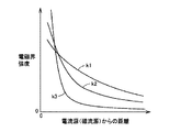
図3は、電流源(磁流源)からの距離と電磁界の強度との関係を示した図である。図3を参照して、電磁界は3つの成分から成る。曲線k1は、波源からの距離に反比例した成分であり、「輻射電磁界」と称される。曲線k2は、波源からの距離の2乗に反比例した成分であり、「誘導電磁界」と称される。また、曲線k3は、波源からの距離の3乗に反比例した成分であり、「静電磁界」と称される。 FIG. 3 is a diagram showing the relationship between the distance from the current source (magnetic current source) and the intensity of the electromagnetic field. Referring to FIG. 3, the electromagnetic field is composed of three components. The curve k1 is a component that is inversely proportional to the distance from the wave source, and is referred to as a “radiated electromagnetic field”. A curve k2 is a component inversely proportional to the square of the distance from the wave source, and is referred to as an “induction electromagnetic field”. The curve k3 is a component inversely proportional to the cube of the distance from the wave source, and is referred to as an “electrostatic magnetic field”.
「静電磁界」は、波源からの距離とともに急激に電磁界の強度が減少する領域であり、共鳴法では、この「静電磁界」が支配的な近接場(エバネッセント場)を利用してエネルギー(電力)の伝送が行なわれる。すなわち、「静電磁界」が支配的な近接場において、同じ固有振動数を有する一対の共鳴器(たとえば一対のLC共振コイル)を共鳴させることにより、一方の共鳴器(一次共振コイル)から他方の共鳴器(二次共振コイル)へエネルギー(電力)を伝送する。この「静電磁界」は遠方にエネルギーを伝播しないので、遠方までエネルギーを伝播する「輻射電磁界」によってエネルギー(電力)を伝送する電磁界に比べて、共鳴法は、より少ないエネルギー損失で送電することができる。 The “electrostatic magnetic field” is a region where the strength of the electromagnetic field suddenly decreases with the distance from the wave source. In the resonance method, energy is obtained by utilizing the near field (evanescent field) in which this “electrostatic magnetic field” is dominant. (Power) is transmitted. That is, by resonating a pair of resonators having the same natural frequency (for example, a pair of LC resonance coils) in a near field where “electrostatic magnetic field” is dominant, one resonator (primary resonance coil) is resonated with the other. Energy (electric power) is transmitted to the resonator (secondary resonance coil). Since this "electrostatic magnetic field" does not propagate energy far away, the resonance method transmits power with less energy loss compared to an electromagnetic field that transmits energy (electric power) by a "radiant electromagnetic field" that propagates energy far away. can do.
図4は、本実施の形態におけるコイルユニット400の一例の概略図が示される。図4を参照して、コイルユニット400は、電磁誘導コイル410と、共振コイル420と、ボビン430と、キャパシタ440とを含む。
FIG. 4 shows a schematic diagram of an example of the
電磁誘導コイル410は、図1における、一次電磁誘導コイル230および二次電磁誘導コイル120に対応する。また、共振コイル420は、図1における、一次共振コイル240および二次共振コイル110に対応する。
The
電磁誘導コイル410は、コイル材が円筒状で絶縁性のボビン430周囲に巻回される。そして、共振コイル420と同軸上に配置される。電磁誘導コイル410の両端は、コイルユニット400を収納するコイルケース(図示しない)の外部に引き出されて外部電源もしくは負荷に接続される。そして、電磁誘導コイル410は、電磁誘導により、共振コイル420と電力の送電または受電を行なう。
The
共振コイル420は、ボビン430周囲にコイル材が巻回されるように装着される。そして、共振コイル420のコイル両端は、ボビン430の内部に設置されたキャパシタ440に接続されることにより、LC共振回路を構成する。なお、キャパシタ440は必ずしも必要ではなく、共振コイル420の寄生容量により所望の容量成分が実現される場合には、共振コイル420の両端は非接続(オープン)とされる。
The
そして、共振コイル420は、対向する他の共振コイルと電磁共鳴することにより電力を転送する。また、共振コイル420は、電磁誘導によって、電磁誘導コイル410との電力を受け渡しが行なわれる。
The
上述のように、共鳴法を用いた電力伝達は、電磁誘導を用いた場合と比べて大きな電力(たとえば、数kW)を非接触でより遠方に伝達することができる。しかしながら、共振コイルにはこのような大電力が発生するため、共振コイルの発熱等に起因するシステム故障が発生するおそれがある。そのため、このような故障の防止のために、共振コイルの異常検出をすることが必要とされる。 As described above, the power transmission using the resonance method can transmit a large amount of power (for example, several kW) more distantly without contact compared to the case of using electromagnetic induction. However, since such a large power is generated in the resonance coil, there is a possibility that a system failure due to heat generation of the resonance coil may occur. Therefore, in order to prevent such a failure, it is necessary to detect abnormality of the resonance coil.
一般的に、コイルの温度を検出する場合、たとえば、サーミスタや熱電対などのような接触式の温度センサを用いて直接コイルの温度を検出する方法が採用される場合がある。しかしながら、共鳴法においては、このような温度センサを共振コイルに接触させて、または共振コイルの近傍に配置すると、共振コイルと温度センサ間との寄生容量によって共振コイルの共鳴周波数が変わってしまったり、この寄生容量によって温度センサに電流が流れることによりQ値を悪化させてしまったりするなど、共鳴状態に影響をおよぼすおそれがある。 Generally, when detecting the temperature of a coil, the method of detecting the temperature of a coil directly using a contact-type temperature sensor like a thermistor, a thermocouple, etc. may be employ | adopted, for example. However, in the resonance method, when such a temperature sensor is placed in contact with or near the resonance coil, the resonance frequency of the resonance coil changes due to the parasitic capacitance between the resonance coil and the temperature sensor. The parasitic capacitance may affect the resonance state, for example, the current value may flow through the temperature sensor to deteriorate the Q value.
また、光ファイバやレーザを用いた非接触式の温度センサも一般的に知られており、このような温度センサを採用することも可能である。しかしながら、これらのセンサは比較的高価であるので、コストアップにつながる可能性がある。 Further, a non-contact temperature sensor using an optical fiber or a laser is generally known, and such a temperature sensor can be employed. However, these sensors are relatively expensive and may lead to increased costs.
そのため、本実施の形態においては、共鳴状態への影響の少ない電圧検出器を用いて共振コイルにかかる電圧を検出し、その検出電圧に基づいて共振コイルの異常を判定する手法を採用する。以下、詳細について説明する。 Therefore, in the present embodiment, a method is adopted in which a voltage applied to the resonance coil is detected using a voltage detector that has little influence on the resonance state, and abnormality of the resonance coil is determined based on the detected voltage. Details will be described below.
図5は、本実施の形態における共振コイルの異常検出のための概要を説明するための図である。なお、図1と重複する要素の説明は繰り返さない。 FIG. 5 is a diagram for explaining an outline for detecting abnormality of the resonance coil in the present embodiment. Note that description of elements overlapping with those in FIG. 1 will not be repeated.
図5を参照して、図1の交流電源210および高周波電力ドライバ220に対応する高周波電源205は一次電磁誘導コイル230に接続される。
Referring to FIG. 5, high
一次共振コイル240の両端には、共振周波数を調整するためのキャパシタ245が必要に応じて接続される。
電圧検出器250は、キャパシタ245の両端に接続され、キャパシタ245にかかる電圧、すなわち一次共振コイル240にかかる電圧を検出する。そして、電圧検出器250は、一次共振コイル240にかかる電圧に関連する信号VC1を送電ECU260へ出力する。
The
送電ECU260は、上述の信号VC1と基準電圧とを比較することによって、後述するように一次共振コイル240の温度が許容温度より大きくなっているか否かを判定する。また、送電ECU260は、上記の信号VC1と、高周波電源205により供給される送電電圧に関連する信号VSとを比較することによって、一次共振コイル240と二次共振コイル110との間のQ値が低下しているか否かを判定する。そして、送電ECU260は、これらの異常の少なくともいずれか一方が発生していると判断した場合は、異常信号ALM1を警告装置270へ出力して操作者へ異常の発生を通知する。
The
一方、車両100側の二次共振コイル110の両端には、共振周波数を調整するためのキャパシタ115が必要に応じて接続される。
On the other hand, a
電圧検出器190は、キャパシタ115の両端に接続され、キャパシタ115にかかる電圧、すなわち二次共振コイル110にかかる電圧を検出する。そして、電圧検出器190は、二次共振コイル110にかかる電圧に関連する信号VC2を車両ECU180へ出力する。
The
車両ECU180は、上述の信号VC2と基準電圧とを比較することによって、二次共振コイル110の温度が許容温度より大きくなっているか否かを判定する。また、車両ECU180は、上記の信号VC2と、送電ECU260から伝送される送電電圧に関連する信号VSとを比較することによって、一次共振コイル240と二次共振コイル110との間のQ値が低下しているか否かを判定する。そして、車両ECU180は、これらの異常の少なくともいずれか一方が発生していると判断した場合は、異常信号ALM2を警告装置195へ出力して操作者へ異常の発生を通知する。
The
次に、電圧検出器190,250の詳細な構成について説明する。
図6は、本実施の形態に従う電圧検出器190,250の概略図である。なお、図6においては、車両100側の電圧検出器190を例として説明するが、給電装置200側の電圧検出器250についても、基本的な構成は以下の電圧検出器190の説明と同様であるため、その説明は繰り返さない。
Next, the detailed configuration of the
FIG. 6 is a schematic diagram of
図5および図6を参照して、電圧検出器190は、キャパシタ510,520と、絶縁トランス550と、出力端子の一例である同軸コネクタ560と、絶縁トランス550を収納するシールドケース540とを備える。
Referring to FIGS. 5 and 6,
キャパシタ510,520の各一方端は、二次共振コイル110の両端にそれぞれ接続される。二次共振コイル110が、図5のように、共鳴周波数の調整用のキャパシタ115に接続されている場合には、キャパシタ510,520は、キャパシタ115の両端にそれぞれ接続される。また、キャパシタ510,520の各他方端は、絶縁トランス550の一次側(入力側)に接続される。
One end of each of
キャパシタ510は、二次共振コイル110と接続するための電極511と、絶縁トランス550と接続するための電極512と、電極511,512の間に設けられた誘電体513とを含む。キャパシタ520も同様に、二次共振コイル110と接続するための電極521と、絶縁トランス550と接続するための電極522と、電極521,522の間に設けられた誘電体523とを含む。
キャパシタ510,520は、二次共振コイル110に発生する高電圧を分圧し、絶縁トランス550にかかる電圧を低減するためのアッテネータとして機能する。そのため、キャパシタ510,520の静電容量は、絶縁トランス550の耐電圧を低減するとともに電圧変化が検出できる程度の電圧になる範囲で、十分小さくする(すなわち、高インピーダンスとする)ことが好適である。
なお、絶縁トランス550全体のインピーダンスは、キャパシタ510,520のインピーダンスと比較して小さく設定されるが、キャパシタ510,520のインピーダンスに対する絶縁トランス550全体のインピーダンスは、出力端子である同軸コネクタ560に接続される後続の電子回路のために必要とされる減衰比に基づいて設定される。
Note that the impedance of the
また、キャパシタ510,520は、誘電体513,523の電界方向の長さ(すなわち、電極間の距離)が、各電極の幅(すなわち、電極の上記の電界方向に垂直な長さ)よりも長くなるように形成されることが好ましい。言い換えれば、各電極の面積が小さく、誘電体の長さが長い、細長い形状とされることが好ましい。これは、電圧検出器190の絶縁トランス550と、二次共振コイル110との間の距離をできるだけ大きくすることで、キャパシタ510,520が二次共振コイル110に接続されることによって、キャパシタ510,520および絶縁トランス550の接続点とシールドボックス540間に発生する寄生容量、ならびに、二次共振コイル110の両端とシールドボックス540との間に発生する寄生容量をできるだけ小さく(すなわち、インピーダンスを高く)し、二次共振コイル110のQ値への影響を低減するためである。さらに、誘電体513,523の表面に沿って放電する沿面放電を防止する効果もある。
Further, in the
キャパシタ510,520の絶縁トランス550側の電極512,522は、端子板530に固定される。端子板530は、絶縁体であり、後述する、絶縁トランス550を収納するシールドケース540の一部を形成する。あるいは、端子板530は、二次共振コイル110からの電磁場の影響を抑制するために電磁遮蔽材とすることもできるが、その場合は、電極512,522間の短絡を防止するために、高抵抗率かつ高透磁率を有する材料とすることが好適である。
絶縁トランス550は、一次コイル551と、二次コイル552と、トロイダルコア553とを含む。
一次コイル551は、トロイダルコア553に巻回されるとともに、その両端がキャパシタ510,520の電極512,522にそれぞれ接続される。二次コイル552は、トロイダルコア553に巻回されるとともに、その両端が、シールドケース540に固定された出力端子である同軸コネクタ560の各端子にそれぞれ接続される。このような構成とすることによって、同軸コネクタ560と、二次共振コイル110とが電気的に絶縁される。また、必要に応じて一次コイル551と二次コイル552との巻数比を変更することによって、一次コイル551に入力される入力電圧を所望の電圧に変換するようにしてもよい。
なお、電圧検出器190を構成する各要素は、図6のように、二次共振コイル110に接続される電極511,521に対して、寄生容量が対称となるように配置されることが好ましい。すなわち、キャパシタ510,520および絶縁トランス550の接続点とシールドボックス540間に発生する寄生容量が対称となるとともに、二次共振コイル110の両端とシールドボックス540との間に発生する寄生容量が対称となるように各要素が配置される。このようにすることによって、平衡した差動電圧を出力することが可能となるので、車両ECU180における処理を簡素化できるという効果が得られる。そのため、キャパシタ510,520の静電容量は、ほぼ等しい容量値に設計することが好ましい。
Note that each element constituting the
また、電圧検出器190を構成する各要素は、二次共振コイル110から発生する電磁場の影響を抑制するために、シールドケース540内に収納される。
Further, each element constituting the
同軸コネクタ560は、同軸ケーブル(図示せず)によって車両ECU180と接続され、二次コイル552で検出された、二次共振コイル110にかかる電圧に関する信号を車両ECU180へ出力する。
なお、電圧検出器190としては、二次共振コイル110にかかる電圧を分圧する機能(キャパシタ510,520に相当)と、二次共振コイル110と車両ECU180とを電気的に絶縁する機能(絶縁トランスに相当)を有する構成であれば、基本的にはどのような構成であってもよい。
The
たとえば、キャパシタ510,520に代えて、高抵抗で長さの長いケーブルを用いることによって分圧することも可能である。しかしながら、このような構成の場合、二次共振コイル110に直列に接続された抵抗成分の増加やインダクタンスの増加、さらに長いケーブルによってケーブルと二次共振コイル110との間の寄生容量の増加によって、二次共振コイル110の共鳴状態に影響をおよぼしたり、抵抗成分による発熱に対する対策のために検出器の体格を大きくすることが必要となったりする可能性がある。また、降圧比の大きいトランスを直接二次共振コイル110に接続する構成も考えられるが、このような場合には、電圧検出回路全体の入力インピーダンスを下げにくいため、トランスの巻線間での部分放電の発生を抑制する場合があり、これらへの対策等が別途必要となるおそれがある。
For example, instead of the
そのため、図6で説明したような電圧検出器の構成とすることによって、電圧の測定対象である共振コイルの共鳴状態への影響を低減することができる。また、キャパシタを用いることによって、発熱を抑制しつつ電圧を低下させることができるので、電圧検出器自体の小型化を実現してコストアップを抑制することが可能となる。また、電圧検出回路の寄生容量が低減されるので、電圧検出回路のコモンモードノイズおよびノーマルモードノイズを低減することが可能になる。 Therefore, the configuration of the voltage detector as described with reference to FIG. 6 can reduce the influence on the resonance state of the resonance coil that is the voltage measurement target. In addition, since the voltage can be reduced while suppressing heat generation by using the capacitor, it is possible to reduce the size of the voltage detector itself and suppress an increase in cost. In addition, since the parasitic capacitance of the voltage detection circuit is reduced, common mode noise and normal mode noise of the voltage detection circuit can be reduced.
次に、この電圧検出器を用いた共振コイルの異常検出について説明する。
図7は、本実施の形態における共振コイルの異常検出制御を説明するための機能ブロック図である。図7で説明される機能ブロック図に記載された各機能ブロックは、車両ECU180および送電ECU260において、ハードウェア的あるいはソフトウェア的な処理によって実現される。なお、図7および以降で説明する図8,図9においては、車両100側の車両ECU180における制御を例として説明するが、給電装置200側の送電ECU260についても基本的には同様の構成とすることが可能であり、その説明は繰り返さない。
Next, abnormality detection of the resonance coil using this voltage detector will be described.
FIG. 7 is a functional block diagram for explaining abnormality detection control of the resonance coil in the present embodiment. Each functional block described in the functional block diagram illustrated in FIG. 7 is realized by hardware or software processing in
図5および図7を参照して、車両ECU180は、電圧検出部600と、基準電圧設定部610と、異常判定部620と、警報出力部630と、指令生成部640とを含む。
Referring to FIGS. 5 and 7,
電圧検出部600は、電圧検出器190によって検出された二次共振コイル110にかかる電圧に対応する電圧を示す信号VC2(交流信号)、および、給電装置200から受けた給電装置200からの送電電圧に関する信号VS(交流信号)を受ける。電圧検出部600は、これらの信号を整流するとともに必要に応じてゲインを調整して電圧信号VC2d,VSd(直流信号)を生成し、異常判定部620へ出力する。
The
基準電圧設定部610は、温度センサ196で検出された外気温TMPを受ける。そして、基準電圧設定部610は、この外気温TMPに基づいて、二次共振コイル110に許容される基準電圧Vrefを設定し、異常判定部620へ出力する。
Reference
ここで、基準電圧設定部610における基準電圧Vrefの設定についての概要を説明する。一般的に、共振コイルの発熱は、共振コイルの抵抗成分と共振コイルに流れる電流の二乗に比例し、この共振コイルに流れる電流は共振コイルにかかる電圧に比例する。そして、共振コイルの温度の定常値は、周囲温度(すなわち外気温)と共振コイルの発熱による温度上昇に基づいて推定できる。そして、たとえば外気温が高い場合には、外気温が低い場合に比べて、コイルの許容温度までの温度上昇量を小さく抑えることが必要となる。そのため、たとえば、予め実験等によって定められた、二次共振コイルにかかる電圧とそのときの二次共振コイルの温度との関係を示すマップなどを用いて、現在の外気温において許容される共振コイルの発熱量に相当する基準電圧Vrefを設定することができる。
Here, an outline of setting the reference voltage Vref in the reference
異常判定部620は、電圧検出部600からの直流電圧VC2d,VSdおよび基準電圧設定部610からの基準電圧Vrefの入力を受ける。
異常判定部620は、電圧VC2dと基準電圧Vrefとを比較する。異常判定部620は、電圧VC2dが基準電圧Vrefより大きい場合は、二次共振コイル110が許容温度以上となっていると判断する。そして、異常判定部620は、共振コイルが高温になっていることを示す高温信号HTMPを生成して、警報出力部630および指令生成部640へ出力する。基準電圧設定部610で設定される基準電圧Vrefは、上述のような二次共振コイル110の許容温度による設定に限られず、それに代えて、あるいは、それに加えて共鳴用キャパシタ115の耐電圧や二次共振コイル110の絶縁耐圧などを検出するための他の基準電圧を設定するようにしてもよい。なお、この異常検出の手法においては、共振コイルの電圧が低下するような異常については検出することは困難である。
さらに、異常判定部620は、電圧VC2dと電圧VSdとを比較する。異常判定部620は、電圧VC2dが電圧VSdより小さい場合は、二次共振コイル110とキャパシタ115とで構成される共振回路の絶縁不良や、共振回路以外の他の機器等(または、誘電体や磁性体など)の接近などに起因してQ値が低下している、すなわち共振回路による損失が増加していると判断する。そして、異常判定部620は、Q値が低下したことを示すQ値低下信号LQを生成して、警報出力部630および指令生成部640へ出力する。
Furthermore,
警報出力部630は、高温信号HTMP、Q値低下信号LQなどの異常を示す信号を異常判定部620から受ける。そして、警報出力部630は、異常が発生している場合には、警告装置195へ警告信号ALM2を出力することによって、操作者に対して異常の発生を通知する。
The
指令生成部640は、高温信号HTMP、Q値低下信号LQなどの異常を示す信号を異常判定部620から受ける。そして、異常の状態に応じて、給電装置200に対して、給電装置200からの給電電力の変更(増加または減少)や給電停止を指示したり、または、車両100のDC/DCコンバータ140を停止させたりするための制御信号CRLを生成し、給電装置200およびDC/DCコンバータ140などに出力する。
図8は、図7で説明した機能ブロック図における、電圧検出部600および異常判定部620をアナログ回路で構成した一例を示す図である。
FIG. 8 is a diagram illustrating an example in which the
図7および図8を参照して、車両ECU180は、整流回路710,720と、ゲイン調整部730と、比較器740,750とを含む。この中で、整流回路710,720およびゲイン調整部730が図7における電圧検出部600の一例であり、比較器740,750が図7における異常判定部620の一例である。
Referring to FIGS. 7 and 8,
整流回路710は、電圧検出器190からの受ける交流信号である電圧VC2を直流信号のVC2dに整流する。そして、整流回路710は、信号VC2dを比較器740,750の正側の入力端子へ出力する。
The
比較器740は、整流回路710で整流された信号VC2dと、比較器740の負側の入力端子に入力される基準電圧Vrefとを比較し、信号VC2dが基準電圧Vrefより大きい場合は、高温信号HTMPを警報出力部630および指令生成部640へ出力する。
The
整流回路720は、送電ECU260から伝送された交流信号である電圧VSを直流信号のVSd*に整流する。ゲイン調整部730は、整流回路720からの直流信号VSd*に所定のゲインを乗じて信号VSdを生成し、比較器750の負側の入力端子に出力する。
The
比較器750は、整流回路710で整流された信号VC2dと、ゲイン調整部730からの信号VSdとを比較し、信号VC2dが信号VSdよりも小さい場合は、Q値低下信号LQを警報出力部630および指令生成部640へ出力する。
The
なお、図8の回路は、アナログ回路で構成した例を説明したが、上記の機能の少なくとも一部をデジタル信号処理(ハードウェア、ソフトウェアを含む)によって実現するようにしてもよい。 Although the circuit of FIG. 8 has been described as an example of an analog circuit, at least a part of the above functions may be realized by digital signal processing (including hardware and software).
図9は、本実施の形態における共振コイルの異常検出制御処理の詳細を説明するためのフローチャートである。図9に示されるフローチャート中の各ステップについては、車両ECU180に予め格納されたプログラムを所定周期でメインプログラムから呼び出して実行することによって実現される。あるいは、一部のステップについては、専用のハードウェア(電子回路)を構築して処理を実現することも可能である。
FIG. 9 is a flowchart for explaining details of the abnormality detection control process for the resonance coil in the present embodiment. Each step in the flowchart shown in FIG. 9 is realized by calling and executing a program stored in advance in
図9を参照して、車両ECU180は、ステップ(以下、ステップをSと略す。)100において、二次共振コイル110の電圧に関する信号VC2および給電装置200からの送電電圧に関する信号VSと、外気温TMPを取得する。そして、車両ECU180は、交流信号の信号VC2,VSから直流信号の信号VC2d,VSdをそれぞれ算出する。
Referring to FIG. 9,
次に、車両ECU180は、S110にて、外気温TMPに基づいて、基準電圧Vrefを演算する。そして、車両ECU180は、S120にて信号VC2dが基準電圧Vrefより大きいか否かを判定する。
Next,
信号VC2dが基準電圧Vrefより大きい場合(S120にてYES)は、ECU180は、S130に処理を進めて、二次共振コイル110の高温異常が発生していると判定する。そして、車両ECU180は、S140にて、コイル高温異常に対応した異常処理を行なう。具体的には、給電装置200に対して指令を出力して、給電電力を低下または停止させたり、DC/DCコンバータ140を停止させて受電動作を停止したりする。あるいは、二次共振コイル110を冷却するための冷却装置(図示せず)を有する場合には、冷却装置を作動させながら給電動作を継続するようにしてもよい。
If signal VC2d is greater than reference voltage Vref (YES in S120),
そして、車両ECU180は、S150にて、アラームを出力して、コイル高温異常が発生していることを操作者に通知し、S160に処理を進める。
Then,
一方、信号VC2dが基準電圧Vref以下の場合(S120にてNO)は、車両ECU180は、二次共振コイル110は高温となっていないと判定し、S130〜S150の処理をスキップして、S160に処理を進める。
On the other hand, when signal VC2d is equal to or lower than reference voltage Vref (NO in S120),
S160では、車両ECU180は、信号VC2dが信号VSdより大きいか否かを判定する。
In S160,
信号VC2dが信号VSdより小さい場合(S160にてYES)は、ECU180は、S170に処理を進めて、Q値の低下異常が発生していると判定する。そして、車両ECU180は、S180にて、Q値低下異常に対応した異常処理を行なう。具体的には、給電装置200に対して指令を出力して、所望の電力を供給するために給電電力を増加したり、あるいは他の機器等への影響を抑制するために給電を停止したりする。
If signal VC2d is smaller than signal VSd (YES in S160),
そして、車両ECU180は、S190にて、アラームを出力して、Q値低下異常が発生していることを操作者に通知する。
Then,
一方、信号VC2dが信号VSd以上の場合(S160にてNO)は、車両ECU180は、Q値低下が発生していないと判定し、S170〜S190の処理をスキップして、メインルーチンの処理を戻す。
On the other hand, when signal VC2d is equal to or higher than signal VSd (NO in S160),
上述のような構成を有する電圧検出器を用い、以上のような処理に従って制御することによって、共鳴法を用いた非接触給電システムにおいて、共振コイルの共鳴状態への影響およびコストアップを抑制しつつ、共振コイルの異常を検出することができる。 By using the voltage detector having the above-described configuration and controlling according to the processing as described above, in the non-contact power feeding system using the resonance method, the influence on the resonance state of the resonance coil and the cost increase are suppressed. The abnormality of the resonance coil can be detected.
なお、本実施の形態における「キャパシタ510,520」は、それぞれ本発明の「第1の高インピーダンス要素」および「第2の高インピーダンス要素」の一例である。本実施の形態の「絶縁トランス550」は、本発明の「低インピーダンス要素」の一例である。
The “
今回開示された実施の形態はすべての点で例示であって制限的なものではないと考えられるべきである。本発明の範囲は上記した説明ではなくて特許請求の範囲によって示され、特許請求の範囲と均等の意味および範囲内でのすべての変更が含まれることが意図される。 The embodiment disclosed this time should be considered as illustrative in all points and not restrictive. The scope of the present invention is defined by the terms of the claims, rather than the description above, and is intended to include any modifications within the scope and meaning equivalent to the terms of the claims.
100 車両、110,340 二次共振コイル、115,245,440,510,520 キャパシタ、120,350 二次電磁誘導コイル、130 整流器、140 DC/DCコンバータ、150 蓄電装置、160 PCU、170 モータ、180 車両ECU、190,250 電圧検出器、195,270 警告装置、196,280 温度センサ、200 給電装置、205,310 高周波電源、210 交流電源、220 高周波電力ドライバ、230,320 一次電磁誘導コイル、240,330 一次共振コイル、260 送電ECU、360 負荷、400 コイルユニット、410 電磁誘導コイル、420 共振コイル、430 ボビン、511,512,521,522 電極、513,523 誘電体、530 端子板、540 シールドケース、550 絶縁トランス、551 一次コイル、552 二次コイル、553 トロイダルコア、560 同軸コネクタ、600 電圧検出部、610 基準電圧設定部、620 異常判定部、630 警報出力部、640 指令生成部、710,720 整流回路、730 ゲイン調整部、740,750 比較器。
100 vehicle, 110, 340 secondary resonance coil, 115, 245, 440, 510, 520 capacitor, 120, 350 secondary electromagnetic induction coil, 130 rectifier, 140 DC / DC converter, 150 power storage device, 160 PCU, 170 motor, 180 vehicle ECU, 190,250 voltage detector, 195,270 warning device, 196,280 temperature sensor, 200 power supply device, 205,310 high frequency power source, 210 AC power source, 220 high frequency power driver, 230,320 primary electromagnetic induction coil, 240, 330 Primary resonance coil, 260 Power transmission ECU, 360 Load, 400 Coil unit, 410 Electromagnetic induction coil, 420 Resonance coil, 430 Bobbin, 511, 512, 521, 522 Electrode, 513, 523 Dielectric, 530
Claims (17)
前記第2の共振コイルの一方端に、その一方端が接続される第1の高インピーダンス要素と、
前記第2の共振コイルの他方端に、その一方端が接続される第2の高インピーダンス要素と、
前記第1の高インピーダンス要素の他方端と、前記第2の高インピーダンス要素の他方端との間に接続され、前記第1および第2の高インピーダンス要素の各々よりもインピーダンスが小さい、低インピーダンス要素と、
前記低インピーダンス要素の両端にかかる電圧に関連する信号を出力するための出力端子とを備え、
前記第1の高インピーダンス要素は、第1のキャパシタを含み、
前記第2の高インピーダンス要素は、第2のキャパシタを含む、電圧検出器。 A voltage detector for detecting a voltage generated in a first resonance coil arranged oppositely and a second resonance coil that performs at least one of power transmission and reception in a non-contact manner by electromagnetic resonance,
A first high impedance element having one end connected to one end of the second resonant coil;
A second high impedance element having one end connected to the other end of the second resonant coil;
A low-impedance element connected between the other end of the first high-impedance element and the other end of the second high-impedance element, having a smaller impedance than each of the first and second high-impedance elements When,
An output terminal for outputting a signal related to a voltage applied to both ends of the low impedance element ;
The first high impedance element includes a first capacitor;
The voltage detector, wherein the second high impedance element includes a second capacitor .
前記第2の共振コイルと接続するための電極と、
電界方向の長さが、前記電界方向と垂直な方向の前記電極の長さよりも大きい誘電体とを含む、請求項1に記載の電圧検出器。 Each of the first and second capacitors includes:
An electrode for connecting to the second resonance coil;
The voltage detector according to claim 1 , further comprising a dielectric having a length in an electric field direction larger than a length of the electrode in a direction perpendicular to the electric field direction.
前記絶縁トランスは、
前記第1および第2の高インピーダンス要素の各々の他方端の間に接続される1次コイルと、
前記出力端子に接続される2次コイルと、
前記1次コイルおよび前記2次コイルが巻回されるトロイダルコアとを含む、請求項1に記載の電圧検出器。 The low impedance element is an isolation transformer;
The insulating transformer is
A primary coil connected between the other ends of each of the first and second high impedance elements;
A secondary coil connected to the output terminal;
The voltage detector according to claim 1, comprising a toroidal core around which the primary coil and the secondary coil are wound.
前記絶縁トランスは、前記シールドボックス内に配置される、請求項5に記載の電圧検出器。 A shield box for shielding an electromagnetic field generated from the second resonance coil;
The voltage detector according to claim 5 , wherein the isolation transformer is disposed in the shield box.
前記第2の共振コイルに接続するための電極を含み、
前記第1および第2の高インピーダンス要素、ならびに前記低インピーダンス要素は、前記電極の各々に対して接続されるインピーダンスが対称となるように配置される、請求項1に記載の電圧検出器。 Each of the first and second high impedance elements comprises:
An electrode for connecting to the second resonant coil;
The voltage detector according to claim 1, wherein the first and second high impedance elements and the low impedance element are arranged such that impedances connected to each of the electrodes are symmetrical.
前記電圧検出器から出力される電圧に関連する信号に基づいて、前記第2の共振コイルの異常を判定するように構成された異常判定部とを備える、異常検出装置。 The voltage detector according to any one of claims 1 to 7 ,
An abnormality detection device comprising: an abnormality determination unit configured to determine abnormality of the second resonance coil based on a signal related to a voltage output from the voltage detector.
前記受電装置と電磁共鳴を行なうための共振コイルと、
電磁誘導によって、前記電源からの電力を前記共振コイルに伝達するように構成された電磁誘導コイルと、
前記共振コイルに発生する電圧を検出するための電圧検出器と、
前記電圧検出器から出力される電圧に関連する信号に基づいて、前記共振コイルの異常を検出するように構成された異常判定部とを備え、
前記電圧検出器は、
前記共振コイルの一方端に、その一方端が接続される第1の高インピーダンス要素と、
前記共振コイルの他方端に、その一方端が接続される第2の高インピーダンス要素と、
前記第1の高インピーダンス要素の他方端と、前記第2の高インピーダンス要素の他方端との間に接続され、前記第1および第2の高インピーダンス要素の各々よりもインピーダンスが小さい、低インピーダンス要素と、
前記低インピーダンス要素の両端にかかる電圧に関連する信号を出力するための出力端子とを含み、
前記第1の高インピーダンス要素は、第1のキャパシタを有し、
前記第2の高インピーダンス要素は、第2のキャパシタを有する、非接触送電装置。 A non-contact power transmission device for non-contact transmission of power from a power source to a power receiving device by electromagnetic resonance,
A resonance coil for performing electromagnetic resonance with the power receiving device;
An electromagnetic induction coil configured to transmit power from the power source to the resonant coil by electromagnetic induction;
A voltage detector for detecting a voltage generated in the resonance coil;
An abnormality determination unit configured to detect an abnormality of the resonance coil based on a signal related to the voltage output from the voltage detector;
The voltage detector is
A first high impedance element having one end connected to one end of the resonant coil;
A second high impedance element having one end connected to the other end of the resonant coil;
A low-impedance element connected between the other end of the first high-impedance element and the other end of the second high-impedance element, having a smaller impedance than each of the first and second high-impedance elements When,
Look including an output terminal for outputting a signal related to the voltage across the low impedance element,
The first high impedance element has a first capacitor;
The non-contact power transmission device , wherein the second high impedance element includes a second capacitor .
前記送電装置と電磁共鳴を行なうための共振コイルと、
電磁誘導によって、前記共振コイルで受電した電力を取出すように構成された電磁誘導コイルと、
前記共振コイルに発生する電圧を検出するための電圧検出器と、
前記電圧検出器から出力される電圧に関連する信号に基づいて、前記共振コイルの異常を検出するように構成された異常判定部とを備え、
前記電圧検出器は、
前記共振コイルの一方端に、その一方端が接続される第1の高インピーダンス要素と、
前記共振コイルの他方端に、その一方端が接続される第2の高インピーダンス要素と、
前記第1の高インピーダンス要素の他方端と、前記第2の高インピーダンス要素の他方端との間に接続され、前記第1および第2の高インピーダンス要素の各々よりもインピーダンスが小さい、低インピーダンス要素と、
前記低インピーダンス要素の両端にかかる電圧に関連する信号を出力するための出力端子とを含み、
前記第1の高インピーダンス要素は、第1のキャパシタを有し、
前記第2の高インピーダンス要素は、第2のキャパシタを有する、非接触受電装置。 A non-contact power receiving device for receiving power from a power transmitting device in a non-contact manner by electromagnetic resonance,
A resonance coil for performing electromagnetic resonance with the power transmission device;
An electromagnetic induction coil configured to extract electric power received by the resonance coil by electromagnetic induction; and
A voltage detector for detecting a voltage generated in the resonance coil;
An abnormality determination unit configured to detect an abnormality of the resonance coil based on a signal related to the voltage output from the voltage detector;
The voltage detector is
A first high impedance element having one end connected to one end of the resonant coil;
A second high impedance element having one end connected to the other end of the resonant coil;
A low-impedance element connected between the other end of the first high-impedance element and the other end of the second high-impedance element, having a smaller impedance than each of the first and second high-impedance elements When,
Look including an output terminal for outputting a signal related to the voltage across the low impedance element,
The first high impedance element has a first capacitor;
The non-contact power receiving device , wherein the second high impedance element includes a second capacitor .
前記電源からの電力を供給する送電装置と、
前記送電装置と対向する受電装置とを備え、
前記送電装置は、
前記受電装置と電磁共鳴を行なうための共振コイルと、
電磁誘導によって、前記電源からの電力を前記共振コイルに伝達するように構成された電磁誘導コイルと、
前記共振コイルに発生する電圧を検出するための電圧検出器と、
前記電圧検出器から出力される電圧に関連する信号に基づいて、前記共振コイルの異常を検出するように構成された異常判定部とを備え、
前記電圧検出器は、
前記共振コイルの一方端に、その一方端が接続される第1の高インピーダンス要素と、
前記共振コイルの他方端に、その一方端が接続される第2の高インピーダンス要素と、
前記第1の高インピーダンス要素の他方端と、前記第2の高インピーダンス要素の他方端との間に接続され、前記第1および第2の高インピーダンス要素の各々よりもインピーダンスが小さい、低インピーダンス要素と、
前記低インピーダンス要素の両端にかかる電圧に関連する信号を出力するための出力端子とを含み、
前記第1の高インピーダンス要素は、第1のキャパシタを有し、
前記第2の高インピーダンス要素は、第2のキャパシタを有する、非接触給電システム。 A non-contact power feeding system for non-contact transmission of power from a power source by electromagnetic resonance,
A power transmission device for supplying power from the power source;
A power receiving device facing the power transmitting device,
The power transmission device is:
A resonance coil for performing electromagnetic resonance with the power receiving device;
An electromagnetic induction coil configured to transmit power from the power source to the resonant coil by electromagnetic induction;
A voltage detector for detecting a voltage generated in the resonance coil;
An abnormality determination unit configured to detect an abnormality of the resonance coil based on a signal related to the voltage output from the voltage detector;
The voltage detector is
A first high impedance element having one end connected to one end of the resonant coil;
A second high impedance element having one end connected to the other end of the resonant coil;
A low-impedance element connected between the other end of the first high-impedance element and the other end of the second high-impedance element, having a smaller impedance than each of the first and second high-impedance elements When,
Look including an output terminal for outputting a signal related to the voltage across the low impedance element,
The first high impedance element has a first capacitor;
The non-contact power feeding system , wherein the second high impedance element includes a second capacitor .
前記電源からの電力を供給する送電装置と、
前記送電装置と対向する受電装置とを備え、
前記受電装置は、
前記送電装置と電磁共鳴を行なうための共振コイルと、
電磁誘導によって、前記共振コイルで受電した電力を取出すように構成された電磁誘導コイルと、
前記共振コイルに発生する電圧を検出するための電圧検出器と、
前記電圧検出器から出力される電圧に関連する信号に基づいて、前記共振コイルの異常を検出するように構成された異常判定部とを備え、
前記電圧検出器は、
前記共振コイルの一方端に、その一方端が接続される第1の高インピーダンス要素と、
前記共振コイルの他方端に、その一方端が接続される第2の高インピーダンス要素と、
前記第1の高インピーダンス要素の他方端と、前記第2の高インピーダンス要素の他方端との間に接続され、前記第1および第2の高インピーダンス要素の各々よりもインピーダンスが小さい、低インピーダンス要素と、
前記低インピーダンス要素の両端にかかる電圧に関連する信号を出力するための出力端子とを含み、
前記第1の高インピーダンス要素は、第1のキャパシタを有し、
前記第2の高インピーダンス要素は、第2のキャパシタを有する、非接触給電システム。 A non-contact power feeding system for non-contact transmission of power from a power source by electromagnetic resonance,
A power transmission device for supplying power from the power source;
A power receiving device facing the power transmitting device,
The power receiving device is:
A resonance coil for performing electromagnetic resonance with the power transmission device;
An electromagnetic induction coil configured to extract electric power received by the resonance coil by electromagnetic induction; and
A voltage detector for detecting a voltage generated in the resonance coil;
An abnormality determination unit configured to detect an abnormality of the resonance coil based on a signal related to the voltage output from the voltage detector;
The voltage detector is
A first high impedance element having one end connected to one end of the resonant coil;
A second high impedance element having one end connected to the other end of the resonant coil;
A low-impedance element connected between the other end of the first high-impedance element and the other end of the second high-impedance element, having a smaller impedance than each of the first and second high-impedance elements When,
Look including an output terminal for outputting a signal related to the voltage across the low impedance element,
The first high impedance element has a first capacitor;
The non-contact power feeding system , wherein the second high impedance element includes a second capacitor .
前記電源からの電力を供給する送電装置と、
前記送電装置と対向する受電装置とを備え、
前記送電装置は、
前記受電装置と電磁共鳴を行なうための第1の共振コイルと、
電磁誘導によって、前記電源からの電力を前記第1の共振コイルに伝達するように構成された第1の電磁誘導コイルと、
前記第1の共振コイルに発生する電圧を検出するための第1の電圧検出器と、
前記第1の電圧検出器から出力される電圧に関連する信号に基づいて、前記第1の共振コイルの異常を検出するように構成された第1の異常判定部とを含み、
前記第1の電圧検出器は、
前記第1の共振コイルの一方端に、その一方端が接続される第1の高インピーダンス要素と、
前記第1の共振コイルの他方端に、その一方端が接続される第2の高インピーダンス要素と、
前記第1の高インピーダンス要素の他方端と、前記第2の高インピーダンス要素の他方端との間に接続され、前記第1および第2の高インピーダンス要素の各々よりもインピーダンスが小さい、第1の低インピーダンス要素と、
前記第1の低インピーダンス要素の両端にかかる電圧に関連する信号を出力するための第1の出力端子とを含み、
前記第1の高インピーダンス要素は、第1のキャパシタを有し、
前記第2の高インピーダンス要素は、第2のキャパシタを有する、
前記受電装置は、
前記送電装置と電磁共鳴を行なうための第2の共振コイルと、
電磁誘導によって、前記第2の共振コイルで受電した電力を取出すように構成された第2の電磁誘導コイルと、
前記第2の共振コイルに発生する電圧を検出するための第2の電圧検出器と、
前記第2の電圧検出器から出力される電圧に関連する信号に基づいて、前記第2の共振コイルの異常を検出するように構成された第2の異常判定部とを含み、
前記第2の電圧検出器は、
前記第2の共振コイルの一方端に、その一方端が接続される第3の高インピーダンス要素と、
前記第2の共振コイルの他方端に、その一方端が接続される第4の高インピーダンス要素と、
前記第3の高インピーダンス要素の他方端と、前記第4の高インピーダンス要素の他方端との間に接続され、前記第3および第4の高インピーダンス要素の各々よりもインピーダンスが小さい、第2の低インピーダンス要素と、
前記第2の低インピーダンス要素の両端にかかる電圧に関連する信号を出力するための第2の出力端子とを含み、
前記第3の高インピーダンス要素は、第3のキャパシタを有し、
前記第4の高インピーダンス要素は、第4のキャパシタを有する、非接触給電システム。 A non-contact power feeding system for non-contact transmission of power from a power source by electromagnetic resonance,
A power transmission device for supplying power from the power source;
A power receiving device facing the power transmitting device,
The power transmission device is:
A first resonance coil for performing electromagnetic resonance with the power receiving device;
A first electromagnetic induction coil configured to transmit power from the power source to the first resonant coil by electromagnetic induction;
A first voltage detector for detecting a voltage generated in the first resonance coil;
A first abnormality determination unit configured to detect an abnormality of the first resonance coil based on a signal related to a voltage output from the first voltage detector;
The first voltage detector is
A first high impedance element having one end connected to one end of the first resonant coil;
A second high impedance element having one end connected to the other end of the first resonant coil;
And the other end of said first high-impedance element is connected between the front Symbol other end of the second high-impedance element, the impedance is less than each of said first and second high-impedance element, the first Low impedance elements of
A first output terminal for outputting a signal related to the voltage across the first low impedance element;
The first high impedance element has a first capacitor;
The second high impedance element includes a second capacitor;
The power receiving device is:
A second resonance coil for performing electromagnetic resonance with the power transmission device;
A second electromagnetic induction coil configured to extract power received by the second resonant coil by electromagnetic induction;
A second voltage detector for detecting a voltage generated in the second resonance coil;
A second abnormality determination unit configured to detect an abnormality of the second resonance coil based on a signal related to the voltage output from the second voltage detector,
The second voltage detector is
A third high impedance element having one end connected to one end of the second resonant coil;
A fourth high impedance element having one end connected to the other end of the second resonant coil;
A second impedance connected between the other end of the third high impedance element and the other end of the fourth high impedance element, and having a smaller impedance than each of the third and fourth high impedance elements; A low impedance element;
Look including a second output terminal for outputting a signal related to the voltage across the second low-impedance element,
The third high impedance element has a third capacitor;
The non-contact power feeding system , wherein the fourth high impedance element includes a fourth capacitor .
電磁共鳴によって送電装置からの電力を非接触で受電するための非接触受電装置と、
前記非接触受電装置によって受電された電力を用いて充電が可能な蓄電装置と、
前記蓄電装置からの電力を用いて前記車両を走行するための駆動力を発生するための駆動装置とを備え、
前記非接触受電装置は、
前記送電装置と電磁共鳴を行なうための共振コイルと、
電磁誘導によって、前記共振コイルで受電した電力を取出すように構成された電磁誘導コイルと、
前記共振コイルに発生する電圧を検出するための電圧検出器と、
前記電圧検出器から出力される電圧に関連する信号に基づいて、前記共振コイルの異常を検出するように構成された異常判定部とを含み、
前記電圧検出器は、
前記共振コイルの一方端に、その一方端が接続される第1の高インピーダンス要素と、
前記共振コイルの他方端に、その一方端が接続される第2の高インピーダンス要素と、
前記第1の高インピーダンス要素の他方端と、前記第2の高インピーダンス要素の他方端との間に接続され、前記第1および第2の高インピーダンス要素の各々よりもインピーダンスが小さい、低インピーダンス要素と、
前記低インピーダンス要素の両端にかかる電圧に関連する信号を出力するための出力端子とを含み、
前記第1の高インピーダンス要素は、第1のキャパシタを有し、
前記第2の高インピーダンス要素は、第2のキャパシタを有する、車両。 A vehicle,
A non-contact power receiving device for receiving power from the power transmission device in a non-contact manner by electromagnetic resonance; and
A power storage device that can be charged using the power received by the non-contact power receiving device; and
A driving device for generating a driving force for traveling the vehicle using electric power from the power storage device;
The non-contact power receiving device is:
A resonance coil for performing electromagnetic resonance with the power transmission device;
An electromagnetic induction coil configured to extract electric power received by the resonance coil by electromagnetic induction; and
A voltage detector for detecting a voltage generated in the resonance coil;
An abnormality determination unit configured to detect an abnormality of the resonance coil based on a signal related to a voltage output from the voltage detector;
The voltage detector is
A first high impedance element having one end connected to one end of the resonant coil;
A second high impedance element having one end connected to the other end of the resonant coil;
A low-impedance element connected between the other end of the first high-impedance element and the other end of the second high-impedance element, having a smaller impedance than each of the first and second high-impedance elements When,
Look including an output terminal for outputting a signal related to the voltage across the low impedance element,
The first high impedance element has a first capacitor;
The second high impedance element has a second capacitor .
Priority Applications (5)
| Application Number | Priority Date | Filing Date | Title |
|---|---|---|---|
| JP2010078236A JP5290228B2 (en) | 2010-03-30 | 2010-03-30 | Voltage detector, abnormality detection device, contactless power transmission device, contactless power receiving device, contactless power feeding system, and vehicle |
| CN201080065934.3A CN102971939B (en) | 2010-03-30 | 2010-05-27 | Voltage detector, abnormal detector, noncontact power transmitting device, noncontact current-collecting device and vehicle |
| PCT/JP2010/058974 WO2011121800A1 (en) | 2010-03-30 | 2010-05-27 | Voltage detector, abnormality detection device, non-contact power transfer device, non-contact power receiver device, and vehicle |
| US13/576,525 US8907680B2 (en) | 2010-03-30 | 2010-05-27 | Voltage detector, malfunction detecting device, contactless power transmitting device, contactless power receiving device, and vehicle |
| EP10848974.1A EP2555375B1 (en) | 2010-03-30 | 2010-05-27 | Voltage detector, malfunction detecting device, contactless power transmitting device, contactless power receiving device, and vehicle |
Applications Claiming Priority (1)
| Application Number | Priority Date | Filing Date | Title |
|---|---|---|---|
| JP2010078236A JP5290228B2 (en) | 2010-03-30 | 2010-03-30 | Voltage detector, abnormality detection device, contactless power transmission device, contactless power receiving device, contactless power feeding system, and vehicle |
Publications (3)
| Publication Number | Publication Date |
|---|---|
| JP2011211854A JP2011211854A (en) | 2011-10-20 |
| JP2011211854A5 JP2011211854A5 (en) | 2012-08-23 |
| JP5290228B2 true JP5290228B2 (en) | 2013-09-18 |
Family
ID=44711582
Family Applications (1)
| Application Number | Title | Priority Date | Filing Date |
|---|---|---|---|
| JP2010078236A Active JP5290228B2 (en) | 2010-03-30 | 2010-03-30 | Voltage detector, abnormality detection device, contactless power transmission device, contactless power receiving device, contactless power feeding system, and vehicle |
Country Status (5)
| Country | Link |
|---|---|
| US (1) | US8907680B2 (en) |
| EP (1) | EP2555375B1 (en) |
| JP (1) | JP5290228B2 (en) |
| CN (1) | CN102971939B (en) |
| WO (1) | WO2011121800A1 (en) |
Cited By (1)
| Publication number | Priority date | Publication date | Assignee | Title |
|---|---|---|---|---|
| US11787434B2 (en) | 2021-04-19 | 2023-10-17 | Toyota Motor North America, Inc. | Modification of transport functionality based on modified components |
Families Citing this family (37)
| Publication number | Priority date | Publication date | Assignee | Title |
|---|---|---|---|---|
| JP5508637B2 (en) * | 2010-09-02 | 2014-06-04 | 株式会社日本自動車部品総合研究所 | Non-contact power transfer device abnormality detection device, non-contact power transmission device including the same, non-contact power reception device, and vehicle |
| JP5071574B1 (en) * | 2011-07-05 | 2012-11-14 | ソニー株式会社 | Sensing device, power receiving device, non-contact power transmission system, and sensing method |
| WO2013065324A1 (en) | 2011-11-04 | 2013-05-10 | パナソニック株式会社 | Coil unit and contactless electric power transmission device |
| JP5664544B2 (en) * | 2011-12-27 | 2015-02-04 | トヨタ自動車株式会社 | Non-contact power receiving device and non-contact charging system |
| US9417199B2 (en) | 2012-01-17 | 2016-08-16 | Triune Systems, LLC | Method and system of wireless power transfer foreign object detection |
| US9531441B2 (en) * | 2012-02-21 | 2016-12-27 | Lg Innotek Co., Ltd. | Wireless power receiver and method of managing power thereof |
| US9304177B2 (en) * | 2012-03-22 | 2016-04-05 | Tdk Corporation | Movable coil scanner systems and methods |
| JP6160083B2 (en) * | 2013-01-08 | 2017-07-12 | 株式会社Ihi | Foreign object detection device |
| JP5880455B2 (en) * | 2013-01-16 | 2016-03-09 | ソニー株式会社 | Power receiving device, non-contact power transmission system, and power receiving voltage control method |
| JP5967374B2 (en) * | 2013-01-31 | 2016-08-10 | 株式会社エクォス・リサーチ | Noise canceling resonator |
| JP5794407B2 (en) * | 2013-06-06 | 2015-10-14 | 株式会社村田製作所 | Inspection device and inspection method for non-contact power transmission system |
| JP6160504B2 (en) * | 2014-02-20 | 2017-07-12 | トヨタ自動車株式会社 | Power receiving device |
| KR101869636B1 (en) * | 2014-05-22 | 2018-06-20 | 후지쯔 가부시끼가이샤 | POWER RECEIVER, WIRELESS POWER TRANSMISSION SYSTEM, AND kQ-VALUE CALCULATION METHOD |
| JP6392649B2 (en) * | 2014-11-28 | 2018-09-19 | トヨタ自動車株式会社 | Power receiving device and power transmitting device |
| KR102267415B1 (en) * | 2015-01-15 | 2021-06-21 | 엘지이노텍 주식회사 | Apparatus for determining abnormal status of wireless power transmission coil |
| US20160211064A1 (en) * | 2015-01-19 | 2016-07-21 | Industry-Academic Cooperation Foundation Chosun University | Wireless power charging apparatus using superconducting coil |
| JP2016197965A (en) * | 2015-04-06 | 2016-11-24 | 株式会社 日立産業制御ソリューションズ | Wireless power feeding power transmission device and wireless power feeding system |
| CN106410873A (en) * | 2015-07-30 | 2017-02-15 | 中兴新能源汽车有限责任公司 | Wireless charging control method, server, and adjusting device |
| US10476159B2 (en) * | 2015-11-30 | 2019-11-12 | Electronics And Telecommunications Research Institute | Coaxial resonance coil having toroidal shape for wireless power transmission |
| KR102629189B1 (en) * | 2015-11-30 | 2024-01-26 | 한국전자통신연구원 | Coaxial resonance coils with multiplex overlapped toroid type for Wireless Power Transmission |
| GB201522489D0 (en) * | 2015-12-21 | 2016-02-03 | Rolls Royce Plc | Electrical fault location method |
| KR102121639B1 (en) * | 2016-07-15 | 2020-06-10 | 주식회사 엘지화학 | System and method for perventing the abnormal opening of the contactor using real-time detection |
| CN106299667A (en) * | 2016-09-26 | 2017-01-04 | 上海德门电子科技有限公司 | The NFC antenna device of adjustable self-resonant frequency and electronic equipment and method |
| DE102016220110A1 (en) | 2016-10-14 | 2018-04-19 | Phoenix Contact E-Mobility Gmbh | Temperature monitored charging system for the transmission of electrical charging currents |
| DE102017107310A1 (en) * | 2017-04-05 | 2018-10-11 | Paul Vahle Gmbh & Co. Kg | Electrification of transport systems in a container terminal |
| CN108445283A (en) * | 2018-04-25 | 2018-08-24 | 广东电网有限责任公司 | The method, apparatus and electrical verification mobile terminal of non-contact type electricity checking |
| US20210252992A1 (en) * | 2018-06-29 | 2021-08-19 | Brusa Elektronik Ag | Primary circuit device, secondary circuit device, and system for inductive charging |
| US10852340B2 (en) * | 2018-11-20 | 2020-12-01 | GM Global Technology Operations LLC | Vehicle electronics high-resistance fault detection and isolation |
| CN113692298B (en) | 2019-04-17 | 2024-02-13 | 巴德阿克塞斯系统股份有限公司 | Catheter securement devices including extended anchor pad and release liner snap-fit features |
| JP7167829B2 (en) * | 2019-04-19 | 2022-11-09 | 株式会社デンソー | Power supply system while driving and method for determining abnormal value of electrical characteristics thereof |
| JP7287867B2 (en) * | 2019-08-30 | 2023-06-06 | トヨタ自動車株式会社 | Automotive controller |
| CN110412330A (en) * | 2019-09-04 | 2019-11-05 | 广东电网有限责任公司 | A kind of detection device of cable metal shield circulating current |
| US11501094B2 (en) * | 2020-02-27 | 2022-11-15 | Intermec Ip Corp. | Methods, apparatuses, and systems for power control on vehicle mounted RFID system |
| CN113916399B (en) * | 2020-07-07 | 2023-10-20 | 中车唐山机车车辆有限公司 | Overheat pre-warning device for wiring terminal |
| DE102021005551A1 (en) | 2020-11-30 | 2022-06-02 | Sew-Eurodrive Gmbh & Co Kg | System for contactless energy transfer and method for operating a system for contactless energy transfer |
| CN113858983A (en) * | 2021-09-15 | 2021-12-31 | 合肥有感科技有限责任公司 | Wireless charging system |
| CN114337452B (en) * | 2021-12-29 | 2023-08-29 | 上海电力大学 | Device and method for suppressing switch oscillation and sensing state of variable frequency motor system |
Family Cites Families (26)
| Publication number | Priority date | Publication date | Assignee | Title |
|---|---|---|---|---|
| KR0162116B1 (en) * | 1993-02-22 | 1998-12-15 | 마크 버게스 | Protective improvements in inductive coupling |
| JPH1127870A (en) * | 1997-07-03 | 1999-01-29 | Toyota Autom Loom Works Ltd | Charge method, charging equipment, charger, and vehicle |
| JPH11164497A (en) * | 1997-11-28 | 1999-06-18 | Shinko Electric Co Ltd | Non-contact feeder system |
| US6547786B1 (en) | 1999-05-21 | 2003-04-15 | Gyrus Medical | Electrosurgery system and instrument |
| GB9911954D0 (en) * | 1999-05-21 | 1999-07-21 | Gyrus Medical Ltd | Electrosurgery system and instrument |
| JP3505618B2 (en) * | 2000-09-04 | 2004-03-08 | 株式会社椿本チエイン | Power supply device, transport vehicle and transport system |
| US6639401B2 (en) * | 2001-07-19 | 2003-10-28 | The Hong Kong University Of Science And Technology | Contactless, transformer-based measurement of the resistivity of materials |
| GB2388715B (en) * | 2002-05-13 | 2005-08-03 | Splashpower Ltd | Improvements relating to the transfer of electromagnetic power |
| US20070131505A1 (en) * | 2005-07-16 | 2007-06-14 | Kim Bryan H J | Magnetic Induction Charging System for Vehicles |
| US7638999B2 (en) * | 2006-04-07 | 2009-12-29 | Cooper Technologies Company | Protective relay device, system and methods for Rogowski coil sensors |
| WO2008051611A2 (en) * | 2006-10-25 | 2008-05-02 | Farkas Laszio | High power wireless resonant energy transfer system transfers energy across an airgap |
| DE112008000980T5 (en) * | 2007-04-17 | 2010-02-25 | Institute For Energy Application Technologies Co., Ltd., Utsunomiya | Electrically driven, mobile body and booster charging process for an electrically powered, mobile body |
| US8030888B2 (en) * | 2007-08-13 | 2011-10-04 | Pandya Ravi A | Wireless charging system for vehicles |
| JP4453741B2 (en) * | 2007-10-25 | 2010-04-21 | トヨタ自動車株式会社 | Electric vehicle and vehicle power supply device |
| CN100588025C (en) * | 2008-01-23 | 2010-02-03 | 高甫仁 | Electromagnetic induction energy-storage system |
| JP2009273260A (en) * | 2008-05-08 | 2009-11-19 | Seiko Epson Corp | Non-contact power transmission apparatus, power transmission apparatus and electronic apparatus using the same |
| US8466654B2 (en) * | 2008-07-08 | 2013-06-18 | Qualcomm Incorporated | Wireless high power transfer under regulatory constraints |
| JP4743244B2 (en) * | 2008-09-18 | 2011-08-10 | トヨタ自動車株式会社 | Non-contact power receiving device |
| US20110074346A1 (en) * | 2009-09-25 | 2011-03-31 | Hall Katherine L | Vehicle charger safety system and method |
| CN101404421B (en) * | 2008-11-14 | 2010-06-16 | 南京航空航天大学 | Non-contact power supply of automatic carriage |
| JP5308127B2 (en) * | 2008-11-17 | 2013-10-09 | 株式会社豊田中央研究所 | Power supply system |
| WO2010058477A1 (en) * | 2008-11-21 | 2010-05-27 | トヨタ自動車株式会社 | Electric vehicle |
| JP5622518B2 (en) * | 2009-10-14 | 2014-11-12 | パナソニック株式会社 | Electric machine and battery system with battery pack |
| KR101912333B1 (en) * | 2010-01-05 | 2018-10-29 | 필립스 아이피 벤쳐스 비.브이. | Inductive charging system for electric vehicle |
| US10343535B2 (en) * | 2010-04-08 | 2019-07-09 | Witricity Corporation | Wireless power antenna alignment adjustment system for vehicles |
| KR101760632B1 (en) * | 2010-05-19 | 2017-07-21 | 퀄컴 인코포레이티드 | Adaptive wireless energy transfer system |
-
2010
- 2010-03-30 JP JP2010078236A patent/JP5290228B2/en active Active
- 2010-05-27 EP EP10848974.1A patent/EP2555375B1/en active Active
- 2010-05-27 CN CN201080065934.3A patent/CN102971939B/en active Active
- 2010-05-27 WO PCT/JP2010/058974 patent/WO2011121800A1/en active Application Filing
- 2010-05-27 US US13/576,525 patent/US8907680B2/en active Active
Cited By (1)
| Publication number | Priority date | Publication date | Assignee | Title |
|---|---|---|---|---|
| US11787434B2 (en) | 2021-04-19 | 2023-10-17 | Toyota Motor North America, Inc. | Modification of transport functionality based on modified components |
Also Published As
| Publication number | Publication date |
|---|---|
| JP2011211854A (en) | 2011-10-20 |
| US8907680B2 (en) | 2014-12-09 |
| CN102971939A (en) | 2013-03-13 |
| CN102971939B (en) | 2015-11-25 |
| EP2555375A1 (en) | 2013-02-06 |
| US20130009650A1 (en) | 2013-01-10 |
| EP2555375A4 (en) | 2015-08-26 |
| EP2555375B1 (en) | 2018-09-12 |
| WO2011121800A1 (en) | 2011-10-06 |
| EP2555375A8 (en) | 2013-03-27 |
Similar Documents
| Publication | Publication Date | Title |
|---|---|---|
| JP5290228B2 (en) | Voltage detector, abnormality detection device, contactless power transmission device, contactless power receiving device, contactless power feeding system, and vehicle | |
| JP5508637B2 (en) | Non-contact power transfer device abnormality detection device, non-contact power transmission device including the same, non-contact power reception device, and vehicle | |
| US9130408B2 (en) | Non contact-power receiving/transmitting device and manufacturing method therefor | |
| JP5083480B2 (en) | Non-contact power supply facility, vehicle, and control method for non-contact power supply system | |
| US9126491B2 (en) | Shield and vehicle incorporating the shield | |
| CN102197566B (en) | Contactless power receiving device, contactless power transmitting device, contactless power supply system, and vehicle | |
| US10202045B2 (en) | Vehicle with shielded power receiving coil | |
| JP5664544B2 (en) | Non-contact power receiving device and non-contact charging system | |
| US8508184B2 (en) | Coil unit, non-contact power transmission device, non-contact power reception device, non-contact power supply system, and vehicle | |
| JP5810944B2 (en) | Vehicle and power transmission system | |
| WO2013054399A1 (en) | Power transmitting apparatus, power receiving apparatus, and power transmitting system | |
| JP2011167036A (en) | Electric power feed device for vehicle, and electric power reception device | |
| JP2010074937A (en) | Non-contact power receiving apparatus and vehicle equipped with the same | |
| US20150061402A1 (en) | Power reception device, power transmission device and power transfer system | |
| JP2010073885A (en) | Resonance coil and non-contact feeding system | |
| JP2011166931A (en) | Power receiving device and vehicle with the same |
Legal Events
| Date | Code | Title | Description |
|---|---|---|---|
| A521 | Request for written amendment filed |
Free format text: JAPANESE INTERMEDIATE CODE: A523 Effective date: 20120706 |
|
| A621 | Written request for application examination |
Free format text: JAPANESE INTERMEDIATE CODE: A621 Effective date: 20120706 |
|
| TRDD | Decision of grant or rejection written | ||
| A01 | Written decision to grant a patent or to grant a registration (utility model) |
Free format text: JAPANESE INTERMEDIATE CODE: A01 Effective date: 20130514 |
|
| A61 | First payment of annual fees (during grant procedure) |
Free format text: JAPANESE INTERMEDIATE CODE: A61 Effective date: 20130605 |
|
| R150 | Certificate of patent or registration of utility model |
Ref document number: 5290228 Country of ref document: JP Free format text: JAPANESE INTERMEDIATE CODE: R150 |
|
| R250 | Receipt of annual fees |
Free format text: JAPANESE INTERMEDIATE CODE: R250 |
|
| R250 | Receipt of annual fees |
Free format text: JAPANESE INTERMEDIATE CODE: R250 |
|
| R250 | Receipt of annual fees |
Free format text: JAPANESE INTERMEDIATE CODE: R250 |
|
| R250 | Receipt of annual fees |
Free format text: JAPANESE INTERMEDIATE CODE: R250 |
|
| R250 | Receipt of annual fees |
Free format text: JAPANESE INTERMEDIATE CODE: R250 |
|
| R250 | Receipt of annual fees |
Free format text: JAPANESE INTERMEDIATE CODE: R250 |