JP5288909B2 - Endoscope system and switch - Google Patents
Endoscope system and switch Download PDFInfo
- Publication number
- JP5288909B2 JP5288909B2 JP2008171952A JP2008171952A JP5288909B2 JP 5288909 B2 JP5288909 B2 JP 5288909B2 JP 2008171952 A JP2008171952 A JP 2008171952A JP 2008171952 A JP2008171952 A JP 2008171952A JP 5288909 B2 JP5288909 B2 JP 5288909B2
- Authority
- JP
- Japan
- Prior art keywords
- endoscope
- light source
- identification information
- processor
- source device
- Prior art date
- Legal status (The legal status is an assumption and is not a legal conclusion. Google has not performed a legal analysis and makes no representation as to the accuracy of the status listed.)
- Expired - Fee Related
Links
Images


Landscapes
- Instruments For Viewing The Inside Of Hollow Bodies (AREA)
- Endoscopes (AREA)
Description
本発明は、プロセッサ装置と光源装置とを備えた内視鏡システム、及びそれに用いる切替器に関する。 The present invention relates to an endoscope system including a processor device and a light source device, and a switch used for the endoscope system.
医療の分野では内視鏡システムを用いた検査が広く用いられている。内視鏡システムは、体腔(被検体)内を撮影する内視鏡と、この内視鏡が着脱自在に接続され、内視鏡に内蔵された固体撮像素子から出力される撮像信号に基づいて内視鏡画像を生成するプロセッサ装置と、内視鏡画像を表示するモニタと、体腔内を照明する光を内視鏡に供給する光源装置とから構成されている。医師は、モニタに映し出される内視鏡画像を見ながら検査を行う。 In the medical field, examination using an endoscope system is widely used. An endoscope system is based on an endoscope that takes an image of a body cavity (subject) and an imaging signal that is detachably connected to the endoscope and that is output from a solid-state imaging device built in the endoscope. The apparatus includes a processor device that generates an endoscopic image, a monitor that displays the endoscopic image, and a light source device that supplies light that illuminates the body cavity to the endoscope. The doctor performs an examination while viewing the endoscopic image displayed on the monitor.
内視鏡システムは、内視鏡の種類毎に撮影方式やコネクタ形状が違うことから、プロセッサ装置に接続可能な内視鏡の種類が限定されている。このため、個々の内視鏡に対応するプロセッサ装置を用意して内視鏡毎に内視鏡システムを構成している。 Endoscope systems are limited in the types of endoscopes that can be connected to the processor device because the imaging method and connector shape differ for each type of endoscope. For this reason, a processor device corresponding to each endoscope is prepared, and an endoscope system is configured for each endoscope.
一方で、光源装置の多くが複数種類のプロセッサ装置に対応していることから、プロセッサ装置毎に光源装置を用意する必要性はない。そこで、複数台のプロセッサ装置に対して光源装置を共通化し、安価に内視鏡システムを構成したものがある(例えば、特許文献1参照)。特許文献1に記載の内視鏡システムでは、選択的に使用されるプロセッサ装置を自動的に検出するために、内視鏡に検出線が配設されている。検出線がプロセッサ装置に対してアースとして機能するので、内視鏡の接続により信号レベルが変化し、これを元に使用すべきプロセッサ装置を検出する。
しかしながら、特許文献1に記載の内視鏡システムでは、検出線が配設された内視鏡を別途用意するか、既存の内視鏡を改造する必要があり、検出線が配設されていない既存の内視鏡をそのまま用いることができない。
However, in the endoscope system described in
また、光源装置には、各プロセッサ装置と接続して通信を行うために、複数個のポートを設けておく必要があり、ポートの数に限りがある既存の光源装置を用いることができない。 In addition, the light source device needs to be provided with a plurality of ports in order to communicate with each processor device, and an existing light source device with a limited number of ports cannot be used.
本発明は、上記課題を鑑みてなされたものであり、複数台のプロセッサ装置に対して光源装置を共通化した内視鏡システムを、既存の機器を用いて提供すること、及びその内視鏡システムに用いる切替器を提供することを目的とする。 The present invention has been made in view of the above problems, and provides an endoscope system using a common light source device for a plurality of processor devices using existing equipment, and the endoscope. An object is to provide a switch used in the system.
上記目的を達成するために、本発明の内視鏡システムは、撮像素子を内蔵した内視鏡が着脱自在に接続され、前記撮像素子から出力される撮像信号に基づいて内視鏡画像を生成する複数台のプロセッサ装置と、前記内視鏡が着脱自在に接続され、被検体内に照明する光を前記内視鏡に供給する1台の光源装置と、全ての前記プロセッサ装置及び前記光源装置に接続し、前記プロセッサ装置及び前記光源装置を介して内視鏡固有の識別情報を取得して、前記光源装置を介して取得した前記識別情報と一致する前記識別情報の取得元であるプロセッサ装置を判別し、前記光源装置と通信を行う前記プロセッサ装置を、判別した前記プロセッサ装置に切り替える切替器とを備えている。 In order to achieve the above object, an endoscope system according to the present invention is configured such that an endoscope incorporating an image sensor is detachably connected, and an endoscopic image is generated based on an image signal output from the image sensor. A plurality of processor devices, a single light source device to which the endoscope is detachably connected, and supplies light to illuminate a subject to the endoscope, all the processor devices and the light source devices The processor device and the light source device to acquire identification information unique to the endoscope, and the processor device that is the acquisition source of the identification information that matches the identification information acquired via the light source device And a switch for switching the processor device that communicates with the light source device to the determined processor device.
なお、前記識別情報は、内視鏡のシリアルナンバーであることが好ましい。 The identification information is preferably an endoscope serial number.
本発明の切替器は、撮像素子を内蔵した内視鏡が着脱自在に接続され、前記撮像素子から出力される撮像信号に基づいて内視鏡画像を生成する複数台のプロセッサ装置、及び前記内視鏡が着脱自在に接続され、被検体内を照明する光を前記内視鏡に供給する1台の光源装置に接続し、前記プロセッサ装置及び前記光源装置を介して内視鏡固有の識別情報を取得して、前記光源装置を介して取得した前記識別情報と一致する前記識別情報の取得元であるプロセッサ装置を判別し、前記光源装置と通信を行う前記プロセッサ装置を、判別したプロセッサ装置に切り替える。 The switching device according to the present invention includes a plurality of processor devices that are detachably connected to an endoscope having a built-in image sensor and generate an endoscopic image based on an image signal output from the image sensor, and the internal device An endoscope is detachably connected, connected to one light source device that supplies light illuminating the inside of the subject to the endoscope, and identification information unique to the endoscope via the processor device and the light source device The processor device that is the acquisition source of the identification information that matches the identification information acquired through the light source device is determined, and the processor device that communicates with the light source device is determined as the determined processor device. Switch.
本発明の内視鏡システム及び切替器によれば、光源装置を介して取得した内視鏡固有の識別情報と一致する識別情報の取得元であるプロセッサ装置を判別し、光源装置と通信を行うプロセッサ装置を、判別した前記プロセッサ装置に切り替えるから、複数台のプロセッサ装置に対して既存の1台の光源装置を共通化することができる。 According to the endoscope system and the switching device of the present invention, the processor device that is the acquisition source of the identification information that matches the identification information unique to the endoscope acquired through the light source device is determined, and communicates with the light source device. Since the processor device is switched to the determined processor device, one existing light source device can be used in common for a plurality of processor devices.
[第1実施形態]
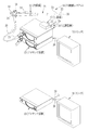
図1に示すように、第1実施形態の内視鏡システム10は、体腔内を撮影する内視鏡11と、内視鏡画像を生成するプロセッサ装置12、13と、体腔内を照明する光を内視鏡11に供給する光源装置14と、内視鏡画像を表示するモニタ15、16と、使用するプロセッサ装置12、13の切替えを行う切替器17とから構成されている。内視鏡システム10は、カート(図示省略)に各装置一式が搭載されて使用される。
[First Embodiment]
As shown in FIG. 1, an endoscope system 10 according to the first embodiment includes an endoscope 11 that images a body cavity, processor devices 12 and 13 that generate endoscopic images, and light that illuminates the body cavity. Are provided to the endoscope 11,
内視鏡11は、体腔内に挿入される可撓性を有した挿入部18と、挿入部18の基端部分に連設された操作部19と、プロセッサ装置12又は13、及び光源装置14に接続されるユニバーサルコード20とを備えている。
The endoscope 11 includes a flexible insertion portion 18 that is inserted into a body cavity, an
挿入部18の先端には、撮像素子としてCCD(charge coupled device)21(図2参照)を内蔵した先端部22が設けられている。先端部22の後方には、複数の湾曲駒(図示省略)を連結した湾曲部23が設けられている。湾曲部23は、操作部19に設けられたアングルノブ24が操作されて、挿入部18内に挿設されたワイヤ(図示省略)が押し引きされることにより、上下左右方向に湾曲動作する。これにより、先端部22が体腔内の所望の方向に向けられる。
A
ユニバーサルコード20の基端は、コネクタ25に連結されている。コネクタ25は、複合タイプのものであり、コネクタ25にはプロセッサ装置12又は13が接続される他、光源装置14が接続される。以下では、コネクタ25がプロセッサ装置12に接続されている場合を説明する。
The base end of the
プロセッサ装置12は、CCD21から出力された撮像信号を受信し、受信した撮像信号に各種信号処理を施して画像データに変換する。プロセッサ装置12で変換された画像データは、プロセッサ装置12にケーブル26で接続されたモニタ15に内視鏡画像として表示される。プロセッサ装置12は、ケーブル27を介して切替器17と電気的に接続され、内視鏡システム10の動作を統括的に制御する。
The processor device 12 receives the imaging signal output from the
プロセッサ装置13は、12と同様の処理を行い、ケーブル28で接続されたモニタ16に内視鏡画像を表示させる。プロセッサ装置13は、ケーブル29を介して切替器17と電気的に接続され、内視鏡システム10の動作を統括的に制御する。なお、ケーブル26〜29には、LAN、ANSI/TIA/EIA-232-F-1997(俗にいうRS−232)などを用いればよい。
The processor device 13 performs the same processing as 12 and displays an endoscopic image on the
切替器17は、ケーブル36を介して光源装置14と電気的に接続されている。なお、ケーブル36には、LAN、ANSI/TIA/EIA-232-F-1997(俗にいうRS−232)などを用いればよい。
The
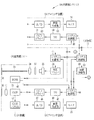
図2において、先端部22の端面30(図1参照)には、照明窓31、観察窓32、鉗子出口(図示省略)、及び送気送水ノズル(図示省略)が設けられている。照明窓31からは、光源装置14からライトガイド33を介して導かれた照明光が観察部位に照射される。観察窓32には、観察部位の像光が入射される。鉗子出口は、挿入部18内に配設された鉗子チャンネル(図示省略)に接続され、操作部19に設けられた鉗子口34(図1参照)に連通している。鉗子口34には、注射針や高周波メスなどが先端に配された各種処置具が挿通され、各種処置具の先端が鉗子出口から露出される。送気送水ノズルは、操作部19に設けられた送気送水ボタン35(図1参照)の操作に応じて、光源装置14に内蔵された送気送水機構(図示省略)から供給される洗浄水や空気を、観察窓32に向けて噴射する。
In FIG. 2, an
内視鏡11に内蔵されたCCD21は、観察窓32に対向して設けられた対物レンズ41の結像位置に配設されている。内視鏡11には、CCD21の他に、相関二重サンプリング/プログラマブルゲインアンプ(以下、「CDS/PGA」という。)42、ROM43などが設けられている。CCD21は、観察窓32及び対物レンズ41を介して入射した観察部位の像光を撮像し、像光に応じた撮像信号を出力する。CDS/PGA42は、CCD21から出力される撮像信号に対してノイズ除去と増幅とを行う。ROM43には、内視鏡11固有の識別情報(例えば、内視鏡11のシリアルナンバー)が記憶されている。詳しくは後述するが、ROM43に記憶されている識別情報は、プロセッサ装置12、13の選択に用いられる。
The
プロセッサ装置12には、システム制御部44、タイミングジェネレータ(以下、「TG」という。)45、CCDドライバ46、A/D変換器(以下、「A/D」という。)47、画像生成部48が設けられている。システム制御部44は、光源装置14のシステム制御部54と通信を行うとともに、プロセッサ装置12の各部を統括的に制御する。
The processor device 12 includes a
TG45は、システム制御部44の制御の下、タイミング信号(クロックパルス)をCCDドライバ46に入力する。CCDドライバ46は、入力されたタイミング信号に基づいて、駆動信号をCCD21に入力し、CCD21の蓄積電荷の読出しタイミングやCCD21の電子シャッタ速度などを制御する。
The
A/D47は、CDS/PGA42から出力されるアナログの撮像信号をデジタルの画像データに変換する。画像生成部48は、A/D47でデジタル化された画像データに対して各種の画像処理を施し、内視鏡画像を生成する。また、画像生成部48は、生成した内視鏡画像をモニタ15の形式に対応したビデオ信号(コンポーネント信号、コンポジット信号など)に変換し、そのビデオ信号をモニタ15に出力する。これにより、内視鏡画像がモニタ15に表示される。
The A /
プロセッサ装置13には、システム制御部49、タイミングジェネレータ(以下、「TG」という。)50、CCDドライバ51、A/D変換器(以下、「A/D」という。)52、画像生成部53が設けられている。
The processor device 13 includes a
光源装置14には、システム制御部54、光源55、光源ドライバ56、絞り機構57、集光レンズ58などが設けられている。システム制御部54は、光源装置14の各部を統括的に制御する。
The light source device 14 includes a
光源55は、キセノンランプやハロゲンランプなどからなり、光源ドライバ56により駆動制御される。絞り機構57は、光源55の光射出側に配置され、集光レンズ58に入射される光量を増減させる。集光レンズ58は、絞り機構57を通過した光を集め、光源装置14に接続された内視鏡11のライトガイド33の入射端に光を導く。ライトガイド33は、内視鏡11の基端から先端部22まで挿通され、射出端が照明窓31に接続されている。
The
切替器17には、システム制御部59、及び接続切替部60が設けられている。システム制御部59は、光源装置14のシステム制御部54が、プロセッサ装置12のシステム制御部44、及びプロセッサ装置13のシステム制御部49のどちらと通信を行うかを決定するとともに、切替器17の各部を統括的に制御する。光源装置14のシステム制御部54は、プロセッサ装置12のシステム制御部44とプロセッサ装置13のシステム制御部49のうち、切替器17のシステム制御部59が決定した一方と通信を行う。
The
システム制御部54がいずれのシステム制御部44、49と通信を行うかをシステム制御部59で決定する方法は、内視鏡11のROM43に記憶された識別情報に基づいて行われる。識別情報は、ROM43からユニバーサルコード20及びコネクタ25を介して光源装置14のシステム制御部54に入力される。そして、光源装置14のシステム制御部54からケーブル36を介して切替器17のシステム制御部59に取得される。また、識別情報は、ROM43からユニバーサルコード20及びコネクタ25を介して内視鏡11が接続されたプロセッサ装置12のシステム制御部44に入力される。そして、プロセッサ装置12のシステム制御部44からケーブル27を介して切替器17のシステム制御部59に取得される。その一方、内視鏡11が接続されていないプロセッサ装置13からは取得されない。システム制御部59は、光源装置14を介して取得された識別情報がプロセッサ装置12からも取得されたことを受け、光源装置14のシステム制御部54がプロセッサ装置12のシステム制御部44と通信を行うと決定する。なお、内視鏡11がプロセッサ装置13に接続されている場合には、プロセッサ装置13を介して識別情報が取得されるので、光源装置14のシステム制御部54がプロセッサ装置13のシステム制御部49と通信を行うことが決定される。
The
接続切替部60は、システム制御部59による決定に基づいて、光源装置14のシステム制御部54と、プロセッサ装置12のシステム制御部44、及びプロセッサ装置13のシステム制御部49のいずれか一方との接続を切り替える。本実施形態では、接続切替部60は、光源装置14のシステム制御部54と、プロセッサ装置12のシステム制御部44とを接続し、通信可能な状態にする。
Based on the determination by the
次に、上記構成の内視鏡システム10の処理手順について、図3のフローチャートを参照しながら説明する。医師は、内視鏡システム10で検査を実施する際、プロセッサ装置12又は13、及び光源装置14のそれぞれに内視鏡11を接続する(図1参照)とともに、内視鏡システム10の電源を入れる。以下では、内視鏡11がプロセッサ装置12に接続された場合を説明する。 Next, the processing procedure of the endoscope system 10 having the above configuration will be described with reference to the flowchart of FIG. When a doctor performs an examination with the endoscope system 10, the doctor 11 connects the endoscope 11 to each of the processor device 12 or 13 and the light source device 14 (see FIG. 1), and powers the endoscope system 10. Put in. Hereinafter, a case where the endoscope 11 is connected to the processor device 12 will be described.
内視鏡システム10に電源が入ると、切替器17のシステム制御部59は、内視鏡11の識別情報を、光源装置14を介して取得するとともに、プロセッサ装置12又は13を介して取得する。そして、切替器17のシステム制御部59は、光源装置14のシステム制御部54が、プロセッサ装置12のシステム制御部44、及びプロセッサ装置13のシステム制御部49のどちらと通信を行うかを決定する。内視鏡11の識別情報がプロセッサ装置12を介して取得された場合には、切替器17のシステム制御部59は、光源装置14のシステム制御部54がプロセッサ装置12のシステム制御部44と通信を行うと決定する。一方、内視鏡11の識別情報がプロセッサ装置13を介して取得された場合には、切替器17のシステム制御部59は、光源装置14のシステム制御部54がプロセッサ装置13のシステム制御部49と通信を行うと決定する。本実施形態の説明では、内視鏡11がプロセッサ装置12に接続されているので、光源装置14のシステム制御部54がプロセッサ装置12のシステム制御部44と通信を行うと決定される。
When the endoscope system 10 is turned on, the
医師は、プロセッサ装置12に設けられた検査開始ボタン(図示省略)を操作する。これにより、内視鏡システム10の各部に検査の開始が指示される。 The doctor operates an examination start button (not shown) provided on the processor device 12. This instructs each part of the endoscope system 10 to start the examination.
プロセッサ装置12のシステム制御部44は、検査開始の指示を受けると、TG45を制御し、CCDドライバ46によるCCD21の駆動を開始させる。CCD21は、CCDドライバ46の駆動に応じて、観察窓32及び対物レンズ41を介して入射した観察部位の像光を撮像し、像光に応じた撮像信号を出力する。
When receiving the instruction to start the inspection, the
出力された撮像信号は、CDS/PGA42でノイズ除去と増幅とが行われる。ノイズ除去と増幅とが行われた撮像信号は、A/D47に入力され、デジタルの画像データに変換される。画像データは、画像生成部48に入力される。画像生成部48は、入力された画像データに対して各種の画像処理を施し、画像データから内視鏡画像を生成する。また、画像生成部48は、生成した内視鏡画像をモニタ15の形式に対応したビデオ信号に変換し、そのビデオ信号をモニタ15に出力する。これにより、内視鏡画像がモニタ15に表示される。
The output imaging signal is subjected to noise removal and amplification by the CDS /
医師は、モニタ15に内視鏡画像が表示されると、患者の体腔内に内視鏡11の先端部22を挿入し、体腔内の観察を始める。
When the endoscopic image is displayed on the
以上説明したように、内視鏡固有の識別情報に基づいて、内視鏡が接続されたプロセッサ装置を検出する切替器17を備えたから、光源装置14に複数個のポートを設ける必要がない。また、特許文献1に記載の内視鏡システムのように、検出線が配設された内視鏡を別途用意したり既存の内視鏡を改造したりする必要はない。ひいては、複数台のプロセッサ装置に対する光源装置の共通化が、既存の機器を改造することなく実現できる。
As described above, since the
[第2実施形態]
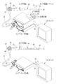
図4に示すように、第2実施形態の内視鏡システム61は、内視鏡11、62を備えている。内視鏡11は、ユニバーサルコード20の基端に連結されたコネクタ25を介して、プロセッサ装置12が接続される他、光源装置14が接続される。
[Second Embodiment]
As shown in FIG. 4, the endoscope system 61 of the second embodiment includes endoscopes 11 and 62. The endoscope 11 is connected to the light source device 14 in addition to the processor device 12 via a
一方、内視鏡62は、プロセッサ装置13及び光源装置14に接続されるユニバーサルコード65を備えている。ユニバーサルコード65の基端は、コネクタ70に連結されている。コネクタ70は、複合タイプのものであり、コネクタ70にはプロセッサ装置13が接続される他、光源装置14が接続される。内視鏡62については、図面に符号を付してその詳しい説明を省略する。なお、内視鏡11の構成と、内視鏡62の構成とを区別するため、互いに異なる符合を付した。例えば、挿入部に付した符号は、18と63とで異なる。以下では、光源装置14には、内視鏡11のコネクタ25が接続されて、且つ、内視鏡62のコネクタ70が接続されていない場合を説明する。
On the other hand, the endoscope 62 includes a
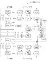
図5において、システム制御部54がいずれのシステム制御部44、49と通信を行うかをシステム制御部59で決定する方法は、内視鏡11のROM43に記憶された識別情報、及び内視鏡62のROM83に記憶された識別情報に基づいて行われる。内視鏡11の識別情報は、光源装置14を介して切替器17のシステム制御部59に取得されるとともに、内視鏡11が接続されたプロセッサ装置12を介して切替器17のシステム制御部59に取得される。その一方、内視鏡62の識別情報は、ROM83からユニバーサルコード65及びコネクタ70を介してプロセッサ装置13のシステム制御部49に入力される。そして、プロセッサ装置13のシステム制御部49からケーブル29を介して切替器17のシステム制御部59に取得される。システム制御部59は、光源装置14を介して取得された識別情報とプロセッサ装置12から取得された識別情報とが一致したことを受け、光源装置14のシステム制御部54がプロセッサ装置12のシステム制御部44と通信を行うと決定する。一方、光源装置14に内視鏡11ではなく内視鏡62が接続されている場合には、光源装置14を介して取得された識別情報とプロセッサ装置13を介して取得された識別情報とが一致するので、光源装置14のシステム制御部54がプロセッサ装置13のシステム制御部49と通信を行うことが決定される。なお、上記第1実施形態と同様の構成については、その説明を省略する。
In FIG. 5, the
次に、上記構成の内視鏡システム61の処理手順について、図6のフローチャートを参照しながら説明する。医師は、図4に示すように各装置が接続された内視鏡システム61で検査を実施する場合、内視鏡システム61の電源を入れる。 Next, the processing procedure of the endoscope system 61 having the above configuration will be described with reference to the flowchart of FIG. As shown in FIG. 4, the doctor turns on the power of the endoscope system 61 when performing an examination with the endoscope system 61 to which each device is connected.
内視鏡システム61に電源が入ると、切替器17のシステム制御部59は、プロセッサ装置12、13に接続された内視鏡の識別情報を、プロセッサ装置12、13を介して取得するとともに、光源装置14に接続された内視鏡の識別情報を、光源装置14を介して取得する。そして、切替器17のシステム制御部59は、光源装置14のシステム制御部54が、プロセッサ装置12のシステム制御部44、及びプロセッサ装置13のシステム制御部49のどちらと通信を行うかを決定する。光源装置14に接続された内視鏡の識別情報がプロセッサ装置12から取得された場合には、切替器17のシステム制御部59は、光源装置14のシステム制御部54がプロセッサ装置12のシステム制御部44と通信を行うと決定する。一方、光源装置14に接続された内視鏡の識別情報がプロセッサ装置13から取得された場合には、切替器17のシステム制御部59は、光源装置14のシステム制御部54がプロセッサ装置13のシステム制御部49と通信を行うと決定する。本実施形態の説明では、光源装置14に内視鏡11が接続されているので、光源装置14のシステム制御部54が、プロセッサ装置12のシステム制御部44と通信を行うと決定される。なお、上記第1実施形態と同様の処理手順及び効果については、その説明を省略する。
When the endoscope system 61 is turned on, the
なお、上記各実施形態では、プロセッサ装置が2台である場合を例に説明したが、3台以上であってもよい。 In each of the above-described embodiments, the case where there are two processor devices has been described as an example. However, three or more processor devices may be used.
また、上記各実施形態では、内視鏡のROMに記憶された識別情報に基づいて使用するプロセッサ装置を選択したが、内視鏡のコネクタに設けられたピンの配置や形状をプロセッサ装置で判別し、そのピンの配置や形状に基づいて内視鏡を識別してもよい。また、画像データの付帯情報を画像生成部で取得して、その付帯情報に基づいて内視鏡を識別してもよい。 In each of the above embodiments, the processor device to be used is selected based on the identification information stored in the ROM of the endoscope. However, the arrangement and shape of the pins provided on the connector of the endoscope are determined by the processor device. Then, the endoscope may be identified based on the arrangement and shape of the pins. Further, the supplementary information of the image data may be acquired by the image generation unit, and the endoscope may be identified based on the supplementary information.
また、上記各実施形態では、内視鏡固有の識別情報に基づいて、使用するプロセッサ装置を選択したが、電源が入っているプロセッサ装置を選択するようにしてもよい。この場合において、両方のプロセッサ装置(プロセッサ装置が3台以上の場合は、複数台のプロセッサ装置)に電源が入っている場合には、所定の規則に基づいて、使用するプロセッサ装置を選択する。所定の規則としては、電源が入れられた順番、予め設定された優先順位、使用状況(頻度や、直前に使用したものを選択する)を切替器17内に記憶しておいて、それを使うことなどが挙げられる。
In each of the above embodiments, the processor device to be used is selected based on the identification information unique to the endoscope. However, a processor device that is powered on may be selected. In this case, when both of the processor devices (a plurality of processor devices when there are three or more processor devices) are turned on, the processor device to be used is selected based on a predetermined rule. As predetermined rules, the order in which the power is turned on, the preset priority order, and the usage status (select the frequency and the last used one) are stored in the
また、上記各実施形態では、図1又は図4に示すように、切替器17は筐体に収められ、光源装置14の上面に載置したが、内視鏡システム10、61が搭載されるカートに内蔵又は取り付けられていてもよい。
Moreover, in each said embodiment, as shown in FIG. 1 or FIG. 4, although the
また、上記各実施形態で示した内視鏡システム10、61は、一例にすぎず、本発明の趣旨を逸脱しなければ、如何様な態様にも適宜変更することができる。 Moreover, the endoscope systems 10 and 61 shown in the above embodiments are merely examples, and can be appropriately changed to any form without departing from the gist of the present invention.
10、61 内視鏡システム
11、62 内視鏡
12、13 プロセッサ装置
14 光源装置
17 切替器
21 CCD(charge coupled device)
43、83 ROM
59 システム制御部
60 接続切替部
DESCRIPTION OF SYMBOLS 10, 61 Endoscopy system 11, 62 Endoscope 12, 13 Processor unit 14
43, 83 ROM
59
Claims (8)
前記内視鏡が着脱自在に接続され、前記被検体内を照明する光を前記内視鏡に供給する光源装置と、
1台の前記光源装置と複数台の前記プロセッサ装置との接続が可能で、複数台の前記プロセッサ装置の中から、前記光源装置と通信する1台の前記プロセッサ装置を決定する切替器であり、
前記内視鏡が接続された前記光源装置から、接続された前記内視鏡の固有の識別情報を取得する機能と、複数台の前記プロセッサ装置のうち前記内視鏡が接続された前記プロセッサ装置から、接続された前記内視鏡の固有の前記識別情報を取得する機能とを有し、
複数台の前記プロセッサ装置からの前記識別情報の取得の有無、又は前記光源装置を取得元とする前記識別情報と前記プロセッサ装置を取得元とする前記識別情報との一致状況に基づいて、前記光源装置と通信する1台の前記プロセッサ装置を決定する切替器とを備えていることを特徴とする内視鏡システム。 Endoscope imaging device with built is detachably connected, and pulp processor device to generate an endoscope image based on the imaging signal output from the imaging element,
The endoscope is detachably connected, and a light source device you provide light for illuminating the inside of the subject in the endoscope,
A switch that can connect one light source device and a plurality of processor devices, and determines one processor device that communicates with the light source device from among the plurality of processor devices,
A function of acquiring unique identification information of the connected endoscope from the light source device to which the endoscope is connected, and the processor device to which the endoscope is connected among a plurality of the processor devices And having the function of acquiring the identification information unique to the connected endoscope,
The light source based on the presence or absence of acquisition of the identification information from a plurality of the processor devices, or the matching status of the identification information from the light source device and the identification information from the processor device An endoscope system comprising: a switching unit that determines one processor device that communicates with a device.
前記切替器は、前記内視鏡が接続された1台の前記プロセッサ装置から前記識別情報が取得されたことを受けて、当該プロセッサ装置を前記光源装置と通信する1台の前記プロセッサ装置に決定することを特徴とする請求項1に記載の内視鏡システム。In response to the identification information being acquired from the one processor device connected to the endoscope, the switch determines the processor device as one processor device that communicates with the light source device. The endoscope system according to claim 1, wherein:
前記切替器は、前記第1及び第2のプロセッサ装置からそれぞれ、前記第1内視鏡の識別情報である第1識別情報と前記第2内視鏡の前記識別情報である第2識別情報とを取得し、前記第1及び第2識別情報のうち、前記光源装置を取得元とする前記識別情報と一致する識別情報を判別し、判別した識別情報の取得元である前記プロセッサ装置を前記光源装置と通信する1台の前記プロセッサ装置に決定することを特徴とする請求項1に記載の内視鏡システム。The switch includes first identification information that is identification information of the first endoscope and second identification information that is identification information of the second endoscope, respectively, from the first and second processor devices. Among the first and second identification information, the identification information that matches the identification information from the light source device is determined, and the processor device that is the acquisition source of the determined identification information is determined as the light source. The endoscope system according to claim 1, wherein the processor device is determined to be one processor device that communicates with the device.
1台の前記光源装置と複数台の前記プロセッサ装置との接続が可能で、複数台の前記プロセッサ装置の中から、前記光源装置と通信する1台の前記プロセッサ装置を決定する切替器であり、
前記内視鏡が接続された前記光源装置から、接続された前記内視鏡の固有の識別情報を取得する機能と、複数台の前記プロセッサ装置のうち前記内視鏡が接続された前記プロセッサ装置から、接続された前記内視鏡の固有の前記識別情報を取得する機能とを有し、
複数台の前記プロセッサ装置からの前記識別情報の取得の有無、又は前記光源装置を取得元とする前記識別情報と前記プロセッサ装置を取得元とする前記識別情報との一致状況に基づいて、前記光源装置と通信する1台の前記プロセッサ装置を決定することを特徴とする切替器。 Endoscope imaging device with built is detachably connected, said product to pulp processor apparatus an endoscopic image based on the imaging signal output from the imaging device, and the endoscope is detachably connected is used the light that illuminates the inside of the subject to an endoscope system having a light source device and that be supplied to the endoscope,
A switch that can connect one light source device and a plurality of processor devices, and determines one processor device that communicates with the light source device from among the plurality of processor devices,
A function of acquiring unique identification information of the connected endoscope from the light source device to which the endoscope is connected, and the processor device to which the endoscope is connected among a plurality of the processor devices And having the function of acquiring the identification information unique to the connected endoscope,
The light source based on the presence or absence of acquisition of the identification information from a plurality of the processor devices, or the matching status of the identification information from the light source device and the identification information from the processor device A switch for determining one processor device to communicate with a device.
前記切替器は、前記内視鏡が接続された1台の前記プロセッサ装置から前記識別情報が取得されたことを受けて、当該プロセッサ装置を前記光源装置と通信する1台の前記プロセッサ装置に決定することを特徴とする請求項5に記載の切替器。In response to the identification information being acquired from the one processor device connected to the endoscope, the switch determines the processor device as one processor device that communicates with the light source device. The switching device according to claim 5, wherein:
前記切替器は、前記第1及び第2のプロセッサ装置からそれぞれ、前記第1内視鏡の識別情報である第1識別情報と前記第2内視鏡の前記識別情報である第2識別情報とを取得し、前記第1及び第2識別情報のうち、前記光源装置を取得元とする前記識別情報と一致する識別情報を判別し、判別した識別情報の取得元である前記プロセッサ装置を前記光源装置と通信する1台の前記プロセッサ装置に決定することを特徴とする請求項5に記載の切替器。The switch includes first identification information that is identification information of the first endoscope and second identification information that is identification information of the second endoscope, respectively, from the first and second processor devices. Among the first and second identification information, the identification information that matches the identification information from the light source device is determined, and the processor device that is the acquisition source of the determined identification information is determined as the light source. The switching device according to claim 5, wherein the switching device is determined to be one processor device that communicates with a device.
Priority Applications (1)
| Application Number | Priority Date | Filing Date | Title |
|---|---|---|---|
| JP2008171952A JP5288909B2 (en) | 2008-07-01 | 2008-07-01 | Endoscope system and switch |
Applications Claiming Priority (1)
| Application Number | Priority Date | Filing Date | Title |
|---|---|---|---|
| JP2008171952A JP5288909B2 (en) | 2008-07-01 | 2008-07-01 | Endoscope system and switch |
Publications (2)
| Publication Number | Publication Date |
|---|---|
| JP2010011893A JP2010011893A (en) | 2010-01-21 |
| JP5288909B2 true JP5288909B2 (en) | 2013-09-11 |
Family
ID=41698646
Family Applications (1)
| Application Number | Title | Priority Date | Filing Date |
|---|---|---|---|
| JP2008171952A Expired - Fee Related JP5288909B2 (en) | 2008-07-01 | 2008-07-01 | Endoscope system and switch |
Country Status (1)
| Country | Link |
|---|---|
| JP (1) | JP5288909B2 (en) |
Families Citing this family (1)
| Publication number | Priority date | Publication date | Assignee | Title |
|---|---|---|---|---|
| WO2017047321A1 (en) * | 2015-09-18 | 2017-03-23 | オリンパス株式会社 | Signal processor |
Family Cites Families (1)
| Publication number | Priority date | Publication date | Assignee | Title |
|---|---|---|---|---|
| JP2001204684A (en) * | 2000-01-25 | 2001-07-31 | Olympus Optical Co Ltd | Endoscope device |
-
2008
- 2008-07-01 JP JP2008171952A patent/JP5288909B2/en not_active Expired - Fee Related
Also Published As
| Publication number | Publication date |
|---|---|
| JP2010011893A (en) | 2010-01-21 |
Similar Documents
| Publication | Publication Date | Title |
|---|---|---|
| JP5127639B2 (en) | Endoscope system and method of operating the same | |
| JP5893124B2 (en) | Laparoscopic system | |
| KR101556881B1 (en) | Endoscope | |
| JP4856286B2 (en) | Endoscope system | |
| CN105358042B (en) | Endoscope tip position visual detector and thermal management | |
| US8537210B2 (en) | Controlling light source with endoscope type | |
| JP5203861B2 (en) | Endoscope system and method of operating the same | |
| JP5769892B2 (en) | Endoscope | |
| JP2005169009A (en) | Endoscope system and endoscope | |
| JP2005058618A (en) | Endoscope and cap | |
| JP5390146B2 (en) | Auxiliary tool and endoscope system using the same | |
| JP4276747B2 (en) | Endoscope device | |
| JP2011206185A (en) | Endoscope system and failure detection method of the same | |
| JP5459991B2 (en) | Endoscope system | |
| JP5288909B2 (en) | Endoscope system and switch | |
| EP1769730A1 (en) | Light source device and fluorescence observation system | |
| JP2012120572A (en) | Endoscope system | |
| JP2010051440A (en) | Endoscope system, and method and instrument for determining breakage state of light guide | |
| JP4891531B2 (en) | Endoscope device | |
| JP5371941B2 (en) | Endoscope system | |
| JP4373726B2 (en) | Auto fluorescence observation device | |
| JP2009213630A (en) | Endoscope system and processor | |
| JP5384894B2 (en) | Adapter and endoscope system using the adapter | |
| JP2007014423A (en) | Endoscope device | |
| JP2010148646A (en) | Endoscope, endoscope system and method of driving endoscope |
Legal Events
| Date | Code | Title | Description |
|---|---|---|---|
| A711 | Notification of change in applicant |
Free format text: JAPANESE INTERMEDIATE CODE: A711 Effective date: 20100619 |
|
| A621 | Written request for application examination |
Free format text: JAPANESE INTERMEDIATE CODE: A621 Effective date: 20110118 |
|
| A977 | Report on retrieval |
Free format text: JAPANESE INTERMEDIATE CODE: A971007 Effective date: 20120926 |
|
| A131 | Notification of reasons for refusal |
Free format text: JAPANESE INTERMEDIATE CODE: A131 Effective date: 20121010 |
|
| A521 | Written amendment |
Free format text: JAPANESE INTERMEDIATE CODE: A523 Effective date: 20121127 |
|
| A01 | Written decision to grant a patent or to grant a registration (utility model) |
Free format text: JAPANESE INTERMEDIATE CODE: A01 Effective date: 20130508 |
|
| A61 | First payment of annual fees (during grant procedure) |
Free format text: JAPANESE INTERMEDIATE CODE: A61 Effective date: 20130604 |
|
| LAPS | Cancellation because of no payment of annual fees |