JP5285690B2 - Parallel computer system, computer-implemented method, computer-readable recording medium and computer program for dynamically rerouting node traffic on parallel computer system - Google Patents
Parallel computer system, computer-implemented method, computer-readable recording medium and computer program for dynamically rerouting node traffic on parallel computer system Download PDFInfo
- Publication number
- JP5285690B2 JP5285690B2 JP2010503440A JP2010503440A JP5285690B2 JP 5285690 B2 JP5285690 B2 JP 5285690B2 JP 2010503440 A JP2010503440 A JP 2010503440A JP 2010503440 A JP2010503440 A JP 2010503440A JP 5285690 B2 JP5285690 B2 JP 5285690B2
- Authority
- JP
- Japan
- Prior art keywords
- node
- network
- nodes
- computer system
- parallel computer
- Prior art date
- Legal status (The legal status is an assumption and is not a legal conclusion. Google has not performed a legal analysis and makes no representation as to the accuracy of the status listed.)
- Expired - Fee Related
Links
- 238000000034 method Methods 0.000 title claims description 33
- 238000004590 computer program Methods 0.000 title claims 7
- 238000012544 monitoring process Methods 0.000 claims description 11
- 230000007246 mechanism Effects 0.000 claims description 10
- 230000008569 process Effects 0.000 claims description 10
- 238000004364 calculation method Methods 0.000 claims description 5
- 238000001514 detection method Methods 0.000 claims description 4
- 238000010586 diagram Methods 0.000 description 13
- 108090000623 proteins and genes Proteins 0.000 description 13
- 238000004891 communication Methods 0.000 description 9
- 238000012545 processing Methods 0.000 description 6
- 238000005192 partition Methods 0.000 description 4
- 230000008439 repair process Effects 0.000 description 3
- 238000012360 testing method Methods 0.000 description 3
- 238000002347 injection Methods 0.000 description 2
- 239000007924 injection Substances 0.000 description 2
- 238000011084 recovery Methods 0.000 description 2
- 239000002699 waste material Substances 0.000 description 2
- 230000004888 barrier function Effects 0.000 description 1
- 230000008901 benefit Effects 0.000 description 1
- 230000005540 biological transmission Effects 0.000 description 1
- 238000012937 correction Methods 0.000 description 1
- 238000011161 development Methods 0.000 description 1
- 230000006870 function Effects 0.000 description 1
- 238000007689 inspection Methods 0.000 description 1
- 238000005457 optimization Methods 0.000 description 1
- 230000000717 retained effect Effects 0.000 description 1
- 230000003068 static effect Effects 0.000 description 1
- 230000001360 synchronised effect Effects 0.000 description 1
- 238000012546 transfer Methods 0.000 description 1
Images


Classifications
-
- H—ELECTRICITY
- H04—ELECTRIC COMMUNICATION TECHNIQUE
- H04L—TRANSMISSION OF DIGITAL INFORMATION, e.g. TELEGRAPHIC COMMUNICATION
- H04L45/00—Routing or path finding of packets in data switching networks
- H04L45/22—Alternate routing
-
- G—PHYSICS
- G06—COMPUTING; CALCULATING OR COUNTING
- G06F—ELECTRIC DIGITAL DATA PROCESSING
- G06F11/00—Error detection; Error correction; Monitoring
- G06F11/07—Responding to the occurrence of a fault, e.g. fault tolerance
- G06F11/16—Error detection or correction of the data by redundancy in hardware
- G06F11/20—Error detection or correction of the data by redundancy in hardware using active fault-masking, e.g. by switching out faulty elements or by switching in spare elements
- G06F11/202—Error detection or correction of the data by redundancy in hardware using active fault-masking, e.g. by switching out faulty elements or by switching in spare elements where processing functionality is redundant
- G06F11/2023—Failover techniques
- G06F11/203—Failover techniques using migration
-
- G—PHYSICS
- G06—COMPUTING; CALCULATING OR COUNTING
- G06F—ELECTRIC DIGITAL DATA PROCESSING
- G06F15/00—Digital computers in general; Data processing equipment in general
- G06F15/16—Combinations of two or more digital computers each having at least an arithmetic unit, a program unit and a register, e.g. for a simultaneous processing of several programs
- G06F15/163—Interprocessor communication
- G06F15/173—Interprocessor communication using an interconnection network, e.g. matrix, shuffle, pyramid, star, snowflake
- G06F15/17356—Indirect interconnection networks
- G06F15/17368—Indirect interconnection networks non hierarchical topologies
- G06F15/17381—Two dimensional, e.g. mesh, torus
-
- H—ELECTRICITY
- H04—ELECTRIC COMMUNICATION TECHNIQUE
- H04L—TRANSMISSION OF DIGITAL INFORMATION, e.g. TELEGRAPHIC COMMUNICATION
- H04L12/00—Data switching networks
- H04L12/28—Data switching networks characterised by path configuration, e.g. LAN [Local Area Networks] or WAN [Wide Area Networks]
-
- H—ELECTRICITY
- H04—ELECTRIC COMMUNICATION TECHNIQUE
- H04L—TRANSMISSION OF DIGITAL INFORMATION, e.g. TELEGRAPHIC COMMUNICATION
- H04L41/00—Arrangements for maintenance, administration or management of data switching networks, e.g. of packet switching networks
- H04L41/06—Management of faults, events, alarms or notifications
- H04L41/0654—Management of faults, events, alarms or notifications using network fault recovery
- H04L41/0659—Management of faults, events, alarms or notifications using network fault recovery by isolating or reconfiguring faulty entities
-
- H—ELECTRICITY
- H04—ELECTRIC COMMUNICATION TECHNIQUE
- H04L—TRANSMISSION OF DIGITAL INFORMATION, e.g. TELEGRAPHIC COMMUNICATION
- H04L45/00—Routing or path finding of packets in data switching networks
- H04L45/02—Topology update or discovery
-
- H—ELECTRICITY
- H04—ELECTRIC COMMUNICATION TECHNIQUE
- H04L—TRANSMISSION OF DIGITAL INFORMATION, e.g. TELEGRAPHIC COMMUNICATION
- H04L45/00—Routing or path finding of packets in data switching networks
- H04L45/28—Routing or path finding of packets in data switching networks using route fault recovery
-
- H—ELECTRICITY
- H04—ELECTRIC COMMUNICATION TECHNIQUE
- H04L—TRANSMISSION OF DIGITAL INFORMATION, e.g. TELEGRAPHIC COMMUNICATION
- H04L45/00—Routing or path finding of packets in data switching networks
- H04L45/34—Source routing
-
- G—PHYSICS
- G06—COMPUTING; CALCULATING OR COUNTING
- G06F—ELECTRIC DIGITAL DATA PROCESSING
- G06F11/00—Error detection; Error correction; Monitoring
- G06F11/07—Responding to the occurrence of a fault, e.g. fault tolerance
- G06F11/16—Error detection or correction of the data by redundancy in hardware
- G06F11/20—Error detection or correction of the data by redundancy in hardware using active fault-masking, e.g. by switching out faulty elements or by switching in spare elements
- G06F11/202—Error detection or correction of the data by redundancy in hardware using active fault-masking, e.g. by switching out faulty elements or by switching in spare elements where processing functionality is redundant
- G06F11/2038—Error detection or correction of the data by redundancy in hardware using active fault-masking, e.g. by switching out faulty elements or by switching in spare elements where processing functionality is redundant with a single idle spare processing component
-
- G—PHYSICS
- G06—COMPUTING; CALCULATING OR COUNTING
- G06F—ELECTRIC DIGITAL DATA PROCESSING
- G06F11/00—Error detection; Error correction; Monitoring
- G06F11/07—Responding to the occurrence of a fault, e.g. fault tolerance
- G06F11/16—Error detection or correction of the data by redundancy in hardware
- G06F11/20—Error detection or correction of the data by redundancy in hardware using active fault-masking, e.g. by switching out faulty elements or by switching in spare elements
- G06F11/202—Error detection or correction of the data by redundancy in hardware using active fault-masking, e.g. by switching out faulty elements or by switching in spare elements where processing functionality is redundant
- G06F11/2051—Error detection or correction of the data by redundancy in hardware using active fault-masking, e.g. by switching out faulty elements or by switching in spare elements where processing functionality is redundant in regular structures
-
- H—ELECTRICITY
- H04—ELECTRIC COMMUNICATION TECHNIQUE
- H04L—TRANSMISSION OF DIGITAL INFORMATION, e.g. TELEGRAPHIC COMMUNICATION
- H04L45/00—Routing or path finding of packets in data switching networks
Landscapes
- Engineering & Computer Science (AREA)
- Computer Networks & Wireless Communication (AREA)
- Signal Processing (AREA)
- Theoretical Computer Science (AREA)
- Physics & Mathematics (AREA)
- General Engineering & Computer Science (AREA)
- General Physics & Mathematics (AREA)
- Quality & Reliability (AREA)
- Computer Hardware Design (AREA)
- Mathematical Physics (AREA)
- Software Systems (AREA)
- Hardware Redundancy (AREA)
- Multi Processors (AREA)
- Computer And Data Communications (AREA)
- Data Exchanges In Wide-Area Networks (AREA)
- Retry When Errors Occur (AREA)
Description
本発明は、並列コンピュータ・システム内の障害回復に係り、さらに詳細に説明すれば、超並列コンピュータ・システム上で実行中のアプリケーションを再始動することなく、ヒント・ビットを使用して、超並列コンピュータ・システムの計算ノード上のノード・トラフィックを動的に再経路指定するための装置及び方法に係る。 The present invention relates to failure recovery in parallel computer systems and, more particularly, uses hint bits to restart massively parallel applications without restarting applications running on the massively parallel computer system. An apparatus and method for dynamically rerouting node traffic on a computing node of a computer system.
高性能のコンピュータ・システムについては、故障時間及び修理コストを減少させるために、効率的な障害回復が重要である。多数の計算ノードを有する並列コンピュータ・システムでは、単一コンポーネントの障害が生じる結果として、大きな部分又はコンピュータ全体が、修理のためにオフラインに強制されることがある。アプリケーションの再始動は、かかる障害に先行する相当な量の処理時間を浪費することがある。 For high performance computer systems, efficient failure recovery is important to reduce failure time and repair costs. In a parallel computer system with a large number of compute nodes, as a result of a single component failure, a large portion or the entire computer may be forced offline for repair. Application restarts can waste a significant amount of processing time preceding such failures.
超並列コンピュータ・システムは、相互接続された多数の計算ノードを有する、1つのタイプの並列コンピュータ・システムである。かかる超並列コンピュータのファミリは、「BlueGene」という名前の下で、インターナショナル・ビジネス・マシーンズ・コーポレーション(IBM)によって開発中である。BlueGene/Lシステムは、スケーラブル・システムであり、計算ノードの現在の最大数は、65,536である。BlueGene/Lシステムのノードは、2つのCPU及びメモリを有する単一のASIC(特定用途向け集積回路)から成る。コンピュータ全体は、64個のラック内に収容され、各ラック内には32個のノード・ボードがある。 A massively parallel computer system is a type of parallel computer system having a number of interconnected compute nodes. Such a family of massively parallel computers is under development by International Business Machines Corporation (IBM) under the name “BlueGene”. The BlueGene / L system is a scalable system and the current maximum number of compute nodes is 65,536. The node of the BlueGene / L system consists of a single ASIC (application specific integrated circuit) with two CPUs and memory. The entire computer is housed in 64 racks, with 32 node boards in each rack.
Blue Gene/Lシステムは、幾つかの通信ネットワークを介して通信する。65,536個の計算ノードは、1つの論理ツリー・ネットワーク及び1つの3次元トーラス・ネットワークの両方に配列される。論理ツリー・ネットワークは、各計算ノードが1つの親ノード及び1つ又は2つの子ノードと通信するように、計算ノードをツリー構造状に接続する。トーラス・ネットワークは、各計算ノードがコンピュータの1つのセクション内でその6個の最近隣ノードと通信するように、計算ノードを3次元の格子構造状に接続する。計算ノードが、隣接ノードとの通信を必要とするトーラス及びツリー・ネットワーク内で配列されるので、単一ノードのハードウェア障害が生じると、障害ハードウェアを修理することができるまで、システムの大きな部分が停止させられることになる。例えば、単一ノードの障害が生じると、トーラス・ネットワークの完全なセクションが作動不能になることがある。BlueGene/Lシステム内のトーラス・ネットワークの1つのセクションは、ラックの半分又は512個のノードである。さらに、障害が修正されるまで、障害を有する区画に割り当てられた全てのハードウェアをオフラインにする必要があろう。 The Blue Gene / L system communicates via several communication networks. 65,536 compute nodes are arranged in both one logical tree network and one three-dimensional torus network. A logical tree network connects compute nodes in a tree structure so that each compute node communicates with one parent node and one or two child nodes. A torus network connects compute nodes in a three-dimensional lattice structure so that each compute node communicates with its six nearest neighbor nodes within a section of the computer. Since compute nodes are arranged in torus and tree networks that need to communicate with neighboring nodes, if a single node hardware failure occurs, the system will not be able to repair the failed hardware until it can be repaired. The part will be stopped. For example, if a single node failure occurs, a complete section of the torus network may become inoperable. One section of the torus network in the BlueGene / L system is half a rack or 512 nodes. In addition, all hardware assigned to the failing partition will need to be taken offline until the failure is corrected.
従来技術の超並列コンピュータ・システムでは、実行中に単一ノードの障害が生じると、ソフトウェア・アプリケーションを最初から又は保存されたチェックポイントから再始動することをしばしば必要とする。障害事象が生じる場合、障害ノードの処理を他のノードに移動できるようにすることが有利であろう。そのようにすれば、アプリケーションを、最小の遅延で、バックアップ・ハードウェア上で再開することが可能となり、その結果、システム全体の効率が向上するからである。障害ノード又は障害を生じる可能性があると指示されたノードから一層効果的に回復する方法がなければ、並列コンピュータ・システムは、潜在的なコンピュータ処理時間を浪費し続け、その結果、運用コストが増大するであろう。 Prior art massively parallel computer systems often require a software application to be restarted from scratch or from a saved checkpoint if a single node failure occurs during execution. If a failure event occurs, it would be advantageous to be able to move the processing of the failed node to another node. By doing so, the application can be restarted on the backup hardware with minimal delay, resulting in improved overall system efficiency. Without a more effective method of recovering from a failed node or a node indicated to cause a failure, parallel computer systems continue to waste potential computer processing time, resulting in lower operating costs. Will increase.
超並列コンピュータ・システム上で実行中のアプリケーションを再始動することなく、障害ノード又は輻輳ネットワークを迂回して経路指定するように、ヒント・ビットを使用して、超並列コンピュータ・システムの計算ノード上のノード・トラフィックを動的に再経路指定するための装置及び方法が開示される。1つのノードが障害を有するか、又は当該ノードが障害を生じる可能性があるという指示が存在する場合、超並列コンピュータ・システム上のアプリケーション・ソフトウェアが中断され、その間に、障害ノード上のデータがバックアップ・ノードに移動される。トーラス・ネットワークのトラフィックは、障害ノードを迂回して経路指定され、そして当該障害ノード用のトラフィックは、バックアップ・ノードに再経路指定される。同様に、ネットワーク・トラフィックは、輻輳ネットワークを迂回して経路指定することができる。 On compute nodes of massively parallel computer systems using hint bits to route around failed nodes or congested networks without restarting applications running on massively parallel computer systems Disclosed are devices and methods for dynamically rerouting multiple node traffic. If one node has a failure or there is an indication that the node may fail, the application software on the massively parallel computer system is interrupted while the data on the failed node Moved to backup node. Torus network traffic is routed around the failed node, and traffic for the failed node is rerouted to the backup node. Similarly, network traffic can be routed around a congested network.
本明細書に開示する複数の例及び説明は、Blue Geneアーキテクチャに向けられているが、これらの例及び説明は、ノード・ハードウェアが他のノードからのカットスルー・トラフィックを処理する、ネットワーク構造状に配列された複数のプロセッサを有する任意の並列コンピュータ・システムまで及ぶ。 Although the examples and descriptions disclosed herein are directed to the Blue Gene architecture, these examples and descriptions are network structures in which node hardware handles cut-through traffic from other nodes. Extends to any parallel computer system having multiple processors arranged in a pattern.
本発明は、ノード・トラフィックを動的に再経路指定することにより、故障時間の量を著しく減少させることができ、その結果、コンピュータ・システムの効率を向上させることができるという効果を奏する。 The present invention has the advantage that by dynamically rerouting node traffic, the amount of failure time can be significantly reduced and, as a result, the efficiency of the computer system can be improved.
本発明は、超並列コンピュータ・システム上で実行中のアプリケーションを再始動することなく、ヒント・ビットを使用して、超並列コンピュータ・システムの計算ノード上のノード・トラフィックを動的に再経路指定するための装置及び方法に向けられている。1つのノードが障害を有するか、又は当該ノードが障害を生じる可能性があるという指示が存在する場合、超並列コンピュータ・システム上のアプリケーション・ソフトウェアが中断され、その間に、障害ノード上のデータがバックアップ・ノードに移動される。トーラス・ネットワークのトラフィックは、障害ノードを迂回して経路指定され、そして当該障害ノード用のトラフィックは、バックアップ・ノードに再経路指定される。以下、インターナショナル・ビジネス・マシーンズ・コーポレーション(IBM)によって開発中のBlue Gene/Lシステムに関連して、複数の例を説明する。 The present invention uses hint bits to dynamically reroute node traffic on compute nodes of a massively parallel computer system without restarting applications running on the massively parallel computer system It is directed to an apparatus and method for doing so. If one node has a failure or there is an indication that the node may fail, the application software on the massively parallel computer system is interrupted while the data on the failed node Moved to backup node. Torus network traffic is routed around the failed node, and traffic for the failed node is rerouted to the backup node. In the following, a number of examples will be described in connection with the Blue Gene / L system being developed by International Business Machines Corporation (IBM).
図1は、Blue Gene/Lシステムのような超並列コンピュータ・システム100を表すブロック図である。BlueGene/Lシステムは、スケーラブル・システムであり、その計算ノードの最大数は65,536である。各計算ノード110は、「Blue Gene/L」計算チップとも呼ばれる、1つの特定用途向け集積回路(ASIC)112を有する。計算チップ112は、2つのプロセッサ又は中央処理装置(CPU)を有し、ノード・ドータ・カード114に取り付けられる。一般に、計算ノード110は、512メガバイトのローカル・メモリ(図示せず)を有する。1つのノード・ボード120は、32個のノード・ドータ・カード114を収容し、各ノード・ドータ・カード114は、1つの計算ノード110を有する。従って、各ノード・ボード120は、32個の計算ノード110を有し、各計算ノード110は、2つのプロセッサ及び各プロセッサに関連するメモリを有する。ラック130は、32個のノード・ボード120を収容するハウジングである。各ノード・ボード120は、ミッドプレーン・コネクタ134を介して、ミッドプレーン132に接続する。ミッドプレーン132は、ラックの内部にあり、図1には示されていない。BlueGene/Lシステムの全体は、各々が32個のノード・ボード120を有する、64個のラック130内に収容されるであろう。従って、システムの全体は、65,536個の計算ノード110及び131,072個のCPU(64ラック×32ノード・ボード×32ノード×2CPU)を有するであろう。
FIG. 1 is a block diagram illustrating a massively
Blue Gene/Lシステムの構造は、1つのI/Oノード面を有する、1つの計算ノード・コアとして記述することができる。すなわち、1,024個の計算ノード110への通信が、サービス・ノード140に接続されたI/Oプロセッサ170を有する、各I/Oノードによって処理される。これらのI/Oノードは、ローカル・ストレージを有していない。これらのI/Oノードは、論理ツリー・ネットワークを通して計算ノード110に接続され、また機能的なネットワーク(図示せず)を通して機能的な広域ネットワーク能力を有する。この機能的なネットワークは、サービス・ノード140から多数の計算ノード110への通信を処理するための1つのノード・ボード120に位置する、1つのI/Oプロセッサ(又は「Gene/L」リンク・チップ)170に接続される。Blue Gene/Lシステムは、ノード・ボード120に接続された1つのI/Oボード(図示せず)上に、1つ以上のI/Oプロセッサ170を有する。これらのI/Oプロセッサ170は、8個、32個又は64個の計算ノード110と通信するように構成することができる。複数のI/Oノードへの接続は、当該I/Oノードがトーラス・ネットワークに接続されないことを除けば、計算ノード110への接続に類似する。
The structure of the Blue Gene / L system can be described as one compute node core with one I / O node plane. That is, communication to 1,024
コンピュータ・システム100に含まれるサービス・ノード140は、ノードへのソフトウェアのローディングを処理するとともに、システム全体の動作を制御する。一般に、サービス・ノード140は、リナックス(登録商標)を実行する、制御コンソール(図示せず)付きの「IBM pSeries」サーバのようなミニコンピュータ・システムである。サービス・ノード140は、制御システム・ネットワーク150を介して、計算ノード110のラック130に接続される。制御システム・ネットワーク150は、BlueGene/Lシステム用の制御、テスト及び立ち上げインフラストラクチャを提供する。制御システム・ネットワーク150は、超並列コンピュータ・システムに必要な通信を提供する、種々のネットワーク・インタフェースを含む。これらのネットワーク・インタフェースについては、後述する。
A
サービス・ノード140は、システム管理専用の制御システム・ネットワーク150を管理する。制御システム・ネットワーク150に含まれる100Mbpsの専用イーサネット(登録商標)・リンクは、サービス・ノード140から多数のノードへの通信を処理するノード・ボード120上に位置する、Idoチップ180に接続される。このネットワークがJTAGネットワークとも呼ばれるのは、これがJTAGプロトコルを使用して通信するためである。ノード・ボード120上にある計算ノード110の制御、テスト及び立ち上げの全ては、サービス・ノード140と通信するJTAGポートを通して管理される。さらに、サービス・ノード140に含まれるノード/ネットワーク監視機構142は、回避すべき障害ノード、障害を生じる可能性があるノード又はネットワーク・リンクを指示する、問題リスト144を維持する。ノード/ネットワーク監視機構142は、サービス・ノード140内のソフトウェアから成るが、システムのノード上で実行中のオペレーティング・システムによって支援されることがある。
The
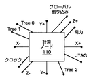
Blue Gene/Lシステムは、幾つかの通信ネットワークを介して通信する。図2は、BlueGene/Lシステム内の1つの計算ノードのI/O接続を示すブロック図である。65,536個の計算ノード110及び1,024個のI/Oプロセッサ170は、論理ツリー・ネットワーク及び論理的な3次元トーラス・ネットワークの両方に配列される。トーラス・ネットワークは、各計算ノード110がその6個の最近隣ノードと通信するように、計算ノードを3次元の格子構造状に接続する。図2では、トーラス・ネットワークは、当該ノードを6個の隣接ノードにそれぞれ接続するネットワーク接続X+、X−、Y+、Y−、Z+及びZ−によって例示される。一方、ツリー・ネットワークは、図2のTree0、Tree1及びTree2接続によって表される。当該ノードに接続される他の通信ネットワークは、1つのJTAGネットワーク及び1つのグローバル割り込みネットワークを含む。JTAGネットワークは、サービス・ノード140から図1の制御システム・ネットワーク150を介して、テスト及び制御用の通信を提供する。グローバル割り込みネットワークは、或るタスクの完了時に異なる処理段階に移動するように、複数の計算ノード上の同様のプロセスを同期化するためのソフトウェア・バリアを実装するために使用される。従って、このグローバル割り込みネットワークは、ノードの1つの区画で実行中のアプリケーションを始動、停止又は一時停止させるために使用することができる。さらに、各計算ノード110に対するクロック及び電力信号がある。
The Blue Gene / L system communicates via several communication networks. FIG. 2 is a block diagram showing the I / O connection of one compute node in the BlueGene / L system. 65,536
Blue Gene/Lシステムのトーラス相互接続は、論理的な3次元デカルト配列内で、各ノードをその6個の最近隣ノード(X+、X−、Y+、Y−、Z+及びZ−)に接続する。6個の最近隣ノードへの接続は、ノード・レベル及びミッドプレーン・レベルで行われる。各ミッドプレーンは、8×8×8ノードの配列である。ミッドプレーン内のノード配列の6個の面(X+、X−、Y+、Y−、Z+及びZ−)の各々は、8H8=64ノードのサイズを有する。6個の面の各々にある64ノードからの各トーラス・ネットワーク信号は、当該ミッドプレーンに接続されたリンク・カード(図示せず)を通して、隣接ミッドプレーン内の対応するノードに通信される。当該ミッドプレーンが、任意の次元において1ミッドプレーンの深さを有する区画内で使用される場合、各面の信号は、対向面上にある同じミッドプレーンの入力に戻されることがある。 The Blue Gene / L system torus interconnect connects each node to its six nearest neighbor nodes (X +, X-, Y +, Y-, Z + and Z-) in a logical three-dimensional Cartesian array. . Connections to the six nearest neighbors are made at the node level and midplane level. Each midplane is an 8 × 8 × 8 node array. Each of the six faces (X +, X-, Y +, Y-, Z + and Z-) of the node array in the midplane has a size of 8H8 = 64 nodes. Each torus network signal from 64 nodes on each of the six faces is communicated to the corresponding node in the adjacent midplane through a link card (not shown) connected to that midplane. If the midplane is used in a partition that has a depth of one midplane in any dimension, the signals for each plane may be returned to the same midplane input on the opposing plane.
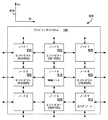
図3は、従来技術に従った、Blue Gene/Lシステム内の計算ノード110のブロック図である。計算ノード110は、ノード計算チップ112を有し、当該チップは、2つのプロセッサ310A、310Bを有する。各プロセッサ310A、310Bは、それぞれ処理コア312を有する。これらのプロセッサは、レベル3のメモリ・キャッシュ(L3キャッシュ)320及びスタティックRAM(SRAM)330に接続される。L3キャッシュ320からのデータは、ダブル・データ・レート(DDR)メモリ・コントローラ350を介して、DDR同期型ダイナミックRAM(SDRAM)340にロードされる。
FIG. 3 is a block diagram of a
SRAM330は、計算チップ112からのデータをIdoチップ180に通信する、JTAGインタフェース360に接続される。サービス・ノード(図1)は、Idoチップ180及び制御システム・ネットワーク150(図1)の一部であるイーサネット(登録商標)・リンクを通して、計算ノード110と通信する。Blue Gene/Lシステムでは、ノード・ボード120当たり1つのIdoチップが存在し、各ミッドプレーン132(図1)内のボード上に他のものが存在する。Idoチップ180は、信頼のおける100Mbpsの専用イーサネット(登録商標)制御ネットワーク上の生のUDPパケットを使用して、サービス・ノードからコマンドを受信する。Idoチップは、計算ノードとの通信のために、種々のシリアル・プロトコルをサポートする。JTAGプロトコルは、サービス・ノード140(図1)から計算 ノード110内のSRAM 330の任意のアドレスを対象とする読み取り及び書き込みを行うために使用され、またシステム初期化及びブート・プロセスのために使用される。
The
また、図3のノード計算チップ112は、ネットワーク・ハードウェア390を含む。ネットワーク・ハードウェア390は、トーラス・ネットワーク・ハードウェア392、ツリー・ネットワーク・ハードウェア394及びグローバル割り込みネットワーク・ハードウェア396を含む。前述のように、BlueGene/Lシステムのこれらのネットワークは、計算ノード110がシステム内の他のノードと通信するために使用される。ネットワーク・ハードウェア390は、計算ノード110がトーラス・ネットワークを介してデータ・パケットを受信し且つこれを受け渡すことを可能にする。ネットワーク・ハードウェア390は、ネットワーク・データのトラフィックを独立的に処理し、その結果、計算ノード110のプロセッサ310A、310Bは、トーラス・ネットワーク上を流れるデータの量によって負担を負わされることはない。他のノードを宛先として当該ノードをパススルーするネットワーク・データは、「カットスルー」トラフィックと呼ばれる。
3 includes
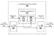
図4は、図3のトーラス・ネットワーク・ハードウェア392のブロック図である。トーラス・ネットワーク・ハードウェア392は、3つの主要なユニット、すなわちプロセッサ・インタフェース410、トーラス・センダ420及びトーラス・レシーバ430から成る、プロセッサ・インタフェース410は、先入れ先出し式のキューとして、プロセッサ注入FIFO412及びプロセッサ受信FIFO414から成る。これらのFIFOに対するアクセスは、プロセッサ310A、310B(図3)から2つの浮動小数点ユニット(FPU)レジスタ(図示せず)を介して行われる。すなわち、1対のFPUレジスタから128ビットのメモリ・マップド・ストアを介して、データがこれらのFIFOにロードされる。一方、これらのFIFOからデータが読み取られ、128ビット単位で、1対のFPUレジスタにロードされる。全部で8個あるプロセッサ注入FIFO412は、2グループに編成される。すなわち、一方のグループは、(ノード間オペレーティング・システム・メッセージ用の)2つの高優先順位FIFOから成り、他方のグループは、6個の通常優先順位FIFOから成る(それらのFIFOは最近隣ノード接続性のために十分である)。全てのFIFO内のパケットは、トーラス・ネットワーク上の任意の方向に送出することができる。プロセッサ受信FIFO414にも、FIFOの2つのグループがある。各グループは、7個のFIFOを含み、そのうち1つのFIFOは高優先順位用のものであり、6個のFIFOの各々は6入力方向の各々に専用される。具体的には、各レシーバとその対応する受信FIFOの間に、1つの専用バスがある。ストレージについては、全てのトーラスFIFOは、エラー検出及び訂正(ECC)によって保護されたSRAMチップを使用し、全ての内部データ経路はパリティについて検査される。
FIG. 4 is a block diagram of the
前述のトーラス・ネットワーク・ハードウェア392は、種々のトーラス・ネットワークを横切って、可変サイズのデータ・パケットを送信する。図5は、トーラス・ネットワーク・パケット510の1例を示す。Blue Gene/Lシステムでは、各パケット510は、n H 32バイトである。但し、n=1〜8個の「チャンク」である。例えば、MPI(Message Passing Interface)規格に準拠するメッセージは、関連する1つ又は両方のプロセッサ310A、310B(図3)上で実行中のソフトウェアによって構築され、送信され且つ受信される、多数のパケットから成ることがある。各パケットの最初の8バイトは、パケット・ヘッダ512である。パケット・ヘッダ512は、リンク・レベルのプロトコル情報(例えば、シーケンス番号)と、宛先を含む経路指定情報と、仮想チャンネル及びサイズと、伝送中のヘッダ・データの破損を検出する、バイト幅の巡回冗長検査(CRC)514とを保持する。また、パケット・ヘッダ512は、後述するヒント・ビット516を保持する。
The aforementioned
パケット・ヘッダ512の後には、多数のデータ・バイト518が保持される。さらに、各パケットには、1バイトの有効性標識520とともに、24ビットのCRCが付加される。有効性標識が必要であるのは、パケットが完全に受信される前にその転送が開始されることがあるためである。このCRCは、各パケットが各リンクを介して送信される際に、当該各パケットの検査を可能にする。タイムアウト機構は、破損パケットを再送するために使用される。8ビットのパケット・ヘッダCRCを使用することは、パケット・ヘッダ・エラーの早期検出を可能にする最適化である。というのは、ヘッダCRCが、完全なパケットCRC内に含まれるからである。
A number of
前述のように、ヘッダ512は、6つの「ヒント」ビット516を保持する。ヒント・ビット516は、トーラス・ネットワークの3次元内でパケットを経路指定することができる方向を指示する。ヒント・ビット516は、XYZの順序で、X+ X− Y+ Y− Z+ Z−のように定義される。例えば、100100のヒント・ビットは、当該パケットをX+及びY−方向に経路指定することができることを意味する。X+又はX−ヒント・ビットの何れか一方を設定することができるが、両方を設定することはできない。というのは、設定された1つのビットは、その次元内でパケットを送信すべき方向を指示するからである。デフォルトは、パケットを任意の方向に送信できることを指示するように、全てのヒント・ビットを設定解除又はゼロに設定することであろう。
As described above, the
一般に、トーラス・ネットワーク内では、ノード間をデータが流れる次元順序が存在する。本明細書で開示する複数の例では、その次元順序がXYZであると仮定するが、他の順序も使用することができる。次元順序がXYZであるという意味は、最初に、データが1つのノードからX次元内で流れ、次に、Y次元内で幾つかのノードを通り、次に、Z次元内で流れるというものである。XYZヒント・ビットは、XYZ次元内の経路指定のためにそれぞれ使用される。 In general, in a torus network, there is a dimensional order in which data flows between nodes. The examples disclosed herein assume that the dimensional order is XYZ, but other orders can also be used. The meaning that the dimensional order is XYZ is that data first flows from one node in the X dimension, then passes through several nodes in the Y dimension, and then flows in the Z dimension. is there. The XYZ hint bits are each used for routing within the XYZ dimension.
各ノードは、トーラス機能(図示せず)を制御する、ソフトウェアで構成可能な1組のレジスタを維持する。例えば、1組のレジスタは、その隣接ノードの座標を保持する。ヒント・ビットがゼロに設定されるのは、1つのパケットが1つのノードを1つの方向に離れ、そして隣接ノード座標レジスタによって決定されるように、当該パケットがその次元内のその宛先に到着するような場合である。ヒント・ビットは、ヘッダ内で早期に現れ、その結果、調停を効率的にパイプライン化することができる。ヒント・ビットは、ソフトウェア又はハードウェアの何れかによって初期化することができる。ハードウェアによって初期化される場合、適切な方向を決定するために、1次元当たり1組2つのレジスタが使用される。これらのレジスタは、最小ホップ経路指定を提供するように構成することができる。経路指定を完全に行うためには、ヒント・ビット及び仮想チャンネルを調べることが必要である。すなわち、経路指定テーブルは、存在しない。パケットは、動的に又は決定論的な次元順序(XYZ)で、経路指定することができる。すなわち、パケットは、他のトラフィックに基づいて最小輻輳の経路を辿るか、又は固定経路上で経路指定することができる。2地点間パケットのほかに、ヘッダ内の1つのビットを設定することにより、1つのパケットを任意のデカルト次元内でブロードキャストさせ且つこれを各ノードで受信させることができる。後述するように、ソフトウェアは、ヒント・ビットを適切に設定することにより、「デッド」ノード又はリンクを回避することができる。3つまでの非共線型(noncolinear)障害ノードが存在する場合には、完全な接続性を維持することができる。 Each node maintains a set of software configurable registers that control a torus function (not shown). For example, a set of registers holds the coordinates of its adjacent nodes. The hint bit is set to zero because one packet leaves one node in one direction and arrives at its destination in that dimension, as determined by the neighbor node coordinate register. This is the case. Hint bits appear early in the header, so that arbitration can be efficiently pipelined. The hint bits can be initialized by either software or hardware. When initialized by hardware, a set of two registers per dimension is used to determine the appropriate direction. These registers can be configured to provide minimum hop routing. In order to fully route, it is necessary to examine hint bits and virtual channels. That is, there is no routing table. Packets can be routed dynamically or in deterministic dimension order (XYZ). That is, the packet can follow the path of least congestion based on other traffic or be routed on a fixed path. In addition to point-to-point packets, one bit in the header can be set to broadcast one packet in any Cartesian dimension and receive it at each node. As described below, software can avoid “dead” nodes or links by setting the hint bits appropriately. Full connectivity can be maintained if there are up to three noncolinear fault nodes.
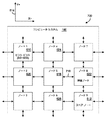
図6は、ノード・トラフィックを動的に再経路指定する1つの例を示すために、図1の超並列コンピュータ・システムの部分600を表すブロック図である。この部分600は、ノード1 610〜ノード9 612と表記した9個のノードを例示する。図面の内容を簡潔にするために、図6は、X次元及びY次元内のノードのみを示しているが、当該コンピュータ・システムは、Z次元内に位置するノードも有することを理解されたい。X次元及びY次元は、XY軸614によって示される通りである。この例については、アプリケーションがノード1 610〜ノード8 622上で実行中であるものと仮定する。障害又は潜在的な障害がノード5618上で検出される場合、アプリケーションが中断又は一時停止され、そしてFIFO内の全てのネットワーク・トラフィックがクリアされるまで待機することにより、ネットワークが休止される。次に、障害ノード5 618上のアプリケーションは、スペア・ノード(ノード9 612)に移動される。次に、障害ノード5618を通してデータを移動させる必要がある各ノードは、更新済みの問題リスト(図1の144)を全てのノード又は少なくとも影響を受けるノードに送信することにより、障害ノード5618を回避するように更新される。
FIG. 6 is a block diagram illustrating a
これらのノードは、更新済みの問題リストを使用して、データが障害ノード又は障害ネットワークを迂回して経路指定されることを保証する。次に、データが障害ノード5 618を迂回して経路指定されるように、各ノードから送信されるデータ・パケット内に適切なヒント・ビットが設定される。図6の例では、ノード2 620からのデータ・パケットは、X−用に設定されたヒント・ビットを有するから、X−方向に進行してノード8 622に至り、その結果、障害ノード5 618を回避するであろう。同様に、ノード8 622からのデータ・パケットは、X+用に設定されたヒント・ビットを有するから、X+方向に進行してノード2 620に至る。また、ノード4 624からのデータ・パケットは、Y+用に設定されたヒント・ビットを有するから、Y+方向に進行してノード6 626に至り、その結果、障害ノード5 618を回避するであろう。これに対し、ノード6 626からのデータ・パケットは、Y−用に設定されたヒント・ビットを有するから、Y−方向に進行してノード4 624に至る。
These nodes use the updated problem list to ensure that data is routed around the failed node or network. The appropriate hint bit is then set in the data packet sent from each node so that the data is routed around the failed node 5 618. In the example of FIG. 6, the data packet from
図7は、ノード・トラフィックを動的に再経路指定する他の例を示すために、図1の超並列コンピュータ・システムの部分700を表すブロック図である。この例は、非隣接ノードについてのヒント・ビットの使用方法を示す。図6の例と同様に、この部分700は、ノード1 610〜ノード9 612と表記した9個のノードを例示する。この例では、障害又は潜在的な障害がノード8 622上で検出される。アプリケーションが一時停止され、ネットワークが休止され、そして障害ノード8622上のアプリケーションがスペア・ノード(ノード9612)に移動される。次に、図6の例と同様に、障害ノード8 622を通してデータを移動させる必要がある各ノードは、更新済みの問題リスト(図1の144)を影響を受けるノードに送信することにより、障害ノード8622を回避するように更新される。次に、データが障害ノード8 622を迂回して経路指定されることを保証するように、ヒント・ビットが設定される。図7の例では、ノード1 610からのデータ・パケットは、障害ノード8 622がX方向に存在しないという理由で、X方向用に設定されたヒント・ビットを有しないであろう。しかし、ノード1 610は、パケットがY+方向に進行するように、設定済みのY+ヒント・ビットを有するであろう。ノード1 610からのパケットがノード7628に到着し且つY次元内の進行を開始する場合、当該パケットは、設定済みのY+ヒント・ビットによって指示されるようにY+方向のノード9612に進行し、その結果、障害ノード8622を回避するであろう。
FIG. 7 is a block diagram illustrating a
前述のように、ヒント・ビットは、輻輳ネットワークを迂回して動的に経路指定するためにも使用することができる。1例として、図7のノード8 622とノード5 618との間のネットワーク710を検討する。もし、ネットワーク710が、ネットワーク監視機構(図1の142)によって輻輳ネットワークとして標識付けされるならば、障害ノード8 622を迂回して経路指定するためにヒント・ビットを使用する前述の方法と同様に、このネットワークを迂回して動的に経路指定するためにヒント・ビットを使用することができる。代替的に、カットスルー・トラフィックによって、ノードの負担が過度に大きくなることがある。例えば、ネットワーク監視機構が、ノード8 622を通るカットスルー・トラフィックに起因して、ノード8 622が過負荷であると決定した場合、ノード8 622上で実行していたプロセス又はアプリケーションに関するカットスルー・トラフィック負荷を軽減するために、ノード8622上のプロセスは、利用可能な交換ノードに動的に再経路指定される。
As mentioned above, hint bits can also be used to dynamically route around congested networks. As an example, consider the
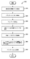
図8は、並列コンピュータ・システム内の障害ノードのプロセスを動的に再経路指定するために、ノードを監視するための方法800を示す。この方法は、サービス・ノード上のソフトウェアによって実施されるが、必要とされる情報を集めるためにソフトウェア及びハードウェアの一方又は両方を必要とすることがある。最初に、ネットワークを監視し(ステップ810)、ネットワーク・ホットスポットを問題リスト内に記録する(ステップ820)。次に、ノードを監視し(ステップ830)、障害ノード又は障害を生じる可能性があるノードを問題リスト内に記録する(ステップ840)。その後、この方法が終了する。
FIG. 8 illustrates a
図9は、並列コンピュータ・システム内の障害ノードのプロセスを動的に再経路指定するための方法900を示す。好ましくは、この方法は、並列コンピュータ・システムの各ノード上のソフトウェア及びハードウェアの一方又は両方によって実施される。最初に、サービス・ノード上のネットワーク監視機構によって送信され且つ回避すべきノード又はネットワークを保持する、更新済みの問題リストを検出する(ステップ910)。次に、障害ノードを有する並列システムの区画で実行中のアプリケーションを一時的に停止する(ステップ920)。次に、トーラス・ネットワーク・ハードウェアのFIFOがそれらのメッセージの送信を完了するまで待機することにより、ネットワークを休止する(ステップ930)。次に、ネットワーク用の交換ノード又は代替経路を見つけた後(ステップ940)、障害ノードのプロセスを交換ノードに移動させる(ステップ950)。次に、障害ノード又は障害ネットワークを通してネットワーク・トラフィックを送信するであろうノードに対し、ヒント・ビットを使用して、当該障害ノードを分離し且つ当該障害ノード又は輻輳ネットワークを迂回してネットワーク・トラフィックを経路指定するように通知する(ステップ960)。次に、アプリケーションをその一時的に停止した点から再開することができる(ステップ970)。その後、この方法が終了する。
FIG. 9 illustrates a
本明細書は、超並列コンピュータ・システム上で実行中のアプリケーションを再始動することなく、ヒント・ビットを使用して、超並列コンピュータ・システムの計算ノード上のノード・トラフィックを動的に再経路指定するための装置及び方法を開示する。ノード・トラフィックを動的に再経路指定すると、故障時間の量を著しく減少させることができ、その結果、コンピュータ・システムの効率を向上させることができる。本方法は、コンピュータ・ソフトウェアの形態で実施することができる。 The present specification uses hint bits to dynamically reroute node traffic on a compute node of a massively parallel computer system without restarting applications running on the massively parallel computer system. An apparatus and method for designating is disclosed. Dynamic rerouting of node traffic can significantly reduce the amount of failure time and, as a result, improve the efficiency of the computer system. The method can be implemented in the form of computer software.
当業者には明らかなように、本発明の範囲内で多数の変形が可能である。本発明は特定の実施形態を参照して説明されたが、本発明の精神及び範囲から逸脱することなく、形式及び詳細に関する種々の変更を施し得ることは明らかであろう。 As will be apparent to those skilled in the art, many variations are possible within the scope of the present invention. Although the invention has been described with reference to particular embodiments, it will be apparent that various changes can be made in form and detail without departing from the spirit and scope of the invention.
100・・・超並列コンピュータ・システム
110・・・計算ノード
140・・・サービス・ノード
142・・・ノード/ネットワーク監視機構
144・・・問題リスト
150・・・制御システム・ネットワーク
392・・・トーラス・ネットワーク・ハードウェア
394・・・ツリー・ネットワーク・ハードウェア
396・・・グローバル割り込みネットワーク・ハードウェア
510・・・トーラス・ネットワーク・パケット
512・・・パケット・ヘッダ
516・・・ヒント・ビット
DESCRIPTION OF
Claims (17)
論理的な3次元デカルト配列内で、各ノードをその6個の最近隣ノード(X+、X−、Y+、Y−、Z+及びZ−)に接続するトーラス・ネットワークによって接続された複数のノードと、
前記並列コンピュータ・システムの前記複数のノード及びネットワーク接続を監視し且つノード及びネットワーク接続の問題リストを作成するノード/ネットワーク監視機構とを備え、
前記複数のノードの少なくともいずれかは、前記問題リスト内のノード及びネットワーク接続を回避するように、各ノードから送信されるデータ・パケット内に6個の最近隣ノード(X+、X−、Y+、Y−、Z+及びZ−)用に設定されたヒント・ビットを使用して、データ・パケットを障害ノード又は障害ネットワーク接続を迂回して1つ以上の前記ネットワーク接続を介して動的に経路指定するものである、並列コンピュータ・システム。 A parallel computer system,
A plurality of nodes connected by a torus network connecting each node to its six nearest neighbor nodes (X +, X-, Y +, Y-, Z + and Z-) in a logical three-dimensional Cartesian array; ,
A node / network monitoring mechanism that monitors the plurality of nodes and network connections of the parallel computer system and creates a problem list of nodes and network connections;
At least one of the plurality of nodes includes six nearest neighbor nodes (X +, X-, Y +, in a data packet transmitted from each node so as to avoid nodes and network connections in the problem list. Using hint bits set for Y-, Z + and Z-), data packets are dynamically routed through one or more said network connections , bypassing the failed node or network connection A parallel computer system.
問題について前記複数の計算ノード及びネットワーク接続を監視し且つ障害ノード及び障害ネットワーク接続を問題リスト内で特定するステップと、
更新済みの問題リストを検出するステップと、
アプリケーションを実行中の計算ノードの実行を一時的に停止させるステップと、
前記問題リスト内のノード又はネットワーク接続を分離するように、各ノードから送信されるデータ・パケット内に6個の最近隣ノード(X+、X−、Y+、Y−、Z+及びZ−)用に設定されたヒント・ビットを設定するステップと、
一時的に停止させていた前記アプリケーションの実行を再開するステップとを含む、コンピュータ実装方法。 By using hint bits, you can use hint bits in a logical 3D Cartesian array in the parallel computer system without restarting the application running on the parallel computer system. Dynamically node traffic on multiple compute nodes connected by a torus network connecting each node to its 6 nearest neighbor nodes (X +, X-, Y +, Y-, Z + and Z-) A computer-implemented method for rerouting comprising:
Monitoring the plurality of compute nodes and network connections for problems and identifying failed nodes and failed network connections in a problem list;
Detecting an updated problem list;
Temporarily stopping the execution of the compute node running the application;
For the six nearest nodes (X +, X-, Y +, Y-, Z + and Z-) in the data packet sent from each node to isolate the nodes or network connections in the problem list Setting a set hint bit; and
Resuming the execution of the application that has been temporarily stopped.
トラフィックを当該輻輳ネットワークを迂回して経路指定するように少なくとも1つのヒント・ビットを設定するステップとをさらに含む、請求項6ないし請求項10の何れか1項に記載のコンピュータ実装方法。 Detecting a congestion network for the compute nodes;
11. The computer-implemented method of any one of claims 6 to 10, further comprising setting at least one hint bit to route traffic around the congested network.
コンピュータを、
前記複数のノード及びネットワーク接続を監視し且つノード及びネットワーク接続の問題リストを作成するノード/ネットワーク監視機構として機能させ、そして
前記問題リスト内のノード及びネットワーク接続を回避するように、各ノードから送信されるデータ・パケット内に6個の最近隣ノード(X+、X−、Y+、Y−、Z+及びZ−)用に設定されたヒント・ビットを使用して、データ・パケットを前記ネットワーク接続を介して動的に経路指定するノード経路指定機構として機能させるためのコンピュータ・プログラム。 Connected by a network connection that makes up a torus network that connects each node to its six nearest neighbor nodes (X +, X-, Y +, Y-, Z + and Z-) within a logical three-dimensional Cartesian array. In a parallel computer system having a plurality of nodes,
Computer
Acts as a node / network monitoring mechanism that monitors the plurality of nodes and network connections and creates a problem list of nodes and network connections, and transmits from each node to avoid nodes and network connections in the problem list Data packets are routed to the network connection using hint bits set for the six nearest neighbor nodes (X +, X-, Y +, Y-, Z + and Z-) A computer program for functioning as a node routing mechanism that dynamically routes through a network.
Applications Claiming Priority (3)
| Application Number | Priority Date | Filing Date | Title |
|---|---|---|---|
| US11/736,811 US7644254B2 (en) | 2007-04-18 | 2007-04-18 | Routing data packets with hint bit for each six orthogonal directions in three dimensional torus computer system set to avoid nodes in problem list |
| US11/736,811 | 2007-04-18 | ||
| PCT/EP2008/053377 WO2008128836A2 (en) | 2007-04-18 | 2008-03-20 | Dynamically rerouting node traffic on a parallel computer system |
Publications (2)
| Publication Number | Publication Date |
|---|---|
| JP2010525433A JP2010525433A (en) | 2010-07-22 |
| JP5285690B2 true JP5285690B2 (en) | 2013-09-11 |
Family
ID=39739647
Family Applications (1)
| Application Number | Title | Priority Date | Filing Date |
|---|---|---|---|
| JP2010503440A Expired - Fee Related JP5285690B2 (en) | 2007-04-18 | 2008-03-20 | Parallel computer system, computer-implemented method, computer-readable recording medium and computer program for dynamically rerouting node traffic on parallel computer system |
Country Status (7)
| Country | Link |
|---|---|
| US (1) | US7644254B2 (en) |
| EP (1) | EP2156291A2 (en) |
| JP (1) | JP5285690B2 (en) |
| KR (1) | KR20090122209A (en) |
| CN (1) | CN101663649B (en) |
| TW (1) | TW200907702A (en) |
| WO (1) | WO2008128836A2 (en) |
Families Citing this family (22)
| Publication number | Priority date | Publication date | Assignee | Title |
|---|---|---|---|---|
| GB2462492B (en) * | 2008-08-14 | 2012-08-15 | Gnodal Ltd | A multi-path network |
| WO2010060923A1 (en) * | 2008-11-26 | 2010-06-03 | Danmarks Tekniske Universitet | Biologically inspired hardware cell architecture |
| WO2010093933A1 (en) * | 2009-02-13 | 2010-08-19 | Ab Initio Technology Llc | Communicating with data storage systems |
| US8479215B2 (en) * | 2009-08-18 | 2013-07-02 | International Business Machines Corporation | Decentralized load distribution to reduce power and/or cooling costs in an event-driven system |
| US9135215B1 (en) * | 2009-09-21 | 2015-09-15 | Tilera Corporation | Route prediction in packet switched networks |
| US8103910B2 (en) * | 2009-11-13 | 2012-01-24 | International Business Machines Corporation | Local rollback for fault-tolerance in parallel computing systems |
| US8359404B2 (en) * | 2010-01-08 | 2013-01-22 | International Business Machines Corporation | Zone routing in a torus network |
| US10845962B2 (en) * | 2009-12-14 | 2020-11-24 | Ab Initio Technology Llc | Specifying user interface elements |
| US8559307B2 (en) * | 2009-12-28 | 2013-10-15 | Empire Technology Development Llc | Routing packets in on-chip networks |
| US8140889B2 (en) * | 2010-08-23 | 2012-03-20 | International Business Machines Corporation | Dynamically reassigning a connected node to a block of compute nodes for re-launching a failed job |
| JP5750963B2 (en) * | 2011-03-22 | 2015-07-22 | 富士通株式会社 | Parallel computer system, control apparatus, parallel computer system control method, and parallel computer system control program |
| US9811233B2 (en) | 2013-02-12 | 2017-11-07 | Ab Initio Technology Llc | Building applications for configuring processes |
| US9424229B2 (en) | 2013-02-13 | 2016-08-23 | Advanced Micro Devices, Inc. | Parallel torus network interconnect |
| US10996989B2 (en) * | 2016-06-13 | 2021-05-04 | International Business Machines Corporation | Flexible optimized data handling in systems with multiple memories |
| CN106130895B (en) * | 2016-08-18 | 2019-11-15 | 中国联合网络通信集团有限公司 | The heavy route method and device of SDN network failure |
| US11423083B2 (en) | 2017-10-27 | 2022-08-23 | Ab Initio Technology Llc | Transforming a specification into a persistent computer program |
| TWI686696B (en) | 2018-08-14 | 2020-03-01 | 財團法人工業技術研究院 | Compute node, failure detection method thereof and cloud data processing system |
| JP7167687B2 (en) * | 2018-12-18 | 2022-11-09 | 富士通株式会社 | Information processing device, information processing method and information processing program |
| US11057265B2 (en) * | 2019-06-27 | 2021-07-06 | Cerner Innovation, Inc. | Path check insight |
| JP2021135983A (en) * | 2020-02-28 | 2021-09-13 | 京セラドキュメントソリューションズ株式会社 | Data cooperation system and data collection system |
| CN113364603B (en) * | 2020-03-06 | 2023-05-02 | 华为技术有限公司 | Fault recovery method of ring network and physical node |
| CN114860511A (en) * | 2022-04-29 | 2022-08-05 | 上海阵量智能科技有限公司 | Data processing method and device, chip, electronic equipment and medium |
Family Cites Families (13)
| Publication number | Priority date | Publication date | Assignee | Title |
|---|---|---|---|---|
| AU3059689A (en) * | 1988-02-04 | 1989-08-25 | City University, The | Improvements in or relating to data handling arrays |
| US5495426A (en) * | 1994-01-26 | 1996-02-27 | Waclawsky; John G. | Inband directed routing for load balancing and load distribution in a data communication network |
| JPH07239835A (en) * | 1994-02-25 | 1995-09-12 | Hitachi Ltd | In-network data transfer control system for parallel computer |
| US6865149B1 (en) * | 2000-03-03 | 2005-03-08 | Luminous Networks, Inc. | Dynamically allocated ring protection and restoration technique |
| US7729261B2 (en) * | 2004-08-10 | 2010-06-01 | Alcatel Lucent | Forwarding of network traffic in respect of differentiated restricted transit network nodes |
| US20070053283A1 (en) * | 2005-09-06 | 2007-03-08 | International Business Machines Corporation | Correlation and consolidation of link events to facilitate updating of status of source-destination routes in a multi-path network |
| US7835284B2 (en) | 2006-10-06 | 2010-11-16 | International Business Machines Corporation | Method and apparatus for routing data in an inter-nodal communications lattice of a massively parallel computer system by routing through transporter nodes |
| US8031614B2 (en) | 2006-10-06 | 2011-10-04 | International Business Machines Corporation | Method and apparatus for routing data in an inter-nodal communications lattice of a massively parallel computer system by dynamic global mapping of contended links |
| US7680048B2 (en) | 2006-10-06 | 2010-03-16 | International Business Machiens Corporation | Method and apparatus for routing data in an inter-nodal communications lattice of a massively parallel computer system by dynamically adjusting local routing strategies |
| US7839786B2 (en) | 2006-10-06 | 2010-11-23 | International Business Machines Corporation | Method and apparatus for routing data in an inter-nodal communications lattice of a massively parallel computer system by semi-randomly varying routing policies for different packets |
| US20080178177A1 (en) | 2007-01-19 | 2008-07-24 | Charles Jens Archer | Method and Apparatus for Operating a Massively Parallel Computer System to Utilize Idle Processor Capability at Process Synchronization Points |
| US7631169B2 (en) | 2007-02-02 | 2009-12-08 | International Business Machines Corporation | Fault recovery on a massively parallel computer system to handle node failures without ending an executing job |
| US7706275B2 (en) | 2007-02-07 | 2010-04-27 | International Business Machines Corporation | Method and apparatus for routing data in an inter-nodal communications lattice of a massively parallel computer system by employing bandwidth shells at areas of overutilization |
-
2007
- 2007-04-18 US US11/736,811 patent/US7644254B2/en not_active Expired - Fee Related
-
2008
- 2008-03-20 JP JP2010503440A patent/JP5285690B2/en not_active Expired - Fee Related
- 2008-03-20 CN CN2008800124505A patent/CN101663649B/en not_active Expired - Fee Related
- 2008-03-20 KR KR1020097017336A patent/KR20090122209A/en active IP Right Grant
- 2008-03-20 EP EP08718093A patent/EP2156291A2/en not_active Withdrawn
- 2008-03-20 WO PCT/EP2008/053377 patent/WO2008128836A2/en active Application Filing
- 2008-04-15 TW TW097113660A patent/TW200907702A/en unknown
Also Published As
| Publication number | Publication date |
|---|---|
| CN101663649B (en) | 2012-07-18 |
| US7644254B2 (en) | 2010-01-05 |
| TW200907702A (en) | 2009-02-16 |
| WO2008128836A2 (en) | 2008-10-30 |
| CN101663649A (en) | 2010-03-03 |
| KR20090122209A (en) | 2009-11-26 |
| JP2010525433A (en) | 2010-07-22 |
| WO2008128836A3 (en) | 2008-12-18 |
| US20080263386A1 (en) | 2008-10-23 |
| EP2156291A2 (en) | 2010-02-24 |
Similar Documents
| Publication | Publication Date | Title |
|---|---|---|
| JP5285690B2 (en) | Parallel computer system, computer-implemented method, computer-readable recording medium and computer program for dynamically rerouting node traffic on parallel computer system | |
| JP5285061B2 (en) | Parallel computer system, computer-implemented method, product and computer program for failure recovery in parallel computer system | |
| JP3709795B2 (en) | Computer system and method for communication between modules in the computer system | |
| US20190260504A1 (en) | Systems and methods for maintaining network-on-chip (noc) safety and reliability | |
| CN101589370B (en) | A parallel computer system and fault recovery method therefor | |
| US9244759B2 (en) | Error recovery to enable error-free message transfer between nodes of a computer network | |
| US9256500B2 (en) | Physical domain error isolation and recovery in a multi-domain system | |
| JP2004062535A (en) | Method of dealing with failure for multiprocessor system, multiprocessor system and node | |
| WO2017118080A1 (en) | Heat removing and heat adding method and device for central processing unit (cpu) | |
| CN102629912B (en) | Fault-tolerant deflection routing method and device for bufferless network-on-chip | |
| JP2004326775A (en) | Mechanism for fru fault isolation in distributed node environment | |
| JP5307151B2 (en) | Changing system routing information in link-based systems | |
| JP2008165531A (en) | Method for failover (restoration) of defective node in computer system having a plurality of nodes | |
| US7656789B2 (en) | Method, system and storage medium for redundant input/output access | |
| US7930584B2 (en) | Cell boundary fault detection system | |
| US7573810B2 (en) | Avoiding deadlocks in performing failovers in communications environments | |
| Marcon et al. | Phoenix NoC: A distributed fault tolerant architecture | |
| US7826379B2 (en) | All-to-all sequenced fault detection system | |
| US20230261971A1 (en) | Robust Vertical Redundancy Of Networking Devices | |
| CN108632142B (en) | Routing management method and device of node controller | |
| JPH1027115A (en) | Fault information sampling circuit for computer system | |
| US20190121573A1 (en) | Storage system and storage control apparatus | |
| WO2023165743A1 (en) | Reset of a multi-node system | |
| Sadawarti et al. | Fault-tolerant routing in unique-path multistage interconnection networks | |
| JP2021158563A (en) | Device and method for data processing |
Legal Events
| Date | Code | Title | Description |
|---|---|---|---|
| A621 | Written request for application examination |
Free format text: JAPANESE INTERMEDIATE CODE: A621 Effective date: 20101029 |
|
| A977 | Report on retrieval |
Free format text: JAPANESE INTERMEDIATE CODE: A971007 Effective date: 20130121 |
|
| A131 | Notification of reasons for refusal |
Free format text: JAPANESE INTERMEDIATE CODE: A131 Effective date: 20130205 |
|
| A521 | Request for written amendment filed |
Free format text: JAPANESE INTERMEDIATE CODE: A523 Effective date: 20130311 |
|
| A131 | Notification of reasons for refusal |
Free format text: JAPANESE INTERMEDIATE CODE: A131 Effective date: 20130416 |
|
| A521 | Request for written amendment filed |
Free format text: JAPANESE INTERMEDIATE CODE: A523 Effective date: 20130424 |
|
| A01 | Written decision to grant a patent or to grant a registration (utility model) |
Free format text: JAPANESE INTERMEDIATE CODE: A01 Effective date: 20130514 |
|
| A61 | First payment of annual fees (during grant procedure) |
Free format text: JAPANESE INTERMEDIATE CODE: A61 Effective date: 20130531 |
|
| LAPS | Cancellation because of no payment of annual fees |