JP5284463B2 - Liquid-filled vibration isolator - Google Patents
Liquid-filled vibration isolator Download PDFInfo
- Publication number
- JP5284463B2 JP5284463B2 JP2011509199A JP2011509199A JP5284463B2 JP 5284463 B2 JP5284463 B2 JP 5284463B2 JP 2011509199 A JP2011509199 A JP 2011509199A JP 2011509199 A JP2011509199 A JP 2011509199A JP 5284463 B2 JP5284463 B2 JP 5284463B2
- Authority
- JP
- Japan
- Prior art keywords
- elastic wall
- liquid
- fixture
- elastic
- liquid chamber
- Prior art date
- Legal status (The legal status is an assumption and is not a legal conclusion. Google has not performed a legal analysis and makes no representation as to the accuracy of the status listed.)
- Active
Links
Images


Classifications
-
- F—MECHANICAL ENGINEERING; LIGHTING; HEATING; WEAPONS; BLASTING
- F16—ENGINEERING ELEMENTS AND UNITS; GENERAL MEASURES FOR PRODUCING AND MAINTAINING EFFECTIVE FUNCTIONING OF MACHINES OR INSTALLATIONS; THERMAL INSULATION IN GENERAL
- F16F—SPRINGS; SHOCK-ABSORBERS; MEANS FOR DAMPING VIBRATION
- F16F13/00—Units comprising springs of the non-fluid type as well as vibration-dampers, shock-absorbers, or fluid springs
- F16F13/04—Units comprising springs of the non-fluid type as well as vibration-dampers, shock-absorbers, or fluid springs comprising both a plastics spring and a damper, e.g. a friction damper
- F16F13/06—Units comprising springs of the non-fluid type as well as vibration-dampers, shock-absorbers, or fluid springs comprising both a plastics spring and a damper, e.g. a friction damper the damper being a fluid damper, e.g. the plastics spring not forming a part of the wall of the fluid chamber of the damper
- F16F13/08—Units comprising springs of the non-fluid type as well as vibration-dampers, shock-absorbers, or fluid springs comprising both a plastics spring and a damper, e.g. a friction damper the damper being a fluid damper, e.g. the plastics spring not forming a part of the wall of the fluid chamber of the damper the plastics spring forming at least a part of the wall of the fluid chamber of the damper
- F16F13/10—Units comprising springs of the non-fluid type as well as vibration-dampers, shock-absorbers, or fluid springs comprising both a plastics spring and a damper, e.g. a friction damper the damper being a fluid damper, e.g. the plastics spring not forming a part of the wall of the fluid chamber of the damper the plastics spring forming at least a part of the wall of the fluid chamber of the damper the wall being at least in part formed by a flexible membrane or the like
- F16F13/105—Units comprising springs of the non-fluid type as well as vibration-dampers, shock-absorbers, or fluid springs comprising both a plastics spring and a damper, e.g. a friction damper the damper being a fluid damper, e.g. the plastics spring not forming a part of the wall of the fluid chamber of the damper the plastics spring forming at least a part of the wall of the fluid chamber of the damper the wall being at least in part formed by a flexible membrane or the like characterised by features of partitions between two working chambers
- F16F13/106—Design of constituent elastomeric parts, e.g. decoupling valve elements, or of immediate abutments therefor, e.g. cages
Landscapes
- Engineering & Computer Science (AREA)
- General Engineering & Computer Science (AREA)
- Mechanical Engineering (AREA)
- Combined Devices Of Dampers And Springs (AREA)
Abstract
Description
本発明は、液封入式防振装置に関するものである。 The present invention relates to a liquid-filled vibration isolator.
液封入式防振装置は一般に、第1取付け具と、筒状の第2取付け具と、前記第1取付け具と第2取付け具を連結するゴム状弾性材からなる防振基体と、前記第2取付け具に取付けられて防振基体との間に液体封入室を形成するゴム膜からなるダイヤフラムと、前記液体封入室を防振基体側の第1液室とダイヤフラム側の第2液室に仕切る仕切り体と、これら第1液室と第2液室を連通させるオリフィス流路とを備えて構成されている。 The liquid-filled vibration isolator generally includes a first mounting tool, a cylindrical second mounting tool, a vibration-proof base made of a rubber-like elastic material that connects the first mounting tool and the second mounting tool, and the first mounting tool. (2) A diaphragm made of a rubber film which is attached to a fixture and forms a liquid sealing chamber between the vibration isolating substrate and the liquid sealing chamber as a first liquid chamber on the vibration isolating substrate side and a second liquid chamber on the diaphragm side. A partition body for partitioning and an orifice channel for communicating the first liquid chamber and the second liquid chamber are provided.
このような液封入式防振装置として、下記特許文献1には、第1液室と第2液室を仕切る仕切り体を次のように構成することが提案されている。すなわち、仕切り体は、環状のオリフィス形成部材と、その内周面間を塞ぐゴム状弾性材からなる弾性壁と、該弾性壁を貫通する連結部を介して互いに連結され前記弾性壁を軸芯方向で挟み込む一対の仕切り板、とからなり、該一対の仕切り板の軸芯方向における変位量が弾性壁によって規制されるように構成されている。 As such a liquid-filled vibration isolator, Patent Document 1 below proposes that a partition body for partitioning the first liquid chamber and the second liquid chamber is configured as follows. That is, the partition body is connected to each other via an annular orifice forming member, an elastic wall made of a rubber-like elastic material that closes between the inner peripheral surfaces thereof, and a connecting portion that penetrates the elastic wall, and the elastic wall serves as an axial core. A pair of partition plates sandwiched in the direction, and the displacement amount of the pair of partition plates in the axial direction is restricted by the elastic wall.
この液封入式防振装置であると、一対の仕切り板の変位量が弾性壁によって規制されるので、低周波数域での大振幅振動に対してオリフィス流路による液体流動効果によって振動を減衰しながら、高周波数域での微振幅振動に対して仕切り板の往復動による動ばね定数の低減によって振動を低減することができる。
上記のように、特許文献1に開示の構成であると、低周波数域での大振幅振動に対して減衰を十分確保しつつ、高周波数域での微振幅振動に対して低動ばね化を実現することができる。しかしながら、微振幅振動時における更なる低動ばね化の要請があり、特許文献1に開示の構成では、大振幅振動時の高減衰性能を確保したまま、上記要請に十分に応えることは困難であった。 As described above, with the configuration disclosed in Patent Document 1, a sufficient amount of damping is ensured for large amplitude vibrations in the low frequency range, while low dynamic springs are provided for fine amplitude vibrations in the high frequency range. Can be realized. However, there is a demand for further lower dynamic springs at the time of fine amplitude vibration, and with the configuration disclosed in Patent Document 1, it is difficult to sufficiently meet the above demand while ensuring high damping performance at the time of large amplitude vibration. there were.
本発明は、以上の点に鑑みてなされたものであり、大振幅振動時の高減衰性能を確保したまま、微振幅振動時の更なる低動ばね化を図ることができる液封入式防振装置を提供することを目的とする。 The present invention has been made in view of the above points, and is a liquid-filled type anti-vibration that can further reduce the dynamic spring during fine amplitude vibration while ensuring high damping performance during large amplitude vibration. An object is to provide an apparatus.
本発明に係る液封入式防振装置は、第1取付け具と、筒状の第2取付け具と、前記第1取付け具と前記第2取付け具を連結するゴム状弾性材からなる防振基体と、前記第2取付け具に取付けられて前記防振基体との間に液体封入室を形成するゴム状弾性膜からなるダイヤフラムと、前記液体封入室を前記防振基体側の第1液室と前記ダイヤフラム側の第2液室に仕切る仕切り体と、前記第1液室と第2液室を連通させるオリフィス流路と、を備えた液封入式防振装置であって、前記仕切り体が、前記第2取付け具の周壁部の内側に設けられて前記オリフィス流路を形成する環状のオリフィス形成部材と、前記オリフィス形成部材の内周面の間を塞ぐゴム状弾性材からなる弾性壁と、前記弾性壁の径方向中央部を貫通する連結部を介して互いに連結され、前記弾性壁を該弾性壁の軸芯方向で挟み込む一対の仕切り板と、からなることを基本構成とするものである。 The liquid-filled vibration isolator according to the present invention includes a first mounting tool, a cylindrical second mounting tool, and a vibration-proof base made of a rubber-like elastic material that connects the first mounting tool and the second mounting tool. A diaphragm made of a rubber-like elastic film that is attached to the second fixture and forms a liquid sealing chamber between the vibration isolating substrate and the first liquid chamber on the side of the vibration isolating substrate. A liquid-filled vibration isolator comprising: a partition body that partitions the second liquid chamber on the diaphragm side; and an orifice channel that communicates the first liquid chamber and the second liquid chamber, wherein the partition body includes: An annular orifice forming member that is provided inside the peripheral wall portion of the second fixture and forms the orifice flow path; and an elastic wall made of a rubber-like elastic material that blocks between the inner peripheral surfaces of the orifice forming member; The connecting portions passing through the radial center of the elastic wall It is binding, and the pair of partition plates which sandwich the elastic wall in the axial direction of the elastic wall, in that it consists of those having a basic configuration.
そして、本発明の第1の態様に係るものでは、前記一対の仕切り板の軸芯方向における変位量が前記弾性壁によって規制されるように構成されており、少なくとも一方の前記仕切り板に軸芯方向に貫通する貫通穴が前記連結部の径方向外方側に設けられている。 According to the first aspect of the present invention, the displacement amount in the axial direction of the pair of partition plates is configured to be regulated by the elastic wall, and at least one of the partition plates has an axial core. A through hole penetrating in the direction is provided on the radially outer side of the connecting portion.
また、本発明の第2の態様に係るものでは、前記一対の仕切り板の軸芯方向における変位量が前記弾性壁によって規制されるように構成されており、前記弾性壁の表裏少なくとも一方の壁面に凹部が設けられ、前記凹部を当該凹部の径方向外方側で前記第1液室又は第2液室に繋げるための径方向に延びる溝が前記仕切り板の板面又は前記弾性壁の壁面に設けられ、前記溝によって形成される前記仕切り板の板面と前記弾性壁の壁面との隙間を介して前記凹部内と前記第1液室又は第2液室とが液体流動可能に繋げられている。 According to the second aspect of the present invention, the amount of displacement of the pair of partition plates in the axial direction is restricted by the elastic wall, and at least one wall surface of the elastic wall A recess extending in the radial direction for connecting the recess to the first liquid chamber or the second liquid chamber on the radially outer side of the recess is a plate surface of the partition plate or a wall surface of the elastic wall The inside of the recess and the first liquid chamber or the second liquid chamber are connected to each other through a gap between a plate surface of the partition plate formed by the groove and a wall surface of the elastic wall so as to allow liquid flow. ing.
本発明の液封入式防振装置であると、低周波数域での大振幅振動に対しては、一対の仕切り板の変位量が弾性壁によって規制されることにより、オリフィス流路による液体流動効果によって高減衰性能を確保することができる。高周波数域での微振幅振動に対しては、一対の仕切り板が往復動することにより、動ばね定数の低減によって振動を低減することができる。 With the liquid-filled vibration isolator of the present invention, the liquid flow effect by the orifice flow path is controlled by the elastic wall with respect to the large amplitude vibration in the low frequency range by restricting the amount of displacement of the pair of partition plates. Therefore, high damping performance can be ensured. For fine amplitude vibration in a high frequency range, the vibration can be reduced by reducing the dynamic spring constant by reciprocating the pair of partition plates.
そして、上記第1の態様であると、微振幅振動の入力時に、仕切り板が微振幅振動することによって、仕切り板に設けられた軸芯方向に貫通する貫通穴内に液体流動が生じ、これにより当該貫通穴を高周波のオリフィス流路として作用させることができる。そのため、特定の周波数帯で液共振を発生させることができ、当該周波数帯の動ばね定数を低減することができる。 And when it is the said 1st aspect, when a fine amplitude vibration is input, a liquid flow arises in the through-hole penetrated in the axial direction provided in the partition plate by a fine amplitude vibration, and thereby The through hole can act as a high-frequency orifice channel. Therefore, liquid resonance can be generated in a specific frequency band, and the dynamic spring constant of the frequency band can be reduced.
また、上記第2の態様であると、微振幅振動時に、仕切り板又は弾性壁に設けた溝によって形成された隙間を、高周波のオリフィス流路として作用させることができる。そのため、第1の態様と同様に、特定の周波数帯で液共振を発生させることができ、当該周波数帯の動ばね定数を低減することができる。また、この態様では、大振幅振動時には、仕切り板が軸芯方向に変位することで上記隙間を仕切り板によって塞ぐことが可能となり、本来のオリフィス流路による高減衰性能の確保に有利である。 In the second aspect, the gap formed by the groove provided in the partition plate or the elastic wall can be made to act as a high-frequency orifice channel during the minute amplitude vibration. Therefore, similarly to the first aspect, liquid resonance can be generated in a specific frequency band, and the dynamic spring constant of the frequency band can be reduced. Further, in this aspect, at the time of large amplitude vibration, the partition plate is displaced in the axial direction, so that the gap can be closed by the partition plate, which is advantageous in securing high attenuation performance by the original orifice channel.
以上より、本発明によれば、大振幅振動時の高減衰性能を確保したまま、微振幅振動時の更なる低動ばね化を図ることができる。 As described above, according to the present invention, it is possible to further reduce the dynamic spring at the time of fine amplitude vibration while ensuring high damping performance at the time of large amplitude vibration.
10…液封入式防振装置、12…第1取付け具、14…第2取付け具、14A…周壁部
16…防振基体、36…液体封入室、36A…第1液室、36B…第2液室
38…ダイヤフラム、40…仕切り体、42…オリフィス流路
44…オリフィス形成部材、44A…オリフィス形成部材の内周面、46…弾性壁
48,50…仕切り板、56…連結部
60…挟持部分、64…第1挟持部分、66…第2挟持部分、68…高圧縮挟持部
74…凹部、76…低剛性部、78…高剛性部、80…貫通穴
100…仕切り体、102…溝、104…隙間
110…溝、112…隙間
C…周方向、K…径方向、Ko…径方向外方、Ki…径方向内方、X…軸芯方向DESCRIPTION OF
以下、本発明の実施形態に係る液封入式防振装置を図面に基づいて説明する。 Hereinafter, a liquid filled type vibration isolator according to an embodiment of the present invention will be described with reference to the drawings.
(第1実施形態)
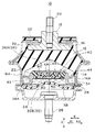
図1は、第1実施形態に係る液封入式防振装置10の縦断面図である。この防振装置10は、自動車のエンジンに取付けられる上側の第1取付け具12と、車体フレームに取付けられる下側の筒状の第2取付け具14と、これらを連結するゴム状弾性材からなる防振基体16とを備えてなるエンジンマウントである。(First embodiment)
FIG. 1 is a longitudinal sectional view of a liquid-filled
第1取付け具12は、第2取付け具14の軸芯部上方に配されたボス金具であり、径方向(即ち、軸芯方向Xに垂直な方向である軸直角方向)Kの外方Koに向けてフランジ状に突出するストッパ部18を備える。また、上端部には取付ボルト20が上向きに突設されて、このボルト20を介してエンジン側に取り付けられるよう構成されている。
The
第2取付け具14は、防振基体16が加硫成形される円筒状の筒状金具22とカップ状の底金具24とからなり、底金具24の中央部に下向きの取付ボルト26が突設され、このボルト26を介して車体側に取り付けられるように構成されている。筒状金具22は、その下端部が底金具24の上端開口部に対し、かしめ部28によりかしめ固定されている。符号30は、筒状金具22の上端部にかしめ固定されたストッパ金具であり、第1取付具12のストッパ部18との間でストッパ作用を発揮する。また、符号32は、ストッパ金具30の上面を覆うストッパゴムである。
The
防振基体16は円錐台形状に形成され、その上端部が第1取付け具12に、下端部が筒状金具22の上端開口部にそれぞれ加硫接着されている。この防振基体16の下端部に、筒状金具22の内周面を覆うゴム膜状のシール壁部34が連なっている。
The
第2取付け具14には、防振基体16の下面に対して軸芯方向Xに対向配置されて当該下面との間に液体封入室36を形成する可撓性ゴム膜からなるダイヤフラム38が取り付けられ、液体封入室36に液体が封入されている。液体封入室36は、仕切り体40により、防振基体16側の第1液室36Aとダイヤフラム38側の第2液室36Bに仕切られており、これら第1液室36Aと第2液室36Bは、絞り流路としてのオリフィス流路42を介して互いに連通されている。第1液室36Aは、防振基体16が室壁の一部をなす主液室であり、第2液室36Bは、ダイヤフラム38が室壁の一部をなす副液室である。
A
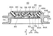
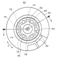
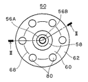
仕切り体40は、図1,2に示されるように、第2取付け具14の円筒状の周壁部14Aの内側に設けられた円環状のオリフィス形成部材44と、オリフィス形成部材44の内周面44Aに外周部46Aが加硫接着されて内周面44Aの間を塞ぐゴム弾性体からなる弾性壁46と、弾性壁46をその軸芯方向Xで挟み込む上下一対の仕切り板48,50とからなる。
As shown in FIGS. 1 and 2, the
オリフィス形成部材44は、第2取付け具14の周壁部14Aとの間に、周方向に延びるオリフィス流路42を形成する剛体からなる部材であり、該周壁部14Aの内周のシール壁部34に嵌着されている。より詳細には、オリフィス形成部材44は、第2取付け具14の周壁部14Aに同軸に配された円筒状部44Bと、該円筒状部44Bの外周側において断面コの字状に外向きに開かれた凹溝部44Cとを備えてなる。円筒状部44Bの内周面が上記内周面44Aになっている。また、凹溝部44Cにより第2取付け具14の周壁部14Aとの間で上記オリフィス流路42が形成されている。
The
オリフィス形成部材44は、ダイヤフラム38の外周縁部に埋設された補強金具38Aと、防振基体16の下端外周部に形成された受止め段部16Aとで挟持固定されている。詳細には、ダイヤフラム38の外周縁部に設けた補強金具38Aが第2取付け具14のかしめ部28でかしめ固定されており、補強金具38Aの内周縁部を覆うダイヤフラム38のゴム部分を介して、オリフィス形成部材44の下端部が補強金具38Aにより支持されている。
The
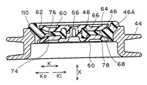
上記弾性壁46は、平面視円形状をなしており、図3に示すように、その外周部46Aが、オリフィス形成部材44の円筒状部44Bの内周面44Aに加硫接着されている。弾性壁46は、径方向中央部に軸芯方向Xに貫通する円形の連結用孔52を備え、連結用孔52の周りの表裏両側には、軸芯方向Xに突出する環状の凸条54が設けられている。
The
一対の仕切り板48,50は、図2,4に示すように連結用孔52を貫通する円柱状の連結部56を介して互いに連結されており、熱可塑性樹脂により一体に成形されている。そのうちの一方(上側)の仕切り板48が第1液室36Aの室壁の一部を構成しており、即ち、第1液室36Aに面して配されている(図1参照)。また、他方(下側)の仕切り板50が第2液室36Bの室壁の一部を構成しており、即ち、第2液室36Bに面して配されている。そして、これら一対の仕切り板48,50の軸芯方向Xにおける変位量が弾性壁46によって規制されている。
As shown in FIGS. 2 and 4, the pair of
一対の仕切り板48,50は、平面視において弾性壁46よりも外形が小さく形成されている。すなわち、仕切り板48,50の外周縁48A,50Aは、弾性壁46の外周縁が位置するオリフィス形成部材44の内周面44Aよりも径方向内方Ki側で終端している(図2参照)。
The pair of
連結部56は、図3に示すように、下側の仕切り板50に設けられた軸芯方向Xに垂直なリング状の第1平面部56Aと、第1平面部56Aから軸芯方向Xに突出する嵌合凸部56Bと、上側の仕切り板48に設けられて嵌合凸部56Bが嵌合する嵌合凹部56Cと、嵌合凹部56Cの開口縁部に設けられて軸芯方向Xに垂直なリング状の第2平面部56Dとを備えてなる。そして、図4に示すように、第1平面部56Aと第2平面部56Dが対接することで軸芯方向Xに位置決めされた状態で、嵌合凸部56Bと嵌合凹部56Cが超音波溶着により嵌合固定されている。
As shown in FIG. 3, the connecting
一対の仕切り板48,50は、中央部の連結部56の周りに、それぞれ、弾性壁46の上下の凸条54が嵌合する環状溝58が設けられている(図3,8参照)。環状溝58の外周、即ち径方向外方Ko側には、弾性壁46を軸芯方向Xで挟み込む挟持部分60が全周にわたって環状に設けられている。更に、挟持部分60の外周、即ち径方向外方Ko側に、弾性壁46の対向する壁面との間で径方向外方Ko側ほど漸次広くなるクリアランス61(図6参照)を形成するクリアランス形成部62が設けられており、該クリアランス形成部62が仕切り板48,50の外周縁部を構成している。
Each of the pair of
図6に示すように、上記挟持部分60は、その径方向中間位置を境として、それよりも径方向外方Ko側、即ち外周側を第1挟持部分64とし、径方向内方Ki側、即ち内周側を第2挟持部分66としたとき、第1挟持部分64に、第2挟持部分66よりも、弾性壁46を軸芯方向Xにおいて高い圧縮率で挟み込む高圧縮挟持部68が設けられている。すなわち、挟持部分60は、その外周側の第1挟持部分64において、弾性壁46の軸芯方向Xでの圧縮率が最も高く設定された高圧縮挟持部68を備え、この高圧縮挟持部68での圧縮率が、その径方向内方Ki側での圧縮率、及び径方向外方Ko側での圧縮率よりも高く設定されている。
As shown in FIG. 6, the sandwiching
ここで、弾性壁46の軸芯方向Xでの圧縮率とは、一対の仕切り板48,50による弾性壁46の軸芯方向Xでの圧縮量を、弾性壁46の元の厚みで割った値であり、対象となる部位での一対の仕切り板48,50の間隔をU(図4参照)とし、その部位での弾性壁46の元の厚みをT(図3参照)として、(T−U)/Tで定義される。そして、高圧縮挟持部68での圧縮率は、軸芯方向Xでの仕切り板48,50の想定される最大変位時でも、高圧縮挟持部68が弾性壁46の壁面から離れないように、即ち圧縮が残るように、高く設定されている。
Here, the compressibility in the axial direction X of the
より詳細には、この例では、図6に示すように、内周側の第2挟持部分66では、弾性壁46の軸芯方向Xでの圧縮率が略一定に設定されている。そして、外周側の第1挟持部分64において、径方向外方Ko側ほど徐々に圧縮率が高くなり、上記高圧縮挟持部68で圧縮率が最大となり、そこから径方向外方Ko側ほど徐々に圧縮率が低くなって、上記クリアランス61を形成するクリアランス形成部62に至るように設定されている。
More specifically, in this example, as shown in FIG. 6, the compression rate in the axial direction X of the
このような圧縮率の設定にするため、一対の仕切り板48,50と弾性壁46は、断面形状が、それぞれ次のように形成されている。仕切り板48,50は、第2挟持部分66から第1挟持部分64の高圧縮挟持部68に至るまで、径方向Kで間隔Uが一定となるように、軸芯方向Xに垂直な平面状に形成され、高圧縮挟持部68より外周側において、径方向外方Ko側ほど漸次軸芯方向外方Xoに位置する傾斜面状に形成されている(図4,6参照)。一方、弾性壁46は、第2挟持部分66に対向する壁面70が軸芯方向Xに垂直な平面状に形成され、その外周側部分、即ち、第1挟持部分64及び該第1挟持部分64よりも径方向外方Ko側の仕切り板部分(即ち、クリアランス形成部62)に対向する壁面72が、径方向外方Ko側ほど軸芯方向外方Xoに位置する傾斜面状に形成されている(図3,6参照)。これにより、弾性壁46は、外周部46Aが厚肉状に形成されている。仕切り板48,50の高圧縮挟持部68よりも外周側の上記傾斜面と、弾性壁46の上記壁面72の傾斜面は、ともに湾曲面状に形成されており、かつ、前者の方が勾配が大きく設定されている。これにより、上記クリアランス61は径方向外方Ko側ほど漸次広く形成されている。
In order to set the compression rate as described above, the pair of
図3に示すように、弾性壁46には、上記高圧縮挟持部68によって挟み込まれる弾性壁部分において、その壁面に軸芯方向Xに陥没する凹部74が設けられている。凹部74は、この例では、第2液室36B側に向く壁面(下側の壁面)に設けられており、図7に示すように、複数個(ここでは6個)が周方向Cに等間隔にて設けられている。これにより、高圧縮挟持部68によって挟み込まれる弾性壁部分には、薄肉状の低剛性部76が周方向Cに断続的に設けられている。
As shown in FIG. 3, the
凹部74は、この例では、径方向Kにおいて、第1挟持部分64に対向する部分の略全体にわたって設けられている。また、図7に示すように、凹部74は円弧状に形成されており、各凹部74の間には、その内周側の弾性壁部分と外周側の弾性壁部分とをなだらかに繋ぐように、径方向外方Ko側ほど漸次厚肉となる傾斜面状の高剛性部78が放射状に形成されている。そして、この高剛性部78により、高圧縮挟持部68での仕切り板50と弾性壁46との当接がなされている。
In this example, the
図2に示すように、一対の仕切り板48,50には、上記連結部56の径方向外方Ko側にて弾性壁46を挟み込む挟持部分60に、軸芯方向Xに貫通する貫通穴80がそれぞれ設けられている。貫通穴80は、図8に示すように、平面視円形状をなして、複数個(ここでは6個)が周方向Cに等間隔にて設けられている。
As shown in FIG. 2, the pair of
図7に示すように、貫通穴80は、弾性壁46の凹部74に対して軸芯方向Xに重なる位置に設けられている。すなわち、この例では、貫通穴80は、図7に示す平面視において、凹部74によって形成された低剛性部76の範囲内に入るように設けられている。複数の凹部74のそれぞれについて、軸芯方向Xに重なる位置に貫通穴80が1つずつ設けられている。また、この例では、貫通穴80は、上下の仕切り板48,50において、軸芯方向Xに重なり合うように、それぞれ設けられている。詳細には、上側の仕切り板48に設けられた複数の貫通穴80と、下側の仕切り板50に設けられた複数の貫通穴80とは、その形状、大きさ及び位置が一致させて設けられている。以上により、この例では、図5に示すように、下側の仕切り板50に設けられた貫通穴80は、凹部74に対して開口するように設けられ、上側の仕切り体48に設けられた貫通穴80は、凹部74の裏側の低剛性部76の表面に当接するように設けられている。
As shown in FIG. 7, the through
なお、符号82は、弾性壁46の外周部46Aに設けられた隆起部であり(図6参照)、弾性壁46の第1液室36A側において、その傾斜面状の上記壁面72に対して軸芯方向外方Xo側、即ち第1液室36A側に隆起して形成されている。隆起部82は、第1液室36A側の仕切り板48の上面よりも軸芯方向外方Xo側にはみ出すように突出形成されている。
また、符号84は、オリフィス形成部材44の内周面44Aに設けられた凸部であり、弾性壁46の第2液室36B側の付け根部分において、径方向内方Kiに突出形成されている。凸部84は、第2液室36B側の側面84Aが弾性壁46の軸芯方向Xに垂直な平面状に形成されて、この側面84Aが弾性壁46の成型時における成形型の押し当て面(バリ止めのためのシール面)とされている。
これらの隆起部82及び凸部84を設けたことにより、オリフィス形成部材44に対する弾性壁46の付け根部の剛性を上げて、低周波大振幅時における一対の仕切り板48,50の変位規制効果が高められている。
By providing the raised
以上よりなる本実施形態の液封入式防振装置10であると、高周波数域の微振幅振動が生じたとき、一対の仕切り板48,50が一体となって往復動することで、第1液室36Aの液圧を吸収して振動を低減することができる。そのため、高周波微振幅振動に対し、動ばね定数を効果的に低減することができる。一方、低周波数域の大振幅振動が生じたときには、一対の仕切り板48,50の変位量が弾性壁46によって規制されるので、オリフィス流路42を通って第1液室36Aと第2液室36B間で液体を流通させることができ、その液体流動効果によって振動を減衰することができる。
In the liquid-filled
しかも、本実施形態であると、高周波数域での微振幅振動の入力時に、仕切り板48,50が軸芯方向Xに微振幅振動することによって、仕切り板48,50に設けられた貫通穴80内に軸芯方向Xでの液体流動が生じ、これにより当該貫通穴80を、上記オリフィス流路42よりも高周波数域にて作用する高周波オリフィスとして用いることができる。すなわち、仕切り板48,50の移動量が弾性壁46によって規制されない微振幅入力時に、貫通穴80を高周波オリフィスとして作用させることができる。そのため、特定の周波数帯で液共振を発生させることにより、当該周波数帯の動ばね定数を低減することができる。例えば、車両性能が悪化する周波数帯に、上記貫通穴80によるオリフィスの共振を合わせ、動ばね定数を低減させることで、伝達する振動や騒音を低減することができる。なお、貫通穴80の数や開口面積、長さなどを変えることで、特性のチューニングは可能である。
Moreover, in the present embodiment, the through holes provided in the
本実施形態であると、また、弾性壁46には仕切り板48,50の挟持部分60によって挟み込まれる弾性壁部分に凹部74が設けられ、該凹部74に対して軸芯方向Xに重なる位置に貫通穴80が設けられている。このように貫通穴80に対応させて凹部74による低剛性部76が設けられているので、弾性壁46が振動しやすくなり、貫通穴80での液体流動を促進することができる。
In the present embodiment, the
本実施形態であると、また、凹部74が弾性壁46の周方向Cに複数設けられることで挟持部分60によって挟み込まれる弾性壁部分に薄肉状の低剛性部76が周方向Cに断続状に設けられ、各凹部74に対応させて貫通穴80が設けられている。これにより、貫通穴80に対応させた低剛性部76と、挟持部分60によって軸芯方向Xに圧縮された状態に挟持される高剛性部78とが、周方向Cに交互に設けられている。そのため、貫通穴80において高周波オリフィスとしての機能を持たせながら、その間の高剛性部78において弾性壁46に対する仕切り板48,50の接触状態を維持して、弾性壁46と仕切り板48,50との打音に起因する異音を低減することができる。
In the present embodiment, a plurality of the
本実施形態であると、また、一対の仕切り板48,50の挟持部分60のうち径方向外方Ko側の第1挟持部分64に、径方向内方Ki側の第2挟持部分66よりも、弾性壁46を軸芯方向Xにおいて高い圧縮率で挟み込む高圧縮挟持部68が設けられている。そのため、仕切り板48,50が弾性壁46から離れ始めるまでの仕切り板48,50の軸芯方向Xにおける変位量を大きく設定することができ、仕切り板48,50が弾性壁46から離れることに起因する異音を低減することができる。
In the present embodiment, the
この点について詳述すると、一般に中央の連結部を介して互い連結された一対の仕切り板は、軸芯方向の変位に対し、その外周縁側より弾性壁から離れていく。これに対し、本実施形態のものでは、例えば、仕切り板48,50が上方に過大変位したとき、上側の仕切り板48がその外周縁側より弾性壁46から離れようとするが、離れる起点となる外周側に高圧縮挟持部68を設けたことにより、該高圧縮挟持部68において弾性壁46に対する接触状態を維持することができ、仕切り板48,50が弾性壁46から離れ始めるまでの仕切り板48,50の軸芯方向Xにおける変位量を大きく設定することができる。特にこの例では、想定される最大の軸芯方向Xでの変位が生じたときでも、高圧縮挟持部68が弾性壁46の壁面から離れないようにこの部分の圧縮率が高く設定されているので、挟持部分60が弾性壁46から離れてしまうのを確実に防止して、異音の発生をより効果的に防止することができる。
When this point is explained in full detail, generally a pair of partition plate mutually connected via the center connection part will leave | separate from an elastic wall from the outer periphery side with respect to the displacement of an axial center direction. On the other hand, in the present embodiment, for example, when the
また、このように仕切り板48,50の挟持部分60における径方向外方Ko側に高圧縮挟持部68を設けており、径方向Kの全体で圧縮率を高くしたものではないので、弾性壁46全体の剛性アップを抑えて、高周波数振動に対する仕切り板48,50の往復動しやすさを確保することができる。また、仕切り体40の組み立て時において、軸芯方向Xに圧縮される弾性壁46のゴムの反力による連結部56での溶着不良を回避することができ、仕切り体40の組み立て性に優れる。
In addition, since the high
また、本実施形態であると、この高圧縮挟持部68によって挟み込まれる弾性壁部分に上記凹部74を設けたので、次の作用効果が奏される。すなわち、高圧縮挟持部68は、軸芯方向Xでの大変位時にも仕切り板48,50が弾性壁46から離れないようにするために軸芯方向Xでの圧縮率を高める部位である一方、軸芯方向Xでの圧縮率を高めるとその分弾性壁46は硬くなってしまう。そこで、該高圧縮挟持部68に凹部74による低剛性部76を断続状に設けたことで、径方向外方Ko側の第1挟持部分64によって挟持される弾性壁部分を硬くすることなく、むしろその部分を柔らかく維持しながら、仕切り板48,50が弾性壁46から離れないように軸芯方向Xでの圧縮率を高めることができる。また、高周波数域での微振幅振動に対し、仕切り板48,50を軸芯方向Xに往復動させやすくして、動ばね定数を低減することができる。また、該低剛性部76が外周側の第1挟持部分64に設けられたので、高周波数域の振動入力時に、一対の仕切り板48,50を、軸芯が傾くようなこじり方向での変位を抑えながら、軸芯方向Xにスムーズに往復動させることができる。
Further, in the present embodiment, since the
また、本実施形態であると、弾性壁46の外周部46Aが厚肉状に形成されたので、低周波数域の大振幅振動時に、仕切り板48,50の往復動変位を効果的に規制することができる。
In the present embodiment, since the outer
(第2実施形態)
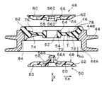
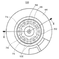
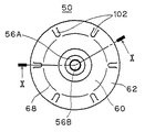
第2実施形態に係る液封入式防振装置について、図9〜13に基づいて説明する。第2実施形態は、仕切り体100の構成のみが第1実施形態とは異なる。以下、異なる点についてのみ説明する。(Second Embodiment)
A liquid-filled vibration isolator according to the second embodiment will be described with reference to FIGS. The second embodiment is different from the first embodiment only in the configuration of the
図9,10に示すように、本実施形態では、仕切り板48,50には貫通穴80は設けられていない。その代わりに、弾性壁46の第2液室36B側に向く壁面(下側の壁面)に設けられた凹部74に対し、該凹部74をその径方向外方Ko側で第2液室36Bに繋げるための径方向Kに延びる溝102が、下側の仕切り板50の板面に設けられている。これにより、上記凹部74の径方向外方Ko側において、仕切り板50の板面と弾性壁46の壁面との間には、上記溝102によって隙間104が設けられており(図11参照)、この隙間104を介して凹部74内と第2液室36Bとが液体流動可能に繋げられている。
As shown in FIGS. 9 and 10, in this embodiment, the
溝102は、凹部74に対向する仕切り板50の板面において、径方向外方Koに延びて形成されており、上記第1挟持部分64からクリアランス形成部62に至る仕切り板50の周縁部に設けられている。また、図12に示すように、溝102は、周方向Cにおいて凹部74の範囲内で設けられており、各凹部74に対応させて周方向Cに等間隔にて複数個設けられ、これにより、図13にも示されるように、各凹部74から径方向外方Ko側に延びる放射状溝に形成されている。そのため、弾性壁46は、溝102に対応した低剛性部76と、挟持部分60によって軸芯方向Xに圧縮された状態に挟持される高剛性部78とが、周方向Cに交互に設けれており、上記隙間104は、周方向Cで連続せずに所定間隔をおいて設けられている。
The
上記隙間104は、仕切り板48,50の中立位置では、凹部74と第2液室36Bとの間の液体流動を可能としつつ、大振幅振動時には一対の仕切り板48,50が軸芯方向Xに変位して溝102が弾性壁46に押し付けられることにより、閉塞されるように構成されている。ここで、中立位置とは、第1液室36Aと第2液室36Bとの間に液圧差がない状態、即ち一対の仕切り板48,50が軸芯方向Xに変位していない状態での位置である。
The
その他の構成は、仕切り体構成も含めて第1実施形態と同様であり、基本的には同様の作用効果が奏される。本実施形態特有の作用効果としては、微振幅振動時に、仕切り板50に設けた溝102によって形成された隙間104を、高周波のオリフィス流路として作用させることができるので、この部分で特定の周波数帯における液共振を発生させることができ、当該周波数帯の動ばね定数を低減することができる。また、この態様では、大振幅振動時には、仕切り板50が軸芯方向Xに変位することで上記隙間104を仕切り板50によって塞ぐことが可能となり、本来のオリフィス流路42による高減衰性能の確保に有利である。
Other configurations are the same as those of the first embodiment including the partition configuration, and basically the same functions and effects are exhibited. As a function and effect peculiar to the present embodiment, the
(第3実施形態)
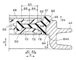
第3実施形態に係る液封入式防振装置について、図14〜17に基づいて説明する。第3実施形態は、上記第2実施形態において仕切り板50に溝102を設けたのに代えて、弾性壁46に溝110を設けたものであり、その他の構成は第2実施形態と同じである。(Third embodiment)
A liquid-filled vibration isolator according to the third embodiment will be described with reference to FIGS. In the third embodiment, instead of providing the
すなわち、本実施形態では、図14,15に示すように、仕切り板50には溝102は設けられておらず、その代わりに、弾性壁46の第2液室36B側に向く壁面(下側の壁面)に設けられた凹部74に対し、該凹部74をその径方向外方Ko側で第2液室36Bに繋げるための径方向Kに延びる溝110が、下側の仕切り板50に対向する弾性壁46の下側の壁面に設けられている。これにより、上記凹部74の径方向外方Ko側において、仕切り板50の板面と弾性壁46の壁面との間には、上記溝110によって隙間112が設けられており(図16参照)、この隙間112を介して凹部74内と第2液室36Bとが液体流動可能に繋げられている。
That is, in this embodiment, as shown in FIGS. 14 and 15, the
溝110は、凹部74からその外周側の弾性壁部分の壁面において径方向外方Koに延びて形成されている。また、図17に示すように、溝110は、周方向Cにおいて凹部74が形成された範囲内で設けられており、各凹部74に対応させて周方向Cに等間隔にて複数個設けられ、これにより、各凹部74から径方向外方Ko側に延びる放射状溝に形成されている。そのため、弾性壁46は、溝110に対応した低剛性部76と、挟持部分60によって軸芯方向Xに圧縮された状態に挟持される高剛性部78とが、周方向Cに交互に設けれており、上記隙間112は、周方向Cで連続せずに所定間隔をおいて設けられている。
The
上記隙間112は、仕切り板48,50の中立位置では、凹部74と第2液室36Bとの間の液体流動を可能としつつ、大振幅振動時には一対の仕切り板48,50が軸芯方向Xに変位して仕切り板50が溝110に押し付けられることにより、閉塞されるように構成されている。
The
本実施形態でも、第2実施形態と同様、微振幅振動時に、仕切り板50に設けた溝110によって形成された隙間112を、高周波のオリフィス流路として作用させることができるので、この部分で特定の周波数帯における液共振を発生させることができ、当該周波数帯の動ばね定数を低減することができる。また、大振幅振動時に、仕切り板50が軸芯方向Xに変位することで上記隙間112を仕切り板50によって塞ぐことが可能となり、本来のオリフィス流路42による高減衰性能の確保に有利である。その他の構成及び作用効果は第2実施形態と同様であり、説明は省略する。
In this embodiment as well, as in the second embodiment, the
(その他の実施形態)
第1実施形態において、仕切り板48,50に設けた貫通穴80の配置や数、形状は、上記実施形態に限定されるものではなく、種々の変更が可能である。第1実施形態では、上下両方の仕切り板48,50に貫通穴80を設けたが、いずれか一方のみ設けてもよい。また、第1実施形態では、弾性壁46に凹部74を設けた上でこれに重なるように貫通穴80を設けたが、凹部74に重なるように貫通穴80を設けることは必須ではなく、また凹部74を設けること自体も必須ではない。また、凹部74は、弾性壁46の下面だけでなく、上面に設けてもよく、上下両面に重なるように設けてもよい。(Other embodiments)
In 1st Embodiment, arrangement | positioning, the number, and shape of the through-
第2及び第3実施形態において、仕切り板50や弾性壁46に設けた溝102,110の配置や数、形状は、上記実施形態に限定されるものではなく、種々の変更が可能である。また、第2及び第3実施形態では、凹部74を弾性壁46の下面に設け、これに繋がる溝102,110を下側の仕切り板50や弾性壁46の下面に設けて、第2液室36Bに繋げるようにしたが、凹部を弾性壁46の上面に設けて、これに繋がる溝を上側の仕切り板48や弾性壁46の上面に設けて、第1液室36Aに繋げるように構成しても同様の作用効果が奏される。また、弾性壁46の上下両面に、これら溝及び隙間の構成を設けてもよい。また、第2実施形態における仕切り板50に溝102を設ける構成と、第3実施形態における弾性壁46に溝112を設ける構成を組み合わせて、両溝102,112によって隙間を形成するようにしてもよい。
In the second and third embodiments, the arrangement, number, and shape of the
更に、第1実施形態における仕切り板48,50に貫通穴80を設ける構成と、第2及び第3実施形態における溝102,110によって隙間104,112を設ける構成とを組み合わせることも可能である。
Furthermore, it is possible to combine the configuration in which the through
その他、一々列挙しないが、本発明の趣旨を逸脱しない限り、種々の変更が可能である。 Although not enumerated one by one, various modifications can be made without departing from the spirit of the present invention.
本発明は、自動車のエンジンマウントを始め、振動体と支持体とを防振的に結合する自動車の各種防振装置として用いることができ、また、自動車以外の各種車両に用いることもできる。 INDUSTRIAL APPLICABILITY The present invention can be used as various anti-vibration devices for automobiles, such as engine mounts for automobiles, in which vibration bodies and supports are coupled in an anti-vibration manner, and can also be used for various vehicles other than automobiles.
Claims (8)
前記仕切り体は、
前記第2取付け具の周壁部の内側に設けられて前記オリフィス流路を形成する環状のオリフィス形成部材と、
前記オリフィス形成部材の内周面の間を塞ぐゴム状弾性材からなる弾性壁と、
前記弾性壁の径方向中央部を貫通する連結部を介して互いに連結され、前記弾性壁を該弾性壁の軸芯方向で挟み込む一対の仕切り板と、からなり、前記一対の仕切り板の軸芯方向における変位量が前記弾性壁によって規制されるように構成されており、
少なくとも一方の前記仕切り板に軸芯方向に貫通する貫通穴が前記連結部の径方向外方側に設けられた
ことを特徴とする液封入式防振装置。 A first fixture, a cylindrical second fixture, a vibration-proof base made of a rubber-like elastic material connecting the first fixture and the second fixture, and the second fixture attached to the second fixture. A diaphragm made of a rubber-like elastic film that forms a liquid enclosure between the anti-vibration base and a partition that partitions the liquid enclosure into a first liquid chamber on the anti-vibration base and a second liquid chamber on the diaphragm And a liquid-filled vibration isolator comprising an orifice channel for communicating the first liquid chamber and the second liquid chamber,
The partition is
An annular orifice forming member provided inside the peripheral wall portion of the second fixture to form the orifice channel;
An elastic wall made of a rubber-like elastic material that plugs between the inner peripheral surfaces of the orifice forming member;
Wherein the radial center portion of the elastic wall via a connecting portion that penetrates are connected to each other, a pair of partition plates which sandwich the elastic wall in the axial direction of the elastic wall, made, the axis of the pair of partition plates The displacement amount in the direction is configured to be regulated by the elastic wall,
A liquid filled type vibration damping device, wherein a through hole penetrating in at least one of the partition plates in the axial direction is provided on a radially outward side of the connecting portion.
前記仕切り体は、
前記第2取付け具の周壁部の内側に設けられて前記オリフィス流路を形成する環状のオリフィス形成部材と、
前記オリフィス形成部材の内周面の間を塞ぐゴム状弾性材からなる弾性壁と、
前記弾性壁の径方向中央部を貫通する連結部を介して互いに連結され、前記弾性壁を該弾性壁の軸芯方向で挟み込む一対の仕切り板と、からなり、
少なくとも一方の前記仕切り板に軸芯方向に貫通する貫通穴が前記連結部の径方向外方側に設けられ、
前記一対の仕切り板は、前記連結部の径方向外方側に前記弾性壁を挟み込む挟持部分を有し、前記弾性壁は、前記挟持部分によって挟み込まれる弾性壁部分において前記弾性壁の表裏少なくとも一方の壁面に凹部を有し、前記凹部に対して軸芯方向に重なる位置に前記貫通穴が設けられ、
前記挟持部分が径方向外方側の第1挟持部分と径方向内方側の第2挟持部分とからなり、前記第1挟持部分に前記第2挟持部分よりも前記弾性壁を軸芯方向において高い圧縮率で挟み込む高圧縮挟持部が設けられ、前記高圧縮挟持部によって挟み込まれる弾性壁部分に前記凹部が設けられた、
ことを特徴とする液封入式防振装置。 A first fixture, a cylindrical second fixture, a vibration-proof base made of a rubber-like elastic material connecting the first fixture and the second fixture, and the second fixture attached to the second fixture. A diaphragm made of a rubber-like elastic film that forms a liquid enclosure between the anti-vibration base and a partition that partitions the liquid enclosure into a first liquid chamber on the anti-vibration base and a second liquid chamber on the diaphragm And a liquid-filled vibration isolator comprising an orifice channel for communicating the first liquid chamber and the second liquid chamber,
The partition is
An annular orifice forming member provided inside the peripheral wall portion of the second fixture to form the orifice channel;
An elastic wall made of a rubber-like elastic material that plugs between the inner peripheral surfaces of the orifice forming member;
A pair of partition plates that are connected to each other via a connecting portion that penetrates the radial center of the elastic wall, and sandwiches the elastic wall in the axial direction of the elastic wall;
A through hole penetrating at least one of the partition plates in the axial direction is provided on the radially outer side of the connecting portion;
The pair of partition plates include a sandwiching portion that sandwiches the elastic wall on a radially outer side of the connecting portion, and the elastic wall is at least one of the front and back surfaces of the elastic wall in the elastic wall portion sandwiched by the sandwiching portion. Having a recess in the wall surface, the through hole is provided at a position overlapping the recess in the axial direction,
The sandwiching portion includes a first sandwiching portion on the radially outer side and a second sandwiching portion on the radially inward side, and the elastic wall is placed in the first sandwiching portion in the axial direction than the second sandwiching portion. A high compression sandwiching part sandwiched at a high compression rate is provided, and the recess is provided in an elastic wall part sandwiched by the high compression sandwiching part.
Hydraulic antivibration device you wherein a.
前記仕切り体は、
前記第2取付け具の周壁部の内側に設けられて前記オリフィス流路を形成する環状のオリフィス形成部材と、
前記オリフィス形成部材の内周面の間を塞ぐゴム状弾性材からなる弾性壁と、
前記弾性壁の径方向中央部を貫通する連結部を介して互いに連結され、前記弾性壁を該弾性壁の軸芯方向で挟み込む一対の仕切り板と、からなり、前記一対の仕切り板の軸芯方向における変位量が前記弾性壁によって規制されるように構成されており、
前記弾性壁の表裏少なくとも一方の壁面に凹部が設けられ、前記凹部を当該凹部の径方向外方側で前記第1液室又は第2液室に繋げるための径方向に延びる溝が前記仕切り板の板面又は前記弾性壁の壁面に設けられ、前記溝によって形成される前記仕切り板の板面と前記弾性壁の壁面との隙間を介して前記凹部内と前記第1液室又は第2液室とが液体流動可能に繋げられた
ことを特徴とする液封入式防振装置。 A first fixture, a cylindrical second fixture, a vibration-proof base made of a rubber-like elastic material connecting the first fixture and the second fixture, and the second fixture attached to the second fixture. A diaphragm made of a rubber-like elastic film that forms a liquid enclosure between the anti-vibration base and a partition that partitions the liquid enclosure into a first liquid chamber on the anti-vibration base and a second liquid chamber on the diaphragm And a liquid-filled vibration isolator comprising an orifice channel for communicating the first liquid chamber and the second liquid chamber,
The partition is
An annular orifice forming member provided inside the peripheral wall portion of the second fixture to form the orifice channel;
An elastic wall made of a rubber-like elastic material that plugs between the inner peripheral surfaces of the orifice forming member;
Wherein the radial center portion of the elastic wall via a connecting portion that penetrates are connected to each other, a pair of partition plates which sandwich the elastic wall in the axial direction of the elastic wall, made, the axis of the pair of partition plates The displacement amount in the direction is configured to be regulated by the elastic wall,
A recess is provided on at least one wall surface of the elastic wall, and a radially extending groove for connecting the recess to the first liquid chamber or the second liquid chamber on the radially outer side of the recess is the partition plate. And the first liquid chamber or the second liquid through a gap between the plate surface of the partition plate formed by the groove and the wall surface of the elastic wall. A liquid-sealed vibration isolator characterized in that the chamber is connected to allow fluid flow.
前記仕切り体は、
前記第2取付け具の周壁部の内側に設けられて前記オリフィス流路を形成する環状のオリフィス形成部材と、
前記オリフィス形成部材の内周面の間を塞ぐゴム状弾性材からなる弾性壁と、
前記弾性壁の径方向中央部を貫通する連結部を介して互いに連結され、前記弾性壁を該弾性壁の軸芯方向で挟み込む一対の仕切り板と、からなり、
前記弾性壁の表裏少なくとも一方の壁面に凹部が設けられ、前記凹部を当該凹部の径方向外方側で前記第1液室又は第2液室に繋げるための径方向に延びる溝が前記仕切り板の板面又は前記弾性壁の壁面に設けられ、前記溝によって形成される前記仕切り板の板面と前記弾性壁の壁面との隙間を介して前記凹部内と前記第1液室又は第2液室とが液体流動可能に繋げられ、
前記一対の仕切り板は、前記連結部の径方向外方側に前記弾性壁を挟み込む挟持部分を有し、前記凹部が、前記挟持部分によって挟み込まれる弾性壁部分において前記弾性壁の周方向に複数設けられることで、当該弾性壁部分に薄肉状の低剛性部が周方向に断続状に設けられ、前記溝が前記各凹部から径方向外方側に延びる放射状溝に形成され、
前記挟持部分が径方向外方側の第1挟持部分と径方向内方側の第2挟持部分とからなり、前記第1挟持部分に前記第2挟持部分よりも前記弾性壁を軸芯方向において高い圧縮率で挟み込む高圧縮挟持部が設けられ、前記高圧縮挟持部によって挟み込まれる弾性壁部分に前記凹部が設けられた、
ことを特徴とする液封入式防振装置。 A first fixture, a cylindrical second fixture, a vibration-proof base made of a rubber-like elastic material connecting the first fixture and the second fixture, and the second fixture attached to the second fixture. A diaphragm made of a rubber-like elastic film that forms a liquid enclosure between the anti-vibration base and a partition that partitions the liquid enclosure into a first liquid chamber on the anti-vibration base and a second liquid chamber on the diaphragm And a liquid-filled vibration isolator comprising an orifice channel for communicating the first liquid chamber and the second liquid chamber,
The partition is
An annular orifice forming member provided inside the peripheral wall portion of the second fixture to form the orifice channel;
An elastic wall made of a rubber-like elastic material that plugs between the inner peripheral surfaces of the orifice forming member;
A pair of partition plates that are connected to each other via a connecting portion that penetrates the radial center of the elastic wall, and sandwiches the elastic wall in the axial direction of the elastic wall;
A recess is provided on at least one wall surface of the elastic wall, and a radially extending groove for connecting the recess to the first liquid chamber or the second liquid chamber on the radially outer side of the recess is the partition plate. And the first liquid chamber or the second liquid through a gap between the plate surface of the partition plate formed by the groove and the wall surface of the elastic wall. The chamber is connected to allow fluid flow,
The pair of partition plates have a sandwiching portion that sandwiches the elastic wall on the radially outer side of the connecting portion, and a plurality of the recesses are arranged in the circumferential direction of the elastic wall in the elastic wall portion sandwiched by the sandwiching portion. By being provided, the elastic wall portion is provided with a thin low-rigidity portion intermittently in the circumferential direction, and the groove is formed in a radial groove extending radially outward from each recess ,
The sandwiching portion includes a first sandwiching portion on the radially outer side and a second sandwiching portion on the radially inward side, and the elastic wall is placed in the first sandwiching portion in the axial direction than the second sandwiching portion. A high compression sandwiching part sandwiched at a high compression rate is provided, and the recess is provided in an elastic wall part sandwiched by the high compression sandwiching part.
Hydraulic antivibration device you wherein a.
Priority Applications (1)
| Application Number | Priority Date | Filing Date | Title |
|---|---|---|---|
| JP2011509199A JP5284463B2 (en) | 2009-04-13 | 2010-04-07 | Liquid-filled vibration isolator |
Applications Claiming Priority (4)
| Application Number | Priority Date | Filing Date | Title |
|---|---|---|---|
| JP2009097284 | 2009-04-13 | ||
| JP2009097284 | 2009-04-13 | ||
| JP2011509199A JP5284463B2 (en) | 2009-04-13 | 2010-04-07 | Liquid-filled vibration isolator |
| PCT/JP2010/002552 WO2010119645A1 (en) | 2009-04-13 | 2010-04-07 | Liquid-sealed vibration-isolating device |
Publications (2)
| Publication Number | Publication Date |
|---|---|
| JPWO2010119645A1 JPWO2010119645A1 (en) | 2012-10-22 |
| JP5284463B2 true JP5284463B2 (en) | 2013-09-11 |
Family
ID=42982321
Family Applications (1)
| Application Number | Title | Priority Date | Filing Date |
|---|---|---|---|
| JP2011509199A Active JP5284463B2 (en) | 2009-04-13 | 2010-04-07 | Liquid-filled vibration isolator |
Country Status (5)
| Country | Link |
|---|---|
| US (1) | US20120018936A1 (en) |
| EP (1) | EP2420699B1 (en) |
| JP (1) | JP5284463B2 (en) |
| CN (1) | CN102395809B (en) |
| WO (1) | WO2010119645A1 (en) |
Families Citing this family (4)
| Publication number | Priority date | Publication date | Assignee | Title |
|---|---|---|---|---|
| CN103890443B (en) * | 2011-12-27 | 2015-11-25 | 住友理工株式会社 | fluid-sealed vibration-damping device |
| JP6471996B2 (en) * | 2014-12-24 | 2019-02-20 | Toyo Tire株式会社 | Active vibration isolator |
| US10589615B2 (en) * | 2015-08-03 | 2020-03-17 | Ford Global Technologies, Llc | Decoupler for a hydraulic engine mount |
| JP6653206B2 (en) * | 2016-03-31 | 2020-02-26 | 山下ゴム株式会社 | Liquid ring vibration isolator |
Citations (3)
| Publication number | Priority date | Publication date | Assignee | Title |
|---|---|---|---|---|
| JP2003074617A (en) * | 2001-08-31 | 2003-03-12 | Tokai Rubber Ind Ltd | Fluid-filled anti-vibration device |
| JP2008196705A (en) * | 2008-04-01 | 2008-08-28 | Toyo Tire & Rubber Co Ltd | Fluid filled vibration isolator |
| JP2009002433A (en) * | 2007-06-21 | 2009-01-08 | Toyo Tire & Rubber Co Ltd | Liquid-filled vibration isolator |
Family Cites Families (12)
| Publication number | Priority date | Publication date | Assignee | Title |
|---|---|---|---|---|
| DE3024089C3 (en) * | 1980-06-27 | 1992-10-08 | Boge Gmbh | Hydraulically damping bearing |
| GB2237354A (en) * | 1989-10-27 | 1991-05-01 | Draftex Ind Ltd | A hydroelastic support |
| JP2884799B2 (en) * | 1991-02-04 | 1999-04-19 | 東海ゴム工業株式会社 | Fluid-filled mounting device |
| GB2297600A (en) * | 1995-02-02 | 1996-08-07 | Draftex Ind Ltd | Hydroelastic support assembly |
| GB2332498A (en) * | 1997-12-22 | 1999-06-23 | Draftex Ind Ltd | Hydroelastic supports |
| JP2006207672A (en) * | 2005-01-27 | 2006-08-10 | Toyo Tire & Rubber Co Ltd | Liquid-filled vibration isolator |
| JP2007092972A (en) * | 2005-09-30 | 2007-04-12 | Tokai Rubber Ind Ltd | Fluid filled vibration isolator |
| WO2007080705A1 (en) * | 2006-01-16 | 2007-07-19 | Toyo Tire & Rubber Co., Ltd. | Liquid-sealed vibration isolation device |
| DE102006054110A1 (en) * | 2006-11-15 | 2008-05-21 | Carl Freudenberg Kg | Hydro bearing with a wave-shaped membrane |
| JP2008164102A (en) * | 2006-12-28 | 2008-07-17 | Toyo Tire & Rubber Co Ltd | Liquid-filled vibration isolator |
| JP5264272B2 (en) * | 2008-04-30 | 2013-08-14 | 株式会社ブリヂストン | Vibration isolator |
| EP2426373B1 (en) * | 2009-04-28 | 2018-08-08 | Bridgestone Corporation | Vibration isolation device |
-
2010
- 2010-04-07 JP JP2011509199A patent/JP5284463B2/en active Active
- 2010-04-07 US US13/257,786 patent/US20120018936A1/en not_active Abandoned
- 2010-04-07 CN CN2010800164232A patent/CN102395809B/en not_active Expired - Fee Related
- 2010-04-07 WO PCT/JP2010/002552 patent/WO2010119645A1/en not_active Ceased
- 2010-04-07 EP EP10764232.4A patent/EP2420699B1/en active Active
Patent Citations (3)
| Publication number | Priority date | Publication date | Assignee | Title |
|---|---|---|---|---|
| JP2003074617A (en) * | 2001-08-31 | 2003-03-12 | Tokai Rubber Ind Ltd | Fluid-filled anti-vibration device |
| JP2009002433A (en) * | 2007-06-21 | 2009-01-08 | Toyo Tire & Rubber Co Ltd | Liquid-filled vibration isolator |
| JP2008196705A (en) * | 2008-04-01 | 2008-08-28 | Toyo Tire & Rubber Co Ltd | Fluid filled vibration isolator |
Also Published As
| Publication number | Publication date |
|---|---|
| CN102395809A (en) | 2012-03-28 |
| US20120018936A1 (en) | 2012-01-26 |
| WO2010119645A1 (en) | 2010-10-21 |
| EP2420699A4 (en) | 2017-10-25 |
| JPWO2010119645A1 (en) | 2012-10-22 |
| EP2420699A1 (en) | 2012-02-22 |
| CN102395809B (en) | 2013-11-20 |
| EP2420699B1 (en) | 2019-06-12 |
Similar Documents
| Publication | Publication Date | Title |
|---|---|---|
| CN102678811B (en) | Liquid-sealed antivibration device | |
| CN102725558B (en) | Liquid-sealed anti-vibration device | |
| JP5202729B2 (en) | Liquid-filled vibration isolator | |
| JP5919129B2 (en) | Vibration isolator | |
| JP4358891B1 (en) | Liquid-filled vibration isolator | |
| JP5284463B2 (en) | Liquid-filled vibration isolator | |
| JP4740776B2 (en) | Liquid-filled vibration isolator | |
| JP2011149493A (en) | Liquid sealed vibration control device | |
| JP5184276B2 (en) | Liquid-filled vibration isolator | |
| JP5925545B2 (en) | Liquid-filled vibration isolator | |
| JP2012202512A (en) | Fluid-filled vibration-damping device of multidirectional vibration-damping type | |
| JP2007278399A (en) | Vibration control device | |
| JP4891295B2 (en) | Liquid-filled vibration isolator | |
| JP4603014B2 (en) | Liquid-filled vibration isolator | |
| JP4158111B2 (en) | Pneumatic switching type fluid-filled engine mount | |
| JP2007218416A (en) | Liquid-filled vibration isolator | |
| JP2014031844A (en) | Vibration-proofing device | |
| JP6572104B2 (en) | Liquid-filled vibration isolator | |
| JP4555364B2 (en) | Liquid-filled vibration isolator | |
| JP5215156B2 (en) | Liquid-filled vibration isolator | |
| JP5619653B2 (en) | Liquid-filled vibration isolator | |
| JP6604825B2 (en) | Liquid-filled vibration isolator | |
| JP5690988B2 (en) | Liquid-filled vibration isolator | |
| WO2009147748A1 (en) | Liquid-sealed vibration isolator | |
| JP2010038178A (en) | Fluid-sealed vibration isolating device |
Legal Events
| Date | Code | Title | Description |
|---|---|---|---|
| A131 | Notification of reasons for refusal |
Free format text: JAPANESE INTERMEDIATE CODE: A131 Effective date: 20121009 |
|
| A521 | Request for written amendment filed |
Free format text: JAPANESE INTERMEDIATE CODE: A523 Effective date: 20121130 |
|
| TRDD | Decision of grant or rejection written | ||
| A01 | Written decision to grant a patent or to grant a registration (utility model) |
Free format text: JAPANESE INTERMEDIATE CODE: A01 Effective date: 20130521 |
|
| A61 | First payment of annual fees (during grant procedure) |
Free format text: JAPANESE INTERMEDIATE CODE: A61 Effective date: 20130529 |
|
| R150 | Certificate of patent or registration of utility model |
Ref document number: 5284463 Country of ref document: JP Free format text: JAPANESE INTERMEDIATE CODE: R150 |
|
| R250 | Receipt of annual fees |
Free format text: JAPANESE INTERMEDIATE CODE: R250 |
|
| S531 | Written request for registration of change of domicile |
Free format text: JAPANESE INTERMEDIATE CODE: R313531 |
|
| R350 | Written notification of registration of transfer |
Free format text: JAPANESE INTERMEDIATE CODE: R350 |
|
| S533 | Written request for registration of change of name |
Free format text: JAPANESE INTERMEDIATE CODE: R313533 |
|
| R350 | Written notification of registration of transfer |
Free format text: JAPANESE INTERMEDIATE CODE: R350 |
|
| R250 | Receipt of annual fees |
Free format text: JAPANESE INTERMEDIATE CODE: R250 |
|
| R250 | Receipt of annual fees |
Free format text: JAPANESE INTERMEDIATE CODE: R250 |
|
| R250 | Receipt of annual fees |
Free format text: JAPANESE INTERMEDIATE CODE: R250 |
|
| R250 | Receipt of annual fees |
Free format text: JAPANESE INTERMEDIATE CODE: R250 |
|
| R250 | Receipt of annual fees |
Free format text: JAPANESE INTERMEDIATE CODE: R250 |