JP5281126B2 - Angle detection method by resolver - Google Patents
Angle detection method by resolver Download PDFInfo
- Publication number
- JP5281126B2 JP5281126B2 JP2011156428A JP2011156428A JP5281126B2 JP 5281126 B2 JP5281126 B2 JP 5281126B2 JP 2011156428 A JP2011156428 A JP 2011156428A JP 2011156428 A JP2011156428 A JP 2011156428A JP 5281126 B2 JP5281126 B2 JP 5281126B2
- Authority
- JP
- Japan
- Prior art keywords
- signal
- time
- resolver
- detection process
- detected
- Prior art date
- Legal status (The legal status is an assumption and is not a legal conclusion. Google has not performed a legal analysis and makes no representation as to the accuracy of the status listed.)
- Expired - Fee Related
Links
- 238000001514 detection method Methods 0.000 title claims description 137
- 238000000034 method Methods 0.000 claims description 84
- 230000005284 excitation Effects 0.000 claims description 62
- 230000000694 effects Effects 0.000 description 15
- 238000005070 sampling Methods 0.000 description 13
- 230000014509 gene expression Effects 0.000 description 11
- 238000004519 manufacturing process Methods 0.000 description 8
- 230000001360 synchronised effect Effects 0.000 description 7
- 238000010586 diagram Methods 0.000 description 5
- 238000006243 chemical reaction Methods 0.000 description 4
- 230000007423 decrease Effects 0.000 description 3
- 230000000737 periodic effect Effects 0.000 description 2
- 239000007787 solid Substances 0.000 description 2
- 238000003672 processing method Methods 0.000 description 1
Images


Classifications
-
- G—PHYSICS
- G01—MEASURING; TESTING
- G01D—MEASURING NOT SPECIALLY ADAPTED FOR A SPECIFIC VARIABLE; ARRANGEMENTS FOR MEASURING TWO OR MORE VARIABLES NOT COVERED IN A SINGLE OTHER SUBCLASS; TARIFF METERING APPARATUS; MEASURING OR TESTING NOT OTHERWISE PROVIDED FOR
- G01D5/00—Mechanical means for transferring the output of a sensing member; Means for converting the output of a sensing member to another variable where the form or nature of the sensing member does not constrain the means for converting; Transducers not specially adapted for a specific variable
- G01D5/12—Mechanical means for transferring the output of a sensing member; Means for converting the output of a sensing member to another variable where the form or nature of the sensing member does not constrain the means for converting; Transducers not specially adapted for a specific variable using electric or magnetic means
- G01D5/14—Mechanical means for transferring the output of a sensing member; Means for converting the output of a sensing member to another variable where the form or nature of the sensing member does not constrain the means for converting; Transducers not specially adapted for a specific variable using electric or magnetic means influencing the magnitude of a current or voltage
- G01D5/20—Mechanical means for transferring the output of a sensing member; Means for converting the output of a sensing member to another variable where the form or nature of the sensing member does not constrain the means for converting; Transducers not specially adapted for a specific variable using electric or magnetic means influencing the magnitude of a current or voltage by varying inductance, e.g. by a movable armature
- G01D5/204—Mechanical means for transferring the output of a sensing member; Means for converting the output of a sensing member to another variable where the form or nature of the sensing member does not constrain the means for converting; Transducers not specially adapted for a specific variable using electric or magnetic means influencing the magnitude of a current or voltage by varying inductance, e.g. by a movable armature by influencing the mutual induction between two or more coils
- G01D5/2073—Mechanical means for transferring the output of a sensing member; Means for converting the output of a sensing member to another variable where the form or nature of the sensing member does not constrain the means for converting; Transducers not specially adapted for a specific variable using electric or magnetic means influencing the magnitude of a current or voltage by varying inductance, e.g. by a movable armature by influencing the mutual induction between two or more coils by movement of a single coil with respect to two or more coils
Landscapes
- Physics & Mathematics (AREA)
- General Physics & Mathematics (AREA)
- Transmission And Conversion Of Sensor Element Output (AREA)
Description
この発明は、1相励磁2相出力のレゾルバから得られる信号によって、モータなどの回転体の回転角度を検出するレゾルバによる角度検出方法に関するものである。 The present invention relates to an angle detection method by a resolver that detects a rotation angle of a rotating body such as a motor based on a signal obtained from a resolver having a single-phase excitation and two-phase output.
回転機の回転子などの回転角度を検出する方法として1相励磁2相出力のレゾルバを用いるものがある。1相励磁2相出力のレゾルバは、交流信号である励磁信号の入力を受けて、この励磁信号により励磁されるコイルを用いて回転角の余弦値、正弦値で振幅変調された2相信号(2相の正弦波変調信号)を出力する。以下では、これら各相の信号をそれぞれ第1の信号、第2の信号と呼ぶ。
1相励磁2相出力のレゾルバによる角度検出は、第1の信号及び第2の信号を符号付で検出し、この第1の信号と第2の信号を入力とする4象限逆正接(atan2)を利用し、レゾル
バ・デジタル変換(以下RD変換という。)をしている。
As a method for detecting a rotation angle of a rotor of a rotating machine, there is a method using a one-phase excitation two-phase output resolver. A resolver with one-phase excitation and two-phase output receives an excitation signal that is an alternating current signal, and uses a coil excited by this excitation signal to amplitude-modulate a two-phase signal (cosine value and sine value of the rotation angle). 2 phase sine wave modulation signal). Hereinafter, these phase signals are referred to as a first signal and a second signal, respectively.
The angle detection by the resolver of the one-phase excitation and two-phase output is performed by detecting the first signal and the second signal with a sign, and the four-quadrant arc tangent (atan2) using the first signal and the second signal as inputs. Resolver digital conversion (hereinafter referred to as RD conversion).
ここで、4象限逆正接について説明する。通常の逆正接は振幅比を用いるため、演算結果が-90〜+90度の範囲となるが、4象限逆正接は振幅比だけでなく、sin信号とcos信号の符号も勘案することで、-180〜+180度の範囲で演算結果を得ることが可能である。
例えば、第1の信号がcos信号、第2の信号がsin信号であった場合、4象限逆正接では、cos信号とsin信号のいずれもが正であれば第1象限、cos信号が負でsin信号が正であれば第2象限、cos信号が負でsin信号が負であれば第3象限、cos信号が正でsin信号が負であれば第4象限、と場合分けすることによって、-180〜+180度の範囲で回転角度が得られる。この4象限逆正接を用いたRD変換によって回転角度を得ることができる。
Here, the four quadrant arc tangent will be described. Since the normal arc tangent uses the amplitude ratio, the calculation result is in the range of -90 to +90 degrees, but the 4-quadrant arc tangent is not only the amplitude ratio but also by considering the sign of the sin signal and the cos signal, Calculation results can be obtained within the range of -180 to +180 degrees.
For example, if the first signal is a cos signal and the second signal is a sin signal, the quadrant arc tangent is negative in the first quadrant and the cos signal if both the cos signal and the sin signal are positive. By dividing the case into the second quadrant if the sin signal is positive, the third quadrant if the cos signal is negative and the sin signal is negative, and the fourth quadrant if the cos signal is positive and the sin signal is negative, The rotation angle can be obtained in the range of -180 to +180 degrees. The rotation angle can be obtained by RD conversion using the four quadrant arc tangent.
このような1相励磁2相出力のレゾルバの励磁信号は交流信号であるとともに、第1の信号と第2の信号も励磁信号と同期した交流信号である。この第1の信号と第2の信号に基づいて回転角度を検出する場合は、第1の信号と第2の信号の振幅比を利用するので、第1の信号と第2の信号の振幅精度が回転角度の検出精度を左右する。交流信号である第1の信号と第2の信号は、検出時刻によってその振幅は変化するので、従来のレゾルバによる角度検出方法では、励磁信号に同期して第1の信号と第2の信号を同時に検出するようにしていた。その理由は、例えば、第1の信号を検出してから第2の信号を検出するようにすると、第1の信号を検出した時刻に相当する第2の信号を検出することができず、その結果、第1の信号と第2の信号の振幅比の精度を保つことができずに位置検出精度も低下するためである。 The excitation signal of the resolver having such one-phase excitation and two-phase output is an AC signal, and the first signal and the second signal are also AC signals synchronized with the excitation signal. When the rotation angle is detected based on the first signal and the second signal, the amplitude ratio between the first signal and the second signal is used. Therefore, the amplitude accuracy of the first signal and the second signal is used. Affects the detection accuracy of the rotation angle. Since the amplitude of the first signal and the second signal, which are AC signals, changes depending on the detection time, the conventional angle detection method using the resolver uses the first signal and the second signal in synchronization with the excitation signal. It was trying to detect at the same time. For example, if the second signal is detected after the first signal is detected, the second signal corresponding to the time when the first signal is detected cannot be detected. As a result, the accuracy of the amplitude ratio between the first signal and the second signal cannot be maintained, and the position detection accuracy also decreases.
2相出力の第1の信号と第2の信号を同時に検出するようなレゾルバの角度検出法は、第1の信号と第2の信号の振幅比を正確に得ることで位置検出精度を保つことが可能であるが、2相出力の信号を同時に検出させる為に複数信号を同時検出できる機能を有するマイクロコンピュータや、サンプルホールド回路等のハードウェアを用いる必要があった。時間差を設けて信号を検出するようなマイクロコンピュータは、複数信号を同時検出するマイクロコンピュータより安価であるが、このようなマイクロコンピュータに、第1の信号と第2の信号を同時検出するためにサンプルホールド回路等のハードウェアを追加すると、ハードウェアの分コストアップしたり、ハードウェアの寸法分だけ回路全体の寸法が大きくなるといった問題があった。 The resolver angle detection method that simultaneously detects the first signal and the second signal of the two-phase output maintains the position detection accuracy by accurately obtaining the amplitude ratio of the first signal and the second signal. However, it is necessary to use a microcomputer having a function capable of detecting a plurality of signals at the same time, and a hardware such as a sample hold circuit in order to detect signals of two-phase outputs at the same time. A microcomputer that detects a signal with a time difference is less expensive than a microcomputer that detects a plurality of signals at the same time. In order to detect the first signal and the second signal simultaneously in such a microcomputer, When hardware such as a sample hold circuit is added, there is a problem that the cost is increased by hardware, and the size of the entire circuit is increased by the size of the hardware.
この問題を解決するため、例えば、特許文献1に記載の従来の角度検出方法では、回転角を2相の正弦波変調信号に基づいて出力するレゾルバの信号処理方法であって、レゾルバから出力される2相信号について、回転体が実質的に停止している間に規定される2相
信号の振幅ピーク発生時刻を挟んだ所定のタイミングで、2相信号の各相の信号をそれぞれサンプリングする工程と、各相の信号間のサンプリング・タイミングのずれによる誤差補正を行いつつ、サンプリングされた前記それぞれの信号に基づいて角度を演算する工程とを備えるようにしている。
このような従来の角度検出方法では、それぞれ連続して行った2度のサンプリングのタイミングが、ピークを挟んで、それぞれピークから等しい時間だけずれるようにしているので、2相出力の第1の信号と第2の信号を同時に検出することなく、第1の信号と第2の信号の振幅比を正確に検出できるようになり、その結果、複数信号を同時検出できる機能を有するマイクロコンピュータや、サンプルホールド回路等のハードウェアを用いることなく、正確な回転角度を得ることができるとされている。
In order to solve this problem, for example, the conventional angle detection method described in Patent Document 1 is a resolver signal processing method for outputting a rotation angle based on a two-phase sinusoidal modulation signal, which is output from the resolver. Step of sampling each phase signal of the two-phase signal at a predetermined timing with respect to the amplitude peak occurrence time of the two-phase signal defined while the rotating body is substantially stopped. And a step of calculating an angle based on each sampled signal while performing error correction due to a difference in sampling timing between signals of each phase.
In such a conventional angle detection method, the timing of two consecutive samplings is shifted from the peak by an equal time with the peak in between, so the first signal with two-phase output And a microcomputer having a function capable of detecting a plurality of signals simultaneously, and a sample can be accurately detected without simultaneously detecting the first signal and the second signal. It is said that an accurate rotation angle can be obtained without using hardware such as a hold circuit.
しかしながら、特許文献1に記載の従来の角度検出方法は、それぞれ連続して行った2度のサンプリングのタイミングが、ピークを挟んで、それぞれピークから等しい時間だけずれるようにしなければ、角度検出の精度が低下してしまう問題があった。
このような従来の角度検出方法では、角度検出の精度を保つために、サンプリングのタイミングを調整したり、励磁信号の位相を調整する必要があった。
また、通常、レゾルバの2相信号の振幅ピーク発生時刻は励磁信号と一定の位相差を保っているが、この位相差は製造ばらつきなどによって個々に異なったり、レゾルバの温度変化によって変化したりするため、固体毎に微調整したり、サンプリングのタイミングをオンラインで調整したりしなければ、所望の検出精度を得ることができなかった。
However, in the conventional angle detection method described in Patent Document 1, the accuracy of angle detection is not required unless the timings of two consecutive samplings are shifted from each other by an equal time with respect to the peak. There was a problem that would decrease.
In such a conventional angle detection method, it is necessary to adjust the sampling timing and the phase of the excitation signal in order to maintain the accuracy of angle detection.
Normally, the amplitude peak generation time of the two-phase signal of the resolver maintains a constant phase difference from the excitation signal, but this phase difference varies depending on manufacturing variations or changes with the temperature of the resolver. Therefore, the desired detection accuracy cannot be obtained unless fine adjustment is made for each solid or the sampling timing is adjusted online.
この発明は、上記のような問題点を解決するためになされたものであり、高価なハードウェア回路、複雑な検出シーケンスなどを必要とせず、製造ばらつきによる2相信号の振幅ピーク発生時刻の誤差やレゾルバの温度変化があっても、第1の信号と第2の信号の振幅比を正確に検出し、その結果、正確な回転角度を得ることができるレゾルバによる角度検出方法を得ることを目的としている。 The present invention has been made to solve the above-described problems, does not require an expensive hardware circuit, a complicated detection sequence, and the like, and an error in the occurrence time of an amplitude peak of a two-phase signal due to manufacturing variations. An object of the present invention is to provide a resolver angle detection method capable of accurately detecting the amplitude ratio between the first signal and the second signal even if there is a temperature change of the resolver and as a result obtaining an accurate rotation angle. It is said.
この発明に係るレゾルバによる角度検出方法は、1相励磁2相出力のレゾルバから得られる2相の正弦波変調信号である第1の信号及び第2の信号を同期検波し、前記第1の信号と前記第2の信号の振幅比に基づいて回転体の回転角度を検出する方法であって、時刻t1で前記第1の信号y1(t1)を検出し、時刻t1から第1の所定時間ΔTが経過した時刻t2で、前記第2の信号y2(t2)の順に信号を検出する第1の信号検出過程と、時刻t2から第2の所定時間後の時刻t3で前記第2の信号y2(t3)を検出し、時刻t3から前記第1の所定時間ΔTが経過した時刻t4で、前記第1の信号y1(t4)の順に信号を検出する第2の信号検出過程と、を含み、{y1(t1)−y1(t4)}と{y2(t2)−y2(t3)}の比を前記第1の信号と前記第2の信号の振幅比として検出し、該振幅比に基づいて回転体の角度を検出するようにしたものである。 Angle detection method according to a resolver according to the present invention, the first and second signals is a two-phase sine-wave modulation signal obtained from the one-phase excitation 2-phase output resolver to synchronous detection, the first A method for detecting a rotation angle of a rotating body based on an amplitude ratio between a signal and the second signal , wherein the first signal y1 (t1) is detected at a time t1, and a first predetermined time from the time t1. At time t2 when ΔT has elapsed, a first signal detection process for detecting signals in the order of the second signal y2 (t2) , and at time t3 after a second predetermined time from time t2, the second signal y2 (t3) detects, at time t4 when the first predetermined time ΔT has elapsed from time t3, see contains a second signal detection step of detecting a signal in the order of the first signal y1 (t4) , {Y1 (t1) −y1 (t4)} and {y2 (t2) −y2 (t3)} are detected as amplitude ratios of the first signal and the second signal, The angle of the rotating body is detected based on the width ratio .
この発明のレゾルバによる角度検出方法によれば、1相励磁2相出力のレゾルバから得られる第1の信号及び第2の信号の振幅比を用いて角度検出を行う方法において、第1の信号と第2の信号を同時に検出するハードウェア構成がなくても良く、また、レゾルバの温度変化や、製造ばらつきがあっても、第1の信号と第2の信号の振幅比を正確に検出し、精度良く角度を検出することが出来る等、従来にない顕著な効果を奏することができるものである。 According to the angle detection method by the resolver of the present invention, in the method of performing angle detection using the amplitude ratio of the first signal and the second signal obtained from the resolver having the one-phase excitation and two-phase output, There is no need to have a hardware configuration that simultaneously detects the second signal, and even if there is a temperature change of the resolver or manufacturing variations, the amplitude ratio between the first signal and the second signal is accurately detected, It is possible to achieve a remarkable effect that is not possible in the past, such as being able to detect the angle with high accuracy.
上述した、またその他の、この発明の目的、特徴、効果は、以下の実施の形態における詳細な説明および図面の記載からより明らかとなるであろう。 The above-described and other objects, features, and effects of the present invention will become more apparent from the detailed description and the drawings in the following embodiments.
実施の形態1.
図1は本発明の実施の形態1におけるレゾルバによる角度検出方法を説明するための構成図である。図1において、マイクロコンピュータ1は矩形波電圧出力部2を具備する。矩形波電圧出力部2が出力する矩形波電圧は、アナログローパスフィルタ3によって矩形波から正弦波状の信号に変換され、レゾルバ4に励磁信号として出力される。
矩形波電圧出力部2が出力する矩形波電圧の周波数は、本実施の形態1では10kHzとする
が、これ以外の周波数であっても良い。
レゾルバ4は1相励磁2相出力のレゾルバであり、励磁信号が入力されるとともに第1の信号(cos信号)及び第2の信号(sin信号)の2相を出力する。
レゾルバ4が出力する第1の信号及び第2の信号の周波数は、レゾルバ4に入力された励磁信号と同じ周波数である。
Embodiment 1 FIG.
FIG. 1 is a configuration diagram for explaining an angle detection method by a resolver in the first embodiment of the present invention. In FIG. 1, the microcomputer 1 includes a rectangular wave
The frequency of the rectangular wave voltage output by the rectangular wave
The
The frequency of the first signal and the second signal output from the
マイクロコンピュータ1はマルチプレクサ5を具備しており、マルチプレクサ5に前記第1の信号(cos信号)と前記第2の信号(sin信号)が入力される。
マルチプレクサ5が選択した信号はAD変換器6へ出力される。AD変換器6はマルチプレクサ5から得たアナログ信号をアナログ/デジタル変換し、デジタル信号を演算部7へ出力する。演算部7は、マルチプレクサ5が選択すべき信号をマルチプレクサ5へ出力するとともに、AD変換器6が信号を検出すべきタイミングに検出トリガ信号をAD変換器6へ出力する。
The microcomputer 1 includes a
The signal selected by the
この発明の実施の形態1における第1の信号、第2の信号を検出するタイミングを図2に示す。また、実施の形態1の動作を説明するための処理ステップのフローチャートを図3に示す。
図2は実施の形態1の動作を示す図であり、回転角度は45度となっている。
また、横軸は時刻、縦軸は各信号の振幅である。図2の上段は励磁信号、中段は第1の信号、下段は第2の信号の波形である。
本実施の形態1では、図2に示すように、「第1の所定時間(ΔT)」+「第2の所定時間
」=「励磁信号2周期(2T)」の関係を保ち、第1の信号検出過程と第2の信号検出過程をそれぞれ励磁信号に同期させている。
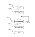
FIG. 2 shows the timing for detecting the first signal and the second signal in the first embodiment of the present invention. Further, FIG. 3 shows a flowchart of processing steps for explaining the operation of the first embodiment.
FIG. 2 is a diagram showing the operation of the first embodiment, and the rotation angle is 45 degrees.
The horizontal axis represents time, and the vertical axis represents the amplitude of each signal. The upper part of FIG. 2 is the excitation signal, the middle part is the first signal, and the lower part is the second signal.
In the first embodiment, as shown in FIG. 2, the relationship of “first predetermined time (ΔT)” + “second predetermined time” = “excitation signal two periods (2T)” is maintained, and the first The signal detection process and the second signal detection process are each synchronized with the excitation signal.
ここで、「第1の所定時間」、「第2の所定時間」について説明する。
図2において、時刻t1で第1の信号を検出し、時刻t1から第1の所定時間が経過した時刻t2で第2の信号を検出する。この励磁信号に同期し、時刻t1にて第1の信号を検出し
、第1の所定時間後となる時刻t2に第2の信号を検出する検出過程を第1の信号検出過程と定義する。
時刻t2から第2の所定時間後の時刻t3で第2の信号を検出し、時刻t3から第1の所定時間後となる時刻t4に第1の信号を検出する。この第1の信号検出過程から第2の所定時間後となる時刻t3に、第2の信号を検出し、さらに第1の所定時間後となる時刻t4に第1の信号を検出する過程を第2の信号検出過程と定義する。
Here, the “first predetermined time” and the “second predetermined time” will be described.
In FIG. 2, the first signal is detected at time t1, and the second signal is detected at time t2 when a first predetermined time has elapsed from time t1. A detection process in which the first signal is detected at time t1 in synchronization with the excitation signal and the second signal is detected at time t2 after the first predetermined time is defined as a first signal detection process.
The second signal is detected at time t3 after a second predetermined time from time t2, and the first signal is detected at time t4 after the first predetermined time from time t3. The process of detecting the second signal at a time t3 after a second predetermined time from the first signal detection process and further detecting the first signal at a time t4 after the first predetermined time. 2 signal detection process.
図2において、1段目に記載した励磁信号がレゾルバへ入力されている場合、時刻tに
おけるレゾルバが出力する第1の信号と第2の信号は、夫々以下のy1(t), y2(t)と記述できる。
In FIG. 2, when the excitation signal described in the first stage is input to the resolver, the first signal and the second signal output by the resolver at time t are respectively y1 (t) and y2 (t ).

(1)、(2)式において、Aは励磁信号の振幅に比例する定数、B,Cは検出オフセット、θはレゾルバの回転角度、f(t)は周波数10kHzの周期関数である。このf(t)の周波数は励磁信号の周波数と一致し、周期関数f(t)は、以下の(3)、(4)式の関係を満たすものである。 In the equations (1) and (2), A is a constant proportional to the amplitude of the excitation signal, B and C are detection offsets, θ is the rotation angle of the resolver, and f (t) is a periodic function with a frequency of 10 kHz. The frequency of f (t) matches the frequency of the excitation signal, and the periodic function f (t) satisfies the relationship of the following expressions (3) and (4).
(3)、(4)式において、m, nは任意の整数、Tはf(t)の周期であり、実施の形態1
におけるTは100μsecになる。(3)式は、時刻tにおけるf(t)は1/2周期前のf(t-T/2)と振幅が同じで符号が異なっていることを意味する。換言すると、T/2周期毎に反転した同一形状の波形であると言っても良い。励磁信号が正弦波状であればf(t)は周波数10kHzの
三角関数なので(3)式が成り立つが、励磁信号に歪があったとしても、時刻tにおけるf(t)は、1/2周期前のf(t-T/2)と振幅が同じで符号が異なっていれば成立する。
In the expressions (3) and (4), m and n are arbitrary integers, and T is the period of f (t).
T at 100 μsec. Equation (3) means that f (t) at time t is the same in amplitude and different in sign from f (tT / 2) 1/2 cycle before. In other words, it may be said that the waveforms have the same shape inverted every T / 2 period. If the excitation signal is sinusoidal, f (t) is a trigonometric function with a frequency of 10 kHz, so equation (3) holds. However, even if the excitation signal is distorted, f (t) at time t is 1/2 cycle. This holds if the amplitude is the same as the previous f (tT / 2) but the sign is different.
まず、第1の信号の振幅について求める。
時刻t1における第1の信号y1(t1)は(5)式、時刻t4における第1の信号y1(t4)は(6
)式となる。
First, the amplitude of the first signal is obtained.
The first signal y1 (t1) at time t1 is given by equation (5), and the first signal y1 (t4) at time t4 is given by (6
).
(5)式から(6)式を減算すると(7)式を得る。 Subtracting equation (6) from equation (5) yields equation (7).
![]()
![]()
第1の所定時間をΔT1とすると、時刻t1と時刻t4の間には(8)式の関係が成立する。
t4=t1+2T+ΔT1 ・・・・・(8)
上記(4)式と(8)式の関係から(9)式を得る。
When the first predetermined time is ΔT1, the relationship of equation (8) is established between time t1 and time t4.
t4 = t1 + 2T + ΔT1 (8)
Equation (9) is obtained from the relationship between Equation (4) and Equation (8).
この(9)式を(6)式に代入すると(10)式を得る。 Substituting this equation (9) into equation (6) yields equation (10).
![]()
![]()
同様に第2の信号の振幅について求める。時刻t2における第1の信号y2(t2)は(11)式、時刻t3における第2の信号y2(t3)は(12)式となる。 Similarly, the amplitude of the second signal is obtained. The first signal y2 (t2) at time t2 is given by equation (11), and the second signal y2 (t3) at time t3 is given by equation (12).
(11)式から(12)式を減算すると(13)式を得る。 Subtracting equation (12) from equation (11) yields equation (13).
![]()
![]()
第1の所定時間をΔT1とすると、時刻t2と時刻t3の間には(14)式の関係が成立する。
t3=t2+2T-ΔT1 ・・・・・・・・(14)
上記(4)式と(14)式の関係から(15)式を得る。
Assuming that the first predetermined time is ΔT1, the relationship of equation (14) is established between time t2 and time t3.
t3 = t2 + 2T-ΔT1 (14)
Equation (15) is obtained from the relationship between Equation (4) and Equation (14).
この(15)式を(13)式に代入すると(16)式を得る。 Substituting this equation (15) into equation (13) yields equation (16).
![]()
![]()
図2において、上述したように「第1の所定時間(ΔT)」+「第2の所定時間」=「励
磁信号2周期(2T)」の関係が成り立っているので、t1とt3の間には(17)式の関係が成立する。
t3-t1=2T ・・・・・・(17)
前記(3)式と(17)式の関係から(16)式は(18)式に置き換えてよい。
In FIG. 2, as described above, the relationship of “first predetermined time (ΔT)” + “second predetermined time” = “excitation signal two periods (2T)” is established, and therefore, between t1 and t3 Holds the relationship of equation (17).
t3-t1 = 2T (17)
From the relationship between the expressions (3) and (17), the expression (16) may be replaced with the expression (18).
![]()
![]()
前記(10)式、(18)式より(19)式を得ることができる。 Equation (19) can be obtained from Equation (10) and Equation (18).
従って、4象限逆正接atan2を利用した(20)式に従えば、レゾルバの回転角度θを
得ることができる。
Therefore, according to the equation (20) using the 4-quadrant arctangent atan2, the rotational angle θ of the resolver can be obtained.
図2に記載したように、第2の信号検出過程は、第1の信号検出過程を行ってから励磁信号のゼロクロス点を挟んで行うとともに、第1の信号検出過程は、第2の信号検出過程を行ってから第1の信号及び第2の信号のゼロクロス点を挟んで行うようにしている。
このような検出方法とすることで第1の信号検出過程と第2の信号検出過程に時間差を確保することが可能であり、励磁信号に同期して第1の信号と第2の信号を同時に検出する必要がなく、複数信号を同時検出できる機能を有するマイクロコンピュータや、サンプルホールド回路等のハードウェアを用いることなく、正確な回転角度を得ることができるといった効果を得る。
As shown in FIG. 2, the second signal detection process is performed with the zero cross point of the excitation signal sandwiched between the first signal detection process and the first signal detection process. After the process is performed, the zero cross point of the first signal and the second signal is sandwiched.
By adopting such a detection method, it is possible to secure a time difference between the first signal detection process and the second signal detection process, and the first signal and the second signal are simultaneously synchronized with the excitation signal. There is an effect that an accurate rotation angle can be obtained without using a microcomputer having a function capable of detecting a plurality of signals at the same time and a hardware such as a sample and hold circuit without the need for detection.
また、励磁信号に同期して前記第1の信号を検出し、第1の所定時間後に前記第2の信号を検出する第1の信号検出過程と、前記第1の信号検出過程から第2の所定時間後に、前記第2の信号を検出し、さらに前記第1の所定時間後に前記第1の信号を検出する第2の信号検出過程と、を含むようにしたので、時刻t1,t2,t3,t4と異なる時刻に第1の信号
若しくは第2の信号を検出しており、第1の信号と第2の信号を同時に検出していないにも関わらず、回転位置を得ることができる。
従来のレゾルバによる角度検出方法は、それぞれ連続して行った2度のサンプリングのタイミングがピークを挟んで、それぞれピークから等しい時間だけずれるようにしなければ、角度検出の精度が低下してしまう問題があった。本実施の形態1に記載のレゾルバによる角度検出方法では、(20)式を見て判るように、2度のサンプリングのタイミングがピークを挟んで、それぞれピークから等しい時間だけずれるようにしていなくても良く、レゾルバの2相信号の振幅ピーク発生時刻と励磁信号のピーク発生時刻の時間差が、製造ばらつきなどによって個々に異なったり、レゾルバの温度変化によって変化しても、固体毎に微調整したり、サンプリングのタイミングをオンラインで調整する必要がなく、所望の検出精度を得ることができるといった効果を得る。
In addition, the first signal is detected in synchronization with the excitation signal, and the second signal is detected after a first predetermined time, and the second signal is detected from the first signal detection process. A second signal detection step of detecting the second signal after a predetermined time and further detecting the first signal after the first predetermined time, so that the time t1, t2, t3 , t4 is detected at a time different from t4, and the rotation position can be obtained even though the first signal and the second signal are not detected at the same time.
The conventional angle detection method by the resolver has a problem that the accuracy of angle detection is deteriorated unless the timing of two consecutive samplings is shifted from the peak by an equal time with respect to each other. there were. In the angle detection method by the resolver described in the first embodiment, as can be seen from the equation (20), the sampling timing of 2 degrees does not deviate from the peak by an equal time with the peak in between. The time difference between the amplitude peak generation time of the two-phase signal of the resolver and the peak generation time of the excitation signal differs individually due to manufacturing variations, etc., and even if it changes due to the temperature change of the resolver, it can be finely adjusted for each solid Thus, there is no need to adjust the sampling timing online, and the desired detection accuracy can be obtained.
図3は、本実施の形態1のレゾルバによる角度検出方法の処理ステップを示すフローチャートである。このフローチャートは、ステップS001から開始する。
ステップS002で第1の信号検出過程を実行する。この第1の検出過程では、前記y1(t1), y2(t2)の値を取得する。ステップS003では第1の信号検出過程(ステップS002)の実行完了から第2の所定時間が経過したか否かを確認し、第2の所定時間が経過していなければS003でFALSE、第2の所定時間が経過していればS003でTRUEの処理を施す。
FIG. 3 is a flowchart showing processing steps of the angle detection method by the resolver according to the first embodiment. This flowchart starts from step S001.
In step S002, a first signal detection process is executed. In the first detection process, the values of y1 (t1) and y2 (t2) are acquired. In step S003, it is confirmed whether or not the second predetermined time has elapsed since the completion of the execution of the first signal detection process (step S002). If the second predetermined time has not elapsed, FALSE in S003, the second If the predetermined time has elapsed, a TRUE process is performed in S003.
ステップS004で第2の信号検出過程を実行する。この第2の検出過程では、前記y2(t3),y1(t4)の値を取得する。ステップS005では前記(20)式の演算を行い、レゾルバの回転角度θを得る。ステップS006では第2の信号検出過程(ステップS004)の実行完了から第2の所定時間が経過したか否かを確認し、第2の所定時間が経過していなければS006でFALSE、第2の所定時間が経過していればS006でTRUEの処理を施す。
図3のフローチャートに従った処理によりレゾルバの回転角度を逐次検出することができる。
In step S004, a second signal detection process is executed. In the second detection process, the values of y2 (t3) and y1 (t4) are acquired. In step S005, the calculation of the equation (20) is performed to obtain the rotational angle θ of the resolver. In step S006, it is confirmed whether or not the second predetermined time has elapsed since the completion of the execution of the second signal detection process (step S004). If the second predetermined time has not elapsed, FALSE in S006 and the second If the predetermined time has elapsed, a TRUE process is performed in S006.
The rotation angle of the resolver can be sequentially detected by the processing according to the flowchart of FIG.
図4は、前記ステップS002に記載した第1の信号検出過程について記したフローチャートであり、ステップS011から開始する。ステップS012では第1の信号を検出する。このときの時刻はt1であり、検出した第1の信号はy1(t1)として記憶しておく。
ステップS013では第1の信号を検出(ステップS012)完了から第1の所定時間ΔTが経過し
たか否かを確認し、第1の所定時間が経過していなければS013でFALSE、第1の所定時間
が経過していればS013でTRUEの処理を施す。
ステップS014では第2の信号を検出する。このときの時刻はt2であり、検出した第2の信号はy2(t2)として記憶しておく。ステップS015で第1の信号検出過程を完了する。
FIG. 4 is a flowchart describing the first signal detection process described in step S002, which starts from step S011. In step S012, the first signal is detected. The time at this time is t1, and the detected first signal is stored as y1 (t1).
In step S013, it is confirmed whether or not the first predetermined time ΔT has elapsed since the completion of the detection of the first signal (step S012). If the first predetermined time has not elapsed, FALSE is set in S013 and the first predetermined time is reached. If the time has elapsed, the process of TRUE is performed in S013.
In step S014, the second signal is detected. The time at this time is t2, and the detected second signal is stored as y2 (t2). In step S015, the first signal detection process is completed.
図5は、前記ステップS006に記載した第2の信号検出過程について記したフローチャートであり、ステップS021から開始する。ステップS022では第2の信号を検出する。このときの時刻はt3であり、検出した第2の信号はy2(t3)として記憶しておく。
ステップS023では第2の信号を検出(ステップS022)完了から第1の所定時間ΔTが経過し
たか否かを確認し、第1の所定時間が経過していなければS023でFALSE、第1の所定時間
が経過していればS023でTRUEの処理を施す。
ステップS024では第1の信号を検出する。このときの時刻はt4であり、検出した第1の信号はy1(t4)として記憶しておく。ステップS025で第2の信号検出過程を完了する。
FIG. 5 is a flowchart describing the second signal detection process described in step S006, which starts from step S021. In step S022, the second signal is detected. The time at this time is t3, and the detected second signal is stored as y2 (t3).
In step S023, it is confirmed whether or not the first predetermined time ΔT has elapsed since the completion of the detection of the second signal (step S022). If the first predetermined time has not elapsed, FALSE in S023, the first predetermined time If the time has elapsed, a TRUE process is performed in S023.
In step S024, the first signal is detected. The time at this time is t4, and the detected first signal is stored as y1 (t4). In step S025, the second signal detection process is completed.
以上のように、この発明の実施の形態1のレゾルバによる角度検出方法によれば、1相
励磁2相出力のレゾルバ4から得られる2相の正弦波変調信号である第1の信号及び第2の信号を、同期検波して角度を検出する方法であって、励磁信号に同期して第1の信号を検出し、第1の所定時間後に第2の信号を検出する第1の信号検出過程と、第1の信号検出過程から第2の所定時間後に、第2の信号を検出し、さらに第1の所定時間後に第1の信号を検出する第2の信号検出過程と、を含むようにしたので、2相出力の第1の信号と第2の信号を同時に検出することなく、第1の信号と第2の信号の振幅比を正確に検出できる。その上、図2及び(20)式から判るように、それぞれ連続して行った2度のサンプリングのタイミングがピークを挟んで、それぞれピークから等しい時間だけずれるようにしてなくても、精度良く角度検出が可能である。従って、レゾルバの2相信号の振幅ピーク発生時刻と励磁信号との位相差が、製造ばらつきなどによって個々に異なったり、レゾルバの温度変化によって変化しても、所望の検出精度を保つ効果が得られる。
As described above, according to the angle detection method using the resolver according to the first embodiment of the present invention, the first signal and the second signal, which are two-phase sinusoidal modulation signals obtained from the
また、第2の信号検出過程は、第1の信号検出過程を行ってから励磁信号のゼロクロス点を挟んで行うとともに、第1の信号検出過程は、第2の信号検出過程を行ってから励磁信号のゼロクロス点を挟んで行うことによって、第1の信号検出過程と第2の信号検出過
程に時間差を確保することが可能であり、励磁信号に同期して第1の信号と第2の信号を同時に検出する必要がなく、複数信号を同時検出できる機能を有するマイクロコンピュータや、サンプルホールド回路等のハードウェアを用いることなく、正確な回転角度を得ることができるといった効果が得られる。
In addition, the second signal detection process is performed after the first signal detection process is performed and the zero cross point of the excitation signal is sandwiched, and the first signal detection process is performed after the second signal detection process is performed. It is possible to secure a time difference between the first signal detection process and the second signal detection process by sandwiching the zero cross point of the signal, and the first signal and the second signal are synchronized with the excitation signal. Thus, there is an effect that an accurate rotation angle can be obtained without using a microcomputer having a function of simultaneously detecting a plurality of signals and hardware such as a sample hold circuit.
このように本実施の形態1のレゾルバによる角度検出方法では、同時検出するためのハードウェアが不要である。また、従来のレゾルバによる角度検出方法で必要としていた、信号のピークを挟んで、それぞれピークから等しい時間だけずれるような、サンプリングの繊細なタイミング調整や、励磁信号の位相調整は不要であり、製造ばらつきやレゾルバの温度変化に起因する検出精度低下を抑制できる、といった効果がある。 Thus, the angle detection method using the resolver according to the first embodiment does not require hardware for simultaneous detection. In addition, there is no need for fine timing adjustment of sampling and phase adjustment of excitation signal, which are necessary for the conventional angle detection method by resolver, so that they are shifted by equal time from each peak across the signal peak. There is an effect that it is possible to suppress a decrease in detection accuracy due to variations and temperature changes of the resolver.
実施の形態2.
実施の形態1では、第1の所定時間は励磁信号の半周期より大きかったが、実施の形態2では、第1の所定時間を励磁信号の半周期以内にするようにしたものである。
図6は実施の形態2の動作を示す図であり、回転角度は実施の形態1の図2と同様に45度となっている。また、横軸は時刻、縦軸は各信号の振幅である。
図6の上段は励磁信号、中段は第1の信号、下段は第2の信号の波形である。
本実施の形態2では、図6に示すように、「第1の所定時間(ΔT)」+「第2の所定時間
」=「励磁信号1.5周期(1.5T)」の関係を保ち、第1の信号検出過程と第2の信号検出過
程をそれぞれ励磁信号に同期させている。
本実施の形態2においても、時刻tにおけるレゾルバが出力する第1の信号と第2の信
号は、前記(1)、(2)、(3)、(4)式の関係が成立している。
In the first embodiment, the first predetermined time is longer than the half cycle of the excitation signal. However, in the second embodiment, the first predetermined time is set within the half cycle of the excitation signal.
FIG. 6 is a diagram showing the operation of the second embodiment, and the rotation angle is 45 degrees as in FIG. 2 of the first embodiment. The horizontal axis represents time, and the vertical axis represents the amplitude of each signal.
The upper part of FIG. 6 is the excitation signal, the middle part is the first signal, and the lower part is the second signal.
In the second embodiment, as shown in FIG. 6, the relationship of “first predetermined time (ΔT)” + “second predetermined time” = “excitation signal 1.5 period (1.5T)” is maintained. The signal detection process and the second signal detection process are synchronized with the excitation signal.
Also in the second embodiment, the relationship between the first signal and the second signal output from the resolver at time t satisfies the expressions (1), (2), (3), and (4). .
本実施の形態2における第1の信号の振幅について求める。時刻t1における第1の信号y1(t1)は、以下の(21)式、時刻t4における第1の信号y1(t4)は(22)式となる。 The amplitude of the first signal in the second embodiment is obtained. The first signal y1 (t1) at time t1 is given by the following equation (21), and the first signal y1 (t4) at time t4 is given by equation (22).
(21)式から(22)式を減算すると(23)式を得る。 Subtracting equation (22) from equation (21) yields equation (23).
![]()
![]()
第1の所定時間をΔT1とすると、時刻t1と時刻t4の間には(24)式の関係が成立する。
t4=t1+1.5T+ΔT1 ・・・・・・(24)
上記(4)式と(24)式の関係から(25)式を得る。
Assuming that the first predetermined time is ΔT1, the relationship of equation (24) is established between time t1 and time t4.
t4 = t1 + 1.5T + ΔT1 (24)
Equation (25) is obtained from the relationship between Equation (4) and Equation (24).
![]()
![]()
この(25)式を(23)式に代入すると(26)式を得る。 Substituting this equation (25) into equation (23) yields equation (26).
![]()
![]()
同様に第2の信号の振幅について求める。時刻t2における第1の信号y2(t2)は(27)式、時刻t3における第2の信号y2(t3)は(28)式となる。 Similarly, the amplitude of the second signal is obtained. The first signal y2 (t2) at time t2 is given by equation (27), and the second signal y2 (t3) at time t3 is given by equation (28).
第1の所定時間をΔT1とすると、時刻t2と時刻t3の間には(30)式の関係が成立する。
t3=t2+1.5T-ΔT1 ・・・・・・(30)
上記(4)式と(30)式の関係から(31)式を得る。
Assuming that the first predetermined time is ΔT1, the relationship of Expression (30) is established between time t2 and time t3.
t3 = t2 + 1.5T-ΔT1 (30)
Equation (31) is obtained from the relationship between Equation (4) and Equation (30).
図6において、上述したように「第1の所定時間(ΔT)」+「第2の所定時間」=「励
磁信号1.5周期(1.5T)」の関係が成り立っているので、t1とt3の間には(33)式の関係
が成立する。
t3-t1=1.5T ・・・・・・(33)
前記(4)式と(33)式の関係から(32)式は(34)式に置き換えてよい。
In FIG. 6, since the relationship of “first predetermined time (ΔT)” + “second predetermined time” = “excitation signal 1.5 period (1.5T)” is established, the interval between t1 and t3 is satisfied. (33) is established.
t3-t1 = 1.5T ・ ・ ・ ・ ・ ・ (33)
From the relationship between the equations (4) and (33), the equation (32) may be replaced with the equation (34).
従って、4象限逆正接atan2を利用した以下の(36)式に従えば、レゾルバの回転角
度θを得ることができる。
Therefore, according to the following equation (36) using the four-quadrant arctangent atan2, the rotational angle θ of the resolver can be obtained.
本実施の形態2におけるレゾルバによる角度検出方法の処理ステップを示すフローチャートは、図3、図4と同様であり、第1の所定時間及び第2の所定時間の値が異なる点と、図3のステップS005の演算が(20)式を演算する代わりに(36)式を実行する点と、が異なるのみである。 The flowchart showing the processing steps of the angle detection method by the resolver in the second embodiment is the same as that in FIG. 3 and FIG. 4, and the points of the first predetermined time and the second predetermined time are different. The only difference is that the calculation in step S005 executes equation (36) instead of calculating equation (20).
この実施の形態2では、第1の所定時間は前記励磁信号の半周期以内とした。例えば時刻t1における第1の信号y1(t1)、時刻t2における第2の信号y2(t2)は、(21)、(27)式となる。レゾルバの回転角度θが時刻によって変化する場合、厳密には時刻t1と時刻t2でレゾルバの回転角度の値が異なるが、時刻t1とt2の間隔が充分短ければ時刻t1と時刻t2とでレゾルバの回転角度は殆ど変化しないと見なすことができる。
これについては時刻t3における第2の信号y2(t3)、時刻t4における第1の信号y1(t4)についても同様である。そこで、本実施の形態2では、第1の所定時間は前記励磁信号の半周期以内とすることにより、時刻t1とt2の間隔、及び時刻t3とt4の間隔を充分短くするようにしたので、前記実施の形態1の効果に加えて、回転角度が変化する場合でも正確に回転角度が検出できるといった効果を得る。
In the second embodiment, the first predetermined time is within a half cycle of the excitation signal. For example, the first signal y1 (t1) at time t1 and the second signal y2 (t2) at time t2 are expressed by equations (21) and (27). Strictly speaking, when the resolver rotation angle θ changes with time, the value of the resolver rotation angle differs between time t1 and time t2, but if the interval between time t1 and t2 is sufficiently short, the resolver rotation time is different between time t1 and time t2. It can be considered that the rotation angle hardly changes.
The same applies to the second signal y2 (t3) at time t3 and the first signal y1 (t4) at time t4. Therefore, in the second embodiment, the first predetermined time is set within the half cycle of the excitation signal, so that the interval between the times t1 and t2 and the interval between the times t3 and t4 are sufficiently shortened. In addition to the effect of the first embodiment, the effect that the rotation angle can be accurately detected even when the rotation angle changes is obtained.
また、実施の形態1における第1の信号検出過程及び第2の信号検出過程は、第1の信号及び第2の信号のゼロクロス点付近を含んでいたが、本実施の形態2における第1の信号検出過程及び前記第2の信号検出過程は、図6に記載したように、第1の信号及び第2の信号のゼロクロス点付近を除いて行う。 In addition, the first signal detection process and the second signal detection process in the first embodiment include the vicinity of the zero cross point of the first signal and the second signal. As shown in FIG. 6, the signal detection process and the second signal detection process are performed except for the vicinity of the zero cross point of the first signal and the second signal.
例えば、第1の信号のゼロクロス点付近で第1の信号を検出した場合、検出した第1の信号はゼロ付近の値となる。同様に第2の信号のゼロクロス点付近で第2の信号を検出した場合、検出した第2の信号はゼロ付近の値となる。このような場合であっても、検出時刻が第1の信号及び第2の信号のゼロクロス点と完全に一致していなければ前記(36)式が成立し、レゾルバの2相信号の振幅ピーク発生時刻と励磁信号との位相差が、製造ばらつきなどによって個々に異なったり、レゾルバの温度変化によって変化しても、所望の検出精度を保つ効果が得られる。
しかしながら、検出した第1の信号及び第2の信号の振幅が小さいことは自明であり、信号とノイズの比(S/N比)が小さくなり、ノイズの影響を受けやすくなってしまう。
For example, when the first signal is detected near the zero cross point of the first signal, the detected first signal has a value near zero. Similarly, when the second signal is detected near the zero cross point of the second signal, the detected second signal has a value near zero. Even in such a case, if the detection time does not completely coincide with the zero cross points of the first signal and the second signal, the above equation (36) is established, and the amplitude peak of the two-phase signal of the resolver is generated. Even if the phase difference between the time and the excitation signal differs individually due to manufacturing variations or changes due to the temperature change of the resolver, an effect of maintaining a desired detection accuracy can be obtained.
However, it is obvious that the amplitudes of the detected first signal and second signal are small, and the signal-to-noise ratio (S / N ratio) becomes small, which makes it susceptible to noise.
これに対して、本実施の形態2では、第1の信号検出過程及び第2の信号検出過程は、第1の信号及び第2の信号のゼロクロス点付近を除いて行うようにしたので、S/N比を大きくしてノイズに対する誤差を抑制するといった効果を得る。
このS/N比を大きくするには、第1の信号検出過程及び第2の信号検出過程を第1の信号及び第2の信号のピーク近傍で行うようにすれば良く、これによりS/N比を高めてノイズに対する誤差を更に抑制するといった効果を得ることができる。
On the other hand, in the second embodiment, the first signal detection process and the second signal detection process are performed except for the vicinity of the zero cross point of the first signal and the second signal. The effect of suppressing the error with respect to noise by increasing the / N ratio is obtained.
In order to increase the S / N ratio, the first signal detection process and the second signal detection process may be performed in the vicinity of the peaks of the first signal and the second signal. The effect of further suppressing the error with respect to noise by increasing the ratio can be obtained.
その上、図6及び(36)式から判るように、それぞれ連続して行った2度のサンプリングのタイミングがピークを挟んで、それぞれピークから等しい時間だけずれるようにしてなくても、精度良く角度検出が可能である。従って、レゾルバの2相信号の振幅ピーク発生時刻と励磁信号との位相差が、製造ばらつきなどによって個々に異なったり、レゾルバの温度変化によって変化しても、所望の検出精度を保つ効果が得られる。 In addition, as can be seen from FIGS. 6 and (36), even if the timing of two consecutive samplings is not shifted from the peak by the same time, the angle is accurately determined. Detection is possible. Therefore, even if the phase difference between the amplitude peak generation time of the two-phase signal of the resolver and the excitation signal differs individually due to manufacturing variations or changes due to the temperature change of the resolver, an effect of maintaining a desired detection accuracy can be obtained. .
実施の形態3.
前記実施の形態2におけるレゾルバによる角度検出方法では、第1の信号検出過程は、第1の信号を検出してから該第1の信号及び第2の信号がピークに到達する前に第2の信号を検出すると共に、第2の信号検出過程は、前記第2の信号を検出してから前記第1の信号及び第2の信号がピークに到達する前に前記第1の信号を検出するようにしていた。
これに対し、本実施の形態3におけるレゾルバによる角度検出方法は、第1の信号検出過程は、第1の信号を検出してから該第1の信号及び第2の信号のピークを挟んで前記第2の信号を検出するとともに、前記第2の信号検出過程は、前記第2の信号を検出してから前記第1の信号及び第2の信号のピークを挟んで前記第1の信号を検出するようにしたものである。
In the angle detection method by the resolver in the second embodiment, the first signal detection process includes the second signal detection after the first signal is detected and before the first signal and the second signal reach the peak. In addition to detecting the signal, the second signal detecting process detects the first signal after the second signal is detected and before the first signal and the second signal reach a peak. I was doing.
On the other hand, in the angle detection method by the resolver in the third embodiment, the first signal detection process detects the first signal and then sandwiches the peak of the first signal and the second signal. In addition to detecting the second signal, the second signal detection process detects the first signal after detecting the second signal and sandwiching the peak of the first signal and the second signal. It is what you do.
図7は実施の形態3の動作を示す図であり、回転角度は実施の形態1の図2と同様に45度となっている。また、横軸は時刻、縦軸は各信号の振幅である。
図7の上段は励磁信号、中段は第1の信号、下段は第2の信号の波形である。
本実施の形態3では、図7に示すように、「第1の所定時間(ΔT)」+「第2の所定時間
」=「励磁信号0.5周期(0.5T)」の関係を保ち、第1の信号検出過程と第2の信号検出過
程をそれぞれ励磁信号に同期させている。
本実施の形態3においても、時刻tにおけるレゾルバが出力する第1の信号と第2の信
号は前記(1)、(2)、(3)、(4)式の関係が成立している。
FIG. 7 is a diagram illustrating the operation of the third embodiment, and the rotation angle is 45 degrees as in FIG. 2 of the first embodiment. The horizontal axis represents time, and the vertical axis represents the amplitude of each signal.
The upper part of FIG. 7 is the excitation signal, the middle part is the first signal, and the lower part is the second signal.
In the third embodiment, as shown in FIG. 7, the relationship of “first predetermined time (ΔT)” + “second predetermined time” = “excitation signal 0.5 period (0.5 T)” is maintained. The signal detection process and the second signal detection process are synchronized with the excitation signal.
Also in the third embodiment, the relationship of the expressions (1), (2), (3), and (4) is established between the first signal and the second signal output from the resolver at time t.
本実施の形態3における第1の信号の振幅について求める。時刻t1における第1の信号y1(t1)は、以下の(37)式、時刻t4における第1の信号y1(t4)は(38)式となる。 The amplitude of the first signal in the third embodiment is obtained. The first signal y1 (t1) at time t1 is given by the following equation (37), and the first signal y1 (t4) at time t4 is given by equation (38).
第1の所定時間をΔT1とすると、時刻t1と時刻t4の間には以下の(40)式の関係が成立する。
t4=t1+0.5T+ΔT1 ・・・・・・(40)
上記(4)式と(40)式の関係から(41)式を得る。
When the first predetermined time is ΔT1, the relationship of the following equation (40) is established between time t1 and time t4.
t4 = t1 + 0.5T + ΔT1 (40)
Equation (41) is obtained from the relationship between Equation (4) and Equation (40).
同様に第2の信号の振幅について求める。時刻t2における第1の信号y2(t2)は、以下の(43)式、時刻t3における第2の信号y2(t3)は(44)式となる。 Similarly, the amplitude of the second signal is obtained. The first signal y2 (t2) at time t2 is represented by the following equation (43), and the second signal y2 (t3) at time t3 is represented by equation (44).
第1の所定時間をΔT1とすると、時刻t2と時刻t3の間には以下の(46)式の関係が成立する。
t3=t2+0.5T-ΔT1 ・・・・・・(46)
前記(4)式と(46)式の関係から(47)式を得る。
When the first predetermined time is ΔT1, the relationship of the following equation (46) is established between time t2 and time t3.
t3 = t2 + 0.5T-ΔT1 (46)
Equation (47) is obtained from the relationship between Equation (4) and Equation (46).
図7において、上述したように「第1の所定時間(ΔT)」+「第2の所定時間」=「励
磁信号0.5周期(0.5T)」の関係が成り立っているので、t1とt3の間には(49)式の関係
が成立する。
t3-t1=0.5T ・・・・・・(49)
前記(4)式と(49)式の関係から(48)式は(50)式に置き換えてよい。
In FIG. 7, as described above, the relationship of “first predetermined time (ΔT)” + “second predetermined time” = “excitation signal 0.5 period (0.5 T)” is established. (49) is established.
t3-t1 = 0.5T ・ ・ ・ ・ ・ ・ (49)
From the relationship between the equations (4) and (49), the equation (48) may be replaced with the equation (50).
従って、4象限逆正接atan2を利用した以下の(52)式に従えば、レゾルバの回転角
度θを得ることができる。
Therefore, according to the following equation (52) using the four-quadrant arctangent atan2, the rotational angle θ of the resolver can be obtained.
前記実施の形態2に記載の(35)式と、(51)式とは同じ式である。
従って、 本実施の形態3におけるレゾルバによる角度検出方法の処理ステップを示すフローチャートは、図3、図4と同様であり、第1の所定時間及び第2の所定時間の値が異なる点以外は前記実施の形態2と同様となる。
The expression (35) and the expression (51) described in the second embodiment are the same expression.
Therefore, the flowchart showing the processing steps of the angle detection method by the resolver in the third embodiment is the same as that in FIGS. 3 and 4, except that the values of the first predetermined time and the second predetermined time are different. The same as in the second embodiment.
なお、第1の信号検出過程は、第1の信号を検出してから第1の信号及び第2の信号のピークを挟んで第2の信号を検出するとともに、第2の信号検出過程は、第2の信号を検出してから第1の信号及び第2の信号のピークを挟んで第1の信号を検出するうえで、第1の所定時間(ΔT)は、励磁信号周期Tの1/10倍以下、即ちΔT≦0.1Tにすると良い。
図8は、本実施の形態3において、第一の所定時間ΔTと励磁信号周期Tの比「ΔT÷T」と、第1の信号及び第2の信号の振幅の関係についてプロットしたものである。
SN比を勘案すれば、検出する第1の信号及び第2の信号の振幅は大きいほど良い。
振幅低下が5%以下であれば、工学的な影響は充分小さいと見なして良い。
図8の関係から「ΔT÷T≦0.1」であれば振幅低下が5%以下にすることが可能であり、
第1の所定時間(ΔT)は、励磁信号周期Tの1/10倍以下、即ちΔT≦0.1Tにすると良いこと
が判る。
The first signal detection process detects the first signal and then detects the second signal across the peak of the first signal and the second signal, and the second signal detection process includes: When the first signal is detected across the first signal and the peak of the second signal after the second signal is detected, the first predetermined time (ΔT) is 1 / of the excitation signal period T. It is preferable to make it 10 times or less, that is, ΔT ≦ 0.1T.
FIG. 8 is a plot of the relationship between the ratio “ΔT ÷ T” between the first predetermined time ΔT and the excitation signal period T and the amplitudes of the first signal and the second signal in the third embodiment. .
Considering the S / N ratio, it is better that the amplitudes of the first signal and the second signal to be detected are larger.
If the amplitude drop is 5% or less, it can be considered that the engineering influence is sufficiently small.
From the relationship of FIG. 8, if “ΔT ÷ T ≦ 0.1”, the amplitude drop can be reduced to 5% or less.
It can be seen that the first predetermined time (ΔT) should be less than 1/10 times the excitation signal period T, that is, ΔT ≦ 0.1T.
以上のように、本実施の形態3におけるレゾルバによる角度検出方法では、第1の信号検出過程は、第1の信号を検出してから第1の信号及び第2の信号のピークを挟んで第2の信号を検出するとともに、第2の信号検出過程は、第2の信号を検出してから第1の信号及び第2の信号のピークを挟んで第1の信号を検出するようにしたので、第1の信号検出過程で検出した第1の信号と第2の信号の振幅を大きく取れると同時に、第2の信号検出過程で検出した第1の信号と第2の信号の振幅も大きく取れるのでS/N比を高めてノイズに対する誤差を抑制するといった効果を得る。 As described above, in the angle detection method using the resolver according to the third embodiment, the first signal detection process detects the first signal and then sandwiches the peaks of the first signal and the second signal. Since the second signal detection process detects the second signal and then detects the first signal across the peak of the first signal and the second signal, the second signal detection process detects the second signal. The amplitudes of the first signal and the second signal detected in the first signal detection process can be increased, and at the same time, the amplitudes of the first signal and the second signal detected in the second signal detection process can be increased. Therefore, the effect of suppressing the error with respect to noise by increasing the S / N ratio is obtained.
また、本実施の形態3におけるレゾルバによる角度検出方法では、第2の所定時間は励磁信号の半周期以内とするようにしたので、第1の信号検出過程と第2の信号検出過程の時間差を短くすることができるので、回転角度が変化する場合でも第1の信号検出過程における回転位置と第2の信号検出過程における回転位置の変化を充分短くすることができる。従って、レゾルバ角度が回転している場合であっても、正確に回転角度が検出できるといった効果を得る。 Further, in the angle detection method using the resolver in the third embodiment, the second predetermined time is set to be within a half cycle of the excitation signal, so the time difference between the first signal detection process and the second signal detection process is calculated. Since it can be shortened, even when the rotation angle changes, the change in the rotation position in the first signal detection process and the rotation position in the second signal detection process can be sufficiently shortened. Therefore, even when the resolver angle is rotating, an effect that the rotation angle can be detected accurately is obtained.
その上、前記(52)式は、それぞれ連続して行った2度のサンプリングのタイミングがピークを挟んで、それぞれピークから等しい時間だけずれるようになっていなくても成立しており、この場合でも精度良く角度検出が可能である。従って、レゾルバの2相信号の振幅ピーク発生時刻と励磁信号との位相差が、製造ばらつきなどによって個々に異なったり、レゾルバの温度変化によって変化しても、所望の検出精度を保つ効果が得られる。 In addition, the above equation (52) holds even if the timing of the two consecutive samplings does not deviate from the peak by the same time with the peak in between. Angle detection is possible with high accuracy. Therefore, even if the phase difference between the amplitude peak generation time of the two-phase signal of the resolver and the excitation signal differs individually due to manufacturing variations or changes due to the temperature change of the resolver, an effect of maintaining a desired detection accuracy can be obtained. .
1 マイクロコンピュータ、2 矩形波電圧出力部、3 アナログローパスフィルタ、
4 レゾルバ、5 マルチプレクサ、6 AD変換器、7 演算部。
1 microcomputer, 2 rectangular wave voltage output unit, 3 analog low-pass filter,
4 resolver, 5 multiplexer, 6 AD converter, 7 operation unit.
Claims (7)
時刻t1で前記第1の信号y1(t1)を検出し、時刻t1から第1の所定時間ΔTが経過した時刻t2で、前記第2の信号y2(t2)の順に信号を検出する第1の信号検出過程と、
時刻t2から第2の所定時間後の時刻t3で前記第2の信号y2(t3)を検出し、時刻t3から前記第1の所定時間ΔTが経過した時刻t4で、前記第1の信号y1(t4)の順に信号を検出する第2の信号検出過程と、を含み、{y1(t1)−y1(t4)}と{y2(t2)−y2(t3)}の比を前記第1の信号と前記第2の信号の振幅比として検出し、該振幅比に基づいて回転体の角度を検出することを特徴とするレゾルバによる角度検出方法。 The first signal and the second signal is a two-phase sine-wave modulation signal obtained from the one-phase excitation 2-phase output resolver and synchronization detection, the amplitude ratio of the first signal and the second signal A method of detecting a rotation angle of a rotating body based on
Detecting said first signal y1 (t1) at time t1, at time t2 from time t1 a first predetermined time ΔT has elapsed, the first detecting signal in sequence of said second signal y2 (t2) Signal detection process;
The second signal y2 (t3) is detected at a time t3 after a second predetermined time from the time t2 , and the first signal y1 ( at the time t4 when the first predetermined time ΔT has elapsed from the time t3. It is seen containing a second signal detection process for detecting a signal in the order of t4), the, {y1 (t1) -y1 ( t4)} and {y2 (t2) -y2 (t3 )} ratio of the first of An angle detection method using a resolver, wherein the angle is detected as an amplitude ratio between a signal and the second signal, and an angle of the rotating body is detected based on the amplitude ratio .
前記第2の信号検出過程は、前記第2の信号を検出してから前記第1の信号及び第2の信号のピークを挟んで前記第1の信号を検出することを特徴とする請求項1〜請求項5のいずれか1項に記載のレゾルバによる角度検出方法。 In the first signal detection process, the first signal is detected and then the second signal is detected across the peak of the first signal and the second signal, and
The first signal is detected by sandwiching a peak of the first signal and the second signal after the second signal is detected in the second signal detection process. An angle detection method using a resolver according to claim 5.
Priority Applications (3)
| Application Number | Priority Date | Filing Date | Title |
|---|---|---|---|
| JP2011156428A JP5281126B2 (en) | 2011-07-15 | 2011-07-15 | Angle detection method by resolver |
| EP12153802.9A EP2546610B1 (en) | 2011-07-15 | 2012-02-03 | Angle detection method with resolver |
| US13/372,108 US9016123B2 (en) | 2011-07-15 | 2012-02-13 | Angle detection method with resolver |
Applications Claiming Priority (1)
| Application Number | Priority Date | Filing Date | Title |
|---|---|---|---|
| JP2011156428A JP5281126B2 (en) | 2011-07-15 | 2011-07-15 | Angle detection method by resolver |
Publications (2)
| Publication Number | Publication Date |
|---|---|
| JP2013024577A JP2013024577A (en) | 2013-02-04 |
| JP5281126B2 true JP5281126B2 (en) | 2013-09-04 |
Family
ID=45606974
Family Applications (1)
| Application Number | Title | Priority Date | Filing Date |
|---|---|---|---|
| JP2011156428A Expired - Fee Related JP5281126B2 (en) | 2011-07-15 | 2011-07-15 | Angle detection method by resolver |
Country Status (3)
| Country | Link |
|---|---|
| US (1) | US9016123B2 (en) |
| EP (1) | EP2546610B1 (en) |
| JP (1) | JP5281126B2 (en) |
Families Citing this family (8)
| Publication number | Priority date | Publication date | Assignee | Title |
|---|---|---|---|---|
| JP6527704B2 (en) * | 2015-01-29 | 2019-06-05 | ルネサスエレクトロニクス株式会社 | Semiconductor device |
| CN107276323B (en) * | 2017-08-01 | 2024-04-19 | 苏州昱泽智能科技有限公司 | Angle detection equipment, rotating body and motor system |
| JP7251751B2 (en) * | 2017-11-07 | 2023-04-04 | 株式会社松尾製作所 | Electrical angle acquisition system, electrical angle acquisition method, electrical angle acquisition program, electrical angle acquisition characteristic measurement system, electrical angle acquisition characteristic measurement method, and electrical angle acquisition characteristic measurement program |
| CN108204830B (en) * | 2017-11-28 | 2019-08-06 | 珠海格力电器股份有限公司 | Phase deviation compensation method and device |
| KR102051820B1 (en) | 2018-07-17 | 2019-12-04 | 국방과학연구소 | Apparatus for detecting rotation angle of a asynchronous resolver and Method thereof |
| JP7186846B1 (en) * | 2021-10-27 | 2022-12-09 | 三菱電機株式会社 | Control system for angle detector and AC rotating machine |
| US20240313798A1 (en) * | 2023-03-16 | 2024-09-19 | Hamilton Sundstrand Corporation | Timer-based resolver integral demodulation |
| US20240361155A1 (en) * | 2023-04-29 | 2024-10-31 | Hamilton Sundstrand Corporation | Resolver quadrant detection |
Family Cites Families (11)
| Publication number | Priority date | Publication date | Assignee | Title |
|---|---|---|---|---|
| JP3182493B2 (en) * | 1994-12-27 | 2001-07-03 | 多摩川精機株式会社 | Variable reluctance angle detector |
| US6304832B1 (en) * | 1999-03-16 | 2001-10-16 | Mitutoyo Corporation | Symmetric sampling |
| JP3574356B2 (en) * | 1999-07-19 | 2004-10-06 | オークマ株式会社 | Position detection device |
| JP2004061157A (en) | 2002-07-25 | 2004-02-26 | Toyota Motor Corp | Resolver signal processing device and signal processing method |
| JP3794690B2 (en) * | 2003-03-31 | 2006-07-05 | 川崎重工業株式会社 | Resolver digital conversion apparatus and resolver digital conversion method |
| JP4515120B2 (en) * | 2004-03-12 | 2010-07-28 | ルネサスエレクトロニクス株式会社 | Resolver digital angle conversion apparatus and method, and program |
| JP5082642B2 (en) * | 2007-07-18 | 2012-11-28 | パナソニック株式会社 | Resolver / digital conversion method and resolver / digital conversion circuit |
| JP4422757B2 (en) * | 2007-12-25 | 2010-02-24 | 日本航空電子工業株式会社 | Reference signal generation circuit, angle converter, and angle detection device |
| JP4381450B2 (en) * | 2008-01-11 | 2009-12-09 | 日本航空電子工業株式会社 | Synchronous clock generation circuit and analog / digital angle converter and angle detection device provided with synchronous clock generation circuit |
| JP4885245B2 (en) * | 2009-01-15 | 2012-02-29 | 日本航空電子工業株式会社 | RD converter and angle detection device |
| JP5173962B2 (en) * | 2009-08-06 | 2013-04-03 | 三菱電機株式会社 | Resolver / digital conversion apparatus and resolver / digital conversion method |
-
2011
- 2011-07-15 JP JP2011156428A patent/JP5281126B2/en not_active Expired - Fee Related
-
2012
- 2012-02-03 EP EP12153802.9A patent/EP2546610B1/en active Active
- 2012-02-13 US US13/372,108 patent/US9016123B2/en active Active
Also Published As
| Publication number | Publication date |
|---|---|
| US9016123B2 (en) | 2015-04-28 |
| EP2546610A3 (en) | 2017-08-30 |
| EP2546610A2 (en) | 2013-01-16 |
| JP2013024577A (en) | 2013-02-04 |
| US20130014583A1 (en) | 2013-01-17 |
| EP2546610B1 (en) | 2020-09-02 |
Similar Documents
| Publication | Publication Date | Title |
|---|---|---|
| JP5281126B2 (en) | Angle detection method by resolver | |
| JP5802588B2 (en) | Angle detection device and motor drive control device | |
| JP5173962B2 (en) | Resolver / digital conversion apparatus and resolver / digital conversion method | |
| JP6005781B2 (en) | Resolver device | |
| US10989568B2 (en) | Position detection device and position detection method | |
| US9068861B2 (en) | Resolver interface | |
| CN111464107B (en) | Motor, motor data analysis method, device and system | |
| KR101338707B1 (en) | Excitation signal generating device and resolver sensing device | |
| KR101834526B1 (en) | Apparatus for compensating output signal of magnetic encoder | |
| JP2014157069A (en) | Position detector | |
| JP5733250B2 (en) | Position detection device | |
| JP5895680B2 (en) | Signal processing device | |
| JP2014238331A (en) | Angle detection device and angle detection method | |
| JP5821764B2 (en) | Position detection device | |
| JP6583738B2 (en) | Phase measuring device and equipment to which the phase measuring device is applied | |
| JP2013224865A (en) | Signal processing device | |
| JP2013024766A (en) | Motor speed detecting device and motor control device | |
| CN102692540A (en) | Frequency tracking alternating-current sampling method | |
| CN110869710A (en) | Measuring method using inductive displacement sensor | |
| JP5361658B2 (en) | Resolver digital converter | |
| CN107421435A (en) | Homodyne orthogonal laser interference signal generation method based on digit shifter | |
| JP2008196888A (en) | Phase difference detection device and rotational position detection device | |
| JP2016020819A (en) | Angle detection device and motor drive circuit | |
| JP6430274B2 (en) | Phase difference detection method | |
| JP2013083500A (en) | Angle detector |
Legal Events
| Date | Code | Title | Description |
|---|---|---|---|
| A131 | Notification of reasons for refusal |
Free format text: JAPANESE INTERMEDIATE CODE: A131 Effective date: 20121211 |
|
| A521 | Request for written amendment filed |
Free format text: JAPANESE INTERMEDIATE CODE: A523 Effective date: 20130124 |
|
| TRDD | Decision of grant or rejection written | ||
| A01 | Written decision to grant a patent or to grant a registration (utility model) |
Free format text: JAPANESE INTERMEDIATE CODE: A01 Effective date: 20130507 |
|
| A61 | First payment of annual fees (during grant procedure) |
Free format text: JAPANESE INTERMEDIATE CODE: A61 Effective date: 20130523 |
|
| R151 | Written notification of patent or utility model registration |
Ref document number: 5281126 Country of ref document: JP Free format text: JAPANESE INTERMEDIATE CODE: R151 |
|
| R250 | Receipt of annual fees |
Free format text: JAPANESE INTERMEDIATE CODE: R250 |
|
| R250 | Receipt of annual fees |
Free format text: JAPANESE INTERMEDIATE CODE: R250 |
|
| R250 | Receipt of annual fees |
Free format text: JAPANESE INTERMEDIATE CODE: R250 |
|
| R250 | Receipt of annual fees |
Free format text: JAPANESE INTERMEDIATE CODE: R250 |
|
| R250 | Receipt of annual fees |
Free format text: JAPANESE INTERMEDIATE CODE: R250 |
|
| R250 | Receipt of annual fees |
Free format text: JAPANESE INTERMEDIATE CODE: R250 |
|
| R250 | Receipt of annual fees |
Free format text: JAPANESE INTERMEDIATE CODE: R250 |
|
| LAPS | Cancellation because of no payment of annual fees |