KR102051820B1 - Apparatus for detecting rotation angle of a asynchronous resolver and Method thereof - Google Patents
Apparatus for detecting rotation angle of a asynchronous resolver and Method thereof Download PDFInfo
- Publication number
- KR102051820B1 KR102051820B1 KR1020180082854A KR20180082854A KR102051820B1 KR 102051820 B1 KR102051820 B1 KR 102051820B1 KR 1020180082854 A KR1020180082854 A KR 1020180082854A KR 20180082854 A KR20180082854 A KR 20180082854A KR 102051820 B1 KR102051820 B1 KR 102051820B1
- Authority
- KR
- South Korea
- Prior art keywords
- resolver
- cosine
- time delay
- cos
- sin
- Prior art date
Links
Images
Classifications
-
- G—PHYSICS
- G01—MEASURING; TESTING
- G01D—MEASURING NOT SPECIALLY ADAPTED FOR A SPECIFIC VARIABLE; ARRANGEMENTS FOR MEASURING TWO OR MORE VARIABLES NOT COVERED IN A SINGLE OTHER SUBCLASS; TARIFF METERING APPARATUS; MEASURING OR TESTING NOT OTHERWISE PROVIDED FOR
- G01D5/00—Mechanical means for transferring the output of a sensing member; Means for converting the output of a sensing member to another variable where the form or nature of the sensing member does not constrain the means for converting; Transducers not specially adapted for a specific variable
- G01D5/12—Mechanical means for transferring the output of a sensing member; Means for converting the output of a sensing member to another variable where the form or nature of the sensing member does not constrain the means for converting; Transducers not specially adapted for a specific variable using electric or magnetic means
- G01D5/14—Mechanical means for transferring the output of a sensing member; Means for converting the output of a sensing member to another variable where the form or nature of the sensing member does not constrain the means for converting; Transducers not specially adapted for a specific variable using electric or magnetic means influencing the magnitude of a current or voltage
- G01D5/20—Mechanical means for transferring the output of a sensing member; Means for converting the output of a sensing member to another variable where the form or nature of the sensing member does not constrain the means for converting; Transducers not specially adapted for a specific variable using electric or magnetic means influencing the magnitude of a current or voltage by varying inductance, e.g. by a movable armature
-
- G—PHYSICS
- G01—MEASURING; TESTING
- G01D—MEASURING NOT SPECIALLY ADAPTED FOR A SPECIFIC VARIABLE; ARRANGEMENTS FOR MEASURING TWO OR MORE VARIABLES NOT COVERED IN A SINGLE OTHER SUBCLASS; TARIFF METERING APPARATUS; MEASURING OR TESTING NOT OTHERWISE PROVIDED FOR
- G01D5/00—Mechanical means for transferring the output of a sensing member; Means for converting the output of a sensing member to another variable where the form or nature of the sensing member does not constrain the means for converting; Transducers not specially adapted for a specific variable
- G01D5/12—Mechanical means for transferring the output of a sensing member; Means for converting the output of a sensing member to another variable where the form or nature of the sensing member does not constrain the means for converting; Transducers not specially adapted for a specific variable using electric or magnetic means
- G01D5/244—Mechanical means for transferring the output of a sensing member; Means for converting the output of a sensing member to another variable where the form or nature of the sensing member does not constrain the means for converting; Transducers not specially adapted for a specific variable using electric or magnetic means influencing characteristics of pulses or pulse trains; generating pulses or pulse trains
Landscapes
- Physics & Mathematics (AREA)
- General Physics & Mathematics (AREA)
- Transmission And Conversion Of Sensor Element Output (AREA)
Abstract
Description
본 발명은 회전각 검출 기술에 관한 것으로서, 더 상세하게는 리졸버를 이용한 회전각 검출에 있어 리졸버 회전자에서 전달받은 참조용 정현파 신호의 시간 지연에 대한 추정 회로를 없앤 비동기 방식의 효율적인 리졸버 디지털 변환을 구현하는 비동기 리졸버 회전각 검출기 및 이의 방법에 대한 것이다.The present invention relates to a rotation angle detection technique, and more particularly, to asynchronous resolver digital conversion that eliminates an estimation circuit for the time delay of a reference sinusoidal signal transmitted from a resolver rotor in rotation angle detection using a resolver. An asynchronous resolver rotation angle detector and its method are implemented.
리졸버는 김발, 모터(전동기)의 회전자 위치와 속도의 정밀 측정에 있어 널리 유용하게 사용하는 장치이다. 그리고, 회전자의 위치와 속도를 측정하는 데에는 포텐셜 미터, 타코 미터 등이 있지만, 실외 환경에 온도 변화가 심한 환경에서 회로의 강인성 확보와 높은 정밀도를 얻기에는 한계가 있다. The resolver is a widely used device for precise measurement of rotor position and speed of gimbal and motor (motor). In addition, there are potential meters and tachometers for measuring the position and speed of the rotor, but there are limitations in securing the robustness of the circuit and obtaining high precision in an environment where temperature changes are severe in the outdoor environment.
여기에서, 리졸버는 수 KHz의 주파수를 갖는 참조용 정현파 신호를 회전자(rotor) 단에 입력하면 이 회전자의 위치에 상응하는 크기를 갖는 자기 유도된 파형이 각각 cos, sin 성분의 고정자(stator) 단을 통해 출력된다. Here, when the resolver inputs a reference sinusoidal signal having a frequency of several KHz to the rotor stage, a magnetically induced waveform having a magnitude corresponding to the position of the rotor is a stator of cos and sin components, respectively. ) Is output through
이 리졸버 회전각 검출기는 리졸버의 회전자의 위치에 따라 cos, sin 성분의 고정자 단의 서로 상대적인 출력 값의 차이를 이용하여 회전자의 위치를 탐지하는 장치이다.The resolver rotation angle detector is a device that detects the position of the rotor by using the difference in output values of the stator stages of the cos and sin components according to the position of the rotor of the resolver.
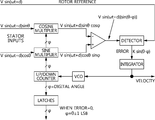
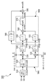
회전각 검출기에 대한 종래 기술이 이미 개시되어 있다. 우선, 첫 번째 종래 기술이 도 1에 도시된다. 도 1을 참조하면, 회전자 위치, θ를 얻기 위해 재귀 회로를 구성하여 연속된 추적 루프 회로를 구성하는 방식이다. The prior art for rotation angle detectors is already disclosed. First, the first prior art is shown in FIG. Referring to FIG. 1, a continuous tracking loop circuit is configured by configuring a recursive circuit to obtain a rotor position θ.
이를 위해 리졸버의 회전각을 구하기 위해 각종 해당된 디지털 로직 회로(카운터, 래치 등)와 VCO(Voltage Controlled Oscillator)와 같은 아날로그 부품(회로)이 요구된다. 여기에서, 회전각 검출기에 나온 시간 지연, d는 회전자에 정현파 신호를 인가하는 기준 시점에서 회전각 검출기 복조 회로에 도달하는 시간을 의미한다. 여기서, LSB는 Least Significant Bit를 나타낸다.To this end, various corresponding digital logic circuits (counters, latches, etc.) and analog components (circuit controlled oscillators) are required to determine the rotation angle of the resolver. Here, the time delay, d, which has appeared in the rotation angle detector, means the time to reach the rotation angle detector demodulation circuit at the reference time of applying a sinusoidal signal to the rotor. Here, LSB stands for Least Significant Bit.
위 도 1에 도시된 바와 같이, 이 시간 지연 값의 정확한 추정 작업은 정확한 리졸버의 회전각, θ값을 위해서는 반드시 필요로 하고 있다. 만약에 여러 조건으로 인해 sin 고정자 단의 입력 신호, V sin(wt+d) sin(θ)의 시간 지연, d 값이 cos 고정자 단의 입력 신호, Vsin(wt+d) sin(θ)의 시간 지연, d 값과 서로 같지 않다면, 이와 같은 기술을 사용한 회전각 검출기는 올바른 회전각 값을 얻을 수 없다는 단점이 있다.As shown in FIG. 1 above, accurate estimation of the time delay value is necessary for accurate rotation angle of the resolver and θ value. If the input signal of the sin stator stage, the time delay of V sin (wt + d) sin (θ), d is the input signal of the cos stator stage, Vsin (wt + d) sin (θ) If the delay, d value is not equal to each other, the rotation angle detector using this technique has the disadvantage that it cannot obtain the correct rotation angle value.
또한, 리졸버의 회전각을 계산하기 이전에 항상 시간 지연을 추정하는 회로는 우선적으로 동작되어야 한다는 단점이 있다.In addition, there is a disadvantage that a circuit which always estimates the time delay before calculating the rotation angle of the resolver should be operated first.
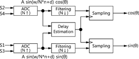
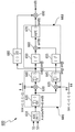
다른 방식의 종래 기술이 도 2에 도시된다. 도 2를 참조하면, ADC(Analog Digital Converter)(N 업-샘플링), 필터링(Filtering), N 다운-샘플링(down-sampling) 형태로 구성되어 있다. 이 방식의 기법도 각각의 고정자 별로 회전자의 회전각을 정확하게 구하기 위해 “지연 평가(delay estimation)”블록을 필요로 한다. Another way of prior art is shown in FIG. 2. Referring to FIG. 2, an analog digital converter (ADC) (N up-sampling), filtering, and N down-sampling are configured. This technique also requires a "delay estimation" block to accurately determine the rotation angle of the rotor for each stator.
이 블록의 기능은 sin(w/N*n+d) 정현파에서 시간 지연, d를 획득하는 것이다. 그런데, 만약에 θ 성분이 90*x 도(여기에서, x는 정수 값)에 위치할 경우는 어느 한쪽의 고정자 단의 입력 크기가 0이 된다. 그런데, 만약에 0의 크기를 갖는 고정자 단을 사용할 경우는 시간 지연을 정확하게 추정할 수 없다는 단점이 있다.The function of this block is to obtain a time delay, d, from the sin (w / N * n + d) sinusoid. However, if the θ component is located at 90 * x degrees (where x is an integer value), the input size of either stator stage is zero. However, if a stator stage having a magnitude of zero is used, a time delay cannot be accurately estimated.
또한, 각 고정자 단에 따라 실질적인 시간 지연 값이 다른 경우에서는 정확한 회전각 검출에 있어 오차 값의 증가와 추가 보상을 위한 데이터 처리를 필요로 한다는 단점이 있다.In addition, in the case where the actual time delay value is different for each stator stage, there is a disadvantage in that the accurate rotation angle detection requires data processing for an increase of an error value and additional compensation.
본 발명은 위 배경기술에 따른 문제점을 해소하기 위해 제안된 것으로서, 리졸버 회전자에서 전달받은 참조용 정현파 신호의 시간 지연에 대한 추정 회로를 없앤 비동기 방식의 효율적인 리졸버 디지털 변환을 구현하는 비동기 리졸버 회전각 검출기 및 이의 방법을 제공하는데 그 목적이 있다.SUMMARY OF THE INVENTION The present invention has been proposed to solve the problems according to the above background technology, and an asynchronous resolver rotation angle that implements an efficient resolver digital conversion of an asynchronous method by eliminating an estimation circuit for a time delay of a reference sinusoidal signal transmitted from a resolver rotor. It is an object of the present invention to provide a detector and a method thereof.
또한, 본 발명은 0의 크기를 갖는 고정자 단을 사용할 경우는 시간 지연을 정확하게 추정할 수 있는 비동기 리졸버 회전각 검출기 및 이의 방법을 제공하는데 다른 목적이 있다.Another object of the present invention is to provide an asynchronous resolver rotation angle detector and a method thereof capable of accurately estimating a time delay when using a stator stage having a magnitude of zero.
또한, 본 발명은 오차 값의 증가와 추가 보상을 위한 데이터 처리를 필요로 하지 않으면서도 각 고정자 단에 따라 실질적인 시간 지연 값이 다른 경우에서도 정확한 회전각을 검출할 수 있는 비동기 리졸버 회전각 검출기 및 이의 방법을 제공하는데 또 다른 목적이 있다.In addition, the present invention provides an asynchronous resolver rotation angle detector capable of detecting an accurate rotation angle even when the actual time delay value is different for each stator stage without increasing the error value and additional data processing for compensation. Another purpose is to provide a method.
본 발명은 위에서 제시된 과제를 달성하기 위해, 리졸버 회전자에서 전달받은 참조용 정현파 신호의 시간 지연에 대한 추정 회로를 없앤 비동기 방식의 효율적인 리졸버 디지털 변환을 구현하는 비동기 리졸버 회전각 검출기를 제공한다.The present invention provides an asynchronous resolver rotation angle detector that implements an efficient resolver digital conversion in an asynchronous manner by eliminating the estimation circuit for the time delay of a reference sinusoidal signal transmitted from a resolver rotor.
상기 비동기 리졸버 회전각 검출기는,The asynchronous resolver rotation angle detector,
리졸버;Resolver;
상기 리졸버로부터 리졸버 코사인 고정자 단에 해당되는 제 1 입력 신호를 입력받아 상기 제 1 입력 신호로부터 전체 시간 지연값을 제거하여 최종 코사인 성분만을 출력하는 리졸버 디지털 변환기 코사인 모듈; 및A resolver digital converter cosine module which receives a first input signal corresponding to a resolver cosine stator stage from the resolver and removes a total time delay value from the first input signal to output only a final cosine component; And
상기 리졸버로부터 리졸버 사인 고정자 단에 해당되는 제 2 입력 신호를 입력받아 상기 제 2 입력 신호로부터 전체 시간 지연값을 제거하여 최종 사인 성분만을 출력하는 리졸버 디지털 변환기 사인 모듈;을 포함하는 것을 특징으로 한다.And a resolver digital converter sine module that receives a second input signal corresponding to a resolver sine stator stage from the resolver, removes a total time delay value from the second input signal, and outputs only a final sine component.
이때, 상기 리졸버 디지털 변환기 코사인 모듈은, 상기 제 1 입력 신호를 제 1 디지털 신호로 변환하는 제 1 ADC(Analog-Digital Converter); 상기 제 1 디지털 신호로부터 전체 시간 지연값을 산출하는 제 1 전체 시간 지연 산출부; 및 상기 전체 시간 지연값을 제거하고 제 1 절대치의 코사인 성분만을 산출하는 코사인 산출부;를 포함하는 것을 특징으로 한다.In this case, the resolver digital converter cosine module may include a first ADC (Analog-Digital Converter) for converting the first input signal into a first digital signal; A first total time delay calculator for calculating a total time delay value from the first digital signal; And a cosine calculator for removing the total time delay value and calculating only the cosine component of the first absolute value.
또한, 상기 제 1 전체 시간 지연 산출부는, 상기 제 1 디지털 신호를 미리 설정된 주기로 누적하여 누적 신호를 생성하는 제 1 최초 누적 회로; 상기 누적 신호에 미리 설정되는 설정 사인 성분 및 설정 코사인 성분을 곱하기 연산을 통하여 제 1 중간 출력 신호를 각각 생성하는 제 1-1 및 제 1-2 곱셈기; 및 삼각함수 특성을 이용하여 상기 제 1 중간 출력 신호로부터 전체 시간 지연값을 갖는 코사인 및 모터의 회전각을 갖는 코사인의 제 1-1 곱 및 전체 시간 지연값을 갖는 사인 및 모터의 회전각을 갖는 코사인의 제 1-2 곱을 각각 산출하는 제 1-1 및 제 1-2 중간 누적 회로;를 포함하는 것을 특징으로 한다.The first total time delay calculating unit may further include: a first initial accumulation circuit accumulating the first digital signal at a predetermined period to generate a cumulative signal; 1-1 and 1-2 multipliers for generating a first intermediate output signal by multiplying the accumulated signal by a preset sine component and a preset cosine component; And a rotation angle of a sine having a total time delay value and a sine having a first time product of a cosine having a total time delay value and a cosine having a rotation angle of the motor and a total time delay value from the first intermediate output signal using a trigonometric characteristic. And 1-1 and 1-2 intermediate cumulative circuits for calculating the 1-2 products of the cosine, respectively.
또한, 상기 코사인 산출부는, 상기 제 1-1 곱 및 제 1-2 곱을 각각 제곱하는 제 1-1 및 1-2 제곱 회로; 삼각함수 특성을 이용하여 회전각을 갖는 코사인의 제 1 제곱값을 산출하는 제 1 합산기; 및 상기 제 1 제곱값을 제곱근 공식을 이용하여 제 1 절대치로 변환하는 제 1 제곱근 회로;를 포함하는 것을 특징으로 한다.The cosine calculating unit may include first and second square circuits that square the first and second products, respectively; A first summer for calculating a first square value of the cosine having the rotation angle by using a trigonometric function; And a first square root circuit for converting the first square value to a first absolute value using a square root formula.
또한, 상기 리졸버 디지털 변환기 코사인 모듈은, 상기 제 1-1 곱을 미리 설정되는 기준값과 비교하여 양 또는 음의 부호를 산출하는 제 1 비교기; 및 상기 양 또는 음의 부호를 상기 제 1 절대치에 곱 연산을 수행하여 상기 최종 코사인 성분만을 출력하는 제 1 최종 곱셈기;를 포함하는 것을 특징으로 한다.The resolver digital converter cosine module may further include a first comparator configured to calculate a positive or negative sign by comparing the first-1 product with a preset reference value; And a first final multiplier configured to multiply the positive or negative sign by the first absolute value to output only the final cosine component.
또한, 상기 리졸버 디지털 변환기 사인 모듈은, 상기 제 2 입력 신호를 제 2 디지털 신호로 변환하는 제 2 ADC(Analog-Digital Converter); 전체 시간 지연값을 산출하는 제 2 전체 시간 지연 산출부; 및 상기 전체 시간 지연값을 제거하고 제 2 절대치의 사인 성분만을 산출하는 사인 산출부;를 포함하는 것을 특징으로 한다.The resolver digital converter sign module may further include a second analog-to-digital converter (ADC) for converting the second input signal into a second digital signal; A second total time delay calculator for calculating a total time delay value; And a sine calculator for removing the total time delay value and calculating only a sine component of a second absolute value.
또한, 상기 제 2 전체 시간 지연 산출부는, 상기 제 2 디지털 신호를 미리 설정된 주기로 누적하여 누적 신호를 생성하는 제 2 최초 누적 회로; 상기 누적 신호에 미리 설정되는 설정 사인 성분 및 설정 코사인 성분을 곱하기 연산을 통하여 제 2 중간 출력 신호를 각각 생성하는 제 2-1 및 제 2-2 곱셈기; 및 삼각함수 특성을 이용하여 상기 중간 출력 신호로부터 전체 시간 지연값을 갖는 코사인 및 모터의 회전각을 갖는 사인의 제 2-1 곱 및 전체 시간 지연값을 갖는 사인 및 모터의 회전각을 갖는 사인의 제 2-2 곱을 각각 산출하는 제 2-1 및 제 2-2 중간 누적 회로;를 포함하는 것을 특징으로 한다.The second total time delay calculating unit may further include: a second initial accumulation circuit accumulating the second digital signal at a predetermined period to generate a cumulative signal; 2-1 and 2-2 multipliers for generating a second intermediate output signal by multiplying the accumulated signal by a preset sine component and a preset cosine component; And a 2-1 product of a sine having a total angle of delay and a cosine having a total time delay value and a sine having a total time delay value and a sine having a rotation angle of the motor and a triangular function characteristic. And 2-1 and 2-2 intermediate accumulation circuits for calculating the 2-2 products, respectively.
또한, 상기 사인 산출부는, 상기 제 2-1 곱 및 제 2-2 곱을 각각 제곱하는 제 2-1 및 2-2 제곱 회로; 삼각함수 특성을 이용하여 회전각을 갖는 사인의 제 2 제곱값을 산출하는 제 2 합산기; 및 상기 제 2 제곱값을 제곱근 공식을 이용하여 제 2 절대치로 변환하는 제 2 제곱근 회로;를 포함하는 것을 특징으로 한다.The sine calculation unit may include: 2-1 and 2-2 square circuits that square the 2-1 and 2-2 products; A second adder for calculating a second square value of a sine having a rotation angle by using a trigonometric function; And a second square root circuit for converting the second square value into a second absolute value using a square root formula.
또한, 상기 리졸버 디지털 변환기 사인 모듈은, 상기 제 2-1 곱을 미리 설정되는 기준값과 비교하여 양 또는 음의 부호를 산출하는 제 2 비교기; 및 상기 양 또는 음의 부호를 상기 제 2 절대치에 곱 연산을 수행하여 상기 최종 사인 성분만을 출력하는 제 2 최종 곱셈기;를 포함하는 것을 특징으로 한다.The resolver digital converter sine module may further include a second comparator configured to calculate a positive or negative sign by comparing the second-1 product with a preset reference value; And a second final multiplier configured to multiply the positive or negative sign by the second absolute value and output only the final sinusoidal component.
이때, 상기 전체 시간 지연값은 상기 리졸버의 리졸버 회전자와 리졸버 고정자 사이에 발생하는 시간 지연값 및 디지털 변환 처리중에 내재된 추가 시간 지연값의 합인 것을 특징으로 할 수 있다.In this case, the total time delay value may be a sum of a time delay value generated between the resolver rotor and the resolver stator of the resolver, and an additional time delay value inherent in the digital conversion process.
또한, 상기 시간 지연값(d)은 특정 주파수 f(=w/2*π) Hz(여기서, w는 각속도를 나타낸다)를 갖는 정현파 성분과 리졸버 자체에 따른 지연값인 것을 특징으로 한다.In addition, the time delay value d is a delay value according to the sine wave component having a specific frequency f (= w / 2 * π) Hz (where w represents the angular velocity) and the resolver itself.
또한, 상기 제 1 ADC는 프로그래밍 주문형 IC(Integrated Circuit)에 통합되는 것을 특징으로 한다.In addition, the first ADC is characterized in that it is integrated into a programming integrated circuit (IC).
또한, 상기 제 2 ADC는 프로그래밍 주문형 IC(Integrated Circuit)에 통합되는 것을 특징으로 한다.In addition, the second ADC is characterized in that it is integrated in a programming integrated circuit (IC).
다른 한편으로, 본 발명의 다른 일실시예는, 비동기 리졸버 회전각 검출 방법으로서, (a) 리졸버 디지털 변환기 코사인 모듈이 리졸버로부터 리졸버 코사인 고정자 단에 해당되는 제 1 입력 신호를 입력받아 상기 제 1 입력 신호로부터 전체 시간 지연값을 제거하여 최종 코사인 성분만을 출력하는 단계; 및 (b) 리졸버 디지털 변환기 사인 모듈이 상기 리졸버로부터 리졸버 사인 고정자 단에 해당되는 제 2 입력 신호를 입력받아 상기 제 2 입력 신호로부터 전체 시간 지연값을 제거하여 최종 사인 성분만을 출력하는 단계;를 포함하는 것을 특징으로 하는 비동기 리졸버 회전각 검출 방법을 제공한다.On the other hand, another embodiment of the present invention, asynchronous resolver rotation angle detection method, (a) the resolver digital converter cosine module receives a first input signal corresponding to the resolver cosine stator stage from the resolver the first input Removing the total time delay value from the signal and outputting only the final cosine component; And (b) receiving a second input signal corresponding to a resolver sine stator stage from the resolver by the resolver digital converter sine module, and outputting only a final sine component by removing a total time delay value from the second input signal. An asynchronous resolver rotation angle detection method is provided.
또 다른 한편으로, 본 발명의 또 다른 일실시예는, 위에 기술된 비동기 리졸버 회전각 검출 방법을 실행하는 프로그램 코드를 저장한 컴퓨터 판독 가능한 저장 매체를 제공한다.On the other hand, another embodiment of the present invention provides a computer readable storage medium storing program code for executing the asynchronous resolver rotation angle detection method described above.
본 발명에 따르면, 종래 기술에서 요구된 리졸버 참조용 정현파 신호의 시간 지연 추정 회로가 제거하고 비동기 형태로 구현함으로써 보다 강인하고 효율적인 리졸버의 회전각 검출이 가능하다.According to the present invention, the time delay estimation circuit of the resolver reference sinusoidal signal required in the prior art is eliminated and implemented in asynchronous form, thereby enabling more robust and efficient rotation angle detection of the resolver.
또한, 본 발명의 다른 효과로서는 디지털 회로에 적합한 구현 방안에 있어 최근에 요구된 FPGA(Field Programmable Gate Array)와 ASIC(application specific integrated circuit) 등과 같은 프로그래밍/주문형 IC(Integrated Circuit)로 통합에 있어 근본적인 해결책을 제시하고 있다는 점을 들 수 있다.In addition, another effect of the present invention is fundamental to integration into a programmable / custom integrated circuit (IC), such as a field programmable gate array (FPGA) and an application specific integrated circuit (ASIC), which are recently required for a suitable implementation scheme for a digital circuit. The solution is to provide a solution.
또한, 본 발명의 또 다른 효과로서는 RDC Cosine Module과 RDC Sine Module의 내부 회로 및 구성은 서로 동일하기 때문에 고속화된 모듈(Module) 설계 및/또는 시분할 처리를 통해 보다 슬림화되고 최적화된 구현도 가능하다는 점을 들 수 있다.In addition, another effect of the present invention is that since the internal circuits and configurations of the RDC Cosine Module and the RDC Sine Module are identical to each other, a slimmer and optimized implementation is possible through a faster module design and / or time division processing. Can be mentioned.
또한, 본 발명의 또 다른 효과로서는 현재 다양한 민간/군용 분야에 널리 사용 중인 리졸버에 대해 매우 효율적인 설계/구현 방안이 될 수 있으며, 이로 인한 기술적, 경제적인 파급효과가 높다는 점을 들 수 있다.In addition, another effect of the present invention can be a very efficient design / implementation method for the resolver that is currently widely used in various civilian / military fields, and the technical and economic ripple effect is high.
도 1은 일반적인 리졸버 회전각 검출기의 블럭 구성도의 일예시이다.
도 2는 일반적인 리졸버 회전각 검출기의 블럭 구성도의 일예시이다.
도 3은 일반적인 모터의 기본 개념도이다.
도 4는 도 3에 도시된 모터에 설치되는 리졸버의 개념도이다.
도 5는 본 발명의 일실시예에 따른 비동기 리졸버 회전각 검출기를 구성하는 리졸버 디지털 변환기(RDC: Resolver-to-Digital Converter)코사인 모듈(500)의 구성 블럭도이다.
도 6은 본 발명의 일실시예에 따른 비동기 리졸버 회전각 검출기를 구성하는 리졸버 디지털 변환기(RDC: Resolver-to-Digital Converter)사인 모듈(600)의 구성 블럭도이다.
도 7은 본 발명의 일실시예에 따른 비동기 리졸버 회전각 검출 과정을 보여주는 흐름도이다.1 is an example of a block diagram of a general resolver rotation angle detector.
2 is an example of a block diagram of a general resolver rotation angle detector.
3 is a basic conceptual diagram of a general motor.
4 is a conceptual diagram of a resolver installed in the motor shown in FIG. 3.
FIG. 5 is a block diagram illustrating a resolver-to-digital converter (RDC)
FIG. 6 is a block diagram illustrating a resolver-to-digital converter (RDC)
7 is a flowchart illustrating a process of detecting an asynchronous resolver rotation angle according to an embodiment of the present invention.
본 발명은 다양한 변경을 가할 수 있고 여러 가지 실시예를 가질 수 있는바, 특정 실시예들을 도면에 예시하고 상세한 설명에 구체적으로 설명하고자 한다. 그러나 이는 본 발명을 특정한 실시 형태에 대해 한정하려는 것이 아니며, 본 발명의 사상 및 기술 범위에 포함되는 모든 변경, 균등물 내지 대체물을 포함하는 것으로 이해되어야 한다.As the invention allows for various changes and numerous embodiments, particular embodiments will be illustrated in the drawings and described in detail in the written description. However, this is not intended to limit the present invention to specific embodiments, it should be understood to include all changes, equivalents, and substitutes included in the spirit and scope of the present invention.
각 도면을 설명하면서 유사한 참조부호를 유사한 구성요소에 대해 사용한다. 제 1, 제 2등의 용어는 다양한 구성요소들을 설명하는데 사용될 수 있지만, 상기 구성요소들은 상기 용어들에 의해 한정되어서는 안 된다. 상기 용어들은 하나의 구성요소를 다른 구성요소로부터 구별하는 목적으로만 사용된다. In describing each drawing, like reference numerals are used for like elements. Terms such as first and second may be used to describe various components, but the components should not be limited by the terms. The terms are used only for the purpose of distinguishing one component from another.
예를 들어, 본 발명의 권리 범위를 벗어나지 않으면서 제 1 구성요소는 제 2 구성요소로 명명될 수 있고, 유사하게 제 2 구성요소도 제 1 구성요소로 명명될 수 있다. "및/또는" 이라는 용어는 복수의 관련된 기재된 항목들의 조합 또는 복수의 관련된 기재된 항목들 중의 어느 항목을 포함한다.For example, without departing from the scope of the present invention, the first component may be referred to as the second component, and similarly, the second component may also be referred to as the first component. The term “and / or” includes any combination of a plurality of related items or any item of a plurality of related items.
다르게 정의되지 않는 한, 기술적이거나 과학적인 용어를 포함해서 여기서 사용되는 모든 용어들은 본 발명이 속하는 기술 분야에서 통상의 지식을 가진 자에 의해 일반적으로 이해되는 것과 동일한 의미가 있다. Unless defined otherwise, all terms used herein, including technical or scientific terms, have the same meaning as commonly understood by one of ordinary skill in the art.
일반적으로 사용되는 사전에 정의되어 있는 것과 같은 용어들은 관련 기술의 문맥상 가지는 의미와 일치하는 의미가 있는 것으로 해석되어야 하며, 본 출원에서 명백하게 정의하지 않는 한, 이상적이거나 과도하게 형식적인 의미로 해석되지 않아야 한다.Terms such as those defined in the commonly used dictionaries should be construed as having meanings consistent with the meanings in the context of the related art and shall not be construed in ideal or excessively formal meanings unless expressly defined in this application. Should not.
이하 첨부된 도면을 참조하여 본 발명의 일실시예에 따른 비동기 리졸버 회전각 검출기 및 이의 방법을 상세하게 설명하기로 한다.Hereinafter, an asynchronous resolver rotation angle detector and a method thereof according to an embodiment of the present invention will be described in detail with reference to the accompanying drawings.
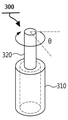
도 3은 일반적인 모터의 기본 개념도이다. 도 3을 참조하면, 모터는 모터 고정자(310)와, 이 고정자(310)내에서 회전하는 모터 회전자(320)로 구성된다. 따라서, 모터 회전자(320)가 회전하면서 회전각(θ)이 발생한다.3 is a basic conceptual diagram of a general motor. Referring to FIG. 3, the motor is composed of a
리졸버는 도 3에 도시된 김발, 모터(전동기) 등의 회전자(320)의 위치와 속도의 정밀 측정에 있어 널리 유용하게 사용하는 장치이다. 이러한 리졸버의 구성 개념을 보여주는 도면이 도 4에 도시된다.The resolver is a device that is widely used in the precise measurement of the position and speed of the
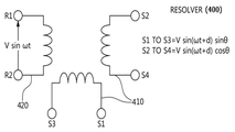
도 4는 도 3에 도시된 모터에 설치되는 리졸버(400)의 개념도이다. 도 4를 참조하면, 회전자(320)의 위치와 속도를 측정하는 데에는 포텐셜 미터, 타코 미터 등이 있지만, 실외 환경에 온도 변화가 심한 환경에서 회로의 강인성 확보와 높은 정밀도를 얻기에는 한계가 있다. 4 is a conceptual diagram of a
여기에서, 리졸버(400)는 수 KHz의 주파수를 갖는 참조용 정현파 신호를 회전자(rotor) 단(R1,R2)에 입력하면 이 리졸버 회전자(420)의 위치에 상응하는 크기를 갖는 자기 유도된 파형이 각각 cos, sin 성분의 고정자(stator) 단(S1,S2,S3,S4)을 통해 출력된다. 이러한 리졸버 회전각 검출기는 리졸버 회전자(420)의 위치에 따라 cos, sin 성분의 고정자 단의 서로 상대적인 출력 값의 차이를 이용하여 회전자의 위치를 탐지하는 장치이다.Here, when the
일반적인 리졸버의 구성을 보면, 회전자 단(R1-R2)은 모터 회전자(320)를 나타내며 제 1 고정자 단(S1-S3)은 sin 성분의 모터 고정자(310)이며 제 2 고정자 단(S4-S2)은 cos 성분의 모터 고정자(310)를 나타낸다. 또한, θ는 리졸버 회전자(420)와 리졸버 고정자(410) 사이에 존재하는 회전자(320)의 위치를 의미하며, d는 리졸버 회전자와 리졸버 고정자 사이에 발생하는 다양한 시간 지연을 표시하며, ω는 각속도를 나타내며, V는 여기 전압(excitation voltage)을 나타낸다.In the structure of a typical resolver, the rotor stages R1-R2 represent the
또한, 리졸버 고정자(410)는 2상 검출 권선으로 이루어지며, 리졸버 회전자(420)는 1상의 여자 권선으로 구성된다. 리졸버 회전자는 회전각에 따라 철심 형상이 변화하여 쇄교자속이 변동하게 된다.In addition, the
일반적으로 회전각 검출기, 리졸버 디지털 변환기(RDC: Resolver-to-Digital Converter)에서는 리졸버 로터 단에 인가된 정현파 신호 기준으로 내부 회로까지 소요되는 시간 지연 값을 추정하고, 시간 동기를 맞추는 과정을 동기화 과정 혹은 “Phase Calibration”처리라고 알려져 있다. In general, a rotation angle detector and a resolver-to-digital converter (RDC) estimate a time delay value to an internal circuit based on a sine wave signal applied to a resolver rotor stage, and synchronize the time synchronization process. Or “Phase Calibration” process.
즉, 본 발명의 일실시예에서는 cos/sin 삼각 함수의 합산(accumulation(4 value summation)), 곱(product), 제곱 연산(square) 특성을 이용하여 RDC에서 꼭 필요로 하는 "위상 교정(Phase Calibration)”처리 과정을 제거하고 있다. value summation은 4 오버 샘플링된 신호를 4번 누적해서 합산한다는 의미이다. 이는 사인/코사인 성분을 없애는데 있다.That is, in one embodiment of the present invention, "Phase correction", which is necessary for RDC, is required by using the sum of cos / sin trigonometric function (4 value summation), a product, and a square operation. “Calibration” is eliminated. Value summation means 4 cumulative oversumming of 4 oversampled signals to eliminate sine / cosine components.
도 5는 본 발명의 일실시예에 따른 비동기 리졸버 회전각 검출기를 구성하는 리졸버 디지털 변환기(RDC: Resolver-to-Digital Converter)코사인 모듈(500)의 구성 블럭도이다. 도 5를 참조하면, 리졸버 코사인(cos) 고정자 단(S2,S4)에 해당된 입력 신호는 리졸버 디지털 변환기(RDC: Resolver-to-Digital Converter) 코사인 모듈(500)로 인가되며, 리졸버 디지털 변환기 코사인 모듈(500)은 리졸버 코사인(cos) 고정자 단(S2,S4)에 포함된 f(=w/2*π) Hz 주파수를 갖는 정현파 성분과 리졸버 부품, RDC 처리 과정에 내재된 시간 지연값을 제거하고, 단지 코사인 고정자 단(S2,S4)에서 필요로 하는 cos(θ) 성분만 출력한다.FIG. 5 is a block diagram illustrating a resolver-to-digital converter (RDC)
세부적으로 리졸버 디지털 변환기(RDC: Resolver-to-Digital Converter)코사인 모듈(500)은 리졸버 코사인(cos) 고정자 단(S2,S4)에 인가된 입력 신호(V sin(wt + d) cosθ)를 먼저 ADC(Analog-to-Digital Converter)(510)를 통해 디지털 부호화를 수행한다. 이를 수식으로 나타내면 다음과 같다.In detail, the resolver-to-digital converter (RDC)
[수학식 1][Equation 1]
A sin(w/N*n + d) cos(θ)A sin (w / N * n + d) cos (θ)
여기서, A는 리졸버 코사인 고정자 단에서 측정된 신호 크기, w는 각속도, N은 4의 배수의 값을 가지며 w의 오버샘플링(oversampling) 크기를 나타내며, n은 이산 시간 변수(discrete time variable)로서 일반적으로 사용되는 시간 변수(t)의 이산 버전을 나타내며, d는 리졸버(400)의 리졸버 회전자와 리졸버 고정자 사이에 발생하는 시간 지연값을 나타낸다. Where A is the magnitude of the signal measured at the resolver cosine stator stage, w is the angular velocity, N is a multiple of 4, and is an oversampling magnitude of w, and n is a discrete time variable. A discrete version of the time variable t is used as d, and d represents a time delay value occurring between the resolver rotor and the resolver stator of the
ADC(510)에서의 ADC 샘플링(획득) 주파수는 임의의 N(4의 배수)로 하여 정현파 신호의 한 주기에 맞추도록 한다. 그리고, ADC 출력 신호는 N/4 주기를 갖는 누적(summation) 회로(520)를 통해 LPF(Low Pass Filter) 처리를 수행한다. 부연하면, 제 1 누적(summation) 회로(520)는 ADC(510)의 결과값을 이용하여 N/4주기마다 누적한다.The ADC sampling (acquisition) frequency in the
제 1 및 제 2 곱셈기(530,535)는 cos/sin 삼각 함수의 특성을 이용하여 제 1 누적 회로(520)에 의해 생성된 출력 신호를 2가지 경로로 생성한다. 즉, 제 1 곱셈기(530)에서는 제 1 누적 회로(520)에 의해 생성된 출력 신호에 sin 곱하기 연산 처리가 수행되고, 제 2 곱셈기(535)에서는 제 1 누적 회로(520)에 의해 생성된 출력 신호에 cos 곱하기 연산 처리가 수행된다. The first and
일반적으로 1주기를 갖는 정현파에 대해 4 오버 샘플링한다면 각각 45도, 135, 225도, 315도가 된다. 각각의 해당된 각도에서의 사인 함수 값은 각각 +1/sqrt(2), +1/sqrt(2), -1/sqrt(2), -1/sqrt(2)이 된다. 그런데, RDC에서는 두 고정자 사이의 각도만 추출하는 것이기 때문에 이 1/sqrt(2) 스케일링 계수를 편의상 제거할 수 있다. 따라서, 본 발명의 일실시예에서는 단순히 +1, +1, -1, -1로 표시하고 있다.In general, four oversampling of a sinusoidal wave having one cycle results in 45 degrees, 135, 225 degrees, and 315 degrees, respectively. The sine function at each corresponding angle is + 1 / sqrt (2), + 1 / sqrt (2), -1 / sqrt (2) and -1 / sqrt (2), respectively. However, since the RDC extracts only the angle between the two stators, this 1 / sqrt (2) scaling factor can be removed for convenience. Therefore, in one embodiment of the present invention, it is simply indicated as +1, +1, -1, -1.
제 2-1 누적 회로(540)는 곱하기에 대한 삼각함수 특성을 이용하여 cos(![]()
![]()
![]()
![]()
![]()
![]()
![]()
![]()
![]()
![]()
![]()
![]()
![]()
![]()
![]()
![]()
이와 유사하게, 제 2 곱셈기(535)에 의해 sin(x +![]()
![]()
![]()
![]()
![]()
![]()
![]()
![]()
![]()
![]()
![]()
![]()
여기서, ![]()
![]()
![]()
![]()
제 1 및 제 2 제곱 회로(550,555)는 cos(![]()
![]()
![]()
![]()
![]()
![]()
![]()
![]()
![]()
![]()
![]()
![]()
![]()
![]()
![]()
![]()
한편, 비교 회로(580)는 경계치(0)를 기준으로 해서 입력값, cos(![]()
![]()
특히, 비교 회로(580)에 입력되는 입력 신호는 RDC 회로의 전체 시간 지연(![]()
![]()
제곱근 회로(570)는 합산기(560)의 결과값에 제곱근을 하여 절대치를 씌운다. 즉, │cos(θ)│를 생성한다.The
최종 곱셈기(590)는 제곱근 회로(570)의 결과값에 비교 회로(580)에 의해 산출된 부호를 곱하여 출력한다. The
도 6은 본 발명의 일실시예에 따른 비동기 리졸버 회전각 검출기를 구성하는 리졸버 디지털 변환기(RDC: Resolver-to-Digital Converter)사인 모듈(600)의 구성 블럭도이다. 도 6을 참조하면, 리졸버 사인(sin) 고정자 단(S1,S2)에 해당된 입력 신호는 리졸버 디지털 변환기(RDC: Resolver-to-Digital Converter) 사인 모듈(600)로 인가되며, 리졸버 디지털 변환기 사인 모듈(600)은 리졸버 사인(sin) 고정자 단(S1,S3)에 포함된 f(=w/2*π) Hz 주파수를 갖는 정현파 성분과 리졸버 부품 및 RDC 처리 과정에 내재된 시간 지연값(d)을 제거하고, 단지 사인 고정자 단(S1,S3)에서 필요로 하는 sin(θ) 성분만 출력한다.FIG. 6 is a block diagram illustrating a resolver-to-digital converter (RDC)
세부적으로 리졸버 디지털 변환기(RDC: Resolver-to-Digital Converter) 사인 모듈(600)은 리졸버 코사인(cos) 고정자 단(S1,S3)에 인가된 입력 신호(V sin(wt + d) sinθ)를 먼저 ADC(Analog-to-Digital Converter)(610)를 통해 디지털 부호화를 수행한다. 이를 수식으로 나타내면 다음과 같다.In detail, the resolver-to-digital converter (RDC)
[수학식 2][Equation 2]
A sin(w/N*n + d) sin(θ)A sin (w / N * n + d) sin (θ)
ADC(610)에서의 ADC 샘플링(획득) 주파수는 임의의 N(4의 배수)로 하여 정현파 신호의 한 주기에 맞추도록 한다. 그리고, ADC 출력 신호는 N/4 주기를 갖는 누적(summation) 회로(620)를 통해 LPF(Low Pass Filter) 처리를 수행한다. 부연하면, 제 1 누적(summation) 회로(620)는 ADC(610)의 결과값을 이용하여 N/4주기마다 누적한다.The ADC sampling (acquisition) frequency in the
제 1 및 제 2 곱셈기(630,635)는 cos/sin 삼각 함수의 특성을 이용하여 제 1 누적 회로(620)에 의해 생성된 출력 신호를 2가지 경로로 생성한다. 즉, 제 1 곱셈기(630)에서는 제 1 누적 회로(620)에 의해 생성된 출력 신호에 sin 곱하기 연산 처리가 수행되고, 제 2 곱셈기(635)에서는 제 1 누적 회로(620)에 의해 생성된 출력 신호에 cos 곱하기 연산 처리가 수행된다. The first and
제 2-1 누적 회로(640)는 곱하기에 대한 삼각함수 특성을 이용하여 cos(![]()
![]()
![]()
![]()
![]()
![]()
![]()
![]()
![]()
![]()
![]()
![]()
![]()
![]()
![]()
![]()
이와 유사하게, 제 2 곱셈기(635)에 의해 sin(x +![]()
![]()
![]()
![]()
![]()
![]()
![]()
![]()
![]()
![]()
![]()
![]()
여기서, ![]()
![]()
![]()
![]()
제 1 및 제 2 제곱 회로(650,655)는 cos(![]()
![]()
![]()
![]()
![]()
![]()
![]()
![]()
![]()
![]()
![]()
![]()
![]()
![]()
![]()
![]()
한편, 비교 회로(680)는 경계치(0)를 기준으로 해서 입력값, cos(![]()
![]()
특히, 비교 회로(680)에 입력되는 입력 신호는 RDC 회로의 전체 시간 지연(![]()
![]()
제곱근 회로(670)는 합산기(660)의 결과값에 제곱근을 하여 절대치를 씌운다. 즉, │sin(θ)│를 생성한다.The
최종 곱셈기(690)는 제곱근 회로(670)의 결과값에 비교 회로(680)에 의해 산출된 부호를 곱하여 출력한다. The
도 5 및 도 6에 도시된 리졸버 디지털 변환기 코사인 모듈(500)과 리졸버 디지털 변환기 사인 모듈(600)에서 얻는 디지털 부호화된 cos/sin 회전자 결과값은 CPU(Central Processing Unit), DSP(Digital Signal Processor), 혹은 FPGA H/W(Hardware)을 이용하여 arctan(·) 연산을 통해 최종적인 회전각이 산출된다. 회전각을 계산하는 기술은 널리 공지되어 있으므로 본 발명의 명확한 이해를 더 이상의 설명은 생략하기로 한다.The result of the digitally encoded cos / sin rotor obtained by the resolver digital
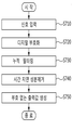
도 7은 본 발명의 일실시예에 따른 비동기 리졸버 회전각 검출 과정을 보여주는 흐름도이다. 도 7을 참조하면, 리졸버(400)가 동작함에 따라 리졸버 디지털 변환기 코사인 모듈(500) 및 리졸버 디지털 변환기 사인 모듈(600)이 리졸버(400)로부터 입력 신호를 인가받는다(단계 S710).7 is a flowchart illustrating a process of detecting an asynchronous resolver rotation angle according to an embodiment of the present invention. Referring to FIG. 7, as the
리졸버 디지털 변환기 코사인 모듈(500) 및 리졸버 디지털 변환기 사인 모듈(600)이 입력 신호를 디지털 부호화한다(단계 S720).The resolver digital
이후, 디지털 부호화된 신호를 일정 주기로 누적하여 필터링을 수행한다(단계 S730). 부연하면, ADC 샘플링(획득) 주파수는 임의의 N(4의 배수)로 하여 정현파 신호의 한 주기에 맞추도록 한다. 이후, ADC 출력 신호는 N/4 주기를 갖도록 누적한 후, LPF(Low Pass Filter) 처리를 수행하여 필터링을 한다.Thereafter, the digitally encoded signal is accumulated at a predetermined period to be filtered (step S730). In other words, the ADC sampling (acquisition) frequency is set to any N (multiple of 4) to match one period of the sinusoidal signal. After that, the ADC output signal is accumulated to have an N / 4 period, and then filtered by performing a low pass filter (LPF) process.
이후, cos/sin 삼각 함수의 특성을 이용하여 출력 신호를 두 가지 경로로 분배하여 각각 cos(![]()
![]()
![]()
![]()
![]()
![]()
![]()
![]()
이후, 최종적으로 부호(+,-)를 추가하여 부호있는 최종 출력값을 생성한다(단계 S750).Then, finally, the sign (+,-) is added to generate a signed final output value (step S750).
또한, 여기에 개시된 실시형태들과 관련하여 설명된 방법 또는 알고리즘의 단계들은, 다양한 컴퓨터 수단을 통하여 수행될 수 있는 프로그램 명령 형태로 구현되어 컴퓨터 판독 가능 매체에 기록될 수 있다. 상기 컴퓨터 판독 가능 매체는 프로그램 (명령) 코드, 데이터 파일, 데이터 구조 등을 단독으로 또는 조합하여 포함할 수 있다. In addition, the steps of a method or algorithm described in connection with the embodiments disclosed herein may be embodied in a program instruction form that can be executed by various computer means and recorded in a computer-readable medium. The computer readable medium may include program (instruction) code, data file, data structure, etc. alone or in combination.
상기 매체에 기록되는 프로그램 (명령) 코드는 본 발명을 위하여 특별히 설계되고 구성된 것들이거나 컴퓨터 소프트웨어 당업자에게 공지되어 사용 가능한 것일 수도 있다. 컴퓨터 판독 가능 기록 매체의 예에는 하드 디스크, 플로피 디스크 및 자기 테이프 등과 같은 자기 매체(magnetic media), CD-ROM, DVD, 블루레이 등과 같은 광기록 매체(optical media) 및 롬(ROM), 램(RAM), 플래시 메모리 등과 같은 프로그램 (명령) 코드를 저장하고 수행하도록 특별히 구성된 반도체 기억 소자가 포함될 수 있다. The program (command) code recorded on the medium may be those specially designed and configured for the present invention, or may be known and available to those skilled in computer software. Examples of computer-readable recording media include magnetic media such as hard disks, floppy disks, and magnetic tapes, optical media such as CD-ROMs, DVDs, Blu-rays, etc., and ROMs and RAMs. Semiconductor memory devices specifically configured to store and execute program (command) code, such as RAM), flash memory, and the like.
여기서, 프로그램 (명령) 코드의 예에는 컴파일러에 의해 만들어지는 것과 같은 기계어 코드뿐만 아니라 인터프리터 등을 사용해서 컴퓨터에 의해서 실행될 수 있는 고급 언어 코드를 포함한다. 상기된 하드웨어 장치는 본 발명의 동작을 수행하기 위해 하나 이상의 소프트웨어 모듈로서 작동하도록 구성될 수 있으며, 그 역도 마찬가지이다.Here, examples of program (instruction) code include not only machine code generated by a compiler, but also high-level language code that can be executed by a computer using an interpreter or the like. The hardware device described above may be configured to operate as one or more software modules to perform the operations of the present invention, and vice versa.
400: 리졸버
500: 리졸버 디지털 변환기 코사인 모듈
510: 제 1 ADC(Analog-Digital Converter)
501: 제 1 전체 시간 지연 산출부
502: 코사인 산출부
580: 제 1 비교부
600: 리졸버 디지털 변환기 사인 모듈
610: 제 1 ADC(Analog-Digital Converter)
601: 제 2 전체 시간 지연 산출부
602: 사인 산출부
680: 제 2 비교부400: resolver
500: resolver digital converter cosine module
510: first analog-digital converter (ADC)
501: First total time delay calculating unit
502: cosine calculation unit
580: first comparison unit
600: resolver digital converter sine module
610: first analog-digital converter (ADC)
601, the second total time delay calculation unit
602: sine calculator
680: second comparison unit
Claims (15)
상기 리졸버(400)로부터 리졸버 코사인(cos) 고정자 단(S2,S4)에 해당되는 제 1 입력 신호를 입력받아 상기 제 1 입력 신호로부터 전체 시간 지연값(
상기 리졸버(400)로부터 리졸버 사인(sin) 고정자 단(S1,S3)에 해당되는 제 2 입력 신호를 입력받아 상기 제 2 입력 신호로부터 전체 시간 지연값(
상기 리졸버 디지털 변환기 코사인 모듈(500)은, 상기 제 1 입력 신호를 제 1 디지털 신호로 변환하는 제 1 ADC(Analog-Digital Converter)(510);
상기 제 1 디지털 신호로부터 상기 전체 시간 지연값을 산출하는 제 1 전체 시간 지연 산출부(501); 및
상기 전체 시간 지연값을 제거하고 제 1 절대치의 코사인 성분만을 산출하는 코사인 산출부(502);를 포함하고,
상기 제 1 전체 시간 지연 산출부(501)는,
상기 제 1 디지털 신호를 미리 설정된 주기로 누적하여 누적 신호를 생성하는 제 1 최초 누적 회로(520);
상기 누적 신호에 미리 설정되는 설정 사인 성분 및 설정 코사인 성분을 곱하기 연산을 통하여 제 1 중간 출력 신호를 각각 생성하는 제 1-1 곱셈기 및 제 1-2 곱셈기(530,535); 및
삼각함수 특성을 이용하여 상기 제 1 중간 출력 신호로부터 상기 전체 시간 지연값을 갖는 코사인 및 모터(300)의 회전각을 갖는 코사인의 제 1 -1 곱(cos(
Resolver 400;
Receiving the first input signal corresponding to the resolver cosine (cos) stator stage (S2, S4) from the resolver 400, the total time delay value from the first input signal (
The second input signal corresponding to the resolver sin stator stages S1 and S3 is received from the resolver 400, and a total time delay value from the second input signal (
The resolver digital converter cosine module 500 includes: a first analog-to-digital converter (ADC) 510 for converting the first input signal into a first digital signal;
A first total time delay calculator (501) for calculating the total time delay value from the first digital signal; And
And a cosine calculator 502 for removing only the total time delay value and calculating only a cosine component of a first absolute value.
The first total time delay calculation unit 501,
A first initial accumulation circuit 520 for accumulating the first digital signal at a predetermined period to generate a cumulative signal;
1-1 multipliers and 1-2 multipliers (530, 535) for generating a first intermediate output signal through a multiplication operation of the set sine component and the set cosine component preset to the accumulated signal; And
The first −1 product of cosine having the total time delay value and the cosine having the rotation angle of the motor 300 from the first intermediate output signal using a trigonometric characteristic (cos (
상기 코사인 산출부(502)는,
상기 제 1-1 곱(cos(
삼각함수 특성을 이용하여 회전각을 갖는 코사인의 제 1 제곱값(cos(θ)2)을 산출하는 제 1 합산기(570); 및
상기 제 1 제곱값을 제곱근 공식을 이용하여 제 1 절대치(│cos(θ)│)로 변환하는 제 1 제곱근 회로(570);를 포함하는 것을 특징으로 하는 비동기 리졸버 회전각 검출기.
The method of claim 1,
The cosine calculation unit 502,
The first-first product (cos (
A first summer 570 that calculates a first square value cos (θ) 2 of the cosine having the rotation angle by using the trigonometric function; And
And a first square root circuit (570) for converting the first square value into a first absolute value (cos (θ) │) using a square root formula.
상기 제 1-1 곱(cos(
상기 양 또는 음의 부호를 상기 제 1 절대치(│cos(θ)│)에 곱 연산을 수행하여 상기 최종 코사인 성분만을 출력하는 제 1 최종 곱셈기(590);를 포함하는 것을 특징으로 하는 비동기 리졸버 회전각 검출기.
The method of claim 4, wherein
The first-first product (cos (
And a first final multiplier 590 for multiplying the positive or negative sign by the first absolute value | cos (θ) │ to output only the final cosine component. Each detector.
상기 리졸버 디지털 변환기 사인 모듈(600)은, 상기 제 2 입력 신호를 제 2 디지털 신호로 변환하는 제 2 ADC(Analog-Digital Converter)(610);
상기 전체 시간 지연값을 산출하는 제 2 전체 시간 지연 산출부(601); 및
상기 전체 시간 지연값을 제거하고 제 2 절대치의 사인 성분만을 산출하는 사인 산출부(602);를 포함하는 것을 특징으로 하는 비동기 리졸버 회전각 검출기.
The method of claim 1,
The resolver digital converter sign module 600 includes: a second analog-to-digital converter (ADC) 610 for converting the second input signal into a second digital signal;
A second total time delay calculator 601 for calculating the total time delay value; And
And a sine calculator (602) for removing the total time delay value and calculating only a sine component of a second absolute value.
상기 제 2 전체 시간 지연 산출부(601)는,
상기 제 2 디지털 신호를 미리 설정된 주기로 누적하여 누적 신호를 생성하는 제 2 최초 누적 회로(620);
상기 누적 신호에 미리 설정되는 설정 사인 성분 및 설정 코사인 성분을 곱하기 연산을 통하여 제 2 중간 출력 신호를 각각 생성하는 제 2-1 및 제 2-2 곱셈기(630,635); 및
삼각함수 특성을 이용하여 상기 중간 출력 신호로부터 상기 전체 시간 지연값을 갖는 코사인 및 모터(300)의 회전각을 갖는 사인의 제 2 -1 곱(cos(
The method of claim 6,
The second total time delay calculation unit 601,
A second initial accumulation circuit 620 for accumulating the second digital signal at a predetermined period to generate a cumulative signal;
2-1 and 2-2 multipliers (630, 635) for generating a second intermediate output signal by multiplying the accumulated signal by a preset sine component and a preset cosine component; And
By using the trigonometric characteristic, the second -1 product of cosine having the total time delay value and the sine having the rotation angle of the motor 300 from the intermediate output signal (cos (
상기 사인 산출부(602)는,
상기 제 2-1 곱(cos(
상기 삼각함수 특성을 이용하여 회전각을 갖는 사인의 제 2 제곱값(sin(θ)2)을 산출하는 제 2 합산기(670); 및
상기 제 2 제곱값을 제곱근 공식을 이용하여 제 2 절대치(│sin(θ)│)로 변환하는 제 2 제곱근 회로(670);를 포함하는 것을 특징으로 하는 비동기 리졸버 회전각 검출기.
The method of claim 7, wherein
The sine calculation unit 602,
The 2-1 product (cos (
A second summer 670 for calculating a second squared value sin (θ) 2 of a sine having a rotation angle by using the trigonometric function; And
And a second square root circuit (670) for converting the second square value into a second absolute value (sin (θ) |) using a square root formula.
상기 제 2-1 곱(cos(
상기 양 또는 음의 부호를 상기 제 2 절대치(│sin(θ)│)에 곱 연산을 수행하여 상기 최종 사인 성분만을 출력하는 제 2 최종 곱셈기(690);를 포함하는 것을 특징으로 하는 비동기 리졸버 회전각 검출기.
The method of claim 8,
The 2-1 product (cos (
And a second final multiplier 690 for multiplying the positive or negative sign by the second absolute value | sin ([theta]) and outputting only the final sine component. Each detector.
상기 전체 시간 지연값(
The method of claim 1,
The total time delay value (
상기 시간 지연값(d)은 특정 주파수 f(=w/2*π) Hz(여기서, w는 각속도를 나타낸다)를 갖는 정현파 성분과 리졸버 자체에 따른 지연값인 것을 특징으로 하는 비동기 리졸버 회전각 검출기.
The method of claim 10,
The time delay value d is a sine wave component having a specific frequency f (= w / 2 * π) Hz (where w represents an angular velocity) and a delay value according to the resolver itself. .
상기 제 1 ADC(510)는 프로그래밍 주문형 IC(Integrated Circuit)에 통합되는 것을 특징으로 하는 비동기 리졸버 회전각 검출기.
The method of claim 1,
And said first ADC (510) is integrated into a programmable integrated circuit (IC).
상기 제 2 ADC(610)는 프로그래밍 주문형 IC(Integrated Circuit)에 통합되는 것을 특징으로 하는 비동기 리졸버 회전각 검출기.
The method of claim 6,
And said second ADC (610) is integrated into a programmable integrated circuit (IC).
(a) 리졸버 디지털 변환기 코사인 모듈(500)이 리졸버(400)로부터 리졸버 코사인(cos) 고정자 단(S2,S4)에 해당되는 제 1 입력 신호를 입력받아 상기 제 1 입력 신호로부터 전체 시간 지연값(
(b) 리졸버 디지털 변환기 사인 모듈(600)이 상기 리졸버(400)로부터 리졸버 사인(sin) 고정자 단(S1,S3)에 해당되는 제 2 입력 신호를 입력받아 상기 제 2 입력 신호로부터 전체 시간 지연값(
상기 리졸버 디지털 변환기 코사인 모듈(500)은, 상기 제 1 입력 신호를 제 1 디지털 신호로 변환하는 제 1 ADC(Analog-Digital Converter)(510);
상기 제 1 디지털 신호로부터 상기 전체 시간 지연값을 산출하는 제 1 전체 시간 지연 산출부(501); 및
상기 전체 시간 지연값을 제거하고 제 1 절대치의 코사인 성분만을 산출하는 코사인 산출부(502);를 포함하고,
상기 제 1 전체 시간 지연 산출부(501)는,
상기 제 1 디지털 신호를 미리 설정된 주기로 누적하여 누적 신호를 생성하는 제 1 최초 누적 회로(520);
상기 누적 신호에 미리 설정되는 설정 사인 성분 및 설정 코사인 성분을 곱하기 연산을 통하여 제 1 중간 출력 신호를 각각 생성하는 제 1-1 곱셈기 및 제 1-2 곱셈기(530,535); 및
삼각함수 특성을 이용하여 상기 제 1 중간 출력 신호로부터 상기 전체 시간 지연값을 갖는 코사인 및 모터(300)의 회전각을 갖는 코사인의 제 1-1 곱(cos(
In the asynchronous resolver rotation angle detection method,
(a) The resolver digital converter cosine module 500 receives a first input signal corresponding to the resolver cosine stator stages S2 and S4 from the resolver 400 and receives a total time delay value from the first input signal.
(b) The resolver digital converter sine module 600 receives a second input signal corresponding to the resolver sin stator stages S1 and S3 from the resolver 400 and receives a total time delay value from the second input signal. (
The resolver digital converter cosine module 500 includes: a first analog-to-digital converter (ADC) 510 for converting the first input signal into a first digital signal;
A first total time delay calculator (501) for calculating the total time delay value from the first digital signal; And
And a cosine calculator 502 for removing only the total time delay value and calculating only a cosine component of a first absolute value.
The first total time delay calculation unit 501,
A first initial accumulation circuit 520 for accumulating the first digital signal at a predetermined period to generate a cumulative signal;
1-1 multipliers and 1-2 multipliers (530, 535) for generating a first intermediate output signal through a multiplication operation of the set sine component and the set cosine component preset to the accumulated signal; And
Using a trigonometric characteristic, a cosine having the total time delay from the first intermediate output signal and a 1-1 product of cosine having the rotation angle of the motor 300 (cos (
A computer-readable storage medium storing program code for executing the asynchronous resolver rotation angle detection method according to claim 14.
Priority Applications (1)
| Application Number | Priority Date | Filing Date | Title |
|---|---|---|---|
| KR1020180082854A KR102051820B1 (en) | 2018-07-17 | 2018-07-17 | Apparatus for detecting rotation angle of a asynchronous resolver and Method thereof |
Applications Claiming Priority (1)
| Application Number | Priority Date | Filing Date | Title |
|---|---|---|---|
| KR1020180082854A KR102051820B1 (en) | 2018-07-17 | 2018-07-17 | Apparatus for detecting rotation angle of a asynchronous resolver and Method thereof |
Publications (1)
| Publication Number | Publication Date |
|---|---|
| KR102051820B1 true KR102051820B1 (en) | 2019-12-04 |
Family
ID=69004226
Family Applications (1)
| Application Number | Title | Priority Date | Filing Date |
|---|---|---|---|
| KR1020180082854A KR102051820B1 (en) | 2018-07-17 | 2018-07-17 | Apparatus for detecting rotation angle of a asynchronous resolver and Method thereof |
Country Status (1)
| Country | Link |
|---|---|
| KR (1) | KR102051820B1 (en) |
Citations (7)
| Publication number | Priority date | Publication date | Assignee | Title |
|---|---|---|---|---|
| KR20090021461A (en) * | 2007-08-27 | 2009-03-04 | 평택대학교 산학협력단 | Resolver to digital converter |
| JP2011033602A (en) * | 2009-08-06 | 2011-02-17 | Mitsubishi Electric Corp | Resolver/digital converter, and resolver/digital conversion method |
| WO2011068196A1 (en) * | 2009-12-04 | 2011-06-09 | 本田技研工業株式会社 | Resolver digital converter |
| JP2011141207A (en) * | 2010-01-07 | 2011-07-21 | Kawasaki Heavy Ind Ltd | Resolver signal conversion device and method |
| JP2012058007A (en) | 2010-09-07 | 2012-03-22 | Tamagawa Seiki Co Ltd | Method for converting analog signal into digital signal |
| KR20120112704A (en) | 2010-02-23 | 2012-10-11 | 타마가와 세이키 가부시키가이샤 | Method of detecting rotational angle or method of winding for synchronizing device windings |
| JP2013024577A (en) | 2011-07-15 | 2013-02-04 | Mitsubishi Electric Corp | Angle detection method by resolver |
-
2018
- 2018-07-17 KR KR1020180082854A patent/KR102051820B1/en active IP Right Grant
Patent Citations (7)
| Publication number | Priority date | Publication date | Assignee | Title |
|---|---|---|---|---|
| KR20090021461A (en) * | 2007-08-27 | 2009-03-04 | 평택대학교 산학협력단 | Resolver to digital converter |
| JP2011033602A (en) * | 2009-08-06 | 2011-02-17 | Mitsubishi Electric Corp | Resolver/digital converter, and resolver/digital conversion method |
| WO2011068196A1 (en) * | 2009-12-04 | 2011-06-09 | 本田技研工業株式会社 | Resolver digital converter |
| JP2011141207A (en) * | 2010-01-07 | 2011-07-21 | Kawasaki Heavy Ind Ltd | Resolver signal conversion device and method |
| KR20120112704A (en) | 2010-02-23 | 2012-10-11 | 타마가와 세이키 가부시키가이샤 | Method of detecting rotational angle or method of winding for synchronizing device windings |
| JP2012058007A (en) | 2010-09-07 | 2012-03-22 | Tamagawa Seiki Co Ltd | Method for converting analog signal into digital signal |
| JP2013024577A (en) | 2011-07-15 | 2013-02-04 | Mitsubishi Electric Corp | Angle detection method by resolver |
Non-Patent Citations (1)
| Title |
|---|
| High-Accuracy All-Digital Resolver-to-Digital Conversion(공개시점 2011.04.19.)* * |
Similar Documents
| Publication | Publication Date | Title |
|---|---|---|
| JP5041419B2 (en) | Resolver device, resolver angle detection device and method | |
| EP2827106B1 (en) | Angle detection device | |
| JP5281102B2 (en) | Resolver device, resolver angle detection device and method | |
| JP6005781B2 (en) | Resolver device | |
| JP5173962B2 (en) | Resolver / digital conversion apparatus and resolver / digital conversion method | |
| CN107342711B (en) | Control device | |
| US10514274B2 (en) | Device and method of estimating rotor angle in motor | |
| JP3893033B2 (en) | Position detection device | |
| Park et al. | A linear compensation method for improving the accuracy of an absolute multipolar magnetic encoder | |
| JP5000441B2 (en) | Power measuring method and power measuring apparatus | |
| JP2014157069A (en) | Position detector | |
| KR102051820B1 (en) | Apparatus for detecting rotation angle of a asynchronous resolver and Method thereof | |
| CN102401664A (en) | Position detector | |
| JP2009025068A (en) | Resolver/digital conversion method, and resolver/digital conversion circuit | |
| JP6205683B2 (en) | Rotation angle detection device, image processing device, and rotation angle detection method | |
| JP2013224865A (en) | Signal processing device | |
| JP6788512B2 (en) | Control device | |
| JP2002541692A (en) | Digital phase sensitive rectification of signals from AC driven transducers | |
| CN110869710B (en) | Measuring method using inductive displacement sensor | |
| JP5823785B2 (en) | Rotation angle detector | |
| JP4470804B2 (en) | Resolver / digital conversion circuit | |
| JP5342982B2 (en) | Resolver digital converter | |
| JP3914818B2 (en) | Rotation angle detector | |
| Neto et al. | Robust positive-sequence detector algorithm | |
| Chen et al. | Design and implementation of a new high-accuracy interpolation encoder IC for magneto-resistive sensors |
Legal Events
| Date | Code | Title | Description |
|---|---|---|---|
| E701 | Decision to grant or registration of patent right | ||
| GRNT | Written decision to grant |