JP3893033B2 - Position detection device - Google Patents
Position detection device Download PDFInfo
- Publication number
- JP3893033B2 JP3893033B2 JP2001199168A JP2001199168A JP3893033B2 JP 3893033 B2 JP3893033 B2 JP 3893033B2 JP 2001199168 A JP2001199168 A JP 2001199168A JP 2001199168 A JP2001199168 A JP 2001199168A JP 3893033 B2 JP3893033 B2 JP 3893033B2
- Authority
- JP
- Japan
- Prior art keywords
- output
- value
- position sensor
- signal
- correction value
- Prior art date
- Legal status (The legal status is an assumption and is not a legal conclusion. Google has not performed a legal analysis and makes no representation as to the accuracy of the status listed.)
- Expired - Fee Related
Links
Images
Classifications
-
- G—PHYSICS
- G01—MEASURING; TESTING
- G01D—MEASURING NOT SPECIALLY ADAPTED FOR A SPECIFIC VARIABLE; ARRANGEMENTS FOR MEASURING TWO OR MORE VARIABLES NOT COVERED IN A SINGLE OTHER SUBCLASS; TARIFF METERING APPARATUS; MEASURING OR TESTING NOT OTHERWISE PROVIDED FOR
- G01D18/00—Testing or calibrating apparatus or arrangements provided for in groups G01D1/00 - G01D15/00
- G01D18/001—Calibrating encoders
-
- G—PHYSICS
- G01—MEASURING; TESTING
- G01D—MEASURING NOT SPECIALLY ADAPTED FOR A SPECIFIC VARIABLE; ARRANGEMENTS FOR MEASURING TWO OR MORE VARIABLES NOT COVERED IN A SINGLE OTHER SUBCLASS; TARIFF METERING APPARATUS; MEASURING OR TESTING NOT OTHERWISE PROVIDED FOR
- G01D5/00—Mechanical means for transferring the output of a sensing member; Means for converting the output of a sensing member to another variable where the form or nature of the sensing member does not constrain the means for converting; Transducers not specially adapted for a specific variable
- G01D5/12—Mechanical means for transferring the output of a sensing member; Means for converting the output of a sensing member to another variable where the form or nature of the sensing member does not constrain the means for converting; Transducers not specially adapted for a specific variable using electric or magnetic means
- G01D5/244—Mechanical means for transferring the output of a sensing member; Means for converting the output of a sensing member to another variable where the form or nature of the sensing member does not constrain the means for converting; Transducers not specially adapted for a specific variable using electric or magnetic means influencing characteristics of pulses or pulse trains; generating pulses or pulse trains
- G01D5/24409—Interpolation using memories
-
- G—PHYSICS
- G01—MEASURING; TESTING
- G01D—MEASURING NOT SPECIALLY ADAPTED FOR A SPECIFIC VARIABLE; ARRANGEMENTS FOR MEASURING TWO OR MORE VARIABLES NOT COVERED IN A SINGLE OTHER SUBCLASS; TARIFF METERING APPARATUS; MEASURING OR TESTING NOT OTHERWISE PROVIDED FOR
- G01D5/00—Mechanical means for transferring the output of a sensing member; Means for converting the output of a sensing member to another variable where the form or nature of the sensing member does not constrain the means for converting; Transducers not specially adapted for a specific variable
- G01D5/12—Mechanical means for transferring the output of a sensing member; Means for converting the output of a sensing member to another variable where the form or nature of the sensing member does not constrain the means for converting; Transducers not specially adapted for a specific variable using electric or magnetic means
- G01D5/244—Mechanical means for transferring the output of a sensing member; Means for converting the output of a sensing member to another variable where the form or nature of the sensing member does not constrain the means for converting; Transducers not specially adapted for a specific variable using electric or magnetic means influencing characteristics of pulses or pulse trains; generating pulses or pulse trains
- G01D5/24471—Error correction
- G01D5/2448—Correction of gain, threshold, offset or phase control
-
- G—PHYSICS
- G01—MEASURING; TESTING
- G01D—MEASURING NOT SPECIALLY ADAPTED FOR A SPECIFIC VARIABLE; ARRANGEMENTS FOR MEASURING TWO OR MORE VARIABLES NOT COVERED IN A SINGLE OTHER SUBCLASS; TARIFF METERING APPARATUS; MEASURING OR TESTING NOT OTHERWISE PROVIDED FOR
- G01D5/00—Mechanical means for transferring the output of a sensing member; Means for converting the output of a sensing member to another variable where the form or nature of the sensing member does not constrain the means for converting; Transducers not specially adapted for a specific variable
- G01D5/12—Mechanical means for transferring the output of a sensing member; Means for converting the output of a sensing member to another variable where the form or nature of the sensing member does not constrain the means for converting; Transducers not specially adapted for a specific variable using electric or magnetic means
- G01D5/244—Mechanical means for transferring the output of a sensing member; Means for converting the output of a sensing member to another variable where the form or nature of the sensing member does not constrain the means for converting; Transducers not specially adapted for a specific variable using electric or magnetic means influencing characteristics of pulses or pulse trains; generating pulses or pulse trains
- G01D5/24471—Error correction
- G01D5/2449—Error correction using hard-stored calibration data
Landscapes
- Physics & Mathematics (AREA)
- General Physics & Mathematics (AREA)
- Transmission And Conversion Of Sensor Element Output (AREA)
- Length Measuring Devices With Unspecified Measuring Means (AREA)
Description
【0001】
【発明の属する技術分野】
本発明は、測定変位に対応して周期的に変化する90度位相の異なる2つの信号を出力とする位置センサーからの信号に含まれるオフセットや2つの信号の振幅差又は位相差によって生じる位置検出誤差を除去することができる高精度な位置検出装置に関する。
【0002】
【従来の技術】
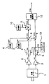
図2は従来の位置検出装置の一例を示すブロック図である。同図において位置センサー1は1相励磁2相出力型の軸倍角100Xのレゾルバであり、入力軸が回転するとレゾルバによって励磁信号が回転量の正弦値と余弦値に振幅変調され、増幅器2,3によって増幅された信号AS,ACが出力される。図2の例では励磁信号の周波数は50KHzであり、位置センサー1の入力軸の回転角をθ、出力信号の振幅をGとすると、信号AS,ACは次の数1,数2で表すことができる。
【数1】
AS=G・SIN(100θ)SIN(2・π・50000・t)
【数2】
AC=G・COS(100θ)SIN(2.π・50000・t)
【0003】
これらの信号AS,ACは、タイミングコントローラ13からの励磁信号に同期して出力される周期20μSのパルス信号TIMによって、それぞれAD変換器4,5によりSIN(100000πt)=1となるタイミングでサンプリングかつデジタル化され、それぞれ数値DS,DCに変換される。したがって数値DS,DCはそれぞれ下記数3,数4のように表すことができ、位置センサー1からはあたかも測定変位θに対応して周期的に変化する90度位相の異なる2つの信号が出力されていると見なすことができる。
【数3】
DS=G・SIN(100θ)
【数4】
DC=G・COS(100θ)
【0004】
上記デジタル化された2つの数値DS,DCには、実際は位置センサーの製品バラツキや信号増幅器等によるオフセット電圧と振幅差が含まれるため、前記数3,数4は厳密には次の数5,数6となる。
【数5】
DS=B・G・SIN(100θ)+SOF
【数6】
DC=G・COS(100θ)+COF
【0005】
これらの数値DS,DCに含まれるオフセット値SOF,COFや2つの信号の振幅比を示す振幅修正値BAJ(=1/B)は、位置検出装置の製造時に測定し、位置検出装置に搭載した不揮発性メモリ等に記憶され、位置検出開始前にそれぞれ記憶器6,7,10に設定される。減算器8,9では数値DS,DCからそれぞれ記憶器6,7が記憶するオフセット値SOF,COFが除去され、数値DSA,DCAとなる。数値DSAはさらに乗算器11で記憶器10が記憶する振幅修正値BAJと乗算され、数値DCAの振幅とほぼ等しい振幅の数値DSBとなる。
【0006】
数値DSBとDCAは、内挿演算器12で2変数を入力とする逆正接演算が行われ、位置センサー1の入力軸の1/100回転内の回転量を示す位置信号POSに変換される。この後、本発明の説明上必要性が無いため図示していないが、実際の位置検出装置では、位置信号POSの変化を基にしたインクリメンタル処理等により、少なくとも位置センサー1入力軸の1回転以上の位置データが求められる。
【0007】
【発明が解決しようとする課題】
一般に工作機械の可動部等を移動させる場合、位置検出装置が検出した位置情報により位置制御を行うだけでなく、位置情報の差分から求めた速度情報をもとに電動機の速度フィードバック制御が行われている。特に、最近では機械の応答性能を上げるため、速度フィードバックのループ利得を高める傾向にある。上述した従来の位置検出装置では製造直後の位置センサーの出力信号に含まれるオフセットや振幅差は除去できるが、製造後の経時変化や位置センサーの設置環境によって生じる上記オフセットや振幅差の変化に起因する位置検出誤差は除去できない。すなわち、位置検出装置製造後にも周囲温度の変化や位置センサーを構成する部材の変化あるいは位置検出装置を組み込む電動機が発する漏れ磁束等によってオフセットや振幅差は微妙な変化を生じる。このような経時変化や設置環境によるオフセットや振幅誤差の除去は、図2の位置検出装置ではできなかった。
【0008】
また、従来の位置検出装置では、製造時のオフセットや振幅修正値の測定方法としては、位置センサーからの出力信号の最大値と最小値を測定して、それらの平均と差からオフセットと振幅を求める方法が一般的であった。或いは、特開平5−256638のように特定条件を満たす複数の位置での位置センサー出力信号の値から演算によりオフセットと振幅を求めていた。これらの方法では、特定の位置での位置センサー出力信号の値を用いるためノイズや波形歪み等の影響を受けやすく、位置検出装置の製造時にオフセットや振幅修正値を精度良く測定できないと言う問題もあった。これらのほか、図2の従来例では説明しなかったが、位置センサー出力信号には、2つの信号の位相差が90度に対して僅かな位相誤差を含む場合があり、この位相差を修正する場合も、オフセット値や振幅差を修正する場合と同様の問題があった。
【0009】
通常、オフセットや振幅差あるいは位相差の経時変化または出荷時の測定誤差よる工作機械等の加工精度に与える影響はほとんど無視することができるほど小さい。しかし、これらの誤差により生じる位置検出誤差は、位置センサーの出力信号の変化と同じサイクル又は2倍のサイクルをもった誤差となるため、可動部の移動速度によってはこの誤差によって生じる速度リップルの周波数と機械共振周波数とが一致し、共振箇所から異音が発生するという問題があった。特に、この異音は速度フィードバックのループ利得の大きさに比例して大きくなるため、異音のためにループ利得を上げられず機械性能を低下させる原因の一つとなっていた。この問題は従来例に上げたレゾルバに限らず光学式エンコーダや磁気式エンコーダにおいても、測定変位に対応して周期的に変化する90度異なる2の信号から内挿処理によって位置を求める限り、同様の問題があった。
【0010】
本発明は、上述した問題点を解消するためになされたもので、本発明の目的は、測定変位に対応して周期的に変化する各々位相の異なる複数の信号を出力とする位置センサーの出力信号に含まれるオフセットや振幅差や位相差の経時変化又は設置環境によって生じる周期性のある位置検出誤差を低減させた高精度な位置検出装置を提供し、工作機械等の可動部の応答性を向上させることにある。
【0011】
【課題を解決するための手段】
本発明は、測定変位に対応して周期的に変化する90度位相の異なる2つの信号を出力とする位置センサーからの出力信号を位置情報に変換する位置検出装置に関するものであり、本発明の上記目的は、オフセット記憶器18,19と、前記位置センサーの2つの出力値からそれぞれ前記オフセット記憶器18,19が記憶するオフセット値を除去するオフセット減算器8,9と、前記オフセット減算器8,9の2つの出力値を位置信号に変換する内挿演算器12と、前記位置センサーによって検出される変位の変化した距離に対応する移動距離を演算する距離演算手段と、前記位置センサーの2つの出力値と前記距離演算手段の出力値に基づきそれぞれ積分する積分手段と、前記積分手段の2つの出力値と前記距離演算手段の出力値に基づきそれぞれオフセット値を演算するオフセット値演算手段と、前記位置センサー出力信号の一周期の整数倍変化後に、前記オフセット値演算手段の出力値を前記オフセット記憶器18,19に記憶指令するオフセット記憶指令手段とを具備することによって達成される。
【0012】
また、本発明の上記目的は、オフセット記憶器18,19と、前記位置センサーの2つの出力値からそれぞれ前記オフセット記憶器18,19が記憶するオフセット値を除去するオフセット減算器8,9と、前記オフセット減算器8,9の2つの出力値を位置信号に変換する内挿演算器12と、前記位置センサーの2つの出力値をそれぞれ記憶する信号記憶器37,38と、前記2つの出力値に対してそれぞれ前記信号記憶器37,38の記憶値との差の自乗を演算し、自乗演算後の2つの値を加算した値の平方根を演算する距離演算器39と、前記距離演算器39の出力値を積算する距離積算器35と、前記位置センサーの2つの出力値をそれぞれ前記距離演算器39の出力値と乗算する信号乗算器22,23と、前記信号乗算器22,23の2つの出力値をそれぞれ積算する信号積算器24,25と、前記距離演算器39の出力値が一定値を越えた場合に、前記信号記憶器37,38と前記信号積算器24,25にそれぞれ記憶指令と積算指令を行う指令手段と、前記信号積算器24,25の2つの出力値それぞれに対して前記距離積算器35の出力値で除算する除算器26,27と、前記位置センサー出力信号の一周期の整数倍変化後に、前記除算器26,27の2つの出力値を前記オフセット記憶器18,19に記憶指令するオフセット記憶指令手段とを具備することで達成される。
【0013】
また、本発明の上記目的は、振幅修正値を記憶する振幅修正値記憶器20と、前記位置センサーの一方の出力信号を前記振幅修正値記憶器20が記憶する振幅修正値に従って信号振幅を修正する乗算器11と、前記位置センサーの他方の出力値と前記信号振幅を修正する乗算器11の出力値を位置信号に変換する内挿演算器12と、前記位置センサーによって検出される変位の変化した距離に対応する移動距離を演算する距離演算手段と、前記位置センサーの2つの出力値をそれぞれ正数化の演算を行う正数化演算器28,29と、前記正数化演算器28,29の2つの出力値と前記距離演算手段の出力値に基づきそれぞれ積算する正数化積算器30,31と、前記正数化積算器30,31の出力値と前記距離演算手段の出力値に基づき振幅修正値を演算する振幅修正値演算手段と、前記位置センサー出力信号の半周期の整数倍変化後に、振幅修正値演算手段の出力値を前記振幅修正値記憶器20に記憶指令する振幅修正値記憶指令手段とを具備することで達成される。
【0014】
また、本発明の上記目的は、振幅修正値を記憶する振幅修正値記憶器20と、前記位置センサーの一方の出力信号を前記振幅修正値記憶器20が記憶する振幅修正値に従って信号振幅を修正する乗算器11と、前記位置センサーの他方の出力値と前記信号振幅を修正する乗算器11の出力値を位置信号に変換する内挿演算器12と、前記位置センサーの2つの出力値をそれぞれ記憶する信号記憶器37,38と、前記位置センサーの2つの出力値に対してそれぞれ前記信号記憶器37,38の記憶値との差の自乗を演算し、自乗演算後の2つの値を加算した値の平方根を演算する距離演算器39と、前記距離演算器39の出力値を積算する距離積算器35と、前記位置センサーの2つの出力値に対してそれぞれ自乗した後に前記距離演算器39の出力値との積を演算する正数化演算器28,29と、前記正数化演算器28,29の2つの出力値をそれぞれ積算する正数化積算器30,31と、前記距離演算器39の出力値が一定値を越えた場合に、前記信号記憶器37,38と前記正数化積算器30,31にそれぞれ記憶指令と積算指令を行う指令手段と、前記距離積算器35と前記正数化積算器30,31の出力値から振幅修正値を演算する振幅修正値演算手段と、前記位置センサー出力信号の半周期の整数倍変化後に、振幅修正値演算手段の出力値を前記振幅修正値記憶器20に記憶指令する振幅修正値記憶指令手段とを具備することで達成される。
【0015】
また、本発明の上記目的は、位相差修正値を記憶する位相差修正値記憶器21と、前記位相差修正値記憶器21が記憶する位相差修正値と前記位置センサーの一方の出力信号に応じて、前記位置センサーの他方の出力信号位相を修正する位相修正手段と、前記位置センサーの一方の出力値と前記位相修正手段の出力値から位置信号に変換する内挿演算器12と、前記位置センサーによって検出される変位の変化した距離に対応する移動距離を演算する距離演算手段と、前記位置センサーの2つの出力値をそれぞれ乗算する相関演算器33と、前記相関演算器33の出力値と前記距離演算手段の出力値に基づき積算する相関積算器34と、前記相関積算器34の出力値と前記距離演算手段の出力値に基づき前記位相差修正値を演算する位相差修正値演算手段と、前記位置センサー出力信号の半周期の整数倍変化後に、前記位相差修正値演算手段の出力値を前記位相修正値記憶器21に記憶指令する位相修正値記憶指令手段とを具備することで達成される。
【0016】
また、本発明の上記目的は、位相差修正値を記憶する位相差修正値記憶器21と、前記位相差修正値記憶器21が記憶する位相差修正値と前記位置センサーの一方の出力信号に応じて、前記位置センサーの他方の出力信号位相を修正する位相修正手段と、前記位置センサーの一方の出力値と前記位相修正手段の出力値から位置信号に変換する内挿演算器12と、前記位置センサーの2つの出力値をそれぞれ記憶する信号記憶器37,38と、前記位置センサーの2つの出力値に対してそれぞれ前記信号記憶器37,38の記憶値との差の自乗を演算し、自乗演算後の2つの値を加算した値の平方根を演算する距離演算器39と、前記距離演算器39の出力値を積算する距離積算器35と、前記位置センサーの2つの出力値の積に前記距離演算器39の出力値を乗算する相関演算器33と、前記相関演算器33の出力値を積算する相関積算器34と、前記距離演算器39の出力値が一定の値を越えた場合に、前記信号記憶器37,38と前記相関積算器34にそれぞれ記憶指令と積算指令を行う指令手段と、前記距離積算器35と前記相関積算器34の出力値から前記位相差修正値を演算する位相差修正値演算手段と、前記位置センサー出力信号の半周期の整数倍変化後に前記位相差修正値演算手段の出力値を前記位相修正値記憶器21に記憶指令する位相修正値記憶指令手段とを具備することで達成される。
【0017】
本発明の位置検出装置では、位置センサー出力信号のオフセット値、振幅修正値、位相修正値を位置センサーがさまざまな位置で出力する信号を活用し、自動的に求めるため、信号ノイズや波形歪みの影響を受けにくく、精度の高いオフセット値,振幅修正値,位相修正値を検出することができ、位置センサー出力信号をこれらの値により修正することにより、高精度な位置検出が可能となる。
【0018】
【発明の実施の形態】
本発明は、位置センサの回転変位を微小回転変位(増分)ごとに分割して考え、位置センサ出力信号の一周期の整数倍または半周期の整数倍で観察することで、製造後のオフセットや振幅修正値の経時変化がとらえられ演算できるということに基づいている。例えば正弦波の関数である出力信号がその一周期変化したときに、その微小回転変位について出力信号を順次積分すると、オフセットがなければ積分値はゼロになるし、ゼロにならないときはその一周期にわたる積分値がオフセット値になる。同様に正弦波の関数である出力信号がその半周期変化したときに、微小回転変位について出力信号の自乗を順次積分し、先ほど求まったオフセット値に対応する量を差し引いてやれば、その値は実効値になり、二つの出力信号について実効値の比を求めれば、振幅修正値が得られる等である。
【0019】
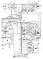
以下、図面に基づいて本発明の実施の形態を説明する。図1は、本発明の位置検出装置の実施の形態を、図2に対応させて示すブロック図であり、図2と同じ機能のものは同じ符号とし、その説明を省略する。
【0020】
まず、図1の位置検出装置では、位置センサー1からの出力信号をデジタル化した数値DS,DCを、平均化処理器14、15により数7,数8の演算で示す平均化処理が行われる。
【数7】
ADS(n)=(DS−ADS(n−1))/N+ADS(n−1)
【数8】
ADC(n)=(DC−ADC(n−1))/N+ADC(n−1)
数7,数8でnとNは信号SUMの立ち上がり変化時に0に初期化され、信号TIMの立ち上がり変化にしたがって1づつインクリメントされる数である。また、Nはnが256以上のときN=256に固定される。なお、ADS(n),ADC(n)はn回目の数値ADS,ADCを意味し、ADS(0)=ADC(0)=0である。
【0021】
次に、平均化処理器14,15によって平均化された位置センサー1からの出力値ADS,ADCは、それぞれ記憶器37,38に信号SUMの立ち上がり変化時に記憶され、記憶器37,38の記憶値DSD,DCDと数値ADS,ADCは距離演算器39により数9の演算が行われ数値DSTが出力される。
【数9】
DST=SQRT((ADS−DSD)^2+(ADC−DCD)^2)
ここで、数値DSTは、信号SUMが入力してから測定変位の変化した距離にほぼ比例した値を示している。数値DSTは、比較器41で記憶器40が記憶する数値DSCと比較され、数値DSTが数値DSCを越えた場合に比較器41の出力信号SMは0から1に立ち上がり変化する。ここでDSCは位置センサー1の入力軸が軸倍角分の1回転よりも十分小さい回転距離動いたときの数値DSTに相当する数値が予め設定されている。信号SMが立ち上がり変化すると、論理和回路52を経由して、信号SUMとして記憶器37,38とすべての積算器にそれぞれ記憶指令と積算指令を行う。
【0022】
このようにして、微小回転変位DSCごとに信号SUMが立上がり変化するので、信号SUMを基準にして、以下の微小回転変位ごとの演算を進めることができる。
【0023】
また、数値DSTは積算器35で信号SUMの立ち上がり変化時に積算され、積算器35は信号CLの立ち下がり変化で0に初期化される。したがって、積算器35が出力する数値DSTSは、信号CLの立ち下がり変化から位置センサー1の入力軸が回転した移動距離にほぼ比例した数値となる。
【0024】
本発明の第一の実施の形態の中心であるオフセット値の演算について説明する。乗算器22,23では、それぞれ数値ADS,ADCと数値DSTが乗算され、数値SOD,CODとして出力される。数値SOD,CODはそれぞれ積算器24、25で信号SUMの立ち上がり変化時に積算されSOS,COSとして出力される。また積算器24,25は信号CLの立ち下がり変化で0に初期化される。したがって、積算器24,25が出力する数値SOS,COSは、信号CLの立ち下がり変化後の、位置センサー1の2つの出力信号を移動量で積分した値にほぼ比例した数値となる。次に除算器26と27では、それぞれ数値SOS,COSが数値DSTSで除算され、数値SO,COとして出力される。そこで数値SOS,COSを移動量にほぼ比例した数値DSTSで除算した数値SO,COは、信号CLの立ち下がり変化後の、位置センサー1の2つの出力値DS、DCの平均値となる。
【0025】
オフセット値を求めるには、位置センサ1の出力信号の一周期の整数倍にわたって観察が必要である。一周期の整数倍にあたる信号は次のようにして求める。まず記憶器44,45では信号CLの立ち上がり変化時に、それぞれ数値ADS,ADCが記憶され、記憶器44,45の記憶値SS,SCと数値ADS,ADCは演算器46により数10の演算が行われ数値DLが出力される。
【数10】
DL=(ADS−SS)^2+(ADC−SC)^2
数値DLは、比較器48で記憶器47が記憶する数値DLCと比較され、数値DLが数値DLC以下となった場合に比較器48の出力から1が出力される。ここで数値DLCは数値DSCの自乗よりも十分小さな値である。これにより、数値ADS,ADCが周期的に変化して数値SS,SCにほぼ等しくなるたびに、比較器48の出力が立ち上がり変化する。
【0026】
したがって、位置センサー1の入力軸が一定方向に回転している場合、比較器48の出力は、信号AS,ACの1周期分の変化ごとに立ち上がり変化する。比較器48の出力の立ち上がり変化はカウンター49でカウントアップされカウント値CFが出力される。またカウンター49は信号CLの立ち上がり変化で0に初期化される。カウント値CFは比較器51で記憶器50が記憶する数値Mと比較され、カウント値CFが数値Mを越えた場合に信号SETを立ち上がり変化させる。したがって、信号SETは、信号CLの立ち上がり変化してから、位置センサー1の出力信号が一周期の整数M倍の周期変化後に信号SETを立ち上がり変化させることになる。また、信号SETが立ち上がり変化すると、論理和回路52を経由して記憶器37,38とすべての積算器に対して、それぞれ記憶指令と積算指令を行う。
【0027】
このようにして、信号CLの立ち上がり変化を基準として、位置センサ1の出力信号の整数M倍の周期変化ごとに、信号SETが立上がるので、この期間にわたって演算を進めればよいことになる。
【0028】
逆転検出器42では数値ADS,ADCの変化から位置センサー1の入力軸の回転方向が変化するのを検出して、信号RVを短いパルスで1に変化させる。論理和回路43では、信号RVと信号SETの論理和により信号CLを出力し、位置センサー1の出力信号が整数M倍の周期変化するか、入力軸の回転方向が変化した場合に信号CLを短いパルスで1に変化させる。
【0029】
記憶器18、19は、それぞれ数値SO,COを信号SETの立ち上がり変化によって記憶する。信号SETは信号CLの立ち上がり変化してから、位置センサー1の出力信号が一周期の整数倍の周期変化後に立ち上がり変化するため、記憶器18、19の出力値SOF,COFは、位置センサー1の2つの出力値DS、DCが一周期の整数倍の周期変化した間の平均値となる。したがって、数値SOF,COFには信号変化分は相殺され、出力値DS、DCのオフセット成分と同等となる。このようにして、オフセット値が求められる。
【0030】
数値DS、DCは従来例と同様に、それぞれ減算器8,9により数値SOF,COFが減算され、オフセットが除去された数値DSA,DCAとなる。
【0031】
次に本発明の第二の実施の形態の中心である振幅修正値の演算について説明する。正数化演算器28,29ではそれぞれ数値ADSとADCを自乗した値に数値DSTを乗算することにより、数値ADSとADCの値の正負に関係なく演算値を正の数に変換し、数値SSD,CCDとして出力する。数値SSD,CCDはそれぞれ積算器30、31で信号SUMの立ち上がり変化時に積算され、数値SSS,CCSとして出力される。また積算器30、31は信号CLの立ち下がり変化で0に初期化される。したがって、数値SSS、CCSは、信号CLの立ち下がり変化後の、位置センサー1の2つの出力信号の自乗を移動量で積分した値にほぼ比例した数値となる。振幅修正値演算器32では数値SSS,CCS,SO,CO,DSTSを入力として、数11の演算が行われ数値BAが出力される。
【数11】
BA=SQRT((CCS−CO^2*DSTS)/(SSS−SO^2*DSTS))
【0032】
記憶器20は、数値BAを信号SETの立ち上がり変化によって記憶する。これらのことから、記憶器20の出力値BAJは、数11により位置センサー1の2つの出力値DS、DCの自乗を一周期の整数倍の周期変化した間について移動量で積分した値から、オフセットの成分を除去し平方根に開いてから、両者の比を求めた値である。したがって、数値BAJは、出力値DS、DCの実効値の比を示し、これは出力値DS、DCの振幅比と同等となる。このようにして振幅修正値が求められる。
【0033】
オフセット除去後の数値DSAは従来例と同様に、乗算器11により数値BAJが乗算され、数値DCAの振幅とほぼ等しい振幅の数値DSBとなる。
【0034】
なお、オフセット除去後の値やオフセットを無視できるセンサー出力値をADS,ADCとして、それぞれ正数化演算器28,29に入力した場合は、数値SO,CO,DSTSの入力は不要となる。また、振幅修正値は、振幅差が大きくなると数11とは、僅かに異なる値を示すため、予め演算補正量を求めて補正演算を追加してもよい。あるいは、振幅修正後の値を入力として振幅修正値を求める演算を行うことにより、繰り返し修正によって、振幅修正値の精度を高めても良い。
【0035】
次に本発明の第三の実施の形態の中心である位相修正値の演算について説明する。相関演算器33では数値ADSと数値ADCとの積に数値DSTを乗算することにより、数値RDを出力する。数値RDは積算器34で信号SUMの立ち上がり変化時に積算され、数値RSとして出力される。また積算器34は信号CLの立ち下がり変化で0に初期化される。したがって、数値RSは、信号CLの立ち下がり変化後の、位置センサー1の2つの出力信号の積を移動量で積分した値にほぼ比例した数値となる。位相修正値演算器36では数値RS,DSTS,SSS,CCS,SO,COを入力として、数12,13,14の演算が行われ数値PHが出力される。
【数12】
X=(RS/DSTS−SO*CO)
【数13】
Y=SQRT((SSS/DSTS−SO^2)(CCS/DSTS−CO^2))
【数14】
PH=X/Y
【0036】
記憶器21は、数値PHを信号SETの立ち上がり変化によって記憶する。数12では位置センサー1の2つの出力値DSとDC積の平均値から、オフセット成分を除去して数値Xを求めている。このことから、数値Xは出力値DSとDCの同位相成分の大きさを示すことになる。また、数13では出力値DSとDCの実効値の積を計算している。このことから、数値Yは出力値DSとDCの振幅積の半分と同等となる。数14では、出力値DSとDCの同位相成分の大きさから出力値DSとDCの振幅積で除算した値を数値PHとしている。したがって、記憶器21の出力PHJは出力値DSとDCの一方の信号に他方の信号位相成分が含まれる割合を示す位相修正値となり、このようにして位相修正値が求められる。
【0037】
乗算器16では、オフセット除去後の数値DCAを数値PHJで乗算し、減算器17では、乗算器16の出力値DCJを振幅修正後の数値DSBから減算することにより、数値DSBに含まれる数値DCAと同位相の成分を除去することができる。これにより、減算器17の出力値DSPと数値DCAの位相差は、完全な90度となる。数値DSPと数値DCAは内挿演算器12で2変数を入力とする逆正接演算が行われ、位置センサー1の入力軸の1/100回転内の回転量を示す位置信号POSに変換される。
【0038】
なお、位相修正後の数値DSPの振幅は、数値DCAの振幅と僅かに異なるため、位相修正量が大きな場合等は、振幅修正値BAJと位相修正値PHJを修正後の振幅が一致するように考慮して数値修正する必要がある。また、オフセット除去後の値やオフセットを無視できるセンサー出力値をADS,ADCとして、それぞれ相関演算器33に入力した場合は、数値SO,COは不要となる。また、出力値DSとDCの振幅が一定している場合も、相関演算器33への数値SSS,CCSの入力は不要であり、この場合は、数値Xを予め、数値DSとDCの振幅から求める必要がある。
【0039】
上記実施の形態では、乗算器22、23や正数化演算器28,29や相関演算器33への入力を数値ADS又は数値ADCとしたが、数値ADSを数値ADSと数値DSBの平均値とし、数値ADCを数値ADCと数値DCBの平均値とすれば、積分演算の精度が向上するため、高精度にオフセット値や振幅修正値及び位相修正値を求めることが可能である。また、数値DS、DCに含まれるノイズが小さい場合は、平均化処理器を省略しても良い。さらには、本発明の位置検出装置では、オフセット値や振幅修正値及び位相修正値を求める手段を商品として出荷後の位置検出装置の中に持つ必要はなく、製造時の検査装置等にオフセット値や振幅修正値や位相修正値を求める手段を組み込み、製造時に検出した高精度なオフセット値や振幅修正値や位相修正値を位置検出装置の不揮発性メモリ等に設定して実現しても良い。
【0040】
また、振幅修正値及び位相修正値の演算において、一周期の整数倍にあたる信号SETの立ち上がり変化してから出力しているが、半周期の整数倍毎に出力することで十分である。一周期の整数倍としたのは、オフセット値の演算と統一したためである。また、距離積算器39は位置センサの回転変位を利用し移動距離を求めても良い。
【0041】
【発明の効果】
以上述べたように、本発明の位置検出装置によれば、従来問題となっていた位置センサー出力信号のオフセット値や振幅差或いは位相差等の経時変化によって生ずる周期性の位置検出誤差を自動的にかつ確実に低減させることができる。また、オフセット値や振幅修正値や位相修正値を、様々な位置での位置センサー出力信号を元に自動的に求めるため、信号ノイズや波形歪みの影響を受けにくく、精度の高いオフセット値,振幅修正値,位相修正値を検出することができる。これらにより、高精度な位置検出が可能となり、工作機械等の可動部の応答性を向上させることができる。
【図面の簡単な説明】
【図1】 本発明の位置検出装置の実施形態を示すブロック図である。
【図2】 従来の位置検出装置を示すブロック図である。
【符号の説明】
1 位置センサー
2,3 増幅器
4,5 AD変換器
6,7,10,18,19,20,21,37,38,40,44,45,47,50 記憶器
8,9、17 減算器
11,16,22,23 乗算器
12 内挿演算器
14、15 平均化処理器
24,25,30,31,34,35 積算器
26,27 除算器
28,29 正数化演算器
32 振幅修正値演算器
33 相関演算器
36 位相修正値演算器
39 距離演算器
41,48,51 比較器
42 逆転検出器
43,52 論理和回路
46 演算器
49 カウンター[0001]
BACKGROUND OF THE INVENTION
The present invention detects a position caused by an offset included in a signal from a position sensor that outputs two signals having different phases of 90 degrees that periodically change corresponding to a measurement displacement, and an amplitude difference or a phase difference between the two signals. The present invention relates to a high-accuracy position detection apparatus that can remove errors.
[0002]
[Prior art]
FIG. 2 is a block diagram showing an example of a conventional position detecting device. In the figure, the position sensor 1 is a one-phase excitation two-phase output type shaft multiplier 100X resolver, and when the input shaft rotates, the excitation signal is amplitude-modulated by the resolver into a sine value and a cosine value of the rotation amount. The signals AS and AC amplified by the above are output. In the example of FIG. 2, the frequency of the excitation signal is 50 KHz, where the rotation angle of the input shaft of the position sensor 1 is θ and the amplitude of the output signal is G, the signals AS and AC are expressed by the following
[Expression 1]
AS = G · SIN (100θ) SIN (2 · π · 50000 · t)
[Expression 2]
AC = G · COS (100θ) SIN (2.π · 50000 · t)
[0003]
These signals AS and AC are sampled at timings when SIN (100,000πt) = 1 by the
[Equation 3]
DS = G · SIN (100θ)
[Expression 4]
DC = G · COS (100θ)
[0004]
Since the two digitized numerical values DS and DC actually include offset voltage and amplitude difference due to product variations of position sensors, signal amplifiers, etc., the
[Equation 5]
DS = B ・ G ・ SIN (100θ) + SOF
[Formula 6]
DC = G · COS (100θ) + COF
[0005]
The offset values SOF and COF included in these numerical values DS and DC and the amplitude correction value BAJ (= 1 / B) indicating the amplitude ratio of the two signals are measured at the time of manufacturing the position detection device and are mounted on the position detection device. It is stored in a non-volatile memory or the like, and is set in each of the
[0006]
The numerical values DSB and DCA are subjected to arc tangent calculation using two variables as input by the
[0007]
[Problems to be solved by the invention]
In general, when moving a moving part of a machine tool, not only position control is performed based on position information detected by a position detection device, but also speed feedback control of an electric motor is performed based on speed information obtained from a difference in position information. ing. In particular, recently, in order to increase the response performance of the machine, the loop gain of speed feedback tends to be increased. The above-described conventional position detection apparatus can remove the offset and amplitude difference included in the output signal of the position sensor immediately after manufacture, but it is caused by the change in offset and amplitude difference caused by the time change after manufacture and the installation environment of the position sensor. The position detection error to be performed cannot be removed. That is, even after the position detection device is manufactured, the offset and the amplitude difference slightly change due to a change in ambient temperature, a change in members constituting the position sensor, or a leakage magnetic flux generated by an electric motor incorporating the position detection device. Such a change with time and the offset and amplitude error due to the installation environment cannot be removed by the position detection apparatus of FIG.
[0008]
In addition, in the conventional position detection device, the offset and amplitude correction values at the time of manufacture are measured by measuring the maximum and minimum values of the output signal from the position sensor and calculating the offset and amplitude from the average and difference between them. The method of seeking was common. Alternatively, as in JP-A-5-256638, the offset and the amplitude are obtained by calculation from the values of the position sensor output signals at a plurality of positions that satisfy the specific conditions. Since these methods use the value of the position sensor output signal at a specific position, they are easily affected by noise, waveform distortion, etc., and there is a problem that the offset and the amplitude correction value cannot be accurately measured when manufacturing the position detection device. there were. In addition to these, although not described in the conventional example of FIG. 2, the position sensor output signal may include a slight phase error with respect to 90 degrees in phase difference between the two signals, and this phase difference is corrected. In this case, there is a problem similar to the case where the offset value or the amplitude difference is corrected.
[0009]
Usually, the influence on the machining accuracy of a machine tool or the like due to a change with time of an offset, an amplitude difference or a phase difference, or a measurement error at the time of shipment is so small as to be negligible. However, the position detection error caused by these errors is an error having the same cycle as the change of the output signal of the position sensor or twice the cycle. Therefore, depending on the moving speed of the movable part, the frequency of the speed ripple caused by this error And the mechanical resonance frequency coincide with each other, and there is a problem that abnormal noise is generated from the resonance portion. In particular, since this abnormal noise increases in proportion to the magnitude of the loop gain of the speed feedback, the loop gain cannot be increased due to the abnormal noise, which has been one of the causes of reducing the mechanical performance. This problem is not limited to the resolver raised in the conventional example. The same applies to optical encoders and magnetic encoders, as long as the position is obtained by interpolation processing from two signals that change 90 degrees periodically corresponding to the measured displacement. There was a problem.
[0010]
The present invention has been made to solve the above-described problems, and an object of the present invention is to output a position sensor that outputs a plurality of signals having different phases, which change periodically in accordance with the measured displacement. Providing a high-accuracy position detection device that reduces periodic position detection errors caused by time-dependent changes in offset, amplitude difference, and phase difference included in the signal, or installation environment, and improves the responsiveness of moving parts such as machine tools It is to improve.
[0011]
[Means for Solving the Problems]
The present invention relates to a position detection device that converts an output signal from a position sensor that outputs two signals having 90-degree phases that change periodically corresponding to a measurement displacement into position information. The above purpose is to store the offset
[0012]
Also, the above object of the present invention is to store the offset.
[0013]
Also, the object of the present invention is to store an amplitude correction value for storing the amplitude correction value.
[0014]
Also, the object of the present invention is to store an amplitude correction value for storing the amplitude correction value.
[0015]
In addition, the object of the present invention is to store a phase difference correction value for storing a phase difference correction value.
[0016]
In addition, the object of the present invention is to store a phase difference correction value for storing a phase difference correction value.
[0017]
In the position detection device of the present invention, the offset value, amplitude correction value, and phase correction value of the position sensor output signal are automatically obtained by using signals output by the position sensor at various positions. A highly accurate offset value, amplitude correction value, and phase correction value can be detected with little influence, and the position sensor output signal is corrected by these values, thereby enabling highly accurate position detection.
[0018]
DETAILED DESCRIPTION OF THE INVENTION
The present invention considers the rotational displacement of the position sensor divided into minute rotational displacements (increments), and observes the position sensor output signal by an integral multiple of one cycle or an integral multiple of a half cycle. This is based on the fact that changes in the amplitude correction value over time can be captured and calculated. For example, when the output signal, which is a function of a sine wave, changes for one period, if the output signal is integrated sequentially for the minute rotational displacement, the integrated value becomes zero if there is no offset, and if it does not become zero, the one period The integral value over is the offset value. Similarly, when the output signal, which is a function of a sine wave, changes in its half cycle, if the square of the output signal is sequentially integrated for a minute rotational displacement and the amount corresponding to the offset value obtained earlier is subtracted, the value will be If the effective value is obtained and the ratio of the effective values is obtained for the two output signals, the amplitude correction value can be obtained.
[0019]
Hereinafter, embodiments of the present invention will be described with reference to the drawings. FIG. 1 is a block diagram showing an embodiment of the position detection device of the present invention corresponding to FIG. 2, and the same functions as those in FIG.
[0020]
First, in the position detection apparatus of FIG. 1, the averaging process shown by the
[Expression 7]
ADS (n) = (DS−ADS (n−1)) / N + ADS (n−1)
[Equation 8]
ADC (n) = (DC−ADC (n−1)) / N + ADC (n−1)
In
[0021]
Next, the output values ADS and ADC from the position sensor 1 averaged by the averaging
[Equation 9]
DST = SQRT ((ADS-DSD) ^ 2 + (ADC-DCD) ^ 2)
Here, the numerical value DST indicates a value that is substantially proportional to the distance that the measured displacement has changed since the signal SUM was input. The numerical value DST is compared with the numerical value DSC stored in the storage unit 40 by the comparator 41. When the numerical value DST exceeds the numerical value DSC, the output signal SM of the comparator 41 rises from 0 to 1. Here, DSC is set in advance to a numerical value corresponding to a numerical value DST when the input shaft of the position sensor 1 moves by a rotational distance sufficiently smaller than one rotation of the shaft angle multiplier. When the signal SM rises and changes, the storage command and integration command are sent to the
[0022]
Thus, since the signal SUM rises and changes for each minute rotational displacement DSC, the following calculation for each minute rotational displacement can be performed on the basis of the signal SUM.
[0023]
Also, the numerical value DST is integrated by the
[0024]
The calculation of the offset value, which is the center of the first embodiment of the present invention, will be described. The
[0025]
In order to obtain the offset value, observation is required over an integral multiple of one cycle of the output signal of the position sensor 1. A signal corresponding to an integral multiple of one cycle is obtained as follows. First, in the
[Expression 10]
DL = (ADS-SS) ^ 2 + (ADC-SC) ^ 2
The numerical value DL is compared with the numerical value DLC stored in the
[0026]
Therefore, when the input shaft of the position sensor 1 is rotating in a certain direction, the output of the
[0027]
In this way, since the signal SET rises every period change of an integer M times the output signal of the position sensor 1 with reference to the rise change of the signal CL, it is only necessary to advance the calculation over this period.
[0028]
The
[0029]
The
[0030]
As in the conventional example, the numerical values DS and DC are subtracted from the numerical values SOF and COF by the
[0031]
Next, calculation of the amplitude correction value, which is the center of the second embodiment of the present invention, will be described. In the
[Expression 11]
BA = SQRT ((CCS-CO ^ 2 * DSTS) / (SSS-
[0032]
The
[0033]
The numerical value DSA after the offset removal is multiplied by the numerical value BAJ by the
[0034]
If the sensor output value after the offset removal or the sensor output value that can ignore the offset is input as ADS and ADC to the
[0035]
Next, the calculation of the phase correction value, which is the center of the third embodiment of the present invention, will be described. The
[Expression 12]
X = (RS / DSTS-SO * CO)
[Formula 13]
Y = SQRT ((SSS / DSTS-SO ^ 2) (CCS / DSTS-CO ^ 2))
[Expression 14]
PH = X / Y
[0036]
The
[0037]
The
[0038]
Since the amplitude of the numerical DSP after phase correction is slightly different from the amplitude of the numerical DCA, when the amount of phase correction is large, etc., the amplitude after correction of the amplitude correction value BAJ and the phase correction value PHJ should match. It is necessary to revise numerical values in consideration. In addition, when values after offset removal and sensor output values that can ignore the offset are input to the
[0039]
In the above embodiment, the input to the
[0040]
Further, in the calculation of the amplitude correction value and the phase correction value, the signal SET is output after the rising change of the signal SET corresponding to an integral multiple of one cycle. However, it is sufficient to output it every integral multiple of a half cycle. The reason why it is an integral multiple of one period is because it is unified with the calculation of the offset value. Further, the
[0041]
【The invention's effect】
As described above, according to the position detection apparatus of the present invention, periodic position detection errors caused by changes over time such as the offset value, amplitude difference, or phase difference of the position sensor output signal, which has been a problem in the past, are automatically detected. Therefore, it can be surely reduced. In addition, since the offset value, amplitude correction value, and phase correction value are automatically determined based on the position sensor output signals at various positions, they are less susceptible to signal noise and waveform distortion, and have high precision offset values and amplitudes. Correction values and phase correction values can be detected. As a result, highly accurate position detection is possible, and the responsiveness of a movable part such as a machine tool can be improved.
[Brief description of the drawings]
FIG. 1 is a block diagram showing an embodiment of a position detection device of the present invention.
FIG. 2 is a block diagram showing a conventional position detection device.
[Explanation of symbols]
1 Position sensor
2,3 amplifier
4,5 AD converter
6, 7, 10, 18, 19, 20, 21, 37, 38, 40, 44, 45, 47, 50
8, 9, 17 Subtractor
11, 16, 22, 23 Multiplier
12 Interpolator
14, 15 Averaging processor
24, 25, 30, 31, 34, 35 integrator
26, 27 Divider
28, 29 positive number calculator
32 Amplitude correction value calculator
33 Correlation calculator
36 Phase correction value calculator
39 Distance calculator
41, 48, 51 comparator
42 Reverse detector
43,52 OR circuit
46 Calculator
49 counter
Claims (7)
オフセット記憶器18,19と、前記位置センサーの2つの出力値からそれぞれ前記オフセット記憶器18,19が記憶するオフセット値を除去するオフセット減算器8,9と、前記オフセット減算器8,9の2つの出力値を位置信号に変換する内挿演算器12と、
前記位置センサーによって検出される変位の変化した距離に対応する移動距離を演算する距離演算手段と、
前記位置センサーの2つの出力値と前記距離演算手段の出力値に基づきそれぞれ積分する積分手段と、
前記積分手段の2つの出力値と前記距離演算手段の出力値に基づきそれぞれオフセット値を演算するオフセット値演算手段と、
前記位置センサー出力信号の一周期の整数倍変化後に、前記オフセット値演算手段の出力値を前記オフセット記憶器18,19に記憶指令するオフセット記憶指令手段と、
を具備したことを特徴とする位置検出装置。In a position detection device that converts an output signal from a position sensor that outputs two signals with different 90-degree phases that periodically change corresponding to a measurement displacement into position information,
The offset storage units 18 and 19 , the offset subtracters 8 and 9 for removing the offset values stored in the offset storage units 18 and 19 from the two output values of the position sensor, and the offset subtracters 8 and 9 , respectively. An interpolation calculator 12 for converting one output value into a position signal;
A distance calculating means for calculating a moving distance corresponding to the changed distance of the displacement detected by the position sensor;
And integrating means for each product divided based on the output value of said distance calculating means and the two output values of the position sensor,
An offset value calculating means for calculating an offset value based on two output values of the integrating means and an output value of the distance calculating means;
Offset storage command means for storing the output value of the offset value calculation means in the offset storage units 18 and 19 after a change of an integral multiple of one cycle of the position sensor output signal;
A position detection apparatus comprising:
オフセット記憶器18,19と、前記位置センサーの2つの出力値からそれぞれ前記オフセット記憶器18,19が記憶するオフセット値を除去するオフセット減算器8,9と、前記オフセット減算器8,9の2つの出力値を位置信号に変換する内挿演算器12と、
前記位置センサーの2つの出力値をそれぞれ記憶する信号記憶器37,38と、前記2つの出力値に対してそれぞれ前記信号記憶器37,38の記憶値との差の自乗を演算し、自乗演算後の2つの値を加算した値の平方根を演算する距離演算器39と、前記距離演算器39の出力値を積算する距離積算器35と、
前記位置センサーの2つの出力値をそれぞれ前記距離演算器39の出力値と乗算する信号乗算器22,23と、前記信号乗算器22,23の2つの出力値をそれぞれ積算する信号積算器24,25と、
前記距離演算器39の出力値が一定値を越えた場合に、前記信号記憶器37,38と前記信号積算器24,25にそれぞれ記憶指令と積算指令を行う指令手段と、
前記信号積算器24,25の2つの出力値それぞれに対して前記距離積算器35の出力値で除算する除算器26,27と、
前記位置センサー出力信号の一周期の整数倍変化後に、前記除算器26,27の2つの出力値を前記オフセット記憶器18,19に記憶指令するオフセット記憶指令手段と、
を具備したことを特徴とする位置検出装置。In a position detection device that converts an output signal from a position sensor that outputs two signals with different 90-degree phases that periodically change corresponding to a measurement displacement into position information,
The offset storage units 18 and 19 , the offset subtracters 8 and 9 for removing the offset values stored in the offset storage units 18 and 19 from the two output values of the position sensor, and the offset subtracters 8 and 9 , respectively. An interpolation calculator 12 for converting one output value into a position signal;
A signal storage unit 37, 38 for storing the two output values of the position sensor respectively, and calculates the square of the difference between the stored value of respectively the two output values the signal storage unit 37 and 38, square operation A distance calculator 39 for calculating the square root of a value obtained by adding the latter two values; a distance integrator 35 for integrating the output values of the distance calculator 39 ;
The signal multipliers 22 and 23 for multiplying the two output values of the position sensor by the output value of the distance calculator 39 , respectively, and the signal integrators 24 and 24 for integrating the two output values of the signal multipliers 22 and 23 , respectively . and 25,
Command means for issuing a storage command and an integration command to the signal storage units 37 and 38 and the signal integrators 24 and 25 , respectively, when the output value of the distance calculator 39 exceeds a certain value;
Dividers 26 and 27 for dividing each of the two output values of the signal integrators 24 and 25 by the output value of the distance integrator 35 ;
Offset storage command means for instructing the offset storage units 18 and 19 to store the two output values of the dividers 26 and 27 after a change of an integral multiple of one cycle of the position sensor output signal;
A position detection apparatus comprising:
振幅修正値を記憶する振幅修正値記憶器20と、前記位置センサーの一方の出力信号を前記振幅修正値記憶器20が記憶する振幅修正値に従って信号振幅を修正する乗算器11と、前記位置センサーの他方の出力値と前記信号振幅を修正する乗算器11の出力値を位置信号に変換する内挿演算器12と、
前記位置センサーによって検出される変位の変化した距離に対応する移動距離を演算する距離演算手段と、
前記位置センサーの2つの出力値をそれぞれ正数化の演算を行う正数化演算器28,29と、前記正数化演算器28,29の2つの出力値と前記距離演算手段の出力値に基づきそれぞれ積算する正数化積算器30,31と、
前記正数化積算器30,31の出力値と前記距離演算手段の出力値に基づき振幅修正値を演算する振幅修正値演算手段と、
前記位置センサー出力信号の半周期の整数倍変化後に、振幅修正値演算手段の出力値を前記振幅修正値記憶器20に記憶指令する振幅修正値記憶指令手段と、
を具備したことを特徴とする位置検出装置。In a position detection device that converts an output signal from a position sensor that outputs two signals with different 90-degree phases that periodically change corresponding to a measurement displacement into position information,
An amplitude correction value storage device 20 for storing amplitude correction value, a multiplier 11 for one of the output signal of the position sensor is the amplitude corrected value storage 20 to correct the signal amplitude in accordance with the amplitude correction value to be stored, the position sensor An interpolation calculator 12 for converting the output value of the multiplier 11 for correcting the other output value and the signal amplitude into a position signal;
A distance calculating means for calculating a moving distance corresponding to the changed distance of the displacement detected by the position sensor;
The two output values of the position sensor and positive number calculator 29 which performs the calculation of the positive number, respectively, the output values of the two output values and the distance calculating means of the positive number calculator 28 Positive number accumulators 30 and 31 for accumulating based on each,
Amplitude correction value calculation means for calculating an amplitude correction value based on the output values of the positive number integrators 30 and 31 and the output value of the distance calculation means;
An amplitude correction value storage command means for instructing to store the output value of the amplitude correction value calculation means in the amplitude correction value storage unit 20 after an integer multiple of a half cycle of the position sensor output signal;
A position detection apparatus comprising:
振幅修正値を記憶する振幅修正値記憶器20と、前記位置センサーの一方の出力信号を前記振幅修正値記憶器20が記憶する振幅修正値に従って信号振幅を修正する乗算器11と、前記位置センサーの他方の出力値と前記信号振幅を修正する乗算器11の出力値を位置信号に変換する内挿演算器12と、
前記位置センサーの2つの出力値をそれぞれ記憶する信号記憶器37,38と、前記位置センサーの2つの出力値に対してそれぞれ前記信号記憶器37,38の記憶値との差の自乗を演算し、自乗演算後の2つの値を加算した値の平方根を演算する距離演算器39と、前記距離演算器39の出力値を積算する距離積算器35と、
前記位置センサーの2つの出力値に対してそれぞれ自乗した後に前記距離演算器39の出力値との積を演算する正数化演算器28,29と、前記正数化演算器28,29の2つの出力値をそれぞれ積算する正数化積算器30,31と、
前記距離演算器39の出力値が一定値を越えた場合に、前記信号記憶器37,38と前記正数化積算器30,31にそれぞれ記憶指令と積算指令を行う指令手段と、
前記距離積算器35と前記正数化積算器30,31の出力値から振幅修正値を演算する振幅修正値演算手段と、
前記位置センサー出力信号の半周期の整数倍変化後に、振幅修正値演算手段の出力値を前記振幅修正値記憶器20に記憶指令する振幅修正値記憶指令手段と、
を具備したことを特徴とする位置検出装置。In a position detection device that converts an output signal from a position sensor that outputs two signals with different 90-degree phases that periodically change corresponding to a measurement displacement into position information,
An amplitude correction value storage device 20 for storing amplitude correction value, a multiplier 11 for one of the output signal of the position sensor is the amplitude corrected value storage 20 to correct the signal amplitude in accordance with the amplitude correction value to be stored, the position sensor An interpolation calculator 12 for converting the output value of the multiplier 11 for correcting the other output value and the signal amplitude into a position signal;
A signal storage unit 37, 38 for storing the two output values of the position sensor respectively, and calculates the square of the difference between the stored value of each of the signal storage unit 37, 38 with respect to the two output values of the position sensor A distance calculator 39 for calculating the square root of the value obtained by adding the two values after the square calculation, a distance integrator 35 for integrating the output values of the distance calculator 39 ,
A positive number calculator 29 for calculating a product of the output value of the distance computing element 39 after square respectively two output values of the position sensor, 2 of the positive number calculator 28 Positive number accumulators 30 and 31 for respectively accumulating two output values;
Command means for issuing a storage command and an integration command to the signal storage units 37 and 38 and the positive number integrators 30 and 31 , respectively, when the output value of the distance calculator 39 exceeds a certain value;
An amplitude correction value calculating means for calculating an amplitude correction value from the output values of the distance integrator 35 and the positive number integrators 30 and 31 ;
An amplitude correction value storage command means for instructing to store the output value of the amplitude correction value calculation means in the amplitude correction value storage unit 20 after an integer multiple of a half cycle of the position sensor output signal;
A position detection apparatus comprising:
位相差修正値を記憶する位相差修正値記憶器21と、前記位相差修正値記憶器21が記憶する位相差修正値と前記位置センサーの一方の出力信号に応じて、前記位置センサーの他方の出力信号位相を修正する位相修正手段と、前記位置センサーの一方の出力値と前記位相修正手段の出力値から位置信号に変換する内挿演算器12と、
前記位置センサーによって検出される変位の変化した距離に対応する移動距離を演算する距離演算手段と、
前記位置センサーの2つの出力値をそれぞれ乗算する相関演算器33と、前記相関演算器33の出力値と前記距離演算手段の出力値に基づき積算する相関積算器34と、
前記相関積算器34の出力値と前記距離演算手段の出力値に基づき前記位相差修正値を演算する位相差修正値演算手段と、
前記位置センサー出力信号の半周期の整数倍変化後に、前記位相差修正値演算手段の出力値を前記位相修正値記憶器21に記憶指令する位相修正値記憶指令手段と、
を具備したことを特徴とする位置検出装置。In a position detection device that converts an output signal from a position sensor that outputs two signals with different 90-degree phases that periodically change corresponding to a measurement displacement into position information,
A phase difference correction value memory 21 for storing the phase difference correction value, in accordance with one of the output signals of the phase difference correction value and the position sensor the phase difference correction value memory 21 stores the other of the position sensor Phase correcting means for correcting an output signal phase, one output value of the position sensor and an interpolation calculator 12 for converting the output value of the phase correcting means into a position signal;
A distance calculating means for calculating a moving distance corresponding to the changed distance of the displacement detected by the position sensor;
A correlation calculator 33 that multiplies each of the two output values of the position sensor; a correlation integrator 34 that accumulates based on the output value of the correlation calculator 33 and the output value of the distance calculator;
Phase difference correction value calculation means for calculating the phase difference correction value based on the output value of the correlation integrator 34 and the output value of the distance calculation means;
After integral multiple changes in the half period of the position sensor output signal, a phase correction value storage command means for storing command the output value of the phase difference correction value calculation unit to the phase correction value storage 21,
A position detection apparatus comprising:
位相差修正値を記憶する位相差修正値記憶器21と、前記位相差修正値記憶器21が記憶する位相差修正値と前記位置センサーの一方の出力信号に応じて、前記位置センサーの他方の出力信号位相を修正する位相修正手段と、前記位置センサーの一方の出力値と前記位相修正手段の出力値から位置信号に変換する内挿演算器12と、
前記位置センサーの2つの出力値をそれぞれ記憶する信号記憶器37,38と、前記位置センサーの2つの出力値に対してそれぞれ前記信号記憶器37,38の記憶値との差の自乗を演算し、自乗演算後の2つの値を加算した値の平方根を演算する距離演算器39と、前記距離演算器39の出力値を積算する距離積算器35と、
前記位置センサーの2つの出力値の積に前記距離演算器39の出力値を乗算する相関演算器33と、前記相関演算器33の出力値を積算する相関積算器34と、
前記距離演算器39の出力値が一定の値を越えた場合に、前記信号記憶器37,38と前記相関積算器34にそれぞれ記憶指令と積算指令を行う指令手段と、
前記距離積算器35と前記相関積算器34の出力値から前記位相差修正値を演算する位相差修正値演算手段と、
前記位置センサー出力信号の半周期の整数倍変化後に前記位相差修正値演算手段の出力値を前記位相修正値記憶器21に記憶指令する位相修正値記憶指令手段と、
を具備したことを特徴とする位置検出装置。In a position detection device that converts an output signal from a position sensor that outputs two signals with different 90-degree phases that periodically change corresponding to a measurement displacement into position information,
A phase difference correction value memory 21 for storing the phase difference correction value, in accordance with one of the output signals of the phase difference correction value and said position sensor the phase difference correction value memory 21 stores the other of the position sensor Phase correcting means for correcting an output signal phase, one output value of the position sensor and an interpolation calculator 12 for converting the output value of the phase correcting means into a position signal;
A signal storage unit 37, 38 for storing the two output values of the position sensor respectively, and calculates the square of the difference between the stored value of each of the signal storage unit 37, 38 with respect to the two output values of the position sensor A distance calculator 39 for calculating the square root of the value obtained by adding the two values after the square calculation, a distance integrator 35 for integrating the output values of the distance calculator 39 ,
A correlation calculator 33 that multiplies the product of the two output values of the position sensor by the output value of the distance calculator 39 ; a correlation integrator 34 that integrates the output value of the correlation calculator 33 ;
Command means for issuing a storage command and an integration command to the signal storage units 37 and 38 and the correlation integrator 34 , respectively, when the output value of the distance calculator 39 exceeds a certain value;
Phase difference correction value calculating means for calculating the phase difference correction value from the output values of the distance integrator 35 and the correlation integrator 34 ;
A phase correction value storage command means for storing command the output value of the phase difference correction value calculation unit after an integer multiple changes in the half cycle to the phase correction value storage 21 of the position sensor output signal,
A position detection apparatus comprising:
Priority Applications (2)
| Application Number | Priority Date | Filing Date | Title |
|---|---|---|---|
| JP2001199168A JP3893033B2 (en) | 2001-06-29 | 2001-06-29 | Position detection device |
| US10/176,546 US6768956B2 (en) | 2001-06-29 | 2002-06-24 | High precision position detecting apparatus capable of removing error contained in signal |
Applications Claiming Priority (1)
| Application Number | Priority Date | Filing Date | Title |
|---|---|---|---|
| JP2001199168A JP3893033B2 (en) | 2001-06-29 | 2001-06-29 | Position detection device |
Publications (2)
| Publication Number | Publication Date |
|---|---|
| JP2003014440A JP2003014440A (en) | 2003-01-15 |
| JP3893033B2 true JP3893033B2 (en) | 2007-03-14 |
Family
ID=19036498
Family Applications (1)
| Application Number | Title | Priority Date | Filing Date |
|---|---|---|---|
| JP2001199168A Expired - Fee Related JP3893033B2 (en) | 2001-06-29 | 2001-06-29 | Position detection device |
Country Status (2)
| Country | Link |
|---|---|
| US (1) | US6768956B2 (en) |
| JP (1) | JP3893033B2 (en) |
Families Citing this family (16)
| Publication number | Priority date | Publication date | Assignee | Title |
|---|---|---|---|---|
| JP4515120B2 (en) * | 2004-03-12 | 2010-07-28 | ルネサスエレクトロニクス株式会社 | Resolver digital angle conversion apparatus and method, and program |
| US7057399B2 (en) * | 2004-03-15 | 2006-06-06 | Visteon Global Technologies, Inc. | Resolver circuit including BTL amplifier |
| US7064914B1 (en) | 2004-12-22 | 2006-06-20 | Seagate Technology Llc | Position error signal quality |
| JP2007107886A (en) * | 2005-10-11 | 2007-04-26 | Yaskawa Electric Corp | Error compensation device for encoder and the encoder |
| JP4568298B2 (en) | 2007-03-16 | 2010-10-27 | オークマ株式会社 | Position detection device |
| US7643233B2 (en) * | 2007-04-30 | 2010-01-05 | Broadcom Corporation | Disk clock system with up-sampler to generate frequency offset |
| JP4960767B2 (en) * | 2007-05-25 | 2012-06-27 | パナソニック株式会社 | Displacement sensor |
| JP4995016B2 (en) * | 2007-09-14 | 2012-08-08 | キヤノン株式会社 | Absolute position measuring apparatus and measuring method |
| US9279882B2 (en) * | 2008-09-19 | 2016-03-08 | Caterpillar Inc. | Machine sensor calibration system |
| JP5106336B2 (en) | 2008-09-26 | 2012-12-26 | オークマ株式会社 | Position detection device |
| CN102822637B (en) * | 2010-04-02 | 2015-03-04 | 株式会社安川电机 | Signal processor, encoder, and motor system |
| DE112011101947B4 (en) * | 2010-06-10 | 2014-07-24 | Panasonic Corporation | position sensor |
| JP5793053B2 (en) * | 2011-10-18 | 2015-10-14 | オークマ株式会社 | Speed monitoring device |
| JP5731569B2 (en) * | 2013-05-02 | 2015-06-10 | ファナック株式会社 | Encoder with accuracy correction function |
| US10067256B2 (en) * | 2015-03-26 | 2018-09-04 | General Electric Company | Proximity probe interchange compensation |
| JP6688166B2 (en) * | 2016-06-14 | 2020-04-28 | オークマ株式会社 | Position detector |
Family Cites Families (14)
| Publication number | Priority date | Publication date | Assignee | Title |
|---|---|---|---|---|
| US4434401A (en) * | 1981-05-04 | 1984-02-28 | Flight Systems, Inc. | Apparatus for testing semiconductor devices and capacitors |
| JPH03170011A (en) * | 1989-11-29 | 1991-07-23 | Okuma Mach Works Ltd | Error detecting method by position detector and position detector with automatic error correcting function |
| JP3092100B2 (en) * | 1992-03-13 | 2000-09-25 | オークマ株式会社 | Position detector with error correction function |
| JP3160424B2 (en) * | 1993-04-30 | 2001-04-25 | オークマ株式会社 | Adjustment method of rotation position detector |
| JPH07218288A (en) * | 1994-01-28 | 1995-08-18 | Mitsubishi Electric Corp | Absolute position detector and its error correcting method |
| JP3592432B2 (en) * | 1996-04-05 | 2004-11-24 | 多摩川精機株式会社 | Amplitude correction method of sine wave signal in encoder |
| JP3372450B2 (en) * | 1997-05-09 | 2003-02-04 | 株式会社ミツトヨ | Encoder output signal processing device |
| US6942469B2 (en) * | 1997-06-26 | 2005-09-13 | Crystal Investments, Inc. | Solenoid cassette pump with servo controlled volume detection |
| DE19849910A1 (en) * | 1998-10-29 | 2000-05-04 | Philips Corp Intellectual Pty | Offset compensated angle measuring system |
| JP2000230840A (en) * | 1999-02-09 | 2000-08-22 | Olympus Optical Co Ltd | Encoder interpolation apparatus |
| JP2000337928A (en) * | 1999-05-27 | 2000-12-08 | Sony Corp | Position detecting device and method for correcting position detection signal |
| JP3574356B2 (en) * | 1999-07-19 | 2004-10-06 | オークマ株式会社 | Position detection device |
| DE10007217A1 (en) * | 2000-02-17 | 2001-08-30 | Bosch Gmbh Robert | Method for correcting the field of vision of a distance sensor in an installation offset from the central axis of a motor vehicle |
| JP2001296142A (en) * | 2000-04-14 | 2001-10-26 | Yaskawa Electric Corp | Rotating position detector and rotating speed detector |
-
2001
- 2001-06-29 JP JP2001199168A patent/JP3893033B2/en not_active Expired - Fee Related
-
2002
- 2002-06-24 US US10/176,546 patent/US6768956B2/en not_active Expired - Fee Related
Also Published As
| Publication number | Publication date |
|---|---|
| US6768956B2 (en) | 2004-07-27 |
| JP2003014440A (en) | 2003-01-15 |
| US20030001564A1 (en) | 2003-01-02 |
Similar Documents
| Publication | Publication Date | Title |
|---|---|---|
| JP3893033B2 (en) | Position detection device | |
| TWI468649B (en) | Position detector | |
| EP3401644B1 (en) | Encoder output signal correction apparatus and method | |
| EP3239661B1 (en) | Resolver device | |
| JP5173962B2 (en) | Resolver / digital conversion apparatus and resolver / digital conversion method | |
| JP5281102B2 (en) | Resolver device, resolver angle detection device and method | |
| CN109945819B (en) | Method for measuring position of rotor of permanent magnet synchronous motor | |
| US9140581B2 (en) | Position detector | |
| JP2010156554A (en) | Position detecting apparatus | |
| JP5106336B2 (en) | Position detection device | |
| US10312837B2 (en) | Information processing apparatus, and recording medium storing computer program | |
| JP3365063B2 (en) | Rotation angle detection method | |
| CN115950345A (en) | Measurement data processor, position measurement device and computer-implemented method | |
| JP2003035566A (en) | Absolute position detector with correcting function | |
| JP2002228488A (en) | Apparatus and method for automatically adjusting output signal from encoder | |
| JP2003130686A (en) | Device for detecting position | |
| JPH0725698Y2 (en) | Rotating machine speed detector | |
| JPS62237316A (en) | Detection error correcting device for position detector | |
| WO2014010063A1 (en) | Motor controller | |
| JPH0861980A (en) | Displacement amount detecting device | |
| JP2003262649A (en) | Speed detector | |
| JPH10337071A (en) | Rotational speed controller of motor | |
| JP2017201236A (en) | Information processing apparatus, information processing method, and computer program |
Legal Events
| Date | Code | Title | Description |
|---|---|---|---|
| A621 | Written request for application examination |
Free format text: JAPANESE INTERMEDIATE CODE: A621 Effective date: 20040907 |
|
| A977 | Report on retrieval |
Free format text: JAPANESE INTERMEDIATE CODE: A971007 Effective date: 20060310 |
|
| A131 | Notification of reasons for refusal |
Free format text: JAPANESE INTERMEDIATE CODE: A131 Effective date: 20060418 |
|
| A521 | Request for written amendment filed |
Free format text: JAPANESE INTERMEDIATE CODE: A523 Effective date: 20060619 |
|
| RD04 | Notification of resignation of power of attorney |
Free format text: JAPANESE INTERMEDIATE CODE: A7424 Effective date: 20060619 |
|
| TRDD | Decision of grant or rejection written | ||
| A01 | Written decision to grant a patent or to grant a registration (utility model) |
Free format text: JAPANESE INTERMEDIATE CODE: A01 Effective date: 20061205 |
|
| A61 | First payment of annual fees (during grant procedure) |
Free format text: JAPANESE INTERMEDIATE CODE: A61 Effective date: 20061208 |
|
| R150 | Certificate of patent or registration of utility model |
Free format text: JAPANESE INTERMEDIATE CODE: R150 |
|
| FPAY | Renewal fee payment (event date is renewal date of database) |
Free format text: PAYMENT UNTIL: 20121215 Year of fee payment: 6 |
|
| FPAY | Renewal fee payment (event date is renewal date of database) |
Free format text: PAYMENT UNTIL: 20121215 Year of fee payment: 6 |
|
| FPAY | Renewal fee payment (event date is renewal date of database) |
Free format text: PAYMENT UNTIL: 20151215 Year of fee payment: 9 |
|
| LAPS | Cancellation because of no payment of annual fees |