JP5280527B2 - Heating device - Google Patents
Heating device Download PDFInfo
- Publication number
- JP5280527B2 JP5280527B2 JP2011515884A JP2011515884A JP5280527B2 JP 5280527 B2 JP5280527 B2 JP 5280527B2 JP 2011515884 A JP2011515884 A JP 2011515884A JP 2011515884 A JP2011515884 A JP 2011515884A JP 5280527 B2 JP5280527 B2 JP 5280527B2
- Authority
- JP
- Japan
- Prior art keywords
- circulation fan
- blade
- main plate
- heating device
- heating
- Prior art date
- Legal status (The legal status is an assumption and is not a legal conclusion. Google has not performed a legal analysis and makes no representation as to the accuracy of the status listed.)
- Expired - Fee Related
Links
Images


Classifications
-
- F—MECHANICAL ENGINEERING; LIGHTING; HEATING; WEAPONS; BLASTING
- F24—HEATING; RANGES; VENTILATING
- F24C—DOMESTIC STOVES OR RANGES ; DETAILS OF DOMESTIC STOVES OR RANGES, OF GENERAL APPLICATION
- F24C15/00—Details
- F24C15/32—Arrangements of ducts for hot gases, e.g. in or around baking ovens
- F24C15/322—Arrangements of ducts for hot gases, e.g. in or around baking ovens with forced circulation
Abstract
Description
本発明は、被加熱物をオーブン機能により加熱するオーブン電子レンジなどの加熱装置に関するものである The present invention relates to a heating apparatus such as an oven microwave oven for heating an object to be heated by an oven function.
現在の調理機器としては、電子レンジにオーブン機能を持たせたオーブン電子レンジなどの加熱装置が用いられている。このような加熱装置には、電磁波だけではなく水蒸気や熱風をも利用して、被加熱物である食品を一つの装置で調理できる調理機器がある。このような加熱装置は、調理内容に応じて鍋、釜、蒸し器などの異なる調理器具を準備する必要がなく、調理が簡便になることから、生活上不可欠な調理機器となってきている。 As current cooking equipment, a heating device such as an oven microwave oven having an oven function is used. Such heating devices include cooking appliances that can cook food, which is an object to be heated, using a single device using not only electromagnetic waves but also water vapor and hot air. Such a heating apparatus has become an indispensable cooking device in daily life because it is not necessary to prepare different cooking utensils such as a pot, a pot, and a steamer according to the contents of cooking, and cooking becomes simple.
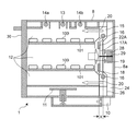
図14は、従来の加熱装置の構成を示す側面断面図である。図14に示されているように、従来の加熱装置41は、筐体48の前面にドア60が設けられており、加熱室47の前面開口がドア60により開閉されて、加熱室47に対して、食品である被加熱物100の出し入れを行うよう構成されている。加熱室47の後方(背面側)には、加熱室47に隣接して熱源室42が設けられている。熱源室42の内部には、循環ファン43と、この循環ファン43の中心軸と同じ中心を有する円環形状の熱源である電熱ヒータ45が設置されている。電熱ヒータ45は、循環ファン43の外周を取り囲むように配置されており、電熱ヒータ45の幅(奥行き方向の長さ)で規定される領域内に循環ファン43の羽根部44の幅が収まるように設定されている。
FIG. 14 is a side sectional view showing a configuration of a conventional heating device. As shown in FIG. 14, the
熱源室42のさらに後方(背面側)の空間には、モータ46が設置されている。そのモータ46のシャフト50は、熱源室42の背面壁42aを貫通しており、シャフト50の先端に循環ファン43が取り付けられている。すなわち、熱源室42の背面壁42aと筐体48の背面壁48aとの間の空間内に、モータ46が配置されている。
A
図14に示すように、加熱室47と熱源室42との間には平板な仕切り板49が設けられている。仕切り板49において、循環ファン43に対向する位置(中央領域)には吸気孔51が形成されており、筐体48に近い外周領域には吹き出し孔52が形成されている。
As shown in FIG. 14, a
このように構成された従来の加熱装置において、オーブン調理の際には、加熱室47内の被加熱物100である食品をムラなく調理するため、電熱ヒータ45の発熱とともに循環ファン43が稼働する。
In the conventional heating apparatus configured as described above, when the oven is cooked, the circulating
オーブン調理において、循環ファン43の羽根部44が回転することにより、加熱室47内の空気は、仕切り板49の吸気孔51から熱源室42に吸い込まれて、循環ファン43の遠心方向である外周方向へ送られる。循環ファン43により外周方向へ移動した空気は、循環ファン43の外側に配置された電熱ヒータ45により加熱される。電熱ヒータ45により加熱された空気は、仕切り板49の外周領域に設けられた吹き出し孔52を通り加熱室47内に送り込まれる。
In the oven cooking, when the
加熱室47内に送り込まれた熱風は、加熱室47の内部において循環して、加熱室47内の雰囲気温度を均一に上昇させる。このため、加熱室47内の被加熱物である食品をムラなくオーブン調理することができる。このような従来技術としては、例えば、日本の特開2008−14619号公報に開示された加熱装置がある。
The hot air sent into the
図15及び図16は、それぞれ、特開2008−14619号公報に開示された従来の加熱装置41における循環ファン43を示している。図15は、従来の加熱装置41における循環ファン43と電熱ヒータ45を示す正面図である。図16は、循環ファン43の羽根部44の先端部分を示す斜視図である。図16に示されているように、循環ファン43の羽根部44は、回転方向を含む面と平行な面を持つ底面板44aと、この底面板44aに対してほぼ垂直に設けられた羽根板44bで構成されている。
15 and 16 show a
上記のように構成された従来の加熱装置において、循環ファン43により十分な風量を発生させるためには、羽根板44bの幅、すなわち、回転軸方向(奥行き方向)の寸法(図16において符号Wで示す長さ)を、例えば12mmから19mm程度に広くし、且つ循環ファン43の回転速度を速く設定していた。このように設定された加熱装置においては、駆動トルクの大きなモータ46を用いる必要があった。このように、従来の加熱装置においては、加熱室47の背後に形成する熱源室42には大きな羽根板44bを有する循環ファン43を配置し、さらに熱源室42の背後の空間には大きな駆動トルクを有するモータ46を配置しているため、装置が大型化し、特に奥行き方向の寸法が大きくなってしまうという問題があった。奥行き方向の寸法が大きな加熱装置の場合には、設置スペースとして大きな領域を確保する必要があり、例えば、当該加熱装置41を食器棚に載置することができない場合があった。
In the conventional heating apparatus configured as described above, in order to generate a sufficient amount of air by the
本発明は、上記の従来の加熱装置における課題を解決するものであり、加熱室としての必要な容積を確保しつつ、加熱装置の奥行き方向の寸法を小さくし、効率高く加熱することができる加熱装置の提供を目的とする。 The present invention solves the above-described problems in the conventional heating apparatus, and while ensuring the necessary volume as a heating chamber, the heating apparatus can be heated with high efficiency by reducing the dimension in the depth direction of the heating apparatus. The purpose is to provide a device.
なお、以下の説明において、羽根部の幅(W)に依存する回転軸方向(奥行き方向)の循環ファンの寸法を、循環ファンの厚さと称す。すなわち、羽根部の幅(W)が大きくなると循環ファンは厚くなり、羽根部の幅(W)が小さくなると循環ファンは薄くなる。 In the following description, the dimension of the circulation fan in the rotation axis direction (depth direction) depending on the blade width (W) is referred to as the thickness of the circulation fan. That is, when the blade width (W) increases, the circulation fan becomes thicker, and when the blade width (W) decreases, the circulation fan becomes thinner.
本発明に係る第1の観点の加熱装置は、被加熱物を収容する加熱室と、
前記加熱室に隣接し、前記加熱室内に熱風を供給する熱源室と、
吸気孔と吹き出し孔とを有し、前記加熱室と前記熱源室を仕切る仕切り板と、を備えた加熱装置であって、
前記熱源室には、モータの回転軸に取り付けられた循環ファンと、前記循環ファンにより移動した空気を加熱する熱源と、が設けられ、
前記循環ファンが、主板と、前記主板に設けられた複数の羽根部を有し、
前記羽根部のそれぞれが、前記主板の平面に対して直角な複数の翼片で構成され、前記複数の翼片において、入口角を構成する前記循環ファンの回転中心軸(後述の実施の形態1における中心Pに相当)に最も近い翼片(後述の実施の形態1における第2の翼片21bに相当)の面と、出口角を構成する前記循環ファンの回転中心軸から最も遠い翼片(後述の実施の形態1における第1の翼片21aに相当)の面が異なる面で構成されている。このように構成された第1の観点の加熱装置は、循環ファンの仕事率が向上し、小さな駆動トルクで回転を開始し、高い効率で熱源へ空気を送ることができる。このため、第1の観点の加熱装置は、加熱室内の温度を所定温度まで上昇させる時間を短縮することができ、結果として加熱時間の短縮を図ることが可能となる。A heating device according to a first aspect of the present invention includes a heating chamber that houses an object to be heated,
A heat source chamber adjacent to the heating chamber and supplying hot air into the heating chamber;
A heating device having an intake hole and a blowout hole, and comprising a partition plate that partitions the heating chamber and the heat source chamber;
The heat source chamber is provided with a circulation fan attached to a rotating shaft of a motor, and a heat source for heating the air moved by the circulation fan,
The circulation fan has a main plate and a plurality of blade portions provided on the main plate,
Each of the blade portions is composed of a plurality of blade pieces perpendicular to the plane of the main plate, and the rotation axis of the circulation fan constituting the inlet angle in the plurality of blade pieces (
本発明に係る第2の観点の加熱装置は、前記の第1の観点の構成において、入口角が、前記循環ファンの回転中心軸に最も近い翼片の面と前記主板の面とが交わる第1の交線(後述の実施の形態1における折れ曲げ線Fに相当)における前記循環ファンの回転中心軸に最も近い点と回転中心点とを結ぶ直線と、前記第1の交線とのなす角度であり、
出口角OAが、前記循環ファンの回転中心軸から最も遠い翼片の面と前記主板の面とが交わる第2の交線(後述の実施の形態1における折れ曲げ線Eに相当)における前記循環ファンの回転中心軸から最も遠い点での回転方向の接線と、前記第2の交線とのなす角度であり、
前記入口角が、50度から60度の範囲内に設定されており、前記出口角が、40度から50度の範囲内に設定されている。このように構成された第2の観点の加熱装置は、従来のものより薄い循環ファンと、駆動トルクの小さいモータの使用が可能となり、循環ファンの良好な立ち上がり性能と省電力性能とを実現しつつ装置全体の小型化を図ることが可能となる。According to a second aspect of the present invention, there is provided a heating apparatus according to the first aspect, wherein the blade angle closest to the rotation center axis of the circulation fan and the surface of the main plate intersect at the inlet angle. A straight line connecting a point closest to the rotation center axis of the circulation fan and a rotation center point at one intersection line (corresponding to a bending line F in the first embodiment to be described later) and the first intersection line. Angle,
The exit angle OA is the circulation at a second intersection line (corresponding to a fold line E in the first embodiment described later) where the surface of the blade piece farthest from the rotation center axis of the circulation fan and the surface of the main plate intersect. An angle formed by a tangent to the rotation direction at a point farthest from the rotation center axis of the fan and the second intersection line;
The entrance angle is set in a range of 50 degrees to 60 degrees, and the exit angle is set in a range of 40 degrees to 50 degrees. The heating device of the second aspect configured as described above can use a circulation fan thinner than the conventional one and a motor having a small driving torque, and realizes a good start-up performance and power saving performance of the circulation fan. However, it is possible to reduce the size of the entire apparatus.
本発明に係る第3の観点の加熱装置は、前記の第1の観点の構成において、前記循環ファンにおける各羽根部の複数の翼片が、切り出された主板材の一部を直角に折り曲げて形成され、各翼片が前記主板材の一部を別々に折り曲げて形成されている。このように構成された第3の観点の加熱装置は、プレス加工を用いて一枚の板材から循環ファンを形成することができるため、循環ファンのコストダウンを図ることができる。 According to a third aspect of the present invention, there is provided a heating apparatus according to the first aspect, wherein a plurality of blade pieces of each blade portion of the circulation fan bend a part of the cut main plate material at a right angle. Each wing piece is formed by separately bending a part of the main plate. Since the heating device of the 3rd viewpoint comprised in this way can form a circulation fan from one board | plate material using press work, it can aim at the cost reduction of a circulation fan.
本発明に係る第4の観点の加熱装置は、前記の第1の観点の構成において、前記循環ファンにおける各羽根部の複数の翼片が、切り出された主板材の一部を折り曲げて形成され、各羽根部の複数の翼片が1枚の板材を折り曲げて形成されている。このように構成された第4の観点の加熱装置は、プレス加工を用いて一枚の板材から循環ファンを形成することができるため、循環ファンのコストダウンを図ることができる。 According to a fourth aspect of the present invention, in the heating apparatus according to the first aspect, the plurality of blade pieces of each blade portion of the circulation fan are formed by bending a part of the cut main plate material. A plurality of blade pieces of each blade portion are formed by bending one plate material. Since the heating device of the 4th viewpoint comprised in this way can form a circulation fan from one board | plate material using press work, it can aim at the cost reduction of a circulation fan.
本発明に係る第5の観点の加熱装置は、前記の第3または第4の観点の構成において、前記循環ファンが、前記主板の一部を折り曲げることにより生じる切欠きを塞ぐ補完板と、前記主板とともに前記複数の翼片を挟持する副板とを有するよう構成してもよい。このように構成された第5の観点の加熱装置は、従来のものより薄い循環ファンと、駆動トルクの小さいモータの使用が可能となり、循環ファンの良好な立ち上がり性能と省電力性能とを実現しつつ装置全体の小型化を図ることが可能となる。 A heating device according to a fifth aspect of the present invention is the heating plate according to the third or fourth aspect, wherein the circulation fan closes a notch generated by bending a part of the main plate; You may comprise so that it may have a subplate which clamps the said several blade piece with a main plate. The heating device according to the fifth aspect configured as described above enables the use of a circulation fan thinner than the conventional one and a motor having a small driving torque, and realizes good start-up performance and power saving performance of the circulation fan. However, it is possible to reduce the size of the entire apparatus.
本発明に係る第6の観点の加熱装置は、前記の第1の観点の構成において、前記循環ファンにおける前記翼片の一部が、前記主板から遠心方向に突出するよう構成してもよい。このように構成された第6の観点の加熱装置は、主板の後方(背面側)に向かう風量を増やすことができる。 The heating device according to a sixth aspect of the present invention may be configured such that a part of the blade piece in the circulation fan protrudes from the main plate in the centrifugal direction in the configuration of the first aspect. The 6th viewpoint heating apparatus comprised in this way can increase the airflow which goes to the back (back side) of a main board.
本発明に係る第7の観点の加熱装置は、前記の第1の観点の構成において、前記循環ファンにおける前記翼片の一部が、前記主板から遠心方向に突出するよう構成されており、前記熱源が、前記循環ファンの翼片より外側の位置であり、かつ、前記循環ファンよりも後方側にずれた位置に設けてもよい。このように構成された第7の観点の加熱装置は、主板の後方(背面側)に向かう風量を増やすことができ、熱源へ効率の高い送風が可能となる。 A heating device of a seventh aspect according to the present invention is configured such that, in the configuration of the first aspect, a part of the blade piece in the circulation fan protrudes in a centrifugal direction from the main plate, The heat source may be provided at a position outside the blades of the circulation fan and at a position shifted rearward from the circulation fan. The heating device according to the seventh aspect configured as described above can increase the amount of air flowing toward the rear (back side) of the main plate, and can efficiently blow air to the heat source.
本発明に係る第8の観点の加熱装置は、前記の第1の観点の構成において、前記循環ファンにおける前記翼片の入口角が、55度に設定されており、前記循環ファンにおける前記翼片の出口角が、45度に設定してもよい。このように構成された第8の観点の加熱装置は、従来のものより薄い循環ファンと、駆動トルクの小さいモータの使用が可能となり、循環ファンの良好な立ち上がり性能と省電力性能とを実現しつつ装置全体の小型化を図ることが可能となる。 According to an eighth aspect of the present invention, there is provided a heating apparatus according to the first aspect, wherein an inlet angle of the blade piece in the circulation fan is set to 55 degrees, and the blade piece in the circulation fan is set. The exit angle may be set to 45 degrees. The heating device according to the eighth aspect configured as described above enables the use of a circulation fan thinner than the conventional one and a motor having a small driving torque, and realizes good start-up performance and power saving performance of the circulation fan. However, it is possible to reduce the size of the entire apparatus.
本発明に係る第9の観点の加熱装置において、前記の第1の観点の前記循環ファンにおける前記翼片は、前記モータの回転軸の軸方向の幅(W)が、6mmから15mmの範囲内に設定してもよい。このように構成された第9の観点の加熱装置は、従来のものより薄い循環ファンと、駆動トルクの小さいモータの使用が可能となり、循環ファンの良好な立ち上がり性能と省電力性能とを実現しつつ装置全体の小型化を図ることが可能となる。 In the heating device according to the ninth aspect of the present invention, the blade piece of the circulation fan according to the first aspect has an axial width (W) of the rotating shaft of the motor in the range of 6 mm to 15 mm. May be set. The heating device of the ninth aspect configured as described above can use a circulation fan thinner than the conventional one and a motor having a small driving torque, and realizes a good start-up performance and power saving performance of the circulation fan. However, it is possible to reduce the size of the entire apparatus.
本発明に係る第10の観点の加熱装置において、前記の第1の観点の前記循環ファンは、6枚から16枚の羽根部を有するよう構成してもよい。このように構成された第10の観点の加熱装置は、従来のものより薄い循環ファンと、駆動トルクの小さいモータの使用が可能となり、循環ファンの良好な立ち上がり性能と省電力性能とを実現しつつ装置全体の小型化を図ることが可能となる。 In the heating device according to the tenth aspect of the present invention, the circulation fan according to the first aspect may be configured to have 6 to 16 blade portions. The heating device according to the tenth aspect configured as described above enables the use of a circulation fan thinner than the conventional one and a motor having a small driving torque, and realizes good start-up performance and power saving performance of the circulation fan. However, it is possible to reduce the size of the entire apparatus.
本発明に係る第11の観点の加熱装置は、前記の第1の観点の構成において、前記循環ファンの回転中心軸に最も近い翼片の面と前記主板の面とが交わる第1の交線の長さ(後述の実施の形態1における長さDに相当)が、前記循環ファンの回転中心軸から最も遠い翼片の面と前記主板の面とが交わる第2の交線の長さ(後述の実施の形態1における長さCに相当)の2.5倍から3.0倍の範囲内に設定してもよい。このように構成された第11の観点の加熱装置は、従来のものより薄い循環ファンと、駆動トルクの小さいモータの使用が可能となり、循環ファンの良好な立ち上がり性能と省電力性能とを実現しつつ装置全体の小型化を図ることが可能となる。
A heating device according to an eleventh aspect of the present invention is the first aspect of the configuration according to the first aspect, wherein the surface of the blade piece closest to the rotation center axis of the circulation fan intersects the surface of the main plate. (Corresponding to a length D in the first embodiment to be described later) is a length of a second intersection line (a surface of the main plate and the surface of the blade piece furthest from the rotation central axis of the circulation fan) ( It may be set in the range of 2.5 to 3.0 times the length C in
本発明に係る第12の観点の加熱装置は、前記の第1の観点の構成において、前記循環ファンの回転中心軸から最も遠い翼片の面と前記主板の面とが交わる第2の交線における前記回転中心軸から最も遠い点から前記回転中心軸までの距離(後述の実施の形態1における距離A/2に相当)に対する、前記循環ファンの回転中心軸に最も近い翼片の面と前記主板の面とが交わる第1の交線における前記回転中心軸から最も近い点から前記回転中心軸までの距離(後述の実施の形態1における距離B/2に相当)の比が0.5から0.7の範囲内に設定してもよい。このように構成された第12の観点の加熱装置は、従来のものより薄い循環ファンと、駆動トルクの小さいモータの使用が可能となり、循環ファンの良好な立ち上がり性能と省電力性能とを実現しつつ装置全体の小型化を図ることが可能となる。
A heating device according to a twelfth aspect of the present invention is the second intersection line in which the surface of the blade piece farthest from the rotation center axis of the circulation fan and the surface of the main plate intersect in the configuration of the first aspect. The surface of the blade piece closest to the rotation center axis of the circulation fan with respect to the distance from the point farthest from the rotation center axis to the rotation center axis (corresponding to the distance A / 2 in the first embodiment described later) The ratio of the distance (corresponding to the distance B / 2 in
本発明に係る第13の観点の加熱装置は、前記の第1の観点の構成において、前記循環ファンにおける各羽根部の翼片が、入口角を構成する翼片と出口角を構成する翼片の2枚で構成され、前記2枚の翼片の境界部分の曲率半径が20mmから30mmの範囲内に設定してもよい。このように構成された第13の観点の加熱装置は、従来のものより薄い循環ファンと、駆動トルクの小さいモータの使用が可能となり、循環ファンの良好な立ち上がり性能と省電力性能とを実現しつつ装置全体の小型化を図ることが可能となる。 A heating apparatus according to a thirteenth aspect of the present invention is the structure according to the first aspect, wherein the blade pieces of each blade section in the circulation fan are blade pieces that form an inlet angle and blade pieces that form an outlet angle. The radius of curvature of the boundary portion between the two blade pieces may be set within a range of 20 mm to 30 mm. The heating device according to the thirteenth aspect configured as described above enables the use of a circulation fan thinner than the conventional one and a motor having a small driving torque, and realizes good start-up performance and power saving performance of the circulation fan. However, it is possible to reduce the size of the entire apparatus.
本発明の加熱装置は、加熱室としての必要な容積を確保しつつ、加熱装置の奥行き方向の寸法を小さくし、効率高く加熱することができる。 The heating device according to the present invention can heat efficiently while reducing the dimension in the depth direction of the heating device while securing a necessary volume as a heating chamber.
以下、本発明の加熱装置に係る実施の形態としてオーブン電子レンジについて、添付の図面を参照しながら説明する。なお、本発明の加熱装置は、以下の実施の形態に記載したオーブン電子レンジの構成に限定されるものではなく、以下の実施の形態において説明する技術的思想と同等の技術的思想及び当技術分野における技術常識に基づいて構成される加熱装置を含むものである。 Hereinafter, an oven microwave oven according to an embodiment of the heating device of the present invention will be described with reference to the accompanying drawings. Note that the heating device of the present invention is not limited to the configuration of the oven microwave oven described in the following embodiment, but the technical idea equivalent to the technical idea described in the following embodiment and the present technology. It includes a heating device configured based on common technical knowledge in the field.
(実施の形態1)
図1から図3は、本発明に係る実施の形態1の加熱装置としてのオーブン電子レンジの構成を示すものである。図1は実施の形態1の加熱装置における概略内部構成を示す側面断面図である。図2は実施の形態1の加熱装置における被加熱物を配置する加熱室と、熱源となるシーズヒータを収納する熱源室とを仕切る仕切り板を示す正面図である。図3は熱源室内に設けられた循環ファンの羽根部の構成を示している。(Embodiment 1)
1 to 3 show a configuration of an oven microwave oven as a heating device according to
以下、本発明に係る実施の形態1の加熱装置としてのオーブン電子レンジについて詳細に説明する。
図1に示されているように、実施の形態1の加熱装置1は、筐体8の内部に食品である被加熱物100を収納するための略直方体構造を持つ加熱室12が形成されている。加熱室12は、金属材料により天井面、底面、左側面、右側面及び背面を構成する壁板と、被加熱物100を出し入れするために開閉するドア30と、被加熱物100を載置するための載置台101とにより構成されている。実施の形態1の加熱装置1においては、載置台101が上下2段に配置され得るよう構成されている。Hereinafter, the oven microwave oven as the heating device according to the first embodiment of the present invention will be described in detail.
As shown in FIG. 1, the
加熱室12の下方には、マグネトロン10とアンテナ11が設置されており、マグネトロン10において発生した電磁波が、アンテナ11を経由して加熱室12内に放射され得るよう構成されている。このように構成された加熱室12は、ドア30を閉じることにより、加熱室12内に供給された電磁波が加熱室12内部に閉じ込められる構成である。
Below the
また、実施の形態1の加熱装置1においては、加熱室12内の上部の天井面には、棒状のグリル用ヒータとして、近赤外線を発生する1本のアルゴンランプヒータ13と、遠赤外線を発生する2本のミラクロンヒータ14a,14bが設けられている。
Moreover, in the
さらに、実施の形態1の加熱装置1においては、加熱室12の後方である背面側には、加熱室12に隣接して熱源室15が設けられている。熱源室15の内部には、遠心ファンである循環ファン17Aと、この循環ファン17Aの回転動作により送られた空気を加熱するシーズヒータ16が設置されている。実施の形態1の加熱装置1におけるシーズヒータ16は、循環ファン17Aの羽根部22Aの外側に配置され、且つ背面側にオフセットした位置に設けられており、略正方形の枠形状を有している。なお、実施の形態1においては、シーズヒータ16が略正方形の枠形状を有した例で説明するが、本発明はこのような構成に限定されるものではなく、他の形状、例えば円環の枠形状でもよい。
Furthermore, in the
熱源室15のさらに後方(背面側)の空間である駆動室24には、駆動源であるモータ28が設置されている。このモータ28のシャフト29は、熱源室15の背面を構成する熱源室背面壁26を貫通しており、そのシャフト29の先端には循環ファン17Aが取り付けられている。このように、熱源であるシーズヒータ16が設置された熱源室15と、駆動源であるモータ28が設置された駆動室24は、熱源室背面壁26により仕切られ、断熱されている。
A
また、加熱室12と熱源室15との間には仕切り板18が設けられており、この仕切り板18により加熱室12と熱源室15との間が空間的に仕切られている。
仕切り板18において、循環ファン17Aの中心近傍に対向する位置(中央領域)には吸気孔19が形成されており、筐体8に近い領域である、循環ファン17Aの外周領域の複数箇所には吹き出し孔20が形成されている。A
In the
実施の形態1の加熱装置1において、図1に示すように、仕切り板18及び熱源室背面壁26は、平板形状ではなく、それぞれの外周部分である筐体8に近い領域がモータ28を設けた駆動室24側に入り込むよう凹形状に形成されている。言い換えると、熱源室背面壁26は、モータ28に対向する中央部分が加熱室側へ突出するように、その中央領域に凸部が形成されている。その凸部で形成された空間内にモータ28の一部が入り込むよう構成されている。また、仕切り板18においては、熱源室背面壁26と同様に、その中央領域に凸部が形成されている。すなわち、仕切り板18と熱源室背面壁26は同様の断面形状を有しており、仕切り板18と熱源室背面壁26との間隔(奥行き方向の長さ)は、中央領域と外周領域のそれぞれにおいて略同じ距離となっている。
In the
また、実施の形態1の加熱装置1においては、後述するように循環ファン17Aの羽根部22Aの幅(加熱装置1における奥行き方向の長さ)が小さく形成されている。このため、熱源室15の奥行き方向の長さも短く構成されている。すなわち、仕切り板18及び熱源室背面壁26との奥行き方向の間隔が狭く構成されており、熱源室15は、被加熱物100を収納する加熱室12に比べて非常に小さい空間となっている。
Moreover, in the
次に、実施の形態1の加熱装置1の構成における、シーズヒータ16の設置位置について説明する。
図1に示されるように、シーズヒータ16は、従来の設置位置よりも後方、すなわち、モータ28側に寄ったオフセットされた位置に配置されている。言い換えると、枠状であるシーズヒータ16における熱線(発熱部分の中心を結ぶ枠状の線)を含む平面(熱線面)が、循環ファン17Aの各羽根部22Aにおける力点の回転面(力点面)より後方となるよう配置されている。すなわち、図1に示すように、シーズヒータ16の前記熱線面は、循環ファン17Aの前記力点面より背面側に距離Xだけオフセットした位置となっている。ここで、各羽根部22Aにおける力点とは、循環ファン17Aの回転時において、各羽根部22Aのブレード表面に加わる力の仮想点である。Next, the installation position of the sheathed
As shown in FIG. 1, the sheathed
図2は加熱室12と熱源室15とを仕切る仕切り板18を示す正面図である。図2に示されるように、仕切り板18の中央領域には、加熱室12側から熱源室15側へ空気を吸入するための複数の吸気孔19が形成されている。また、仕切り板18の外周領域には、熱源室15側から加熱室12側への熱風の吹き出しを行うための複数の吹き出し孔20が形成されている。図2に示すように、複数の吹き出し孔20が形成された吹き出し領域は、仕切り板18の複数の部分に形成されており、当該加熱装置1の仕様に応じてその吹き出し領域の形成位置が設定されている。吸気孔19及び吹き出し孔20は、多数のパンチ孔で形成されている。
FIG. 2 is a front view showing a
図3は循環ファン17Aの羽根部22Aのブレード構成を示している。図3の(a)は循環ファン17Aの正面図であり、図3の(b)は循環ファン17Aの側面図である。
図3に示されるように、循環ファン17Aは、モータ28のシャフト29の先端部分に取り付けられる平板な主板33Aと、この主板33Aに設けられた8枚の羽根部22Aと、を有している。主板33Aの中心点(重心点)Pにはモータ28のシャフト29の先端部分が固着されている。FIG. 3 shows a blade configuration of the
As shown in FIG. 3, the circulation fan 17 </ b> A has a flat main plate 33 </ b> A that is attached to the tip end portion of the
各羽根部22Aは、円板状の所定形状に切り出された主板33Aに、所定の切り込みを入れて形成された2つの第1の翼片21aと第2の翼片21bで構成されている。第1の翼片21aと第2の翼片21bは、主板33Aの平面に対して略垂直方向に折り曲げることで形成される。すなわち、循環ファン17Aは、切り出された主板33Aに対して2箇所の位置において折り曲げることにより、第1の翼片21a及び第2の翼片21bが形成される。図3において、符号Eにて示す線に沿って折り曲げることにより第1の翼片21aが形成され、そして符号Fにて示す線に沿って折り曲げることにより第2の翼片21bが形成される。図4は、羽根部22Aである第1の翼片21a及び第2の翼片21bが形成される前の主板33Aの状態を示す平面図であり、循環ファン17Aを形成するために切り出された金属板を示している。図4において、破線部分が折り曲げ箇所(E,F)である。
Each
上記のように構成された循環ファン17Aが回転することにより、羽根部22Aにより熱源室15内の空気が遠心方向に流される。このため、加熱室12内の空気は仕切り板18に形成された吸気孔19を通り、熱源室15内に吸い込まれる。熱源室15内においては、循環ファン17Aの回転動作により遠心方向に流され移動した空気が、熱源室15の内壁に沿ってシーズヒータ16に向かって移動し加熱される。シーズヒータ16により加熱された熱風は、仕切り板18の外周領域に形成された吹き出し孔20を通り加熱室12内に送り込まれる。
By rotating the
このように加熱室12内に送り込まれた熱風は、加熱室12の内部を循環することにより、加熱室12内の雰囲気温度を均一に短時間で上昇させることができる。このように、実施の形態1の加熱装置1においては、特殊形状の循環ファン17Aを用いて、その外周で背面側のオフセットされた位置に配設されたシーズヒータ16により所望温度の熱風が形成される。その熱風が加熱室12内部を循環することにより、良好なオーブン調理が省電力性能の小型化された装置で実現することができる。
Thus, the hot air sent into the
以下、実施の形態1の加熱装置1における羽根部22Aの具体的な形状について説明する。なお、以下に説明する具体的な数値は、一例であり、本発明の加熱装置における羽根部の形状を特定するものではない。
Hereinafter, a specific shape of the
図3に示す循環ファン17Aにおいて、第2の翼片21bの折り曲げ線Fにおける中心Pに最も近い点と中心Pとを結んだ直線と、第2の翼片21bの折り曲げ線Fとのなす角度が、翼入口角であり、この角度を入口角IAとする。また、第1の翼片21aの折り曲げ線Eにおける中心から最も遠い点である、主板33Aの外周との交点における接線と、第1の翼片21aの折り曲げ線Eとのなす角度が、翼出口角であり、この角度を出口角OAとする。実施の形態1の加熱装置1においては、入口角IAが55度であり、出口角が45度に設定されている。
In the
また、循環ファン17Aにおいては、8個の羽根部22Aが主板33Aにおいて中心Pに対して同じ角度間隔で形成されており、各羽根部22Aが主板33Aの中心Pに対して対象に形成されている。したがって、主板33Aにおける羽根部22Aは中心Pに関して向かい合うように形成されている。ここで、向かい合う2つの羽根部22A,22Aの第1の翼片21a,21aにおいて、中心Pから最も遠い端部同士の距離、すなわち主板33Aの外径をAとする。そして、向かい合う2つの羽根部22A,22Aの第2の翼片21bにおいて、中心Pに最も近い端部同士の距離(内径)をBとする。実施の形態1の加熱装置1における循環ファン17Aにおいて、外径(A)に対する内径(B)の比率である内外径比(B/A)を略0.6に設定している。この内外径比(B/A)としては、0.5から0.7の間が好ましい。なお、上記の内外径比(B/A)は主板33Aにおける直径である外径Aと内径Bとの比で表したが、第2の翼片21bの折り曲げ線Fの中心Pに最も近い点から中心までの距離(B/2)と、半径(A/2)とを用いてもよい。
Further, in the
第1の翼片21aの折り曲げ線Eの長さをCとし、第2の翼片21bの折り曲げ線Fの長さをDとすると、その比(C/D)、すなわち、第1の翼片21aと第2の翼片21bの長さの比(C/D)は、実施の形態1の加熱装置における循環ファン17Aにおいては、1/2.8である。実験によれば、第2の翼片21bの折り曲げ線Fの長さ(D)は、第1の翼片21aの折り曲げ線Eの長さ(C)の2.5倍から3.0倍の範囲内であれば好ましい結果が得られた。
When the length of the fold line E of the
なお、第1の翼片21a及び第2の翼片21bの各幅W(奥行き方向の長さ、図3の(b)参照)は、8mmに設定されており、この幅Wは6mmから15mmの間の長さが好ましい長さであった。
Each width W of the
なお、主板33Aに形成された第1の翼片21aと第2の翼片21bとの間は、隙間無く接触しており、曲面にて連続するよう形成することが好ましく、例えば、R25となるよう形成する。この曲率半径の好ましい範囲としては、20mmから30mmである。
The
図5は、回転数を無次元化した圧力損失特性(無次元PQ特性)を示すグラフであり、縦軸が静圧力係数を示し、横軸が流量係数を示している。図5においては、本発明に係る実施の形態1の加熱装置における循環ファン17Aを用いた場合の圧力損失特性(実線)と、後述する比較例としての循環ファンを用いた場合の圧力損失特性(破線)と、を比較したグラフである。すなわち、図5に示す圧力損失特性は、実施の形態1の循環ファン17Aと比較例としての循環ファンを用いて、風量を変化させた場合の風量(横軸)と静圧(縦軸)との関係を示している。
FIG. 5 is a graph showing a pressure loss characteristic (dimensionalless PQ characteristic) in which the rotational speed is made dimensionless. The vertical axis indicates the static pressure coefficient, and the horizontal axis indicates the flow coefficient. In FIG. 5, the pressure loss characteristic (solid line) when using the
図6は比較例としての循環ファン170におけるブレード構成及び環状の電熱ヒータ45を示している。図6の(a)は循環ファン170の正面図であり、図6の(b)は循環ファン170の側面図である。
FIG. 6 shows a blade configuration and an annular
図6に示されるように、比較例としての循環ファン170は、モータのシャフトの先端部分に取り付けられる平板な主板330に8枚の羽根部210が形成されている。この羽根部210は、主板330に対して直線状の1箇所の折り曲げ部における折り曲げ加工により形成されている。したがって、羽根部210は1枚の平板な翼片により構成されている。この翼片の幅W(加熱装置における奥行き方向の長さ)は、約20mmである。また、循環ファン170の主板330の外形寸法は、実施の形態1における循環ファン17Aの主板33Aの外径寸法(A)と同じである。電熱ヒータ45は、循環ファン170の外周を取り囲むように配置されており、電熱ヒータ45の幅(奥行き方向の長さ)で規定される領域内に循環ファン170の羽根部210の幅が収まるように設定されている。
As shown in FIG. 6, a
上記のように構成された比較例としての循環ファン170は、前述の背景技術において説明した従来例の循環ファン43と同様に、実施の形態1における循環ファン17Aの羽根部22Aより大きな羽根部210を有している。このように構成された比較例と、実施の形態1の加熱装置における循環ファン17Aとの圧力損失特性を比較すると、図6に示されるように、循環ファン17Aは、比較例の循環ファン170より風量特性が大きく向上していることが理解できる。
The
実施の形態1の加熱装置における循環ファン17Aにおいては、比較例の循環ファン170と比較して、羽根部22Aの形状の幅(W)を小さくして、すなわち、羽根部22Aを薄くして、羽根部22Aのブレード面を狭くしても、風量特性が向上している。したがって、実施の形態1の加熱装置においては、循環ファン17Aを駆動するために駆動トルクの小さなモータを使用しても、循環ファンの良好な立ち上がり性能と省電力性能とを実現できるとともに、装置全体の小型化、特に奥行き寸法を短くすることができる。その結果、実施の形態1の加熱装置を、例えば、食器棚上に配置しても、加熱装置のドア等が食器棚から飛び出して、使用者にとって邪魔になることがなく、食器棚上に確実に配置できる外観寸法となる。
In the
実施の形態1の加熱装置における循環ファン17Aにおいては、複数の羽根部22Aが一枚の金属板に対する単純な折り曲げ加工により形成される構成である。このため、実施の形態1における循環ファン17Aは、特殊形状を有する構造であるにもかかわらず、製造コストを増加させる必要がなく、高機能の装置の低価格化を図ることが可能となる。
The
以上のように、実施の形態1の加熱装置においては、循環ファン17Aにおける入口角IAを55度に設定し、出口角OAを45度に設定した例で説明したが、入口角IAを50度に設定し、出口角OAを40度に設定することにより、循環ファン17Aの風量をより多くすることができる。また、入口角IAを60度に設定し、出口角OAを50度に設定すると、循環ファンの圧力を高くすることができ、圧力損失の大きな送風経路でも使用可能となる。このように、本発明の加熱装置においては、加熱装置の仕様などに応じて、循環ファンにおける入口角IAと出口角OAを所望の角度に設定し、高機能及び省エネルギー化を図ることができる。
As described above, in the heating device according to the first embodiment, the example in which the inlet angle IA in the
また、実施の形態1の加熱装置においては、循環ファン17Aの羽根部22Aの枚数を8枚としたが、本発明の加熱装置においては、6枚から16枚程度までの羽根部を有する循環ファンであっても、実施の形態1における羽根部22Aと同様な構成とすることにより同様の効果を得ることができる。したがって、本発明は、実施の形態1の加熱装置として説明した羽根部の枚数に限定されるものではない。
Further, in the heating device of the first embodiment, the number of the
(実施の形態2)
以下、本発明に係る実施の形態2の加熱装置について説明する。図7は、本発明に係る実施の形態2の加熱装置に搭載される循環ファン17Bのブレード構成を示す平面図である。図8は、循環ファン17Bにおける羽根部22Bが形成される前の主板33Bの状態を示す平面図であり、循環ファン17Bを形成するために切り出された金属板を示している。図8において、破線部分が折り曲げ箇所である。なお、実施の形態2の加熱装置において、前述の実施の形態1の加熱装置と同じ機能、構成を有するものについては同じ符号を付与し、その説明を省略する。(Embodiment 2)
Hereinafter, the heating apparatus of Embodiment 2 which concerns on this invention is demonstrated. FIG. 7 is a plan view showing a blade configuration of
図7に示されるように、実施の形態2の加熱装置において、前述の実施の形態1の加熱装置の構成と異なる点は、循環ファン17Bの羽根部22Bが一枚の翼片により第1の翼片21a及び第2の翼片21bが形成されている点である。
As shown in FIG. 7, the heating device of the second embodiment is different from the configuration of the heating device of the first embodiment described above in that the
すなわち、実施の形態2の加熱装置においては、略円板状の所定形状に切り出された金属板(主板33B)に所定の切り込みを入れることにより、1つの翼片材が形成される。この翼片材を、主板33Bに対して垂直な方向に1度目の折り曲げ加工を行い、次に、折り曲げられた翼片材の所定位置において、主板33Bの平面に対して平行な方向に2度目の折り曲げ加工を行うことにより、羽根部22Bの第1の翼片21a及び第2の翼片21bが形成される。
That is, in the heating device of the second embodiment, one blade piece material is formed by making a predetermined cut into a metal plate (
図8において、折り曲げ線G(破線)が1度目の折り曲げ加工位置を示しており、この折り曲げ線Gにおいて主板33Bに対して垂直方向に折り曲げられる。また、折り曲げ線H(破線)が2度目の折り曲げ加工位置を示しており、折り曲げ線Gで曲げられた翼片に対してさらに折り曲げ線Hにおいて折り曲げられる。この折り曲げ線Hの屈曲部分Rは、曲面で構成され、例えば、曲率半径が25mm(R25)で形成される。
In FIG. 8, a fold line G (broken line) indicates the first fold position, and the fold line G is bent in a direction perpendicular to the
上記のように、実施の形態2の加熱装置においては、実施の形態1の加熱装置における循環ファン17Aと同じ入口角IA、出口角OA、及び屈曲部分R(曲率半径:R25)を有する循環ファン17Bを実施の形態1における循環ファン17Aと同様に2箇所の折り曲げ加工により形成することができる。
As described above, in the heating device of the second embodiment, the circulation fan having the same inlet angle IA, outlet angle OA, and bent portion R (curvature radius: R25) as the
実施の形態2の加熱装置において、実施の形態1の加熱装置と比較した有利な点としては、羽根部22Bが1つの翼片を折り曲げて形成されるため、実施の形態2における循環ファン17Bは、実施の形態1における循環ファン17Aより、入口角IAと出口角OAの交わる位置(屈曲部分R)において生じやすい流れの剥離現象を抑制することができる。
In the heating device according to the second embodiment, as an advantage compared with the heating device according to the first embodiment, since the
このため、実施の形態2の加熱装置によれば、実施の形態1の加熱装置の場合より、循環ファン17Bの送風効率の向上、及び羽根部22Bから発生する乱流騒音の低減を図ることができる。
For this reason, according to the heating device of the second embodiment, it is possible to improve the blowing efficiency of the
なお、実施の形態2の加熱装置では、循環ファン17Bの羽根部22Bを8枚の翼片で構成した例で説明したが、羽根部22Bの翼片としては6枚から16枚程度までであれば同様の効果を得ることができる。翼片の枚数が多いほど、1枚の翼片から発生する乱流騒音電力が小さくなり、循環ファン全体の騒音を小さくすることができる。
In the heating device of the second embodiment, the example in which the
また、実施の形態2の加熱装置における循環ファン17Bにおいては、実施の形態1の加熱装置と同様に、第1の翼片21aと第2の翼片21bとの屈曲部分Rの曲率半径を25mmとした例で説明したが、曲率半径を20mmから30mm程度までの範囲内に設定しても同様の効果を奏するものであり、また、屈曲部分Rをインボリュート曲線等で結んだ場合でも同様の効果を得ることができる。
Further, in the
(実施の形態3)
以下、本発明に係る実施の形態3の加熱装置について説明する。図9は、本発明に係る実施の形態3の加熱装置に搭載される循環ファン17Cの構成を示す図である。図9において、(a)は実施の形態3の加熱装置における循環ファン17Cの平面図であり、(b)は循環ファン17Cの側面図である。なお、実施の形態3の加熱装置において、前述の実施の形態1及び実施の形態2の加熱装置と同じ機能、構成を有するものについては同じ符号を付与し、その説明を省略する。(Embodiment 3)
Hereinafter, the heating apparatus of Embodiment 3 which concerns on this invention is demonstrated. FIG. 9 is a diagram showing a configuration of a
図9に示されるように、実施の形態3の加熱装置において、前述の実施の形態2の構成と異なる点は、翼片を折り曲げて羽根部22Cを形成したことにより、主板33Cに生じた切欠き34を補完する補完板35を設けたことと、羽根部22Cの翼片を主板33Cとともに挟持する副板(シュラウド)36を設けたことである。
As shown in FIG. 9, in the heating device of the third embodiment, the difference from the configuration of the second embodiment described above is that the
実施の形態3の加熱装置における循環ファン17Cは、実施の形態2の加熱装置における循環ファン17Bに補完板35と、副板(シュラウド)36を設けた構成である。補完板35は、循環ファン17Cにおける背面側に設けられており、熱源室15の熱源室背面壁に対向するように設けられている(図1参照)。補完板35は、主板33Cにある切欠き34を塞ぐように設けられており、循環ファン17Cの中央領域から吸入した空気を遠心方向へ効率高く移動させている。
The
一方、副板(シュラウド)36は、循環ファン17Cにおける正面側に設けられており、熱源室15の仕切り板18に対向するように設けられている(図1参照)。副板36は、羽根部22Cを覆うように設けられている。なお、副板36は、その中央領域が中空となった円環形状であり、中央領域から加熱室12内の空気を吸気する構成である。
On the other hand, the sub-plate (shroud) 36 is provided on the front side of the
上記のように構成された実施の形態3の加熱装置における循環ファン17Cにおいては、補完板35を設けることにより、主板33Cの切欠き34から下流側(背面側)へ漏れる空気を防止し、副板(シュラウド)36を設けることにより、羽根部22Cに吸入した空気を上流側(正面側)へ漏れることを防止することができる。このため、実施の形態3の加熱装置における循環ファン17Cは、送風効率が大幅に向上している。
In the
図10は、回転数を無次元化した圧力損失特性(無次元PQ特性)を示すグラフであり、縦軸が静圧力係数を示し、横軸が流量係数を示している。図10においては、実施の形態3の加熱装置における循環ファン17Cを用いた場合の圧力損失特性(実線)と、前述の図6で説明した比較例の圧力損失特性(破線)と、を比較したグラフである。すなわち、図10に示す圧力損失特性は、実施の形態3の循環ファン17Cと比較例としての循環ファンを用いて、風量を変化させた場合の風量(横軸)と静圧(縦軸)との関係を示している。
FIG. 10 is a graph showing the pressure loss characteristic (dimensionalless PQ characteristic) in which the rotational speed is made dimensionless. The vertical axis shows the static pressure coefficient, and the horizontal axis shows the flow coefficient. In FIG. 10, the pressure loss characteristic (solid line) when the
図10のグラフからも明らかなように、実施の形態3の加熱装置における循環ファン17Cは、比較例の循環ファンより風量特性が大幅に向上しており、特に圧力損失が大きい、流量が制限された状態における風量特性が向上している。
As is clear from the graph of FIG. 10, the
以上のように、実施の形態3の加熱装置においては、薄型ファンと小型モータとを用いて、循環ファンの良好な立ち上がり性能と省電力性能とを実現することができるとともに、装置全体の小型化を図ることが可能となる。 As described above, in the heating device according to the third embodiment, it is possible to achieve good start-up performance and power saving performance of the circulation fan by using a thin fan and a small motor, and to reduce the size of the entire device. Can be achieved.
(実施の形態4)
以下、本発明に係る実施の形態4の加熱装置について説明する。図11は、本発明に係る実施の形態4の加熱装置に搭載される循環ファン17Dの構成を示す平面図である。図12は、実施の形態4における循環ファン17Dの斜視図である。なお、実施の形態4の加熱装置において、前述の実施の形態1から実施の形態3と同じ機能、構成を有するものについては同じ符号を付与し、その説明を省略する。(Embodiment 4)
Hereinafter, the heating apparatus of Embodiment 4 which concerns on this invention is demonstrated. FIG. 11 is a plan view showing a configuration of a
図11及び図12に示されているように、実施の形態4の加熱装置において、前述の実施の形態2の加熱装置の構成と異なる点は、循環ファン17Dにおける主板33Dの外径aが、実施の形態1から実施の形態3における主板33Dの外径Aより小さい点である。このため、実施の形態4の加熱装置においては、循環ファン17Dにおける羽根部22Dの翼片の一部が主板33Dの外周から突出している。
As shown in FIGS. 11 and 12, the heating device of the fourth embodiment is different from the configuration of the heating device of the second embodiment described above in that the outer diameter a of the
実施の形態4の加熱装置においては、所定形状に切り出された金属板(主板33D)に所定の切り込みを入れることにより、翼片材が形成される。図13は、循環ファン17Dにおける羽根部22Dが形成される前の主板33Dの状態を示す平面図であり、循環ファン17Dを形成するために切り出された金属板を示している。図13において、破線部分(G、H)が折り曲げ箇所を示す折り曲げ線である。
In the heating device of the fourth embodiment, the blade piece material is formed by making a predetermined cut into the metal plate (
実施の形態4における循環ファン17Dにおいては、実施の形態2における循環ファン17Bと同様に、翼片材を、主板33Dに対して垂直な方向に1度目の折り曲げ加工(折り曲げ線G)を行い、次に、折り曲げられた翼片材の所定位置において、主板33Dの平面に対して平行な方向に2度目の折り曲げ加工(折り曲げ線H)を行うことにより、羽根部22Dが形成される。折り曲げ線Hの屈曲部分Rは、曲面で構成され、例えば、R25で形成される。
In the
実施の形態4の加熱装置においては、実施の形態2の加熱装置における循環ファン17Bと同じ入口角IA、出口角OA、及び屈曲部分R(曲率半径:R25)を有する循環ファン17Dを、実施の形態2における循環ファン17Bと同様に2箇所の折り曲げ加工により形成することができる。
In the heating device of the fourth embodiment, the
実施の形態4の加熱装置においては、実施の形態2の加熱装置と同様に、循環ファン17Dの羽根部22Dにおける入口角IAと出口角OAの交わる位置(屈曲部分R)において生じやすい流れの剥離現象が抑制されている。
このため、実施の形態4の加熱装置においては、循環ファン17Dの送風効率の向上、及び、羽根部22Dから発生する乱流騒音が低減されている。In the heating device according to the fourth embodiment, as in the heating device according to the second embodiment, separation of a flow that is likely to occur at a position where the inlet angle IA and the outlet angle OA intersect (bent portion R) in the
For this reason, in the heating apparatus of Embodiment 4, the improvement of the ventilation efficiency of
さらに、実施の形態4の加熱装置においては、以下に述べるように、前述の各実施の形態の加熱装置においては得られない特別な効果を奏する。
実施の形態4の加熱装置において、循環ファン17Dを回転させることにより、循環ファン17Dの中央領域から吸入された空気が羽根部22Dにより遠心方向に流され、羽根部22Dから外周方向に放出されるが、実施の形態1から実施の形態3において用いられている循環ファン17A,17B,17Cに比べて、羽根部22Dから熱源室15の後方(背面側)に向かって送出される風量が増大している。Furthermore, in the heating device of the fourth embodiment, as described below, there is a special effect that cannot be obtained in the heating devices of the above-described embodiments.
In the heating device of the fourth embodiment, by rotating the
すなわち、実施の形態4の加熱装置における循環ファン17Dの羽根部22Dの翼片が主板33Dより外周側へ突出しているため、羽根部22Dから熱源室15の後方に向かって空気が送出される構造である。
That is, since the blade piece of the
実施の形態4の加熱装置において、熱源であるシーズヒータ16は、実施の形態1の加熱装置と同様に、循環ファン17Dの羽根部22Dの外側で、且つ背面側にオフセットした位置に設けられている。このように、実施の形態4の加熱装置においては、熱源室15内部でシーズヒータ16が循環ファン17Dより背面側に寄った位置に設置されているため、循環ファン17Dから放出された空気は熱源であるシーズヒータ16の方向に確実に流れて加熱される構成である。この結果、実施の形態4の加熱装置の構成においては、循環ファン17Dから高い送風効率で熱源に送られるとともに、熱源であるシーズヒータ16において効率高く空気が加熱されるため、熱源の効率の高い利用が図られており、省エネルギー化において優れた効果を奏する。
In the heating device of the fourth embodiment, the sheathed
なお、実施の形態4における循環ファン17Dにおいては、前述の実施の形態3における循環ファン17Cに設けた補完板と副板とを設けない構成で説明したが、循環ファン17Dにも補完板と副板とを設けてもよい。循環ファン17Dに補完板を設ける場合には主板33Dの外径aと同じ外形寸法とすることが好ましい。補完板は、循環ファン17Dにおける背面側に設けて、熱源室15の熱源室背面壁に対向するよう設けられる。補完板は、主板33Dにある切欠きを塞ぐように設けられる。このように補完板を設けることにより、主板33Dの切欠きから下流側(背面側)へ漏れる空気を防止することができる。
The
また、循環ファン17Dに副板を設ける場合においては、主板33Dの外径aより大きな羽根部22Dを覆う外形寸法とすることが好ましい。なお、副板は、羽根部22Dの一部(中心側部分)を覆うように設けてもよい。なお、副板は、その中央領域が中空となった円環形状であり、中央領域から加熱室12内の空気を吸気する構成である。このように副板を設けることにより、羽根部22Dに吸入した空気を上流側(正面側)へ漏れることを防止することができる。このように構成した加熱装置においては、実施の形態3の場合と同様に、循環ファン17Dの送風効率のさらなる向上を図ることができる。
Moreover, when providing a subplate in
以上のように、本発明の加熱装置によれば、小さな駆動トルクのモータを用いて、即応性が高い高効率の循環ファンを実現することが可能となる。このため、薄型ファンと小型モータとの利用が可能となり、装置全体の奥行き方向の寸法を小さくすることができる。すなわち、本発明によれば、良好な調理性能を備え、食器棚から加熱装置のドア等が突き出ることのない、コンパクトな加熱装置を提供することが可能となる。 As described above, according to the heating device of the present invention, it is possible to realize a highly efficient circulation fan with high responsiveness using a motor with a small driving torque. For this reason, it becomes possible to use a thin fan and a small motor, and the size of the entire apparatus in the depth direction can be reduced. That is, according to the present invention, it is possible to provide a compact heating device that has good cooking performance and does not protrude from the cupboard.
本発明においては、高効率で薄型循環ファンを加熱装置に用いているため、コンベクション機能を有する家庭用及び業務用のオーブンに用いることができ、解凍装置や乾燥装置などの工業分野における加熱装置、さらには、陶芸、焼結、生体化学反応等のための加熱装置にも適用可能である。 In the present invention, since a high-efficiency thin circulation fan is used for a heating device, it can be used for domestic and commercial ovens having a convection function, and a heating device in an industrial field such as a thawing device or a drying device, Furthermore, it can be applied to a heating device for ceramics, sintering, biochemical reaction, and the like.
1 加熱装置
8 筺体
10 マグネトロン
11 アンテナ
12 加熱室
15 熱源室
16 シーズヒータ
17A、17B、17C、17D 循環ファン
18 仕切り板
19 吸気孔
20 吹き出し孔
21a、21b 翼片
22A、22B、22C、22D 羽根部
33A、33B、33C、33D 主板
34 切欠き
35 補完板
36 副板DESCRIPTION OF
Claims (11)
前記加熱室に隣接し、前記加熱室内に熱風を供給する熱源室と、
吸気孔と吹き出し孔とを有し、前記加熱室と前記熱源室を仕切る仕切り板と、を備えた加熱装置であって、
前記熱源室には、モータの回転軸に取り付けられた循環ファンと、前記循環ファンにより移動した空気を加熱する熱源と、が設けられ、
前記循環ファンが、主板と、前記主板に設けられた複数の羽根部を有し、
前記羽根部のそれぞれが、前記主板の平面に対して直角な複数の翼片で構成され、前記複数の翼片において、入口角を構成する前記循環ファンの回転中心軸に最も近い翼片の面と、出口角を構成する前記循環ファンの回転中心軸から最も遠い翼片の面が異なる面で構成された加熱装置において、
前記循環ファンにおける前記翼片の一部が、前記主板から遠心方向に突出するよう構成されており、前記熱源が、前記循環ファンの翼片より外側の位置であり、かつ、前記循環ファンよりも後方側にずれた位置に設けられた加熱装置。A heating chamber for storing an object to be heated;
A heat source chamber adjacent to the heating chamber and supplying hot air into the heating chamber;
A heating device having an intake hole and a blowout hole, and comprising a partition plate that partitions the heating chamber and the heat source chamber;
The heat source chamber is provided with a circulation fan attached to a rotating shaft of a motor, and a heat source for heating the air moved by the circulation fan,
The circulation fan has a main plate and a plurality of blade portions provided on the main plate,
Each of the blades is composed of a plurality of blades perpendicular to the plane of the main plate, and in the blades, the surface of the blades closest to the rotation center axis of the circulation fan constituting the inlet angle And a heating device configured with different surfaces of the blade piece farthest from the rotation center axis of the circulation fan constituting the exit angle,
A part of the blade piece in the circulation fan is configured to protrude in the centrifugal direction from the main plate, the heat source is located outside the blade piece of the circulation fan, and more than the circulation fan. A heating device provided at a position shifted to the rear side.
出口角は、前記循環ファンの回転中心軸から最も遠い翼片の面と前記主板の面とが交わる第2の交線における前記循環ファンの回転中心軸から最も遠い点での回転方向の接線と、前記第2の交線とのなす角度であり、
前記入口角が、50度から60度の範囲内に設定されており、前記出口角が、40度から50度の範囲内に設定された請求項1に記載の加熱装置。The entrance angle connects the rotation center point to the point closest to the rotation center axis of the circulation fan at the first intersection line where the blade piece surface closest to the rotation center axis of the circulation fan and the surface of the main plate intersect. An angle formed by a straight line and the first intersection line,
The exit angle is a tangent line in the rotational direction at a point farthest from the rotation center axis of the circulation fan at a second intersection line where the surface of the blade piece farthest from the rotation center axis of the circulation fan and the surface of the main plate intersect. , An angle formed with the second intersection line,
The heating apparatus according to claim 1, wherein the entrance angle is set in a range of 50 degrees to 60 degrees, and the exit angle is set in a range of 40 degrees to 50 degrees.
Priority Applications (1)
| Application Number | Priority Date | Filing Date | Title |
|---|---|---|---|
| JP2011515884A JP5280527B2 (en) | 2009-05-27 | 2010-05-25 | Heating device |
Applications Claiming Priority (4)
| Application Number | Priority Date | Filing Date | Title |
|---|---|---|---|
| JP2009127364 | 2009-05-27 | ||
| JP2009127364 | 2009-05-27 | ||
| PCT/JP2010/003484 WO2010137292A1 (en) | 2009-05-27 | 2010-05-25 | Heating device |
| JP2011515884A JP5280527B2 (en) | 2009-05-27 | 2010-05-25 | Heating device |
Publications (2)
| Publication Number | Publication Date |
|---|---|
| JPWO2010137292A1 JPWO2010137292A1 (en) | 2012-11-12 |
| JP5280527B2 true JP5280527B2 (en) | 2013-09-04 |
Family
ID=43222420
Family Applications (1)
| Application Number | Title | Priority Date | Filing Date |
|---|---|---|---|
| JP2011515884A Expired - Fee Related JP5280527B2 (en) | 2009-05-27 | 2010-05-25 | Heating device |
Country Status (5)
| Country | Link |
|---|---|
| EP (1) | EP2436984B1 (en) |
| JP (1) | JP5280527B2 (en) |
| CN (1) | CN102449402B (en) |
| TW (1) | TW201102590A (en) |
| WO (1) | WO2010137292A1 (en) |
Families Citing this family (4)
| Publication number | Priority date | Publication date | Assignee | Title |
|---|---|---|---|---|
| CN108236386A (en) * | 2016-12-23 | 2018-07-03 | 宁波方太厨具有限公司 | A kind of oven microwave oven all-in-one machine |
| JP6898140B2 (en) * | 2017-04-11 | 2021-07-07 | 日立グローバルライフソリューションズ株式会社 | Cooker |
| CN108354466B (en) * | 2018-04-28 | 2023-12-19 | 广东美的厨房电器制造有限公司 | Cooking device fan and cooking device |
| CN113281370A (en) * | 2021-05-19 | 2021-08-20 | 深圳市三思试验仪器有限公司 | Heating device for testing thermal performance of metal material |
Citations (5)
| Publication number | Priority date | Publication date | Assignee | Title |
|---|---|---|---|---|
| JPS58221335A (en) * | 1982-06-16 | 1983-12-23 | Matsushita Electric Ind Co Ltd | Heating cooker |
| JP2001050538A (en) * | 1999-08-05 | 2001-02-23 | Maruzen Co Ltd | Convection oven |
| JP2005114226A (en) * | 2003-10-07 | 2005-04-28 | Matsushita Electric Ind Co Ltd | Heating cooking device |
| JP2007003042A (en) * | 2005-06-22 | 2007-01-11 | Hitachi Appliances Inc | Cooker |
| JP2008051433A (en) * | 2006-08-25 | 2008-03-06 | Toshiba Corp | Heating cooking apparatus |
Family Cites Families (7)
| Publication number | Priority date | Publication date | Assignee | Title |
|---|---|---|---|---|
| US2219276A (en) * | 1938-11-14 | 1940-10-22 | Earle W Ballentine | Oil burning furnace and the like |
| JPH08327065A (en) * | 1995-05-29 | 1996-12-10 | Toshiba Corp | Heating cooking device |
| US20040055477A1 (en) * | 2002-02-19 | 2004-03-25 | Swank Phillip D. | Rotisserie oven |
| KR100676136B1 (en) * | 2005-06-02 | 2007-02-02 | 삼성전자주식회사 | Oven |
| JP5080757B2 (en) | 2006-07-10 | 2012-11-21 | パナソニック株式会社 | Cooker |
| CN201144866Y (en) * | 2008-01-14 | 2008-11-05 | 李锦标 | Fan impeller |
| CN101280791A (en) * | 2008-04-23 | 2008-10-08 | 林钧浩 | Centrifuge synchronous concurrent draught fan impeller |
-
2010
- 2010-05-25 TW TW99116691A patent/TW201102590A/en unknown
- 2010-05-25 CN CN201080022813.0A patent/CN102449402B/en not_active Expired - Fee Related
- 2010-05-25 JP JP2011515884A patent/JP5280527B2/en not_active Expired - Fee Related
- 2010-05-25 WO PCT/JP2010/003484 patent/WO2010137292A1/en active Application Filing
- 2010-05-25 EP EP10780253.0A patent/EP2436984B1/en not_active Not-in-force
Patent Citations (5)
| Publication number | Priority date | Publication date | Assignee | Title |
|---|---|---|---|---|
| JPS58221335A (en) * | 1982-06-16 | 1983-12-23 | Matsushita Electric Ind Co Ltd | Heating cooker |
| JP2001050538A (en) * | 1999-08-05 | 2001-02-23 | Maruzen Co Ltd | Convection oven |
| JP2005114226A (en) * | 2003-10-07 | 2005-04-28 | Matsushita Electric Ind Co Ltd | Heating cooking device |
| JP2007003042A (en) * | 2005-06-22 | 2007-01-11 | Hitachi Appliances Inc | Cooker |
| JP2008051433A (en) * | 2006-08-25 | 2008-03-06 | Toshiba Corp | Heating cooking apparatus |
Also Published As
| Publication number | Publication date |
|---|---|
| CN102449402B (en) | 2014-06-25 |
| JPWO2010137292A1 (en) | 2012-11-12 |
| EP2436984A4 (en) | 2014-10-08 |
| EP2436984A1 (en) | 2012-04-04 |
| WO2010137292A1 (en) | 2010-12-02 |
| TW201102590A (en) | 2011-01-16 |
| EP2436984B1 (en) | 2016-04-20 |
| CN102449402A (en) | 2012-05-09 |
Similar Documents
| Publication | Publication Date | Title |
|---|---|---|
| JP5242250B2 (en) | Cooker | |
| JP5280527B2 (en) | Heating device | |
| JP2009008297A (en) | Heating cooker | |
| EP1220573B1 (en) | Structure of ventilation motor assembly in microwave oven | |
| KR101261669B1 (en) | Microwave range having hood | |
| JP6134902B2 (en) | Blower and cooking device using it | |
| JP2012002468A (en) | Heating apparatus | |
| KR101411760B1 (en) | Electric oven | |
| CN101737819A (en) | Microwave oven with fume extracting function | |
| CN211722846U (en) | Embedded oven | |
| KR20160027746A (en) | Cooking Appliance | |
| JP5369913B2 (en) | Heating device | |
| KR100686035B1 (en) | Convection Microwave | |
| CN112515493A (en) | Cooking utensil | |
| KR100676135B1 (en) | Oven equipped with double convection-fans | |
| CN216114183U (en) | Cooking device | |
| JP6114920B2 (en) | Cooker | |
| JP2011080710A (en) | Heating device | |
| JP7273002B2 (en) | heating cooker | |
| CN220212719U (en) | Convection cover and steaming oven | |
| CN219846173U (en) | Cooking electric appliance | |
| JP7216686B2 (en) | heating cooker | |
| KR20050077334A (en) | Wall mounted type microwave oven | |
| WO2012029310A1 (en) | Heating device | |
| US20220210876A1 (en) | Cooking device |
Legal Events
| Date | Code | Title | Description |
|---|---|---|---|
| TRDD | Decision of grant or rejection written | ||
| A01 | Written decision to grant a patent or to grant a registration (utility model) |
Free format text: JAPANESE INTERMEDIATE CODE: A01 Effective date: 20130514 |
|
| A61 | First payment of annual fees (during grant procedure) |
Free format text: JAPANESE INTERMEDIATE CODE: A61 Effective date: 20130522 |
|
| R150 | Certificate of patent or registration of utility model |
Ref document number: 5280527 Country of ref document: JP Free format text: JAPANESE INTERMEDIATE CODE: R150 Free format text: JAPANESE INTERMEDIATE CODE: R150 |
|
| LAPS | Cancellation because of no payment of annual fees |