JP5280141B2 - Substrate processing equipment - Google Patents

Substrate processing equipment Download PDF

Info

Publication number
JP5280141B2
JP5280141B2 JP2008252901A JP2008252901A JP5280141B2 JP 5280141 B2 JP5280141 B2 JP 5280141B2 JP 2008252901 A JP2008252901 A JP 2008252901A JP 2008252901 A JP2008252901 A JP 2008252901A JP 5280141 B2 JP5280141 B2 JP 5280141B2
Authority
JP
Japan
Prior art keywords
substrate
processing
chambers
air
unit
Prior art date
Legal status (The legal status is an assumption and is not a legal conclusion. Google has not performed a legal analysis and makes no representation as to the accuracy of the status listed.)
Active
Application number
JP2008252901A
Other languages
Japanese (ja)
Other versions
JP2010087115A (en
Inventor
英行 谷口
暁考 加藤
Current Assignee (The listed assignees may be inaccurate. Google has not performed a legal analysis and makes no representation or warranty as to the accuracy of the list.)
Screen Semiconductor Solutions Co Ltd
Original Assignee
Screen Semiconductor Solutions Co Ltd
Priority date (The priority date is an assumption and is not a legal conclusion. Google has not performed a legal analysis and makes no representation as to the accuracy of the date listed.)
Filing date
Publication date
Application filed by Screen Semiconductor Solutions Co Ltd filed Critical Screen Semiconductor Solutions Co Ltd
Priority to JP2008252901A priority Critical patent/JP5280141B2/en
Publication of JP2010087115A publication Critical patent/JP2010087115A/en
Application granted granted Critical
Publication of JP5280141B2 publication Critical patent/JP5280141B2/en
Active legal-status Critical Current
Anticipated expiration legal-status Critical

Links

Images

Abstract

<P>PROBLEM TO BE SOLVED: To provide a substrate processing apparatus for improving throughput without increasing a footprint. <P>SOLUTION: The substrate processing apparatus 100 includes an application processing part 121 and a conveyance part 122. Application processing rooms 21 to 24 are hierarchically installed in the application processing part 121. An upper stage conveyance room 125 and a lower stage conveyance room 126 are hierarchically arranged in the conveyance part 122. Application processing units 129 are disposed in the respective application processing rooms 21 to 24. A conveyance mechanism 127 is arranged in the upper stage conveyance room 125, and a conveyance mechanism 128 is installed in the lower stage conveyance room 126. Air supply units 41 are disposed in the application processing rooms 21 to 24. Air supply units 43 are installed in the upper stage conveyance room 125 and the lower stage conveyance room 126. Air subjected to temperature and humidity adjustment is supplied from the air supply units 41 and 43. <P>COPYRIGHT: (C)2010,JPO&amp;INPIT

Description

本発明は、基板に種々の処理を行う基板処理装置に関する。   The present invention relates to a substrate processing apparatus that performs various processes on a substrate.

半導体基板、液晶表示装置用基板、プラズマディスプレイ用基板、光ディスク用基板、磁気ディスク用基板、光磁気ディスク用基板、フォトマスク用基板等の各種基板に種々の処理を行うために、基板処理装置が用いられている。   In order to perform various processes on various substrates such as a semiconductor substrate, a liquid crystal display substrate, a plasma display substrate, an optical disk substrate, a magnetic disk substrate, a magneto-optical disk substrate, and a photomask substrate, It is used.

例えば、特許文献1に記載された基板処理装置は、複数の処理ブロックを備えている。各処理ブロックには、複数の熱処理部、複数の薬液処理部および搬送機構が設けられている。各処理ブロック内においては、搬送機構により基板が熱処理部および薬液処理部に搬送される。そして、熱処理部および薬液処理部において基板に所定の処理が行われる。
特開2003−324139号公報
For example, the substrate processing apparatus described in Patent Document 1 includes a plurality of processing blocks. Each processing block is provided with a plurality of heat treatment units, a plurality of chemical solution processing units, and a transport mechanism. In each processing block, the substrate is transferred to the heat treatment unit and the chemical solution processing unit by the transfer mechanism. And a predetermined process is performed to a board | substrate in a heat processing part and a chemical | medical solution processing part.
JP 2003-324139 A

ところで、基板処理装置のスループットを向上させるためには、各処理ブロックのスループットを向上させる必要がある。各処理ブロックのスループットを向上させる方法としては、例えば、搬送機構による基板の搬送時間を短縮する方法および複数の搬送機構により複数の基板を同時に搬送する方法が考えられる。   Incidentally, in order to improve the throughput of the substrate processing apparatus, it is necessary to improve the throughput of each processing block. As a method for improving the throughput of each processing block, for example, a method for shortening the substrate transport time by the transport mechanism and a method for simultaneously transporting a plurality of substrates by a plurality of transport mechanisms are conceivable.

しかしながら、搬送機構の基板の搬送速度は既に十分に速く設定されており、基板の搬送速度をさらに向上させることは困難である。また、上記のような従来の基板処理装置の構成において複数の搬送機構を設ける場合、基板処理装置のフットプリントが増加する。さらに、各搬送機構に対応するように複数の処理部を増設しなければならないので、基板処理装置のフットプリントの低減が困難になる。   However, the substrate transport speed of the transport mechanism is already set sufficiently high, and it is difficult to further improve the substrate transport speed. Further, when a plurality of transfer mechanisms are provided in the configuration of the conventional substrate processing apparatus as described above, the footprint of the substrate processing apparatus increases. Furthermore, since it is necessary to add a plurality of processing units to correspond to each transport mechanism, it is difficult to reduce the footprint of the substrate processing apparatus.

本発明の目的は、フットプリントを増加させることなくスループットを向上させることができる基板処理装置を提供することである。   An object of the present invention is to provide a substrate processing apparatus capable of improving throughput without increasing a footprint.

(1)本発明に係る基板処理装置は、液処理部と液処理部に隣接して設けられる搬送部とを備え、液処理部は、階層的に設けられた複数の処理室と、基板に液処理を行う複数の液処理装置と、複数の処理室にそれぞれ対応して設けられ複数の処理室にそれぞれ気体を供給する複数の処理室用気体供給部とを有し、複数の処理室の各々には、少なくとも1つの液処理装置が設けられ、搬送部は、階層的に設けられた複数の搬送室と、基板を搬送する複数の搬送機構と、複数の搬送室にそれぞれ対応して設けられ複数の搬送室にそれぞれ気体を供給する複数の搬送室用気体供給部とを有し、複数の搬送室の各々には、少なくとも1つの搬送機構が設けられ、複数の処理室用気体供給部には、共通の供給源から気体が供給され、複数の処理室用気体供給部は、温度および湿度が調整された気体をそれぞれ対応する処理室に供給するように構成され、複数の搬送室用気体供給部には、共通の供給源から気体が供給され、複数の搬送室用気体供給部は、温度および湿度が調整された気体をそれぞれ対応する搬送室に供給するように構成されるものである。 (1) A substrate processing apparatus according to the present invention includes a liquid processing unit and a transport unit provided adjacent to the liquid processing unit. The liquid processing unit includes a plurality of hierarchically provided processing chambers and a substrate . A plurality of liquid processing apparatuses that perform liquid processing, and a plurality of processing chamber gas supply units that are provided corresponding to the plurality of processing chambers and supply gas to the plurality of processing chambers, respectively . Each is provided with at least one liquid processing apparatus, and a transfer unit is provided corresponding to each of a plurality of transfer chambers provided in a hierarchy, a plurality of transfer mechanisms for transferring a substrate , and a plurality of transfer chambers. is have a plurality of transfer chambers into a plurality of transfer chambers for the gas supply unit supplies gas respectively, each of the plurality of transfer chambers, at least one transport mechanism is provided, a plurality of processing chambers for gas supply unit Gas is supplied from a common supply source, and a plurality of processing chamber gases The supply unit is configured to supply gas having adjusted temperature and humidity to the corresponding processing chambers, and the plurality of transfer chamber gas supply units are supplied with gas from a common supply source, The chamber gas supply unit is configured to supply a gas whose temperature and humidity are adjusted to the corresponding transfer chamber .

この基板処理装置においては、複数の処理室の複数の液処理装置において基板に液処理が行われる。また、液処理後の基板は複数の搬送室の複数の搬送機構により搬送される。この場合、複数の液処理装置および複数の搬送機構により、基板を並行して処理および搬送することができる。それにより、基板処理装置のスループットが向上する。   In this substrate processing apparatus, liquid processing is performed on a substrate in a plurality of liquid processing apparatuses in a plurality of processing chambers. Further, the substrate after the liquid processing is transported by a plurality of transport mechanisms in a plurality of transport chambers. In this case, the substrate can be processed and transported in parallel by the plurality of liquid processing apparatuses and the plurality of transport mechanisms. Thereby, the throughput of the substrate processing apparatus is improved.

また、この基板処理装置においては、複数の処理室が階層的に設けられ、複数の搬送室が階層的に設けられる。それにより、基板処理装置のフットプリントを増加させることなく複数の液処理室および複数の搬送室を設けることができる。   In the substrate processing apparatus, a plurality of processing chambers are provided in a hierarchy and a plurality of transfer chambers are provided in a hierarchy. Thereby, a plurality of liquid processing chambers and a plurality of transfer chambers can be provided without increasing the footprint of the substrate processing apparatus.

以上の結果、基板処理装置のフットプリントの増加させることなくスループットを向上させることが可能となる。   As a result, the throughput can be improved without increasing the footprint of the substrate processing apparatus.

また、この基板処理装置においては、処理室ごとに処理室用気体供給部が設けられる。それにより、各処理室内の雰囲気を適切な状態に保つことができる。その結果、各処理室において基板を適切に処理することができる。   In the substrate processing apparatus, a processing chamber gas supply unit is provided for each processing chamber. Thereby, the atmosphere in each processing chamber can be maintained in an appropriate state. As a result, the substrate can be appropriately processed in each processing chamber.

また、この基板処理装置においては、搬送室ごとに搬送室用気体供給部が設けられる。それにより、各搬送室の雰囲気を適切な状態に保つことができる。その結果、各搬送室において適切な環境下で基板を搬送することができる。
さらに、複数の処理室に同じ温湿度に調整された気体を供給することができるとともに、複数の搬送室に同じ温湿度に調整された気体を供給することができる。それにより、複数の基板をより均一に処理することができる。
In this substrate processing apparatus, a transfer chamber gas supply unit is provided for each transfer chamber. Thereby, the atmosphere of each transfer chamber can be maintained in an appropriate state. As a result, the substrate can be transferred in an appropriate environment in each transfer chamber.
Furthermore, the gas adjusted to the same temperature and humidity can be supplied to the plurality of processing chambers, and the gas adjusted to the same temperature and humidity can be supplied to the plurality of transfer chambers. Thereby, a plurality of substrates can be processed more uniformly.

以上の結果、基板の高精度な処理が可能になる。   As a result, the substrate can be processed with high accuracy.

(2)複数の処理室は、第1の数の処理室を有する第1の処理室群および第2の数の処理室を有する第2の処理室群を含み、複数の搬送室は、第1の搬送室および第2の搬送室を含み、第1の搬送室は第1の処理室群に隣接して設けられ、第2の搬送室は第2の処理室群に隣接して設けられてもよい。   (2) The plurality of processing chambers includes a first processing chamber group having a first number of processing chambers and a second processing chamber group having a second number of processing chambers. Including a first transfer chamber and a second transfer chamber, the first transfer chamber being provided adjacent to the first processing chamber group, and the second transfer chamber being provided adjacent to the second processing chamber group. May be.

この基板処理装置においては、第1の処理室群において処理される基板を第1の搬送室内の搬送機構により搬送し、第2の処理室群において処理される基板を第2の搬送室内の搬送機構により搬送することができる。この場合、複数の基板を第1および第2の処理室群に円滑に分配することができるので、基板処理装置のスループットを十分に向上させることができる。   In this substrate processing apparatus, the substrate processed in the first processing chamber group is transferred by the transfer mechanism in the first transfer chamber, and the substrate processed in the second processing chamber group is transferred in the second transfer chamber. It can be transported by the mechanism. In this case, since the plurality of substrates can be smoothly distributed to the first and second processing chamber groups, the throughput of the substrate processing apparatus can be sufficiently improved.

また、この基板処理装置においては、動作不良またはメンテナンス作業等により第1および第2の搬送機構のうち一方の搬送機構が停止されている場合でも、他方の搬送機構およびその搬送機構に対応する処理室群の液処理装置を用いて基板の搬送および処理を続行することができる。   Further, in this substrate processing apparatus, even when one of the first and second transport mechanisms is stopped due to malfunction or maintenance work, the other transport mechanism and the process corresponding to the transport mechanism are performed. Substrate transport and processing can be continued using the chamber group liquid processing apparatus.

同様に、動作不良またはメンテナンス作業等により第1および第2の処理室群のうち一方の処理室群の使用が停止されている場合でも、他方の処理室群の液処理装置およびその処理室群に対応する搬送機構を用いて基板の処理および搬送を続行することができる。   Similarly, even when the use of one of the first and second processing chamber groups is stopped due to malfunction or maintenance work, the liquid processing apparatus of the other processing chamber group and its processing chamber group The substrate processing and transport can be continued using the transport mechanism corresponding to the above.

(3)第1の数と第2の数は同数であってもよい。   (3) The first number and the second number may be the same number.

この基板処理装置においては、第1の処理室群および第2の処理室群において同数の基板を処理することができる。この場合、第1の搬送機構および第2の搬送機構の動作および構造を共通化することができる。それにより、基板処理装置の製造コストを低減することができる。   In this substrate processing apparatus, the same number of substrates can be processed in the first processing chamber group and the second processing chamber group. In this case, the operation and structure of the first transport mechanism and the second transport mechanism can be shared. Thereby, the manufacturing cost of the substrate processing apparatus can be reduced.

(4)複数の処理室用気体供給部は、同じ温度または同じ湿度に調整された気体をそれぞれ対応する処理室に供給してもよい。この場合、複数の処理室内を均一な温度または均一な湿度に保つことができる。それにより、複数の基板を均一に処理することができる。   (4) The plurality of processing chamber gas supply units may supply gases adjusted to the same temperature or the same humidity to the corresponding processing chambers. In this case, the plurality of processing chambers can be maintained at a uniform temperature or a uniform humidity. Thereby, a plurality of substrates can be processed uniformly.

(5)複数の搬送室用気体供給部同じ温度または同じ湿度に調整された気体をそれぞれ対応する処理室に供給してもよい。この場合、複数の搬送室内を均一な温度または均一な湿度に保つことができる。 (5) The plurality of transfer chamber gas supply units may supply the gas adjusted to the same temperature or the same humidity to the corresponding processing chambers . In this case, the plurality of transfer chambers can be maintained at a uniform temperature or a uniform humidity.

(6)複数の処理室用気体供給部は、互いに等しい流量の気体をそれぞれ対応する処理室に供給してもよい。この場合、複数の処理室を均一な状態に保つことができる。それにより、複数の基板をより均一に処理することができる。 (6) The plurality of processing chamber gas supply units may supply gases having the same flow rate to the corresponding processing chambers. In this case, the plurality of processing chambers can be kept in a uniform state. Thereby, a plurality of substrates can be processed more uniformly.

(7)複数の搬送室用気体供給部は、互いに等しい流量の気体をそれぞれ対応する搬送室に供給してもよい。この場合、複数の搬送室を均一な状態に保つことができる。それにより、複数の基板を均一な環境下で搬送することができる。その結果、複数の基板を均一な状態に保つことができる。 (7) The plurality of transfer chamber gas supply units may supply gases having the same flow rate to the corresponding transfer chambers. In this case, the plurality of transfer chambers can be kept in a uniform state. Thereby, a plurality of substrates can be transported in a uniform environment. As a result, a plurality of substrates can be kept in a uniform state.

(8)液処理部は、複数の処理室にそれぞれ対応して設けられ複数の処理室からそれぞれ気体を排出する複数の処理室用気体排出部をさらに有し、搬送部は、複数の搬送室にそれぞれ対応して設けられ複数の搬送室からそれぞれ気体を排出する複数の搬送室用気体排出部をさらに有してもよい。   (8) The liquid processing unit further includes a plurality of processing chamber gas discharge units that are provided corresponding to the plurality of processing chambers and discharge gas from the plurality of processing chambers, respectively, and the transfer unit includes a plurality of transfer chambers. And a plurality of transfer chamber gas discharge portions that discharge gas from the plurality of transfer chambers.

この場合、複数の処理室および複数の搬送室を適切に換気することができる。それにより、基板のより高精度な処理が可能になる。   In this case, the plurality of processing chambers and the plurality of transfer chambers can be appropriately ventilated. Thereby, the substrate can be processed with higher accuracy.

(9)複数の処理室用気体排出部は、互いに等しい流量の気体をそれぞれ対応する処理室から排出してもよい。この場合、複数の処理室をより均一な状態に保つことができる。それにより、複数の基板をより均一に処理することができる。 (9) The plurality of processing chamber gas discharge units may discharge the gases having the same flow rate from the corresponding processing chambers. In this case, the plurality of processing chambers can be maintained in a more uniform state. Thereby, a plurality of substrates can be processed more uniformly.

(10)複数の搬送室用気体排出部は、互いに等しい流量の気体をそれぞれ対応する搬送室から排出してもよい。この場合、複数の搬送室をより均一な状態に保つことができる。それにより、複数の基板をより均一な環境下で搬送することができる。その結果、複数の基板をより均一な状態に保つことができる。 (10) The plurality of transfer chamber gas discharge units may discharge the gases having the same flow rate from the corresponding transfer chambers. In this case, the plurality of transfer chambers can be kept in a more uniform state. Thereby, a plurality of substrates can be transported in a more uniform environment. As a result, a plurality of substrates can be kept in a more uniform state.

本発明によれば、複数の液処理装置および複数の搬送機構により、基板を並行して処理および搬送することができる。それにより、基板処理装置のスループットが向上する。また、基板処理装置のフットプリントを増加させることなく複数の液処理室および複数の搬送室を設けることができる。   According to the present invention, a substrate can be processed and transported in parallel by a plurality of liquid processing apparatuses and a plurality of transport mechanisms. Thereby, the throughput of the substrate processing apparatus is improved. In addition, a plurality of liquid processing chambers and a plurality of transfer chambers can be provided without increasing the footprint of the substrate processing apparatus.

また、処理室ごとに処理室用気体供給部が設けられるので、各処理室内の雰囲気を適切な状態に保つことができる。それにより、各処理室において基板を適切に処理することができる。また、搬送室ごとに搬送室用気体供給部が設けられるので、各搬送室の雰囲気を適切な状態に保つことができる。その結果、各搬送室において適切な環境下で基板を搬送することができる。以上の結果、基板の高精度な処理が可能になる。   Moreover, since the processing chamber gas supply unit is provided for each processing chamber, the atmosphere in each processing chamber can be maintained in an appropriate state. Thereby, the substrate can be appropriately processed in each processing chamber. Moreover, since the gas supply part for conveyance chambers is provided for every conveyance chamber, the atmosphere of each conveyance chamber can be maintained in an appropriate state. As a result, the substrate can be transferred in an appropriate environment in each transfer chamber. As a result, the substrate can be processed with high accuracy.

以下、本発明の実施の形態に係る基板処理装置について図面を用いて説明する。なお、以下の説明において、基板とは、半導体基板、液晶表示装置用基板、プラズマディスプレイ用基板、フォトマスク用ガラス基板、光ディスク用基板、磁気ディスク用基板、光磁気ディスク用基板、フォトマスク用基板等をいう。   Hereinafter, a substrate processing apparatus according to an embodiment of the present invention will be described with reference to the drawings. In the following description, the substrate refers to a semiconductor substrate, a liquid crystal display substrate, a plasma display substrate, a photomask glass substrate, an optical disk substrate, a magnetic disk substrate, a magneto-optical disk substrate, and a photomask substrate. Etc.

(1)基板処理装置の構成
図1は、本発明の一実施の形態に係る基板処理装置の平面図である。
(1) Configuration of Substrate Processing Apparatus FIG. 1 is a plan view of a substrate processing apparatus according to an embodiment of the present invention.

図1および図2以降の所定の図には、位置関係を明確にするために互いに直交するX方向、Y方向およびZ方向を示す矢印を付している。X方向およびY方向は水平面内で互いに直交し、Z方向は鉛直方向に相当する。なお、各方向において矢印が向かう方向を+方向、その反対の方向を−方向とする。   1 and 2 and subsequent drawings are provided with arrows indicating X, Y, and Z directions orthogonal to each other in order to clarify the positional relationship. The X direction and the Y direction are orthogonal to each other in the horizontal plane, and the Z direction corresponds to the vertical direction. In each direction, the direction in which the arrow points is the + direction, and the opposite direction is the-direction.

図1に示すように、基板処理装置100は、インデクサブロック11、塗布ブロック12、現像ブロック13およびインターフェイスブロック14を備える。インターフェイスブロック14に隣接するように露光装置15が設けられる。露光装置15においては、基板に露光処理が行われる。   As shown in FIG. 1, the substrate processing apparatus 100 includes an indexer block 11, a coating block 12, a developing block 13, and an interface block 14. An exposure device 15 is provided adjacent to the interface block 14. In the exposure apparatus 15, an exposure process is performed on the substrate.

図1に示すように、インデクサブロック11は、複数のキャリア載置部111および搬送部112を含む。各キャリア載置部111には、複数の基板Wを多段に収納するキャリア113が載置される。本実施の形態においては、キャリア113としてFOUP(front opening unified pod)を採用しているが、これに限定されず、SMIF(Standard Mechanical Inter Face)ポッドまたは収納基板Wを外気に曝すOC(open cassette)等を用いてもよい。   As shown in FIG. 1, the indexer block 11 includes a plurality of carrier placement units 111 and a conveyance unit 112. On each carrier placement section 111, a carrier 113 that houses a plurality of substrates W in multiple stages is placed. In the present embodiment, a front opening unified pod (FOUP) is adopted as the carrier 113. However, the present invention is not limited to this, and an OC (open cassette) that exposes the standard mechanical interface (SMIF) pod or the storage substrate W to the outside air. ) Etc. may be used.

搬送部112には、制御部114および搬送機構115が設けられる。制御部114は、基板処理装置100の種々の構成要素を制御する。搬送機構115は、基板Wを保持するためのハンド116を有する。搬送機構115は、ハンド116により基板Wを保持しつつその基板Wを搬送する。また、後述の図5に示すように、搬送部112には、キャリア113と搬送機構115との間で基板Wを受け渡すための開口部117が形成される。   The transport unit 112 is provided with a control unit 114 and a transport mechanism 115. The control unit 114 controls various components of the substrate processing apparatus 100. The transport mechanism 115 has a hand 116 for holding the substrate W. The transport mechanism 115 transports the substrate W while holding the substrate W by the hand 116. Further, as shown in FIG. 5 described later, an opening 117 for delivering the substrate W between the carrier 113 and the transport mechanism 115 is formed in the transport unit 112.

図1に示すように、塗布ブロック12は、塗布処理部121、搬送部122および熱処理部123を含む。塗布処理部121および熱処理部123は、搬送部122を挟んで対向するように設けられる。搬送部122とインデクサブロック11との間には、基板Wが載置される基板載置部PASS1および後述する基板載置部PASS2〜PASS4(図5参照)が設けられる。搬送部122には、基板Wを搬送する搬送機構127および後述する搬送機構128(図5参照)が設けられる。   As shown in FIG. 1, the coating block 12 includes a coating processing unit 121, a transport unit 122, and a heat treatment unit 123. The coating processing unit 121 and the heat treatment unit 123 are provided so as to face each other with the conveyance unit 122 interposed therebetween. Between the transport unit 122 and the indexer block 11, a substrate platform PASS1 on which the substrate W is placed and substrate platforms PASS2 to PASS4 (see FIG. 5) described later are provided. The transport unit 122 is provided with a transport mechanism 127 for transporting the substrate W and a transport mechanism 128 (see FIG. 5) described later.

現像ブロック13は、現像処理部131、搬送部132および熱処理部133を含む。現像処理部131および熱処理部133は、搬送部132を挟んで対向するように設けられる。搬送部132と搬送部122との間には、基板Wが載置される基板載置部PASS5および後述する基板載置部PASS6〜PASS8(図5参照)が設けられる。搬送部132には、基板Wを搬送する搬送機構137および後述する搬送機構138(図5参照)が設けられる。   The development block 13 includes a development processing unit 131, a transport unit 132, and a heat treatment unit 133. The development processing unit 131 and the heat treatment unit 133 are provided to face each other with the transport unit 132 interposed therebetween. Between the transport unit 132 and the transport unit 122, a substrate platform PASS5 on which the substrate W is placed and substrate platforms PASS6 to PASS8 (see FIG. 5) described later are provided. The transport unit 132 is provided with a transport mechanism 137 for transporting the substrate W and a transport mechanism 138 (see FIG. 5) described later.

インターフェイスブロック14には、搬送機構141,142が設けられる。搬送機構141は、基板Wを保持するためのハンド143を有する。搬送機構141は、ハンド143により基板Wを保持しつつその基板Wを搬送する。また、搬送機構142は、基板Wを保持するためのハンド144を有する。搬送機構142は、ハンド144により基板Wを保持しつつその基板Wを搬送する。   The interface block 14 is provided with transport mechanisms 141 and 142. The transport mechanism 141 has a hand 143 for holding the substrate W. The transport mechanism 141 transports the substrate W while holding the substrate W with the hand 143. In addition, the transport mechanism 142 has a hand 144 for holding the substrate W. The transport mechanism 142 transports the substrate W while holding the substrate W by the hand 144.

搬送機構141と搬送機構142との間には、基板Wを冷却する機能(例えば、クーリングプレート)を備えた基板載置部PASS−CP、後述する基板載置部PASS13(図5)および後述する複数のバッファBF(図5)が設けられる。基板載置部PASS−CPにおいては、基板Wが露光処理に適した温度に冷却される。現像ブロック13内において、熱処理部133とインターフェイスブロック14との間にはパッキン145が設けられる。   Between the transport mechanism 141 and the transport mechanism 142, a substrate platform PASS-CP having a function of cooling the substrate W (for example, a cooling plate), a substrate platform PASS13 (FIG. 5) described later, and a later-described substrate platform. A plurality of buffers BF (FIG. 5) are provided. In the substrate platform PASS-CP, the substrate W is cooled to a temperature suitable for the exposure process. In the development block 13, a packing 145 is provided between the heat treatment unit 133 and the interface block 14.

(2)塗布処理部および現像処理部の構成
図2は、図1の塗布処理部121および現像処理部131を+Y方向側から見た図である。また、図3は、図1の塗布処理部121、搬送部122および熱処理部123を−X方向側から見た図である。
(2) Configuration of Application Processing Unit and Development Processing Unit FIG. 2 is a view of the application processing unit 121 and the development processing unit 131 of FIG. 1 as viewed from the + Y direction side. 3 is a view of the coating processing unit 121, the transport unit 122, and the heat treatment unit 123 of FIG. 1 as viewed from the −X direction side.

図2および図3に示すように、塗布処理部121には、塗布処理室21,22,23,24が階層的に設けられる。各塗布処理室21〜24には、塗布処理ユニット129が設けられる。また、図2に示すように、現像処理部131には、現像処理室31,32,33,34が階層的に設けられる。各現像処理室31〜34には、現像処理ユニット139が設けられる。   As shown in FIGS. 2 and 3, the coating processing section 121 is provided with coating processing chambers 21, 22, 23, and 24 in a hierarchical manner. In each of the coating processing chambers 21 to 24, a coating processing unit 129 is provided. As shown in FIG. 2, the development processing unit 131 is provided with development processing chambers 31, 32, 33, and 34 in a hierarchical manner. In each of the development processing chambers 31 to 34, a development processing unit 139 is provided.

各塗布処理ユニット129は、基板Wを保持するスピンチャック25およびスピンチャック25の周囲を覆うように設けられるカップ27を備える。本実施の形態においては、スピンチャック25およびカップ27は、各塗布処理ユニット129に2つずつ設けられる。スピンチャック25は、図示しない駆動装置(例えば、電動モータ)により回転駆動される。   Each coating processing unit 129 includes a spin chuck 25 that holds the substrate W and a cup 27 that is provided so as to cover the periphery of the spin chuck 25. In the present embodiment, two spin chucks 25 and two cups 27 are provided in each coating processing unit 129. The spin chuck 25 is rotationally driven by a driving device (not shown) (for example, an electric motor).

また、図1に示すように、各塗布処理ユニット129は、処理液を吐出する複数のノズル28およびそのノズル28を搬送するノズル搬送機構29を備える。   As shown in FIG. 1, each coating processing unit 129 includes a plurality of nozzles 28 that discharge a processing liquid and a nozzle transport mechanism 29 that transports the nozzles 28.

塗布処理ユニット129においては、複数のノズル28のうちのいずれかのノズル28がノズル搬送機構29により基板Wの上方に移動される。そして、そのノズル28から処理液が吐出されることにより、基板W上に処理液が塗布される。なお、ノズル28から基板Wに処理液が供給される際には、図示しない駆動装置によりスピンチャック25が回転される。それにより、基板Wが回転される。   In the coating processing unit 129, any one of the plurality of nozzles 28 is moved above the substrate W by the nozzle transport mechanism 29. Then, the processing liquid is applied onto the substrate W by discharging the processing liquid from the nozzle 28. When the processing liquid is supplied from the nozzle 28 to the substrate W, the spin chuck 25 is rotated by a driving device (not shown). Thereby, the substrate W is rotated.

本実施の形態においては、塗布処理室21および塗布処理室23の塗布処理ユニット129において、反射防止膜用の処理液がノズル28から基板Wに供給される。また、塗布処理室22および塗布処理室24の塗布処理ユニット129において、レジスト膜用の処理液がノズル28から基板Wに供給される。   In the present embodiment, the treatment liquid for the antireflection film is supplied from the nozzle 28 to the substrate W in the coating processing unit 129 of the coating processing chamber 21 and the coating processing chamber 23. Further, in the coating processing unit 129 of the coating processing chamber 22 and the coating processing chamber 24, a resist film processing liquid is supplied to the substrate W from the nozzle 28.

図2に示すように、現像処理ユニット139は、塗布処理ユニット129と同様に、スピンチャック35およびカップ37を備える。また、図1に示すように、現像処理ユニット139は、現像液を吐出する2つのスリットノズル38およびそのスリットノズル38をX方向に移動させる移動機構39を備える。   As shown in FIG. 2, the development processing unit 139 includes a spin chuck 35 and a cup 37, similar to the coating processing unit 129. Further, as shown in FIG. 1, the development processing unit 139 includes two slit nozzles 38 that discharge the developer and a moving mechanism 39 that moves the slit nozzles 38 in the X direction.

現像処理ユニット139においては、まず、一方のスリットノズル38がX方向に移動しつつ各基板Wに現像液を供給する。その後、他方のスリットノズル38が移動しつつ各基板Wに現像液を供給する。なお、スリットノズル38から基板Wに現像液が供給される際には、図示しない駆動装置によりスピンチャック35が回転される。それにより、基板Wが回転される。また、本実施の形態においては、2つのスリットノズル38から互いに異なる現像液が吐出される。それにより、各基板Wに2種類の現像液を供給することができる。   In the development processing unit 139, first, the developer is supplied to each substrate W while one slit nozzle 38 moves in the X direction. Thereafter, the developer is supplied to each substrate W while the other slit nozzle 38 moves. Note that when the developer is supplied from the slit nozzle 38 to the substrate W, the spin chuck 35 is rotated by a driving device (not shown). Thereby, the substrate W is rotated. In the present embodiment, different developer solutions are discharged from the two slit nozzles 38. Thereby, two types of developers can be supplied to each substrate W.

図2に示すように、各塗布処理室21〜24において塗布処理ユニット129の上方には、各塗布処理室21〜24内に清浄な空気を供給するための給気ユニット41が設けられる。また、図2に示すように、各現像処理室31〜34において現像処理ユニット139の上方には、給気ユニット41が設けられる。   As shown in FIG. 2, an air supply unit 41 for supplying clean air into each of the coating processing chambers 21 to 24 is provided above the coating processing unit 129 in each of the coating processing chambers 21 to 24. As shown in FIG. 2, an air supply unit 41 is provided above the development processing unit 139 in each of the development processing chambers 31 to 34.

また、塗布処理室21〜24内において塗布処理ユニット129の下部には、カップ27内の雰囲気を排気するための排気ユニット42が設けられる。また、現像処理ユニット139の下部にも、カップ37内の雰囲気を排気するための排気ユニット42が設けられる。   Further, an exhaust unit 42 for exhausting the atmosphere in the cup 27 is provided below the coating processing unit 129 in the coating processing chambers 21 to 24. An exhaust unit 42 for exhausting the atmosphere in the cup 37 is also provided below the development processing unit 139.

図1および図2に示すように、塗布処理部121において現像処理部131に隣接するように流体ボックス部50が設けられる。同様に、現像処理部131においてインターフェイスブロック14に隣接するように流体ボックス部60が設けられる。流体ボックス部50および流体ボックス部60内には、塗布処理ユニット129および現像処理ユニット139への薬液の供給ならびに塗布処理ユニット129および現像処理ユニット139からの排液および排気等に関する導管、継ぎ手、バルブ、流量計、レギュレータ、ポンプ、温度調節器等の流体関連機器が収納される。図2には、流体ボックス部50内に設けられる流通管51〜55および流体ボックス部60内に設けられる流通管61〜65が示されている。   As shown in FIGS. 1 and 2, a fluid box unit 50 is provided in the coating processing unit 121 so as to be adjacent to the development processing unit 131. Similarly, a fluid box unit 60 is provided adjacent to the interface block 14 in the development processing unit 131. In the fluid box unit 50 and the fluid box unit 60, conduits, joints, valves for supplying chemicals to the coating processing unit 129 and the development processing unit 139 and draining and exhausting the coating processing unit 129 and the development processing unit 139, etc. Houses fluid-related equipment such as flowmeters, regulators, pumps, and temperature controllers. In FIG. 2, flow pipes 51 to 55 provided in the fluid box part 50 and flow pipes 61 to 65 provided in the fluid box part 60 are shown.

図2に示すように、流通管51の一端側は、塗布処理室21〜24の各給気ユニット41に接続される。流通管51の他端は、流通管71の一端側に接続される。流通管71の他端は、図示しない温調装置に接続されている。その温調装置において温湿度調整された空気は、流通管71および流通管51を介して塗布処理室21〜24の各給気ユニット41に供給される。それにより、給気ユニット41から塗布処理室21〜24内に温湿度調整された清浄な空気が供給される。なお、流通管71には後述する流通管72および流通管73が接続される。   As shown in FIG. 2, one end side of the flow pipe 51 is connected to each air supply unit 41 of the coating treatment chambers 21 to 24. The other end of the flow pipe 51 is connected to one end side of the flow pipe 71. The other end of the flow pipe 71 is connected to a temperature control device (not shown). The air whose temperature and humidity are adjusted in the temperature adjusting device is supplied to the air supply units 41 of the coating treatment chambers 21 to 24 through the flow pipe 71 and the flow pipe 51. Accordingly, clean air whose temperature and humidity are adjusted is supplied from the air supply unit 41 into the coating treatment chambers 21 to 24. A distribution pipe 72 and a distribution pipe 73 described later are connected to the distribution pipe 71.

また、流通管52〜55は、塗布処理室21〜24の排気ユニット42にそれぞれ接続される。塗布処理室21〜24内の空気は、各排気ユニット42および各排気ユニット42に接続される流通管52〜55を介して外部に排出される。それにより、塗布処理室21〜24内の雰囲気が適切な温湿度および清浄な状態に維持される。   Further, the flow pipes 52 to 55 are connected to the exhaust units 42 of the coating processing chambers 21 to 24, respectively. The air in the coating treatment chambers 21 to 24 is discharged to the outside through the exhaust units 42 and the flow pipes 52 to 55 connected to the exhaust units 42. Thereby, the atmosphere in the coating treatment chambers 21 to 24 is maintained in an appropriate temperature and humidity and a clean state.

同様に、流通管61の一端側は、塗布処理室31〜34の各給気ユニット41に接続される。流通管61の他端は、流通管74の一端側に接続される。流通管74の他端は、上記の温調装置に接続されている。その温調装置において温湿度調整された空気は、流通管74および流通管61を介して塗布処理室31〜34の各給気ユニット41に供給される。それにより、給気ユニット41から塗布処理室31〜34内に温湿度調整された清浄な空気が供給される。なお、流通管74には後述する流通管75および流通管76が接続される。   Similarly, one end side of the flow pipe 61 is connected to each air supply unit 41 of the coating processing chambers 31 to 34. The other end of the flow pipe 61 is connected to one end side of the flow pipe 74. The other end of the flow pipe 74 is connected to the temperature control device. The air whose temperature and humidity are adjusted in the temperature adjusting device is supplied to the air supply units 41 of the coating treatment chambers 31 to 34 via the flow pipe 74 and the flow pipe 61. Accordingly, clean air whose temperature and humidity are adjusted is supplied from the air supply unit 41 into the coating treatment chambers 31 to 34. The distribution pipe 74 is connected to a distribution pipe 75 and a distribution pipe 76 which will be described later.

また、流通管62〜65は、塗布処理室31〜34の排気ユニット42にそれぞれ接続される。塗布処理室31〜34内の空気は、各排気ユニット42および各排気ユニット42に接続される流通管62〜65を介して外部に排出される。それにより、塗布処理室31〜34内の雰囲気が適切な温湿度および清浄な状態に維持される。   The flow pipes 62 to 65 are connected to the exhaust units 42 of the coating treatment chambers 31 to 34, respectively. The air in the coating processing chambers 31 to 34 is discharged to the outside through the exhaust units 42 and the flow pipes 62 to 65 connected to the exhaust units 42. Thereby, the atmosphere in the coating treatment chambers 31 to 34 is maintained in an appropriate temperature and humidity and a clean state.

また、流通管51と各給気ユニット41との接続部には、流量調整ダンパ46が設けられる。各流量調整ダンパ46は、流通管51から各給気ユニット41に流入する空気の流量を調整する。本実施の形態においては、各給気ユニット41に流入する空気量が互いに等しくなるように流量調整ダンパ46が調整される。また、流通管52〜54には、それぞれ流量調整ダンパ47が介挿される。各流量調整ダンパ47は、流通管52〜54内の空気の流量をそれぞれ調整する。本実施の形態においては、流通管52〜54内の空気の流量が互いに等しくなるように流量調整ダンパ47が調整される。   Further, a flow rate adjusting damper 46 is provided at a connection portion between the flow pipe 51 and each air supply unit 41. Each flow rate adjustment damper 46 adjusts the flow rate of air flowing from the flow pipe 51 to each air supply unit 41. In the present embodiment, the flow rate adjustment damper 46 is adjusted so that the air amounts flowing into the air supply units 41 are equal to each other. Further, flow rate adjusting dampers 47 are respectively inserted in the flow pipes 52 to 54. Each flow rate adjustment damper 47 adjusts the flow rate of air in the flow pipes 52 to 54. In the present embodiment, the flow rate adjustment damper 47 is adjusted so that the flow rates of the air in the flow pipes 52 to 54 are equal to each other.

このように、本実施の形態においては、流量調整ダンパ46により塗布ブロック12の各給気ユニット41に供給される空気量が調整されるとともに、流量調整ダンパ47により塗布ブロック12の各排気ユニット42から排出される空気量が調整される。それにより、塗布処理室21〜24内の換気条件を互いに等しくすることができる。その結果、塗布処理室21〜24における基板Wの均一な処理が可能になる。   Thus, in the present embodiment, the amount of air supplied to each air supply unit 41 of the application block 12 is adjusted by the flow rate adjustment damper 46, and each exhaust unit 42 of the application block 12 is adjusted by the flow rate adjustment damper 47. The amount of air discharged from the is adjusted. Thereby, the ventilation conditions in the coating treatment chambers 21 to 24 can be made equal to each other. As a result, uniform processing of the substrate W in the coating processing chambers 21 to 24 becomes possible.

同様に、流通管61と各給気ユニット41との接続部には、流量調整ダンパ48が設けられる。各流量調整ダンパ48は、流通管61から各給気ユニット41に流入する空気の流量が互いに等しくなるように予め調整される。また、流通管62〜64には、それぞれ流量調整ダンパ49が介挿される。各流量調整ダンパ49は、流通管62〜64内の空気の流量が互いに等しくなるように予め調整される。   Similarly, a flow rate adjusting damper 48 is provided at a connection portion between the circulation pipe 61 and each air supply unit 41. Each flow rate adjustment damper 48 is adjusted in advance so that the flow rates of the air flowing into the air supply units 41 from the flow pipes 61 are equal to each other. Further, flow rate adjustment dampers 49 are inserted in the flow pipes 62 to 64, respectively. Each flow rate adjustment damper 49 is adjusted in advance so that the flow rates of the air in the flow pipes 62 to 64 are equal to each other.

このように、本実施の形態においては、流量調整ダンパ48により現像ブロック13の各給気ユニット41に供給される空気量が調整されるとともに、流量調整ダンパ49により現像ブロック13の各排気ユニット42から排出される空気量が調整される。それにより、現像処理室31〜34内の換気条件を互いに等しくすることができる。その結果、現像処理室31〜34における基板Wの均一な処理が可能になる。   Thus, in the present embodiment, the air amount supplied to each air supply unit 41 of the developing block 13 is adjusted by the flow rate adjusting damper 48, and each exhaust unit 42 of the developing block 13 is adjusted by the flow rate adjusting damper 49. The amount of air discharged from the is adjusted. Thereby, the ventilation conditions in the development processing chambers 31 to 34 can be made equal to each other. As a result, the substrate W can be uniformly processed in the development processing chambers 31 to 34.

(3)熱処理部の構成
図4は、図1の熱処理部123,133を−Y方向側から見た図である。
(3) Configuration of Heat Treatment Unit FIG. 4 is a diagram of the heat treatment units 123 and 133 in FIG. 1 viewed from the −Y direction side.

図3および図4に示すように、熱処理部123は、上方に設けられる上段熱処理部301および下方に設けられる下段熱処理部302を有する。図4に示すように、上段熱処理部301および下段熱処理部302には、複数の冷却ユニットCP、複数の熱処理ユニットPHPおよび複数の密着強化処理ユニットAHLが設けられる。冷却ユニットCPにおいては、基板Wの冷却処理が行われる。熱処理ユニットPHPにおいては、基板Wの加熱処理および冷却処理が行われる。密着強化処理ユニットAHLにおいては、基板Wと反射防止膜との密着性を向上させるための処理が行われる。なお、密着強化処理ユニットAHLにおいては、基板WにHMDS(ヘキサメチルジシラサン)等の密着強化剤が塗布される。   As shown in FIGS. 3 and 4, the heat treatment section 123 includes an upper heat treatment section 301 provided above and a lower heat treatment section 302 provided below. As shown in FIG. 4, the upper thermal processing section 301 and the lower thermal processing section 302 are provided with a plurality of cooling units CP, a plurality of thermal processing units PHP, and a plurality of adhesion strengthening processing units AHL. In the cooling unit CP, the substrate W is cooled. In the heat treatment unit PHP, the substrate W is heated and cooled. In the adhesion reinforcement processing unit AHL, a process for improving the adhesion between the substrate W and the antireflection film is performed. In the adhesion strengthening processing unit AHL, an adhesion enhancing agent such as HMDS (hexamethyldisilazane) is applied to the substrate W.

熱処理部133は、上方に設けられる上段熱処理部303および下方に設けられる下段熱処理部304を有する。上段熱処理部303および下段熱処理部304には、複数の冷却ユニットCP、複数の加熱ユニットHP、複数の熱処理ユニットPHPおよびエッジ露光部EEWが設けられる。エッジ露光部EEWにおいては、基板Wの周縁部の露光処理が行われる。   The heat treatment part 133 includes an upper heat treatment part 303 provided above and a lower heat treatment part 304 provided below. The upper heat treatment unit 303 and the lower heat treatment unit 304 are provided with a plurality of cooling units CP, a plurality of heating units HP, a plurality of heat treatment units PHP, and an edge exposure unit EEW. In the edge exposure unit EEW, exposure processing of the peripheral portion of the substrate W is performed.

また、上段熱処理部303においてインターフェイスブロック14に隣接するように基板載置部PASS9,PASS10が設けられ、下段熱処理部304においてインターフェイスブロック14に隣接するように基板載置部PASS11,PASS12が設けられる。   In addition, substrate placement units PASS9 and PASS10 are provided in the upper thermal processing unit 303 so as to be adjacent to the interface block 14, and substrate mounting units PASS11 and PASS12 are provided in the lower thermal processing unit 304 so as to be adjacent to the interface block 14.

本実施の形態においては、基板載置部PASS9および基板載置部PASS11には、現像ブロック13からインターフェイスブロック14へ搬送される基板Wが載置され、基板載置部PASS10および基板載置部PASS12には、インターフェイスブロック14から現像ブロック13へ搬送される基板Wが載置される。   In the present embodiment, a substrate W transported from the development block 13 to the interface block 14 is placed on the substrate platform PASS9 and the substrate platform PASS11, and the substrate platform PASS10 and the substrate platform PASS12 are placed. The substrate W transported from the interface block 14 to the developing block 13 is placed thereon.

図3に示すように、各熱処理ユニットPHPは、加熱処理部101および冷却処理部102を有する。また、各冷却ユニットCPは、冷却処理部102を有する。加熱処理部101は、例えば、加熱プレートを有し、その加熱プレート上に載置された基板Wを加熱する。冷却処理部102は、例えば、冷却プレートを有し、その冷却プレート上に載置された基板Wを冷却する。   As shown in FIG. 3, each heat treatment unit PHP includes a heat treatment unit 101 and a cooling treatment unit 102. Each cooling unit CP includes a cooling processing unit 102. The heat processing unit 101 has, for example, a heating plate, and heats the substrate W placed on the heating plate. The cooling processing unit 102 has, for example, a cooling plate, and cools the substrate W placed on the cooling plate.

また、図3および図4に示すように、熱処理部123には流通管81が接続される。また、図4に示すように、熱処理部133には流通管82が接続される。熱処理部123,133内の空気は、流通管81,82を介して外部に排出される。   As shown in FIGS. 3 and 4, a flow pipe 81 is connected to the heat treatment section 123. In addition, as shown in FIG. 4, a flow pipe 82 is connected to the heat treatment section 133. The air in the heat treatment parts 123 and 133 is discharged to the outside through the flow pipes 81 and 82.

なお、本実施の形態においては、上段搬送室125(図3)の給気ユニット43(図3)から吐出される空気の一部が上段熱処理部301内に流入し、下段搬送室126(図3)の給気ユニット43(図3)から吐出される空気の一部が下段熱処理部302内に流入する。それにより、上段熱処理部301および下段熱処理部302内の雰囲気が適切な温湿度および清浄な空気に維持される。   In this embodiment, a part of the air discharged from the air supply unit 43 (FIG. 3) of the upper transfer chamber 125 (FIG. 3) flows into the upper heat treatment section 301, and the lower transfer chamber 126 (FIG. 3). Part of the air discharged from the air supply unit 43 (FIG. 3) in 3) flows into the lower heat treatment section 302. Thereby, the atmosphere in the upper heat treatment part 301 and the lower heat treatment part 302 is maintained at appropriate temperature and humidity and clean air.

同様に、上段搬送室135(図5)の給気ユニット43(図5)から吐出される空気の一部が上段熱処理部303内に流入し、下段搬送室136(図5)の給気ユニット43(図5)から吐出される空気の一部が下段熱処理部304内に流入する。それにより、上段熱処理部303および下段熱処理部304内の雰囲気が適切な温湿度および清浄な空気に維持される。   Similarly, a part of the air discharged from the air supply unit 43 (FIG. 5) of the upper transfer chamber 135 (FIG. 5) flows into the upper heat treatment section 303, and the air supply unit of the lower transfer chamber 136 (FIG. 5). Part of the air discharged from 43 (FIG. 5) flows into the lower heat treatment section 304. Thereby, the atmosphere in the upper heat treatment part 303 and the lower heat treatment part 304 is maintained at appropriate temperature and humidity and clean air.

(4)搬送部の構成
(a)概略構成
図5は、図1の搬送部122,132の構成を説明するための図である。なお、図5は、搬送部122,132を−Y方向側から見た図である。
(4) Configuration of Conveying Unit (a) Schematic Configuration FIG. 5 is a diagram for explaining the configuration of the conveying units 122 and 132 in FIG. FIG. 5 is a diagram of the conveyance units 122 and 132 viewed from the −Y direction side.

図5に示すように、搬送部122は、上段搬送室125および下段搬送室126を有する。また、搬送部132は、上段搬送室135および下段搬送室136を有する。   As shown in FIG. 5, the transfer unit 122 includes an upper transfer chamber 125 and a lower transfer chamber 126. The transfer unit 132 includes an upper transfer chamber 135 and a lower transfer chamber 136.

上段搬送室125には搬送機構127が設けられ、下段搬送室126には搬送機構128が設けられる。また、上段搬送室135には搬送機構137が設けられ、下段搬送室136には搬送機構138が設けられる。   The upper transfer chamber 125 is provided with a transfer mechanism 127, and the lower transfer chamber 126 is provided with a transfer mechanism 128. The upper transfer chamber 135 is provided with a transfer mechanism 137, and the lower transfer chamber 136 is provided with a transfer mechanism 138.

図3に示すように、塗布処理室21,22と上段熱処理部301とは上段搬送室125を挟んで対向するように設けられ、塗布処理室23,24と下段熱処理部302とは下段搬送室126を挟んで対向するように設けられる。同様に、現像処理室31,32(図2)と上段熱処理部303(図4)とは上段搬送室135(図5)を挟んで対向するように設けられ、現像処理室33,34(図2)と下段熱処理部304(図4)とは下段搬送室136(図5)を挟んで対向するように設けられる。   As shown in FIG. 3, the coating processing chambers 21 and 22 and the upper thermal processing section 301 are provided so as to face each other with the upper transport chamber 125 interposed therebetween, and the coating processing chambers 23 and 24 and the lower thermal processing section 302 are disposed in the lower transport chamber. 126 so as to face each other with 126 therebetween. Similarly, the development processing chambers 31 and 32 (FIG. 2) and the upper heat treatment section 303 (FIG. 4) are provided so as to face each other with the upper transfer chamber 135 (FIG. 5) interposed therebetween, and the development processing chambers 33 and 34 (FIG. 5). 2) and the lower heat treatment section 304 (FIG. 4) are provided so as to face each other with the lower transfer chamber 136 (FIG. 5) interposed therebetween.

図5に示すように、搬送部112と上段搬送室125との間には、基板載置部PASS1,PASS2が設けられ、搬送部112と下段搬送室126との間には、基板載置部PASS3,PASS4が設けられる。また、上段搬送室125と上段搬送室135との間には、基板載置部PASS5,PASS6が設けられ、下段搬送室126と下段搬送室136との間には、基板載置部PASS7,PASS8が設けられる。   As shown in FIG. 5, substrate platforms PASS 1 and PASS 2 are provided between the transport unit 112 and the upper transport chamber 125, and the substrate platform is placed between the transport unit 112 and the lower transport chamber 126. PASS3 and PASS4 are provided. In addition, substrate platforms PASS5 and PASS6 are provided between the upper transport chamber 125 and the upper transport chamber 135, and substrate platforms PASS7 and PASS8 are disposed between the lower transport chamber 126 and the lower transport chamber 136. Is provided.

本実施の形態においては、基板載置部PASS1および基板載置部PASS3には、インデクサブロック11から塗布ブロック12へ搬送される基板Wが載置され、基板載置部PASS2および基板載置部PASS4には、塗布ブロック12からインデクサブロック11へ搬送される基板Wが載置される。   In the present embodiment, the substrate W to be transferred from the indexer block 11 to the coating block 12 is placed on the substrate platform PASS1 and the substrate platform PASS3, and the substrate platform PASS2 and the substrate platform PASS4. The substrate W to be transported from the coating block 12 to the indexer block 11 is placed.

また、基板載置部PASS5および基板載置部PASS7には、塗布ブロック12から現像ブロック13へ搬送される基板Wが載置され、基板載置部PASS6および基板載置部PASS8には、現像ブロック13から塗布ブロック12へ搬送される基板Wが載置される。   A substrate W to be transported from the coating block 12 to the development block 13 is placed on the substrate platform PASS5 and the substrate platform PASS7, and a development block is placed on the substrate platform PASS6 and the substrate platform PASS8. A substrate W transported from 13 to the coating block 12 is placed.

図3および図5に示すように、上段搬送室125内において搬送機構127の上方に給気ユニット43が設けられ、下段搬送室126内において搬送機構128の上方に給気ユニット43が設けられる。また、図5に示すように、上段搬送室135内において搬送機構137の上方に給気ユニット43が設けられ、下段搬送室136内において搬送機構138の上方に給気ユニット43が設けられる。   As shown in FIGS. 3 and 5, the air supply unit 43 is provided above the transfer mechanism 127 in the upper transfer chamber 125, and the air supply unit 43 is provided above the transfer mechanism 128 in the lower transfer chamber 126. As shown in FIG. 5, an air supply unit 43 is provided above the transfer mechanism 137 in the upper transfer chamber 135, and an air supply unit 43 is provided above the transfer mechanism 138 in the lower transfer chamber 136.

また、図3および図5に示すように、上段搬送室125内において搬送機構127の下方には上段搬送室125の排気を行うための排気ユニット44が設けられ、下段搬送室126内において搬送機構128の下方には下段搬送室126の排気を行うための排気ユニット44が設けられる。   As shown in FIGS. 3 and 5, an exhaust unit 44 for exhausting the upper transport chamber 125 is provided below the transport mechanism 127 in the upper transport chamber 125, and the transport mechanism is disposed in the lower transport chamber 126. An exhaust unit 44 for exhausting the lower transfer chamber 126 is provided below 128.

同様に、図5に示すように、上段搬送室135内において搬送機構137の下方には上段搬送室135の排気を行うための排気ユニット44が設けられ、下段搬送室136内において搬送機構138の下方には下段搬送室136の排気を行うための排気ユニット44が設けられる。   Similarly, as shown in FIG. 5, an exhaust unit 44 for exhausting the upper transport chamber 135 is provided below the transport mechanism 137 in the upper transport chamber 135, and the transport mechanism 138 is disposed in the lower transport chamber 136. An exhaust unit 44 for exhausting the lower transfer chamber 136 is provided below.

図3に示すように、上段搬送室125の給気ユニット43には流通管72が接続され、下段搬送室126の給気ユニット43には流通管73が接続される。図2で説明したように、流通管72,73は流通管51とともに流通管71に接続されている。したがって、上段搬送室125および下段搬送室126には、塗布処理室21〜24に供給される空気と同じ温湿度に調整された空気が供給される。   As shown in FIG. 3, a circulation pipe 72 is connected to the air supply unit 43 in the upper transfer chamber 125, and a flow pipe 73 is connected to the air supply unit 43 in the lower transfer chamber 126. As described with reference to FIG. 2, the distribution pipes 72 and 73 are connected to the distribution pipe 71 together with the distribution pipe 51. Therefore, air adjusted to the same temperature and humidity as the air supplied to the coating processing chambers 21 to 24 is supplied to the upper transfer chamber 125 and the lower transfer chamber 126.

同様に、上段搬送室135(図5)の給気ユニット43(図5)には流通管75(図2)が接続され、下段搬送室136(図5)の給気ユニット43(図5)には流通管76(図2)が接続される。したがって、上段搬送室135および下段搬送室136には、現像処理室31〜34(図2)に供給される空気と同じ温湿度に調整された空気が供給される。   Similarly, a circulation pipe 75 (FIG. 2) is connected to the air supply unit 43 (FIG. 5) of the upper transfer chamber 135 (FIG. 5), and the air supply unit 43 (FIG. 5) of the lower transfer chamber 136 (FIG. 5). A distribution pipe 76 (FIG. 2) is connected to the. Therefore, the air adjusted to the same temperature and humidity as the air supplied to the development processing chambers 31 to 34 (FIG. 2) is supplied to the upper transfer chamber 135 and the lower transfer chamber 136.

また、図3に示すように、上段搬送室125の排気ユニット44には流通管77が接続され、下段搬送室126の排気ユニット44には流通管78が接続される。このような構成により、上段搬送室125および下段搬送室126内の空気は、各排気ユニット44および各排気ユニット44に接続される流通管77,78を介して外部に排出される。また、図示していないが、上段搬送室135(図5)および下段搬送室136(図5)の各排気ユニット44にも、流通管が接続されている。そして、上段搬送室135および下段搬送室136内の空気は、各排気ユニット44および各排気ユニット44に接続される流通管を介して外部に排出される。   As shown in FIG. 3, a flow pipe 77 is connected to the exhaust unit 44 of the upper transfer chamber 125, and a flow pipe 78 is connected to the exhaust unit 44 of the lower transfer chamber 126. With such a configuration, the air in the upper transfer chamber 125 and the lower transfer chamber 126 is discharged to the outside through the exhaust units 44 and the flow pipes 77 and 78 connected to the exhaust units 44. Further, although not shown, a flow pipe is also connected to each exhaust unit 44 in the upper transfer chamber 135 (FIG. 5) and the lower transfer chamber 136 (FIG. 5). The air in the upper transfer chamber 135 and the lower transfer chamber 136 is discharged to the outside through the exhaust units 44 and the flow pipes connected to the exhaust units 44.

以上の結果、上段搬送室125,135および下段搬送室126,136の雰囲気が適切な温湿度および清浄な状態に維持される。   As a result, the atmosphere in the upper transfer chambers 125 and 135 and the lower transfer chambers 126 and 136 is maintained in an appropriate temperature and humidity and a clean state.

また、図3に示すように、上段搬送室125において給気ユニット43と流通管72との接続部には、給気ユニット43に流入する空気の流量を調整する流量調整ダンパ83が設けられる。同様に、下段搬送室126において給気ユニット43と流通管73との接続部に流量調整ダンパ83が設けられる。各流量調整ダンパ83は、流通管72から給気ユニット43に流入する空気の流量と流通管73から給気ユニット43に流入する空気の流量とが互いに等しくなるように予め調整される。   As shown in FIG. 3, a flow rate adjustment damper 83 that adjusts the flow rate of the air flowing into the air supply unit 43 is provided at a connection portion between the air supply unit 43 and the circulation pipe 72 in the upper transfer chamber 125. Similarly, a flow rate adjustment damper 83 is provided at a connection portion between the air supply unit 43 and the flow pipe 73 in the lower transfer chamber 126. Each flow rate adjustment damper 83 is adjusted in advance so that the flow rate of air flowing into the air supply unit 43 from the flow pipe 72 and the flow rate of air flowing into the air supply unit 43 from the flow pipe 73 are equal to each other.

また、流通管77,78には電動式のファン84がそれぞれ設けられる。流通管77,78による空気の排出量は、ファン84により調整される。本実施の形態においては、流通管77内の空気の流量と流通管78内の空気の流量とが等しくなるようにファン84が駆動される。なお、本実施の形態においては、ファン84は、制御部114(図1)により制御される。   The distribution pipes 77 and 78 are provided with electric fans 84, respectively. The amount of air discharged through the flow pipes 77 and 78 is adjusted by the fan 84. In the present embodiment, fan 84 is driven so that the flow rate of air in flow pipe 77 and the flow rate of air in flow pipe 78 are equal. In the present embodiment, fan 84 is controlled by control unit 114 (FIG. 1).

このように、本実施の形態においては、流量調整ダンパ83により搬送部122の各給気ユニット43に供給される空気量が調整されるとともに、ファン84により、搬送部122の各排気ユニット44から排出される空気量が調整される。それにより、上段搬送室125の換気条件および下段搬送室126の換気条件を互いに等しくすることができる。その結果、上段搬送室125内の基板Wの状態と下段搬送室126内の基板Wの状態とに差が生じることを防止することができる。   Thus, in the present embodiment, the amount of air supplied to each air supply unit 43 of the transport unit 122 is adjusted by the flow rate adjustment damper 83, and from each exhaust unit 44 of the transport unit 122 by the fan 84. The amount of air discharged is adjusted. Thereby, the ventilation conditions of the upper transfer chamber 125 and the ventilation conditions of the lower transfer chamber 126 can be made equal to each other. As a result, it is possible to prevent a difference between the state of the substrate W in the upper transfer chamber 125 and the state of the substrate W in the lower transfer chamber 126.

なお、図示しないが、搬送部132の各給気ユニット43にも同様に流量調整ダンパ83が設けられる。また、搬送部132の各排気ユニット44にも同様に流通管77,78およびファン84が接続される。それにより、上段搬送室135の換気条件および下段搬送室136の換気条件を互いに等しくすることができる。その結果、上段搬送室135内の基板Wの状態と下段搬送室136内の基板Wの状態とに差が生じることを防止することができる。   Although not shown, each air supply unit 43 of the transport unit 132 is similarly provided with a flow rate adjustment damper 83. Similarly, the flow pipes 77 and 78 and the fan 84 are connected to each exhaust unit 44 of the transport unit 132. Thereby, the ventilation conditions of the upper transfer chamber 135 and the ventilation conditions of the lower transfer chamber 136 can be made equal to each other. As a result, it is possible to prevent a difference between the state of the substrate W in the upper transfer chamber 135 and the state of the substrate W in the lower transfer chamber 136.

(b)搬送機構の構成
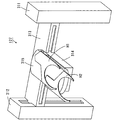
次に、搬送機構127について説明する。図6は、搬送機構127を示す斜視図である。
(B) Configuration of Transport Mechanism Next, the transport mechanism 127 will be described. FIG. 6 is a perspective view showing the transport mechanism 127.

図5および図6に示すように、搬送機構127は、長尺状のガイドレール311,312を備える。図5に示すように、ガイドレール311は、上段搬送室125内において上下方向に延びるように搬送部112側に固定される。ガイドレール312は、上段搬送室125内において上下方向に延びるように上段搬送室135側に固定される。   As shown in FIGS. 5 and 6, the transport mechanism 127 includes long guide rails 311 and 312. As shown in FIG. 5, the guide rail 311 is fixed to the transport unit 112 side so as to extend in the vertical direction in the upper transport chamber 125. The guide rail 312 is fixed to the upper transfer chamber 135 side so as to extend in the vertical direction in the upper transfer chamber 125.

図5および図6に示すように、ガイドレール311とガイドレール312との間には、長尺状のガイドレール313が設けられる。ガイドレール313は、上下動可能にガイドレール311,312に取り付けられる。ガイドレール313に移動部材314が取り付けられる。移動部材314は、ガイドレール313の長手方向に移動可能に設けられる。   As shown in FIGS. 5 and 6, a long guide rail 313 is provided between the guide rail 311 and the guide rail 312. The guide rail 313 is attached to the guide rails 311 and 312 so as to be movable up and down. A moving member 314 is attached to the guide rail 313. The moving member 314 is provided to be movable in the longitudinal direction of the guide rail 313.

移動部材314の上面には、長尺状の回転部材315が回転可能に設けられる。回転部材315には、基板Wを保持するためのハンドH1およびハンドH2が取り付けられる。ハンドH1,H2は、回転部材315の長手方向に移動可能に設けられる。   A long rotating member 315 is rotatably provided on the upper surface of the moving member 314. A hand H1 and a hand H2 for holding the substrate W are attached to the rotating member 315. The hands H1 and H2 are provided so as to be movable in the longitudinal direction of the rotating member 315.

上記のような構成により、搬送機構127は、上段搬送室125内においてX方向およびZ方向に自在に移動することができる。また、ハンドH1,H2を用いて塗布処理室21,22(図2)、基板載置部PASS1,PASS2,PASS5,PASS6(図5)および上段熱処理部301(図4)に対して基板Wの受け渡しを行うことができる。   With the above configuration, the transport mechanism 127 can freely move in the X direction and the Z direction in the upper transport chamber 125. In addition, the hands W1 and H2 are used to apply the substrate W to the coating processing chambers 21 and 22 (FIG. 2), the substrate platforms PASS1, PASS2, PASS5, PASS6 (FIG. 5), and the upper thermal processing unit 301 (FIG. 4). Delivery can be performed.

なお、図5に示すように、搬送機構128,137,138は搬送機構127と同様の構成を有する。   As shown in FIG. 5, the transport mechanisms 128, 137, and 138 have the same configuration as the transport mechanism 127.

(5)インターフェイスブロックの構成
図7は、インターフェイスブロック14の内部構成を示す図である。なお、図7は、インターフェイスブロック14を+X方向側から見た図である。
(5) Configuration of Interface Block FIG. 7 is a diagram showing an internal configuration of the interface block 14. FIG. 7 is a view of the interface block 14 as seen from the + X direction side.

図7に示すように、インターフェイスブロック14の略中央部に2つのバッファBF、基板載置部PASS13および基板載置部PASS−CPが階層的に設けられる。また、基板載置部PASS−CPの−Y方向側に搬送機構141が設けられ、基板載置部PASS−CPの+Y方向側に搬送機構142が設けられる。   As shown in FIG. 7, two buffers BF, a substrate platform PASS13, and a substrate platform PASS-CP are provided in a hierarchical manner at a substantially central portion of the interface block 14. Further, a transport mechanism 141 is provided on the −Y direction side of the substrate platform PASS-CP, and a transport mechanism 142 is provided on the + Y direction side of the substrate platform PASS-CP.

本実施の形態においては、基板載置部PASS−CPに露光処理前の基板Wが載置され、基板載置部PASS13に露光処理後の基板Wが載置される。   In the present embodiment, the substrate W before the exposure process is placed on the substrate platform PASS-CP, and the substrate W after the exposure process is placed on the substrate platform PASS13.

また、図5および図7に示すように、インターフェイスブロック14内の上部には、給気ユニット45が設けられる。給気ユニット45には、図示しない温調装置から温湿度調整された空気が供給される。それにより、給気ユニット45からインターフェイスブロック14内に温湿度調整された清浄な空気が供給される。その結果、インターフェイスブロック14内の雰囲気が適切な温湿度および清浄な状態に維持される。   As shown in FIGS. 5 and 7, an air supply unit 45 is provided in the upper part of the interface block 14. The air supply unit 45 is supplied with air whose temperature and humidity are adjusted from a temperature control device (not shown). Thus, clean air whose temperature and humidity are adjusted is supplied from the air supply unit 45 into the interface block 14. As a result, the atmosphere in the interface block 14 is maintained at an appropriate temperature and humidity and a clean state.

(6)基板処理装置の各構成要素の動作
以下、本実施の形態に係る基板処理装置100の各構成要素の動作について説明する。
(6) Operation of Each Component of Substrate Processing Apparatus Hereinafter, an operation of each component of the substrate processing apparatus 100 according to the present embodiment will be described.

(6−1)インデクサブロック11の動作
以下、図1および図5を主に用いてインデクサブロック11の動作を説明する。
(6-1) Operation of the Indexer Block 11 Hereinafter, the operation of the indexer block 11 will be described mainly using FIG. 1 and FIG.

本実施の形態に係る基板処理装置100においては、まず、インデクサブロック11のキャリア載置部111に、未処理の基板Wが収容されたキャリア113が載置される。搬送機構115は、そのキャリア113から1枚の基板Wを取り出し、その基板Wを基板載置部PASS1に搬送する。その後、搬送機構115はキャリア113から他の1枚の未処理の基板Wを取り出し、その基板Wを基板載置部PASS3(図5)に搬送する。   In the substrate processing apparatus 100 according to the present embodiment, first, the carrier 113 containing the unprocessed substrate W is placed on the carrier placement portion 111 of the indexer block 11. The transport mechanism 115 takes out one substrate W from the carrier 113 and transports the substrate W to the substrate platform PASS1. Thereafter, the transport mechanism 115 takes out another unprocessed substrate W from the carrier 113 and transports the substrate W to the substrate platform PASS3 (FIG. 5).

なお、基板載置部PASS2に処理済みの基板Wが載置されている場合には、搬送機構115は、基板載置部PASS1に未処理の基板Wを搬送した後、基板載置部PASS2からその処理済みの基板Wを取り出す。そして、搬送機構115は、その処理済みの基板Wをキャリア113に搬送する。同様に、基板載置部PASS4に処理済みの基板Wが載置されている場合には、搬送機構115は、基板載置部PASS3に未処理の基板Wを搬送した後、基板載置部PASS4からその処理済みの基板Wを取り出す。そして、搬送機構115は、その処理済み基板Wをキャリア113へ搬送するとともにキャリア113に収容する。   When the processed substrate W is placed on the substrate platform PASS2, the transport mechanism 115 transports the unprocessed substrate W to the substrate platform PASS1, and then from the substrate platform PASS2. The processed substrate W is taken out. Then, the transport mechanism 115 transports the processed substrate W to the carrier 113. Similarly, when the processed substrate W is placed on the substrate platform PASS4, the transport mechanism 115 transports the unprocessed substrate W to the substrate platform PASS3, and then the substrate platform PASS4. Then, the processed substrate W is taken out. The transport mechanism 115 transports the processed substrate W to the carrier 113 and accommodates it in the carrier 113.

(6−2)塗布ブロック12の動作
以下、図1、図2、図4および図5を主に用いて塗布ブロック12の動作について説明する。なお、以下においては、簡便のため、搬送機構127のX方向およびZ方向の移動の説明は省略する。
(6-2) Operation of Application Block 12 Hereinafter, the operation of the application block 12 will be described mainly with reference to FIGS. 1, 2, 4, and 5. In the following, for the sake of simplicity, description of movement of the transport mechanism 127 in the X direction and the Z direction is omitted.

搬送機構115(図5)により基板載置部PASS1(図5)に載置された基板Wは、搬送機構127(図5)のハンドH1により取り出される。また、搬送機構127は、ハンドH2に保持されている基板Wを基板載置部PASS2に載置する。なお、ハンドH2から基板載置部PASS2に載置される基板Wは、現像処理後の基板Wである。   The substrate W placed on the substrate platform PASS1 (FIG. 5) by the transport mechanism 115 (FIG. 5) is taken out by the hand H1 of the transport mechanism 127 (FIG. 5). Further, the transport mechanism 127 places the substrate W held by the hand H2 on the substrate platform PASS2. The substrate W placed on the substrate platform PASS2 from the hand H2 is the substrate W after development processing.

次に、搬送機構127は、ハンドH2により上段熱処理部301(図4)の所定の冷却ユニットCP(図4)から冷却処理後の基板Wを取り出す。また、搬送機構127は、ハンドH1に保持されている未処理の基板Wをその冷却ユニットCPに搬入する。冷却ユニットCPにおいては、反射防止膜形成に適した温度に基板Wが冷却される。   Next, the transport mechanism 127 takes out the substrate W after the cooling process from the predetermined cooling unit CP (FIG. 4) of the upper thermal processing section 301 (FIG. 4) with the hand H2. Further, the transport mechanism 127 carries the unprocessed substrate W held by the hand H1 into the cooling unit CP. In the cooling unit CP, the substrate W is cooled to a temperature suitable for forming the antireflection film.

次に、搬送機構127は、ハンドH1により塗布処理室21(図2)のスピンチャック25(図2)上から反射防止膜形成後の基板Wを取り出す。また、搬送機構127は、ハンドH2に保持されている冷却処理後の基板Wをそのスピンチャック25上に載置する。塗布処理室21においては、塗布処理ユニット129(図2)により、基板W上に反射防止膜が形成される。   Next, the transport mechanism 127 takes out the substrate W after the formation of the antireflection film from the spin chuck 25 (FIG. 2) in the coating processing chamber 21 (FIG. 2) with the hand H <b> 1. Further, the transport mechanism 127 places the substrate W after the cooling process held by the hand H <b> 2 on the spin chuck 25. In the coating processing chamber 21, an antireflection film is formed on the substrate W by the coating processing unit 129 (FIG. 2).

次に、搬送機構127は、ハンドH2により上段熱処理部301の所定の熱処理ユニットPHPから熱処理後の基板Wを取り出す。また、搬送機構127は、ハンドH1に保持されている反射防止膜形成後の基板Wをその熱処理ユニットPHP(図4)に搬入する。熱処理ユニットPHPにおいては、加熱処理部101(図3)および冷却処理部102(図3)により基板Wの加熱処理および冷却処理が連続的に行われる。   Next, the transport mechanism 127 takes out the substrate W after the heat treatment from the predetermined heat treatment unit PHP of the upper heat treatment unit 301 with the hand H2. Further, the transport mechanism 127 carries the substrate W after the formation of the antireflection film held by the hand H1 into the heat treatment unit PHP (FIG. 4). In the heat treatment unit PHP, the heating processing and cooling processing of the substrate W are continuously performed by the heating processing unit 101 (FIG. 3) and the cooling processing unit 102 (FIG. 3).

次に、搬送機構127は、ハンドH1により上段熱処理部301(図4)の所定の冷却ユニットCP(図4)から冷却処理後の基板Wを取り出す。また、搬送機構127は、ハンドH2に保持されている熱処理後の基板Wをその冷却ユニットCPに搬入する。冷却ユニットCPにおいては、レジスト膜形成処理に適した温度に基板Wが冷却される。   Next, the transport mechanism 127 takes out the substrate W after the cooling process from the predetermined cooling unit CP (FIG. 4) of the upper thermal processing section 301 (FIG. 4) with the hand H1. Further, the transport mechanism 127 carries the substrate W after the heat treatment held by the hand H2 into the cooling unit CP. In the cooling unit CP, the substrate W is cooled to a temperature suitable for the resist film forming process.

次に、搬送機構127は、ハンドH2により塗布処理室22(図2)のスピンチャック25(図2)からレジスト膜形成後の基板Wを取り出す。また、搬送機構127は、ハンドH1に保持されている冷却処理後の基板Wをそのスピンチャック25上に載置する。塗布処理室22においては、塗布処理ユニット129(図2)により、基板W上にレジスト膜が形成される。   Next, the transport mechanism 127 takes out the substrate W after the formation of the resist film from the spin chuck 25 (FIG. 2) in the coating processing chamber 22 (FIG. 2) with the hand H2. Further, the transport mechanism 127 places the substrate W after the cooling process held by the hand H <b> 1 on the spin chuck 25. In the coating processing chamber 22, a resist film is formed on the substrate W by the coating processing unit 129 (FIG. 2).

次に、搬送機構127は、ハンドH2に保持されているレジスト膜形成後の基板Wを基板載置部PASS5(図5)に載置するとともに、そのハンドH2により基板載置部PASS6(図5)から現像処理後の基板Wを取り出す。その後、搬送機構127は、基板載置部PASS6から取り出した現像処理後の基板Wを基板載置部PASS2(図5)に搬送する。   Next, the transport mechanism 127 places the substrate W after the resist film formation held by the hand H2 on the substrate platform PASS5 (FIG. 5), and also uses the hand H2 to place the substrate platform PASS6 (FIG. 5). ), The substrate W after the development processing is taken out. Thereafter, the transport mechanism 127 transports the developed substrate W taken out from the substrate platform PASS6 to the substrate platform PASS2 (FIG. 5).

搬送機構127が上記の処理を繰り返すことにより、塗布ブロック12内において複数の基板Wに所定の処理が連続的に行われる。   As the transport mechanism 127 repeats the above processing, predetermined processing is continuously performed on the plurality of substrates W in the coating block 12.

搬送機構128は、搬送機構127と同様の動作により、基板載置部PASS3,PASS4,PASS7,PASS8(図5)、塗布処理室23,24(図2)および下段熱処理部302(図4)に対して基板Wの搬入および搬出を行う。   The transport mechanism 128 is moved into the substrate platforms PASS3, PASS4, PASS7, PASS8 (FIG. 5), the coating processing chambers 23 and 24 (FIG. 2), and the lower heat treatment section 302 (FIG. 4) by the same operation as the transport mechanism 127. On the other hand, the substrate W is carried in and out.

このように、本実施の形態においては、搬送機構127によって搬送される基板Wは、塗布処理室21,22および上段熱処理部301において処理され、搬送機構128によって搬送される基板Wは、塗布処理室23,24および下段熱処理部302において処理される。この場合、複数の基板Wの処理を上方の処理部(塗布処理室21,22および上段熱処理部301)および下方の処理部(塗布処理室23,24および下段熱処理部302)において同時に処理することができる。それにより、搬送機構127,128による基板Wの搬送速度を速くすることなく、塗布ブロック12のスループットを向上させることができる。また、搬送機構127,128が上下に設けられているので、基板処理装置100のフットプリントが増加することを防止することができる。   As described above, in the present embodiment, the substrate W transported by the transport mechanism 127 is processed in the coating processing chambers 21 and 22 and the upper thermal processing section 301, and the substrate W transported by the transport mechanism 128 is processed by the coating process. Processing is performed in the chambers 23 and 24 and the lower heat treatment section 302. In this case, the processing of the plurality of substrates W is simultaneously performed in the upper processing units (coating processing chambers 21 and 22 and the upper thermal processing unit 301) and the lower processing units (coating processing chambers 23 and 24 and the lower thermal processing unit 302). Can do. Thereby, the throughput of the coating block 12 can be improved without increasing the transport speed of the substrate W by the transport mechanisms 127 and 128. In addition, since the transport mechanisms 127 and 128 are provided above and below, an increase in the footprint of the substrate processing apparatus 100 can be prevented.

(6−3)現像ブロック13の動作
以下、図1、図2、図4および図5を主に用いて現像ブロック13の動作について説明する。なお、以下においては、簡便のため、搬送機構137のX方向およびZ方向の移動の説明は省略する。
(6-3) Operation of Development Block 13 Hereinafter, the operation of the development block 13 will be described mainly with reference to FIG. 1, FIG. 2, FIG. 4, and FIG. In the following, for the sake of simplicity, description of movement of the transport mechanism 137 in the X direction and the Z direction is omitted.

搬送機構127により基板載置部PASS5(図5)に載置された基板Wは、搬送機構137(図5)のハンドH1により取り出される。また、搬送機構137は、ハンドH2に保持されている基板Wを基板載置部PASS6に載置する。なお、ハンドH2から基板載置部PASS6に載置される基板Wは、現像ブロック13における処理が終了した基板Wである。   The substrate W placed on the substrate platform PASS5 (FIG. 5) by the transport mechanism 127 is taken out by the hand H1 of the transport mechanism 137 (FIG. 5). Further, the transport mechanism 137 places the substrate W held by the hand H2 on the substrate platform PASS6. The substrate W placed on the substrate platform PASS6 from the hand H2 is the substrate W that has been processed in the developing block 13.

次に、搬送機構137は、ハンドH2により上段熱処理部303(図4)のエッジ露光部EEWからエッジ露光処理後の基板Wを取り出す。また、搬送機構137は、ハンドH1に保持されているレジスト膜形成後の基板Wをエッジ露光部EEWに搬入する。エッジ露光部EEWにおいては、基板Wの周縁部の露光処理が行われる。   Next, the transport mechanism 137 takes out the substrate W after the edge exposure processing from the edge exposure unit EEW of the upper thermal processing unit 303 (FIG. 4) with the hand H2. Also, the transport mechanism 137 carries the substrate W after the resist film formation held by the hand H1 into the edge exposure unit EEW. In the edge exposure unit EEW, exposure processing of the peripheral portion of the substrate W is performed.

次に、搬送機構137は、ハンドH2に保持されているエッジ露光処理後の基板Wを基板載置部PASS9(図4)に載置するとともに、そのハンドH2により基板載置部PASS10(図4)から露光処理後の基板Wを取り出す。なお、基板載置部PASS10から取り出される基板Wは、露光装置15における露光処理が終了した基板Wである。   Next, the transport mechanism 137 places the substrate W after edge exposure processing held by the hand H2 on the substrate platform PASS9 (FIG. 4), and also uses the hand H2 to place the substrate platform PASS10 (FIG. 4). ), The substrate W after the exposure processing is taken out. The substrate W taken out from the substrate platform PASS10 is the substrate W that has been subjected to the exposure processing in the exposure apparatus 15.

次に、搬送機構137は、ハンドH1により上段熱処理部303(図4)の所定の冷却ユニットCP(図4)から冷却処理後の基板Wを取り出す。また、搬送機構137は、ハンドH2に保持されている露光処理後の基板Wをその冷却ユニットCPに搬入する。   Next, the transport mechanism 137 takes out the substrate W after the cooling process from the predetermined cooling unit CP (FIG. 4) of the upper thermal processing section 303 (FIG. 4) with the hand H <b> 1. Further, the transport mechanism 137 carries the substrate W after the exposure processing held by the hand H2 into the cooling unit CP.

次に、搬送機構137は、ハンドH2により現像処理室31(図2)または現像処理室32(図2)のスピンチャック35(図2)から現像処理後の基板Wを取り出す。また、搬送機構137は、ハンドH1に保持されている冷却処理後の基板Wをそのスピンチャック25上に載置する。現像処理室31,32においては、現像処理ユニット139により基板Wの現像処理が行われる。   Next, the transport mechanism 137 takes out the substrate W after the development processing from the spin chuck 35 (FIG. 2) of the development processing chamber 31 (FIG. 2) or the development processing chamber 32 (FIG. 2) with the hand H2. Further, the transport mechanism 137 places the cooled substrate W held by the hand H1 on the spin chuck 25. In the development processing chambers 31 and 32, the development processing unit 139 performs development processing on the substrate W.

次に、搬送機構137は、ハンドH1により上段熱処理部303(図4)の所定の加熱ユニットHPから加熱処理後の基板Wを取り出す。また、搬送機構137は、ハンドH2に保持されている現像処理後の基板Wを加熱ユニットHPに搬入する。加熱ユニットHPにおいては、基板Wの加熱処理が行われる。   Next, the transport mechanism 137 takes out the substrate W after the heat treatment from the predetermined heating unit HP of the upper heat treatment section 303 (FIG. 4) with the hand H1. Further, the transport mechanism 137 carries the substrate W after the development processing held by the hand H2 into the heating unit HP. In the heating unit HP, the substrate W is heated.

次に、搬送機構137は、ハンドH2により上段熱処理部303(図4)の所定の冷却ユニットCPから冷却処理後の基板Wを取り出す。また、搬送機構137は、ハンドH1に保持されている基板Wをその冷却ユニットCPに搬入する。その後、搬送機構137は、冷却ユニットCPから取り出した基板Wを基板W基板載置部PASS6(図5)に搬送する。   Next, the transport mechanism 137 takes out the substrate W after the cooling processing from the predetermined cooling unit CP of the upper thermal processing section 303 (FIG. 4) with the hand H2. The transport mechanism 137 carries the substrate W held by the hand H1 into the cooling unit CP. Thereafter, the transport mechanism 137 transports the substrate W taken out from the cooling unit CP to the substrate W substrate platform PASS6 (FIG. 5).

搬送機構137が上記の処理を繰り返すことにより、現像ブロック13内において複数の基板Wに所定の処理が連続的に行われる。   The transport mechanism 137 repeats the above processing, whereby predetermined processing is continuously performed on the plurality of substrates W in the development block 13.

搬送機構138は、搬送機構137と同様の動作により、基板載置部PASS7,PASS8(図5)、基板載置部PASS11,PASS12(図4)、塗布処理室33,34(図2)および下段熱処理部304(図4)に対して基板Wの搬入および搬出を行う。   The transport mechanism 138 is operated in the same manner as the transport mechanism 137, so that the substrate platforms PASS7 and PASS8 (FIG. 5), the substrate platforms PASS11 and PASS12 (FIG. 4), the coating processing chambers 33 and 34 (FIG. 2), and the lower stage. The substrate W is carried into and out of the heat treatment unit 304 (FIG. 4).

このように、本実施の形態においては、搬送機構137によって搬送される基板Wは、現像処理室31,32および上段熱処理部303において処理され、搬送機構138によって搬送される基板Wは、現像処理室33,34および下段熱処理部304において処理される。この場合、複数の基板Wの処理を上方の処理部(現像処理室31,32および上段熱処理部303)および下方の処理部(現像処理室33,34および下段熱処理部304)において同時に処理することができる。それにより、搬送機構137,138による基板Wの搬送速度を速くすることなく、現像ブロック13のスループットを向上させることができる。また、搬送機構137,138が上下に設けられているので、基板処理装置100のフットプリントが増加することを防止することができる。   As described above, in this embodiment, the substrate W transported by the transport mechanism 137 is processed in the development processing chambers 31 and 32 and the upper thermal processing section 303, and the substrate W transported by the transport mechanism 138 is developed. Processing is performed in the chambers 33 and 34 and the lower heat treatment section 304. In this case, a plurality of substrates W are simultaneously processed in the upper processing units (development processing chambers 31 and 32 and the upper thermal processing unit 303) and the lower processing units (development processing chambers 33 and 34 and the lower thermal processing unit 304). Can do. Thereby, the throughput of the developing block 13 can be improved without increasing the transport speed of the substrate W by the transport mechanisms 137 and 138. In addition, since the transport mechanisms 137 and 138 are provided above and below, an increase in the footprint of the substrate processing apparatus 100 can be prevented.

(6−4)インターフェイスブロック14の動作
以下、図7を主に用いてインターフェイスブロック14の動作について説明する。
(6-4) Operation of Interface Block 14 The operation of the interface block 14 will be described below mainly using FIG.

まず、搬送機構141の動作について説明する。搬送機構137(図5)により基板載置部PASS9に載置された露光処理前(エッジ露光後)の基板Wは、搬送機構141により取り出され、基板載置部PASS−CPに搬送される。基板載置部PASS−CPにおいては、露光装置15(図1)における露光処理に適した温度に基板Wが冷却される。   First, the operation of the transport mechanism 141 will be described. The substrate W before exposure processing (after edge exposure) placed on the substrate platform PASS9 by the transport mechanism 137 (FIG. 5) is taken out by the transport mechanism 141 and transported to the substrate platform PASS-CP. In the substrate platform PASS-CP, the substrate W is cooled to a temperature suitable for the exposure process in the exposure apparatus 15 (FIG. 1).

その後、搬送機構141は、基板載置部PASS13に載置されている露光処理後の基板Wを取り出し、その基板Wを現像ブロック13(図5)の上段熱処理部303の所定の熱処理ユニットPHPに搬送する。熱処理ユニットPHPにおいては、露光処理後の基板Wに熱処理が行われる。   Thereafter, the transport mechanism 141 takes out the substrate W after the exposure processing placed on the substrate platform PASS13, and places the substrate W on a predetermined thermal processing unit PHP in the upper thermal processing section 303 of the development block 13 (FIG. 5). Transport. In the heat treatment unit PHP, heat treatment is performed on the substrate W after the exposure processing.

次に、搬送機構141は、上段熱処理部303の他の熱処理ユニットPHPから熱処理済みの基板Wを取り出し、その基板Wを基板載置部PASS10に載置する。基板載置部PASS10に載置された基板Wは、上述したように、現像ブロック13(図5)の搬送機構137(図5)により取り出される。これにより、露光処理後の基板Wのインターフェイスブロック14から現像ブロック13への受け渡しが完了する。   Next, the transport mechanism 141 takes out the heat-treated substrate W from another heat treatment unit PHP of the upper heat treatment section 303 and places the substrate W on the substrate platform PASS10. As described above, the substrate W placed on the substrate platform PASS10 is taken out by the transport mechanism 137 (FIG. 5) of the development block 13 (FIG. 5). Thereby, the delivery of the substrate W after the exposure processing from the interface block 14 to the developing block 13 is completed.

次に、搬送機構141は、搬送機構138(図5)により基板載置部PASS11に載置された露光処理前(エッジ露光後)の基板Wを取り出し、その基板Wを基板載置部PASS−CPに搬送する。その後、搬送機構141は、基板載置部PASS13に載置されている露光処理後の基板Wを取り出し、その基板Wを現像ブロック13(図5)の下段熱処理部304の所定の熱処理ユニットPHPに搬送する。   Next, the transport mechanism 141 takes out the substrate W before exposure processing (after edge exposure) placed on the substrate platform PASS11 by the transport mechanism 138 (FIG. 5), and removes the substrate W from the substrate platform PASS−. Transport to CP. Thereafter, the transport mechanism 141 takes out the substrate W after the exposure processing placed on the substrate platform PASS13, and puts the substrate W on a predetermined thermal processing unit PHP in the lower thermal processing section 304 of the development block 13 (FIG. 5). Transport.

次に、搬送機構141は、下段熱処理部304の他の熱処理ユニットPHPから熱処理済みの基板Wを取り出し、その基板Wを基板載置部PASS12に載置する。基板載置部PASS12に載置された基板Wは、現像ブロック13(図5)の搬送機構138(図5)により取り出される。これにより、露光処理後の基板Wのインターフェイスブロック14から現像ブロック13への受け渡しが完了する。   Next, the transport mechanism 141 takes out the heat-treated substrate W from the other heat treatment unit PHP of the lower heat treatment unit 304 and places the substrate W on the substrate platform PASS12. The substrate W placed on the substrate platform PASS12 is taken out by the transport mechanism 138 (FIG. 5) of the development block 13 (FIG. 5). Thereby, the delivery of the substrate W after the exposure processing from the interface block 14 to the developing block 13 is completed.

搬送機構141は、上記の動作を繰り返す。それにより、インターフェイスブロック14と上段熱処理部303との間での基板Wの受け渡しおよびインターフェイスブロック14と下段熱処理部304との間での基板Wの受け渡しが交互に行われる。   The transport mechanism 141 repeats the above operation. Thereby, the delivery of the substrate W between the interface block 14 and the upper thermal processing section 303 and the delivery of the substrate W between the interface block 14 and the lower thermal processing section 304 are alternately performed.

ここで、本実施の形態においては、キャリア113(図5)に収容されている基板Wは、搬送機構115(図5)により基板載置部PASS1,PASS3(図2)に交互に搬送される。また、塗布処理室21,22(図2)および上段熱処理部301(図4)における基板Wの処理速度と、塗布処理室23,24(図2)および下段熱処理部302(図4)における基板Wの処理速度とは略等しい。また、搬送機構127(図5)の動作速度と搬送機構128(図5)の動作速度とは略等しい。また、現像処理室31,32(図2)および上段熱処理部303(図4)における基板Wの処理速度と、現像処理室33,34(図2)および下段熱処理部304(図4)における基板Wの処理速度とは略等しい。また、搬送機構137(図5)の動作速度と搬送機構138(図5)の動作速度とは略等しい。   Here, in the present embodiment, the substrates W accommodated in the carrier 113 (FIG. 5) are alternately transported to the substrate platforms PASS1, PASS3 (FIG. 2) by the transport mechanism 115 (FIG. 5). . Further, the processing speed of the substrate W in the coating processing chambers 21 and 22 (FIG. 2) and the upper thermal processing section 301 (FIG. 4), and the substrate in the coating processing chambers 23 and 24 (FIG. 2) and the lower thermal processing section 302 (FIG. 4). The processing speed of W is substantially equal. Further, the operating speed of the transport mechanism 127 (FIG. 5) and the operating speed of the transport mechanism 128 (FIG. 5) are substantially equal. Further, the processing speed of the substrate W in the development processing chambers 31, 32 (FIG. 2) and the upper thermal processing section 303 (FIG. 4), and the substrate in the development processing chambers 33, 34 (FIG. 2) and the lower thermal processing section 304 (FIG. 4). The processing speed of W is substantially equal. Further, the operating speed of the transport mechanism 137 (FIG. 5) and the operating speed of the transport mechanism 138 (FIG. 5) are substantially equal.

したがって、上記のように上段熱処理部303および下段熱処理部304から基板載置部PASS−CPに基板Wが交互に搬送されることにより、キャリア113から基板処理装置100に搬入される基板Wの順序と、現像ブロック13(図5)から基板載置部PASS−CPに搬送される基板Wの順序とが一致する。この場合、基板処理装置100における各基板Wの処理履歴の管理が容易になる。   Therefore, the order of the substrates W carried into the substrate processing apparatus 100 from the carrier 113 by alternately transferring the substrates W from the upper thermal processing unit 303 and the lower thermal processing unit 304 to the substrate platform PASS-CP as described above. And the order of the substrates W transported from the developing block 13 (FIG. 5) to the substrate platform PASS-CP. In this case, the management of the processing history of each substrate W in the substrate processing apparatus 100 is facilitated.

なお、バッファBFは、基板載置部PASS9,PASS11から基板載置部PASS−CPへ基板Wを交互に搬送することができない場合に用いられる。具体的には、例えば、塗布処理室21,22(図2)の塗布処理ユニット129(図2)に不具合が発生することにより基板載置部PASS9への基板Wの搬送が停止されている場合にバッファBFが用いられる。この場合、搬送機構141は、基板載置部PASS9に基板Wが搬送されるまで、基板載置部PASS11に載置された基板WをバッファBFに搬送する。そして、基板載置部PASS9への基板Wの搬送が再開された場合には、搬送機構141は、基板載置部PASS9から基板載置部PASS−CPへの基板Wの搬送およびバッファBFから基板載置部PASS−CPへの基板Wの搬送を交互に行う。それにより、キャリア113から基板処理装置100に搬入される基板Wの順序と、現像ブロック13から基板載置部PASS−CPに搬送される基板Wの順序とを一致させることができる。なお、基板載置部PASS11への基板Wの搬送が停止されている場合には、搬送機構141は、基板載置部PASS11への基板Wの搬送が再開されるまで、基板載置部PASS9に載置された基板WをバッファBFに搬送する。   The buffer BF is used when the substrates W cannot be alternately transferred from the substrate platforms PASS9 and PASS11 to the substrate platform PASS-CP. Specifically, for example, when the conveyance of the substrate W to the substrate platform PASS9 is stopped due to a failure in the coating processing unit 129 (FIG. 2) in the coating processing chambers 21 and 22 (FIG. 2). Buffer BF is used. In this case, the transport mechanism 141 transports the substrate W placed on the substrate platform PASS11 to the buffer BF until the substrate W is transported to the substrate platform PASS9. When the transport of the substrate W to the substrate platform PASS9 is resumed, the transport mechanism 141 transports the substrate W from the substrate platform PASS9 to the substrate platform PASS-CP and the substrate from the buffer BF. The substrate W is alternately transferred to the placement unit PASS-CP. Thereby, the order of the substrates W carried into the substrate processing apparatus 100 from the carrier 113 can be matched with the order of the substrates W transported from the developing block 13 to the substrate platform PASS-CP. When the transport of the substrate W to the substrate platform PASS11 is stopped, the transport mechanism 141 moves the substrate platform PASS9 until the transport of the substrate W to the substrate platform PASS11 is resumed. The mounted substrate W is transferred to the buffer BF.

次に、搬送機構142の動作について説明する。   Next, the operation of the transport mechanism 142 will be described.

搬送機構141により基板載置部PASS−CPに載置された基板Wは、所定の温度に冷却された後、搬送機構142により取り出される。搬送機構142は、その基板Wを露光装置15(図1)に搬入する。   The substrate W placed on the substrate platform PASS-CP by the transport mechanism 141 is cooled to a predetermined temperature and then taken out by the transport mechanism 142. The transport mechanism 142 carries the substrate W into the exposure device 15 (FIG. 1).

次に、搬送機構142は、露光装置15から露光処理後の基板Wを搬出し、その基板Wを基板載置部PASS13に載置する。基板載置部PASS13に載置された基板Wは、上述したように、搬送機構141により熱処理ユニットPHPへ搬送される。   Next, the transport mechanism 142 unloads the substrate W after the exposure processing from the exposure apparatus 15 and places the substrate W on the substrate platform PASS13. As described above, the substrate W placed on the substrate platform PASS13 is transported to the heat treatment unit PHP by the transport mechanism 141.

搬送機構142は上記の処理を繰り返す。ここで、上述したように搬送機構141によって基板載置部PASS−CPに載置される基板Wの順序は、キャリア113(図5)から基板処理装置100に搬入される基板Wの順序に等しい。それにより、キャリア113から基板処理装置100に搬入される基板Wの順序と、搬送機構142により露光装置15に搬入される基板Wの順序とを一致させることができる。それにより、露光装置15における各基板Wの処理履歴の管理が容易になる。また、一のキャリア113から基板処理装置100に搬入された複数の基板W間において、露光処理の状態にばらつきが生じることを防止することができる。   The transport mechanism 142 repeats the above processing. Here, as described above, the order of the substrates W placed on the substrate platform PASS-CP by the transport mechanism 141 is equal to the order of the substrates W carried into the substrate processing apparatus 100 from the carrier 113 (FIG. 5). . Thereby, the order of the substrates W carried into the substrate processing apparatus 100 from the carrier 113 and the order of the substrates W carried into the exposure apparatus 15 by the transport mechanism 142 can be matched. This facilitates management of the processing history of each substrate W in the exposure apparatus 15. In addition, it is possible to prevent variation in the state of the exposure processing among the plurality of substrates W carried into the substrate processing apparatus 100 from the one carrier 113.

(7)給気ユニット41の構成
次に、給気ユニット41の構成について詳細に説明する。
(7) Configuration of Air Supply Unit 41 Next, the configuration of the air supply unit 41 will be described in detail.

図8は、各塗布処理室21〜24(図2)に設けられる給気ユニット41を示す概略図である。なお、図8において(a)は、給気ユニット41の側面図であり、(b)は、(a)のA−A線断面図である。   FIG. 8 is a schematic view showing an air supply unit 41 provided in each of the coating processing chambers 21 to 24 (FIG. 2). In addition, in FIG. 8, (a) is a side view of the air supply unit 41, (b) is the sectional view on the AA line of (a).

図8に示すように、給気ユニット41は、箱状の空気流通部91、その空気流通部91の下面に設けられる流量調整板92,93およびその流量調整板92,93の下面に設けられるフィルタ装置94,95を含む。フィルタ装置94,95としては、例えば、ULPA(Ultra Low Penetration Air)フィルタを用いることができる。   As shown in FIG. 8, the air supply unit 41 is provided on a box-shaped air circulation portion 91, flow rate adjustment plates 92 and 93 provided on the lower surface of the air circulation portion 91, and lower surfaces of the flow rate adjustment plates 92 and 93. Filter devices 94 and 95 are included. As the filter devices 94 and 95, for example, an ULPA (Ultra Low Penetration Air) filter can be used.

空気流通部91の一端側に流通管51が接続される。それにより、空気流通部91の内部空間と流通管51の内部空間とが連通される。流量調整ダンパ46は、流通管51と空気流通部91との接続部に設けられる。   A flow pipe 51 is connected to one end side of the air flow portion 91. Thereby, the internal space of the air circulation part 91 and the internal space of the flow pipe 51 are communicated. The flow rate adjustment damper 46 is provided at a connection portion between the flow pipe 51 and the air flow portion 91.

図8(b)に示すように、空気流通部91の下面の一端側(流通管51側)に正方形の開口912が形成され、空気流通部91の下面の他端側に正方形の開口913が形成される。開口912は、塗布処理ユニット129の一方のカップ27の上方に形成され、開口913は他方のカップ27の上方に形成される。なお、本実施の形態においては、開口912のXY平面における面積と開口913のXY平面における面積は等しい。   As shown in FIG. 8 (b), a square opening 912 is formed on one end side (flow pipe 51 side) of the lower surface of the air circulation portion 91, and a square opening 913 is formed on the other end side of the lower surface of the air circulation portion 91. It is formed. The opening 912 is formed above one cup 27 of the coating processing unit 129, and the opening 913 is formed above the other cup 27. In the present embodiment, the area of the opening 912 in the XY plane is equal to the area of the opening 913 in the XY plane.

流量調整板92は、開口912を塞ぐように空気流通部91の下面側に取り付けられ、流量調整板93は、開口913を塞ぐように空気流通部91の下面側に取り付けられる。流量調整板92,93には、複数の貫通孔96がそれぞれ形成される。流通管51から空気流通部91内に流入した空気は、複数の貫通孔96(図8(b))およびフィルタ装置94,95(図8(a))を通過して各塗布処理室21〜24内に流入する。   The flow rate adjusting plate 92 is attached to the lower surface side of the air circulation portion 91 so as to close the opening 912, and the flow rate adjusting plate 93 is attached to the lower surface side of the air circulation portion 91 so as to close the opening 913. A plurality of through holes 96 are formed in the flow rate adjusting plates 92 and 93, respectively. The air that has flowed into the air circulation portion 91 from the circulation pipe 51 passes through the plurality of through holes 96 (FIG. 8B) and the filter devices 94 and 95 (FIG. 8A) to each of the coating treatment chambers 21 to 21. 24 flows in.

ここで、流量調整板92,93の上面には、それぞれ複数(本実施の形態においては3本)の断面四角形状の気流調整部材97が設けられる。本実施の形態においては、気流調整部材97は棒状の形状を有し、Y方向に延びるように設けられる。この複数の気流調整部材97は、流通管51から空気流通部91内に流入した空気が空気流通部91内を−X方向に向かって直進することを防止する。   Here, a plurality (three in the present embodiment) of air flow adjusting members 97 each having a quadrangular cross section are provided on the upper surfaces of the flow rate adjusting plates 92 and 93. In the present embodiment, the airflow adjustment member 97 has a rod shape and is provided so as to extend in the Y direction. The plurality of airflow adjusting members 97 prevent the air flowing into the air circulation portion 91 from the circulation pipe 51 from going straight in the air circulation portion 91 in the −X direction.

この場合、空気流通部91内において流量調整板92上と流量調整板93上とで空気の流速に差が生じることを防止することができる。それにより、流量調整板92の複数の貫通孔96を通過する空気の量と流量調整板93の複数の貫通孔96を通過する空気の量とに差が生じることを防止することができる。したがって、フィルタ装置94の下方のカップ27およびフィルタ装置95の下方のカップ27に同等の量の空気を供給することができる。その結果、2つのカップ27において基板Wを均一に処理することが可能になる。   In this case, it is possible to prevent a difference in the air flow rate between the flow rate adjustment plate 92 and the flow rate adjustment plate 93 in the air circulation portion 91. Thereby, it is possible to prevent the difference between the amount of air passing through the plurality of through holes 96 of the flow rate adjusting plate 92 and the amount of air passing through the plurality of through holes 96 of the flow rate adjusting plate 93. Therefore, an equivalent amount of air can be supplied to the cup 27 below the filter device 94 and the cup 27 below the filter device 95. As a result, the substrate W can be uniformly processed in the two cups 27.

なお、流量調整板92に形成される複数の貫通孔96の合計の面積が、流量調整板93に形成される複数の貫通孔96の合計の面積よりも大きいことが好ましい。すなわち、空気流通部91内の上流側(流通管51側)に配置される流量調整板92の開口面積が下流側に配置される流量調整板93の開口面積よりも大きいことが好ましい。   The total area of the plurality of through holes 96 formed in the flow rate adjusting plate 92 is preferably larger than the total area of the plurality of through holes 96 formed in the flow rate adjusting plate 93. That is, it is preferable that the opening area of the flow rate adjusting plate 92 arranged on the upstream side (flowing pipe 51 side) in the air circulation portion 91 is larger than the opening area of the flow rate adjusting plate 93 arranged on the downstream side.

この場合、流量調整板92の複数の貫通孔96を通過する空気の量と流量調整板93の複数の貫通孔96を通過する空気の量とに差が生じることを十分に防止することができる。それにより、塗布処理ユニット129の2つのカップ27に均一に空気を供給することができる。その結果、塗布処理ユニット129における基板Wのより均一な処理が可能になる。   In this case, it is possible to sufficiently prevent the difference between the amount of air passing through the plurality of through holes 96 of the flow rate adjusting plate 92 and the amount of air passing through the plurality of through holes 96 of the flow rate adjusting plate 93. . Thereby, air can be uniformly supplied to the two cups 27 of the coating processing unit 129. As a result, more uniform processing of the substrate W in the coating processing unit 129 becomes possible.

本実施の形態においては、例えば、流量調整板92に形成される複数の貫通孔96の合計の面積は開口912の面積の60〜80%の大きさに設定され、流量調整板93に形成される複数の貫通孔96の合計の面積は開口913の面積の5〜10%の大きさに設定される。   In the present embodiment, for example, the total area of the plurality of through holes 96 formed in the flow rate adjusting plate 92 is set to 60 to 80% of the area of the opening 912 and formed in the flow rate adjusting plate 93. The total area of the plurality of through holes 96 is set to 5 to 10% of the area of the opening 913.

なお、流量調整板92に形成される複数の貫通孔96の合計の面積および流量調整板93に形成される複数の貫通孔96の合計の面積は、貫通孔96の数によって調整してもよく、貫通孔96の直径によって調整してもよい。   The total area of the plurality of through holes 96 formed in the flow rate adjusting plate 92 and the total area of the plurality of through holes 96 formed in the flow rate adjusting plate 93 may be adjusted by the number of through holes 96. The diameter of the through hole 96 may be adjusted.

また、気流調整部材97のZ方向における高さは、空気流通部91の内部空間のZ方向における高さの20%〜30%に設定されることが好ましい。   The height of the airflow adjusting member 97 in the Z direction is preferably set to 20% to 30% of the height of the internal space of the air circulation portion 91 in the Z direction.

なお、上記においては、各塗布処理室21〜24に設けられる給気ユニット41について説明したが、各現像処理室31〜34に設けられる給気ユニット41も同様の構成を有する。したがって、本実施の形態においては、現像処理ユニット139(図2)においても、2つのカップ37において基板Wを均一に処理することができる。   In the above description, the air supply unit 41 provided in each of the coating processing chambers 21 to 24 has been described. However, the air supply unit 41 provided in each of the development processing chambers 31 to 34 has the same configuration. Therefore, in the present embodiment, the substrate W can be processed uniformly in the two cups 37 even in the development processing unit 139 (FIG. 2).

なお、気流調整部材97によって空気流通部91内の空気の流速を十分に安定させることができる場合には、流量調整板92,93が設けられなくてもよい。   In addition, when the air flow rate adjustment member 97 can sufficiently stabilize the flow rate of the air in the air circulation portion 91, the flow rate adjustment plates 92 and 93 may not be provided.

(8)給気ユニット43の構成
次に、給気ユニット43の構成について説明する。
(8) Configuration of Air Supply Unit 43 Next, the configuration of the air supply unit 43 will be described.

図9は、上段搬送室125(図5)に設けられる給気ユニット43を示す概略図である。なお、図9において、(a)は、給気ユニット43の側面図であり、(b)は、(a)のA−A線断面図である。   FIG. 9 is a schematic view showing an air supply unit 43 provided in the upper transfer chamber 125 (FIG. 5). In addition, in FIG. 9, (a) is a side view of the air supply unit 43, (b) is the sectional view on the AA line of (a).

図9に示すように、給気ユニット43は、箱状の空気流通部201およびその空気流通部201の下面に設けられるフィルタ装置202,203を含む。フィルタ装置202,203としては、例えば、ULPAフィルタを用いることができる。なお、空気流通部201は、移動部材314の移動経路上に設けられる。   As shown in FIG. 9, the air supply unit 43 includes a box-shaped air circulation unit 201 and filter devices 202 and 203 provided on the lower surface of the air circulation unit 201. As the filter devices 202 and 203, for example, ULPA filters can be used. The air circulation unit 201 is provided on the moving path of the moving member 314.

図9(b)に示すように、空気流通部201内には、スリット板204が設けられる。空気流通部201内は、スリット板204により流通空間205および流入空間206に分割される。空気流通部201の一端側には、流通空間205と連通するように流通管72が接続される。スリット板204には、複数(本実施の形態においては8つ)のスリット207が等間隔で形成されている。また、スリット板204には、複数の移動板701がX方向に移動可能に設けられている。本実施の形態においては、各移動板701を移動させることにより、各スリット207の大きさを調整することができる。   As shown in FIG. 9B, a slit plate 204 is provided in the air circulation unit 201. The air circulation part 201 is divided into a circulation space 205 and an inflow space 206 by the slit plate 204. A flow pipe 72 is connected to one end side of the air flow part 201 so as to communicate with the flow space 205. In the slit plate 204, a plurality (eight in this embodiment) of slits 207 are formed at equal intervals. The slit plate 204 is provided with a plurality of moving plates 701 that can move in the X direction. In the present embodiment, the size of each slit 207 can be adjusted by moving each moving plate 701.

空気流通部201内において流入空間206には、仕切り板208が設けられる。仕切り板208は、流入空間206のX方向における中央部に設けられる。流入空間206は、仕切り板208により第1の流入空間601および第2の流入空間602に分割される。本実施の形態においては、第1の流入空間601の容積および第2の流入空間602の容積は等しい。   A partition plate 208 is provided in the inflow space 206 in the air circulation unit 201. The partition plate 208 is provided at the center of the inflow space 206 in the X direction. The inflow space 206 is divided into a first inflow space 601 and a second inflow space 602 by the partition plate 208. In the present embodiment, the volume of the first inflow space 601 and the volume of the second inflow space 602 are equal.

空気流通部201において第1の流入空間601の下方には開口209が形成され、空気流通部201において第2の流入空間602の下方には開口210が形成される。なお、本実施の形態においては、開口209のXY平面における面積と開口210のXY平面における面積とは等しい。   An opening 209 is formed below the first inflow space 601 in the air circulation part 201, and an opening 210 is formed below the second inflow space 602 in the air circulation part 201. In the present embodiment, the area of the opening 209 in the XY plane is equal to the area of the opening 210 in the XY plane.

フィルタ装置202は、開口209を塞ぐように空気流通部201の下面側に取り付けられ、フィルタ装置203は、開口210を塞ぐように空気流通部201の下面側に取り付けられる。流通管72から流通空間205に流入した空気は、スリット板204の複数のスリット207を通過して第1の流入空間601および第2の流入空間602に流入した後、フィルタ装置202,203から上段搬送室125に供給される。   The filter device 202 is attached to the lower surface side of the air circulation portion 201 so as to close the opening 209, and the filter device 203 is attached to the lower surface side of the air circulation portion 201 so as to close the opening 210. The air that has flowed into the flow space 205 from the flow pipe 72 passes through the plurality of slits 207 of the slit plate 204 and flows into the first flow-in space 601 and the second flow-in space 602, and then the upper stage from the filter devices 202 and 203. It is supplied to the transfer chamber 125.

ここで、本実施の形態においては、仕切り板208により第1の流入空間601から第2の流入空間602に空気が流入することを防止することができる。それにより、第1の流入空間601における空気の流速に比べて第2の流入空間602における空気の流速が速くなることを防止することができる。   Here, in the present embodiment, the partition plate 208 can prevent air from flowing from the first inflow space 601 into the second inflow space 602. Accordingly, it is possible to prevent the air flow velocity in the second inflow space 602 from becoming higher than the air flow velocity in the first inflow space 601.

この場合、フィルタ装置202を介して上段搬送室125(図5)に供給される空気量とフィルタ装置203を介して上段搬送室125に供給される空気量とに差が生じることを防止することができる。したがって、移動部材314の移動経路上に均一に空気を供給することが可能となる。それにより、上段搬送室125内において基板Wが搬送される際に基板Wの周辺の温湿度が変化することを防止することができる。その結果、基板Wの高精度な処理が可能となる。   In this case, it is possible to prevent a difference between the amount of air supplied to the upper transfer chamber 125 (FIG. 5) via the filter device 202 and the amount of air supplied to the upper transfer chamber 125 via the filter device 203. Can do. Therefore, air can be supplied uniformly on the moving path of the moving member 314. Thereby, it is possible to prevent the temperature and humidity around the substrate W from changing when the substrate W is transported in the upper transport chamber 125. As a result, the substrate W can be processed with high accuracy.

また、本実施の形態においては、流通空間205と第1の流入空間601とを連通させる複数のスリット207の合計の面積が流通空間205と第2の流入空間602とを連通させる複数のスリット207の合計の面積よりも大きくなるように、複数の移動板701が設定される。   Further, in the present embodiment, the total area of the plurality of slits 207 that connect the circulation space 205 and the first inflow space 601 is the plurality of slits 207 that connect the circulation space 205 and the second inflow space 602. A plurality of moving plates 701 are set so as to be larger than the total area.

この場合、第1の流入空間601における空気の流速に比べて第2の流入空間602における空気の流速が速くなることを十分に防止することができる。それにより、第1の流入空間601における空気の流速および第2の流入空間602における空気の流速を均一化することができる。その結果、基板処理装置100における基板Wの処理性能をさらに向上させることができる。   In this case, it is possible to sufficiently prevent the air flow rate in the second inflow space 602 from becoming higher than the air flow rate in the first inflow space 601. Thereby, the flow velocity of air in the first inflow space 601 and the flow velocity of air in the second inflow space 602 can be made uniform. As a result, the processing performance of the substrate W in the substrate processing apparatus 100 can be further improved.

なお、本実施の形態においては、流通空間205と第1の流入空間601とを連通させる複数のスリット207の合計の面積と流通空間205と第2の流入空間602とを連通させる複数のスリット207の合計の面積との比が、例えば、10:8に設定される。   In the present embodiment, the total area of the plurality of slits 207 that allow the circulation space 205 and the first inflow space 601 to communicate with each other and the plurality of slits 207 that allow the circulation space 205 and the second inflow space 602 to communicate with each other. The ratio to the total area is set to 10: 8, for example.

なお、上記においては、上段搬送室125に設けられる給気ユニット43について説明したが、下段搬送室126、上段搬送室135および下段搬送室136に設けられる給気ユニット43も同様の構成を有する。   Although the air supply unit 43 provided in the upper transfer chamber 125 has been described above, the air supply unit 43 provided in the lower transfer chamber 126, the upper transfer chamber 135, and the lower transfer chamber 136 has the same configuration.

(9)排気ユニット44の構成
次に、排気ユニット44の構成について説明する。
(9) Configuration of Exhaust Unit 44 Next, the configuration of the exhaust unit 44 will be described.

図10は、上段搬送室125(図5)に設けられる排気ユニット44を示す概略図である。なお、図10において、(a)は、排気ユニット44の側面図であり、(b)は、排気ユニット44の上面図である。   FIG. 10 is a schematic view showing the exhaust unit 44 provided in the upper transfer chamber 125 (FIG. 5). 10A is a side view of the exhaust unit 44, and FIG. 10B is a top view of the exhaust unit 44. FIG.

図10に示すように、排気ユニット44は、箱状の空気流入部400を有する。空気流入部400と図9の空気流通部201とは、搬送機構127(図9(a))を挟んで対向するように設けられる。   As shown in FIG. 10, the exhaust unit 44 has a box-shaped air inflow portion 400. The air inflow part 400 and the air circulation part 201 in FIG. 9 are provided so as to face each other with the transport mechanism 127 (FIG. 9A) interposed therebetween.

図10(a)に示すように、空気流入部400の下面の一端側に流通管77が接続される。より具体的には、図10(b)に示すように、流通管77は、空気流入部400の下面の角部に接続される。   As shown in FIG. 10A, the flow pipe 77 is connected to one end side of the lower surface of the air inflow portion 400. More specifically, as shown in FIG. 10B, the flow pipe 77 is connected to a corner portion on the lower surface of the air inflow portion 400.

空気流入部400の上面には、一端側から順に第1領域401、第2領域402および第3領域403が設けられる。第1領域401〜第3領域403の面積は略等しい。   A first region 401, a second region 402, and a third region 403 are provided on the upper surface of the air inflow portion 400 in order from one end side. The areas of the first region 401 to the third region 403 are substantially equal.

空気流入部400の上面には、空気流入部400の外部と内部空間とを連通させる複数の貫通孔404が形成される。本実施の形態においては、第1領域401〜第3領域403にそれぞれ同数の貫通孔404が形成される。なお、第1領域401内において複数の貫通孔404は互いに等間隔に配置されている。同様に、第2領域402および第3領域403内において複数の貫通孔は互いに等間隔に配置されている。   A plurality of through holes 404 are formed on the upper surface of the air inflow portion 400 to communicate the outside of the air inflow portion 400 with the internal space. In the present embodiment, the same number of through holes 404 are formed in each of the first region 401 to the third region 403. In the first region 401, the plurality of through holes 404 are arranged at equal intervals. Similarly, in the second region 402 and the third region 403, the plurality of through holes are arranged at equal intervals.

上記のような構成において、ファン84(図3)が駆動されることにより、上段搬送室125(図5)内の空気が貫通孔404から空気流入部400内に吸入される。空気流入部400内に吸入された空気は、流通管77を介して外部に排出される。   In the configuration as described above, the fan 84 (FIG. 3) is driven, whereby the air in the upper transfer chamber 125 (FIG. 5) is sucked into the air inflow portion 400 from the through hole 404. The air sucked into the air inflow portion 400 is discharged to the outside through the circulation pipe 77.

ここで、上述したように、流通管77は空気流入部400の一端側、すなわち第1領域401の下方に接続される。この場合、第1領域401内の貫通孔404における空気の吸引力が、第2領域402および第3領域403内の貫通孔404における空気の吸引力よりも大きくなると考えられる。   Here, as described above, the flow pipe 77 is connected to one end side of the air inflow portion 400, that is, below the first region 401. In this case, it is considered that the air suction force in the through hole 404 in the first region 401 is larger than the air suction force in the through hole 404 in the second region 402 and the third region 403.

そこで、本実施の形態においては、第1領域401内の貫通孔404の直径が第2領域402および第3領域403内の貫通孔404の直径に比べて小さくなるように複数の貫通孔404が形成される。この場合、第1領域401において吸入される空気量、第2領域402において吸入される空気量および第3領域403において吸入される空気量に差が生じることを防止することができる。すなわち、空気流入部400の上面の全域において空気を略均一に吸入することが可能になる。それにより、上段搬送室125内において基板Wが搬送される際に基板Wの周辺の温湿度が変化することを防止することができる。その結果、基板Wの高精度な処理が可能となる。   Therefore, in the present embodiment, the plurality of through holes 404 are formed so that the diameters of the through holes 404 in the first region 401 are smaller than the diameters of the through holes 404 in the second region 402 and the third region 403. It is formed. In this case, it is possible to prevent a difference from occurring between the amount of air sucked in the first region 401, the amount of air sucked in the second region 402, and the amount of air sucked in the third region 403. That is, air can be sucked substantially uniformly over the entire upper surface of the air inflow portion 400. Thereby, it is possible to prevent the temperature and humidity around the substrate W from changing when the substrate W is transported in the upper transport chamber 125. As a result, the substrate W can be processed with high accuracy.

なお、本実施の形態においては、例えば、第1領域401内の貫通孔404の直径が4.5mmに設定され、第2領域402および第3領域403内の貫通孔404の直径が5.0mmに設定される。   In the present embodiment, for example, the diameter of the through hole 404 in the first region 401 is set to 4.5 mm, and the diameter of the through hole 404 in the second region 402 and the third region 403 is 5.0 mm. Set to

(10)本実施の形態の効果
(a)本実施の形態においては、上段の処理部(塗布処理室21,22、上段搬送室125,135、現像処理室31,32および上段熱処理部301,303)および下段の処理部(塗布処理室23,24、下段搬送室126,136、現像処理室33,34および下段熱処理部302,304)において複数の基板Wの処理を並行して進めることができる。
(10) Effects of this embodiment (a) In this embodiment, upper processing sections (coating processing chambers 21 and 22, upper transport chambers 125 and 135, development processing chambers 31 and 32, and upper thermal processing section 301, 303) and lower processing units (coating processing chambers 23 and 24, lower transfer chambers 126 and 136, development processing chambers 33 and 34, and lower thermal processing units 302 and 304), the processing of a plurality of substrates W can be performed in parallel. it can.

それにより、搬送機構127,128,137,138による基板Wの搬送速度を速くすることなく、塗布ブロック12および現像ブロック13のスループットを向上させることができる。また、搬送機構127,128,137,138が上下に設けられているので、基板処理装置100のフットプリントが増加することを防止することができる。   Accordingly, the throughput of the coating block 12 and the developing block 13 can be improved without increasing the transport speed of the substrate W by the transport mechanisms 127, 128, 137, and 138. In addition, since the transport mechanisms 127, 128, 137, and 138 are provided above and below, an increase in the footprint of the substrate processing apparatus 100 can be prevented.

(b)また、本実施の形態においては、上段の処理部および下段の処理部が等しい構成を有する。それにより、上段の処理部および下段の処理部の一方において故障等が発生した場合でも、他方の処理部を用いて基板Wの処理を続行することができる。その結果、基板処理装置100の汎用性が向上する。   (B) In the present embodiment, the upper processing unit and the lower processing unit have the same configuration. Accordingly, even when a failure or the like occurs in one of the upper processing unit and the lower processing unit, the processing of the substrate W can be continued using the other processing unit. As a result, the versatility of the substrate processing apparatus 100 is improved.

(c)また、本実施の形態においては、上段搬送室125および下段搬送室126には、共通の供給源(流通管71)から同じ温湿度に調整された空気が供給される。それにより、上段搬送室125内の空気および下段搬送室126内の空気を均一な温湿度に保つことができる。   (C) In the present embodiment, air adjusted to the same temperature and humidity is supplied from the common supply source (flow pipe 71) to the upper transfer chamber 125 and the lower transfer chamber 126. Thereby, the air in the upper conveyance chamber 125 and the air in the lower conveyance chamber 126 can be kept at uniform temperature and humidity.

同様に、上段搬送室135および下段搬送室136には、共通の供給源(流通管74)から同じ温湿度に調整された空気が供給される。それにより、上段搬送室135内の空気および下段搬送室136内の空気を均一な温湿度に保つことができる。   Similarly, air adjusted to the same temperature and humidity is supplied to the upper transfer chamber 135 and the lower transfer chamber 136 from a common supply source (circulation pipe 74). Thereby, the air in the upper conveyance chamber 135 and the air in the lower conveyance chamber 136 can be kept at uniform temperature and humidity.

以上の結果、上段の処理部において処理された基板Wの状態および下段の処理部において処理された基板Wの状態に差が生じることを防止することができる。それにより、複数の基板Wを迅速かつ均一に処理することが可能になる。   As a result, it is possible to prevent a difference between the state of the substrate W processed in the upper processing unit and the state of the substrate W processed in the lower processing unit. This makes it possible to process a plurality of substrates W quickly and uniformly.

(d)また、本実施の形態においては、上段搬送室125および塗布処理室21,22には、共通の供給源(流通管71)から同じ温湿度に調整された空気が供給される。それにより、塗布処理室21,22内の空気および上段搬送室125内の空気を均一な温湿度に保つことができる。この場合、上段搬送室125と塗布処理室21,22との間で基板Wの受け渡しが行われる際に上段搬送室125内の空気および塗布処理室21,22内の空気の温湿度が変動することを防止することができる。   (D) In the present embodiment, air adjusted to the same temperature and humidity is supplied to the upper transfer chamber 125 and the coating processing chambers 21 and 22 from a common supply source (flow pipe 71). Thereby, the air in the coating treatment chambers 21 and 22 and the air in the upper transfer chamber 125 can be kept at a uniform temperature and humidity. In this case, when the substrate W is transferred between the upper transfer chamber 125 and the coating processing chambers 21 and 22, the temperature and humidity of the air in the upper transfer chamber 125 and the air in the coating processing chambers 21 and 22 fluctuate. This can be prevented.

同様に、下段搬送室126および塗布処理室23,24には、共通の供給源(流通管71)から同じ温湿度に調整された空気が供給される。それにより、下段搬送室126と塗布処理室23,24との間で基板Wの受け渡しが行われる際に下段搬送室126内の空気および塗布処理室23,24内の空気の温湿度が変動することを防止することができる。   Similarly, air adjusted to the same temperature and humidity is supplied to the lower transfer chamber 126 and the coating processing chambers 23 and 24 from a common supply source (flow pipe 71). Accordingly, when the substrate W is transferred between the lower transfer chamber 126 and the coating processing chambers 23 and 24, the temperature and humidity of the air in the lower transfer chamber 126 and the air in the coating processing chambers 23 and 24 vary. This can be prevented.

また、上段搬送室135および現像処理室31,32には、共通の供給源(流通管74)から同じ温湿度に調整された空気が供給される。それにより、現像処理室31,32内の空気および上段搬送室135内の空気を均一な温湿度に保つことができる。この場合、上段搬送室135と現像処理室31,32との間で基板Wの受け渡しが行われる際に上段搬送室135内および現像処理室31,32内の温湿度が変化することを防止することができる。   Air adjusted to the same temperature and humidity is supplied to the upper transfer chamber 135 and the development processing chambers 31 and 32 from a common supply source (circulation pipe 74). Thereby, the air in the development processing chambers 31 and 32 and the air in the upper transfer chamber 135 can be kept at a uniform temperature and humidity. In this case, the temperature and humidity in the upper transport chamber 135 and the development processing chambers 31 and 32 are prevented from changing when the substrate W is transferred between the upper transport chamber 135 and the development processing chambers 31 and 32. be able to.

同様に、下段搬送室136および現像処理室33,34には、共通の供給源(流通管75)から同じ温湿度に調整された空気が供給される。それにより、下段搬送室136と現像処理室33,34との間で基板Wの受け渡しが行われる際に下段搬送室136内の空気および現像処理室33,34内の空気の温湿度が変動することを防止することができる。   Similarly, the lower transport chamber 136 and the development processing chambers 33 and 34 are supplied with air adjusted to the same temperature and humidity from a common supply source (circulation pipe 75). Accordingly, when the substrate W is transferred between the lower transport chamber 136 and the development processing chambers 33 and 34, the temperature and humidity of the air in the lower transport chamber 136 and the air in the development processing chambers 33 and 34 fluctuate. This can be prevented.

以上の結果、基板Wの高精度な処理が可能になる。   As a result, the substrate W can be processed with high accuracy.

(e)また、本実施の形態においては、流量調整ダンパ83によって上段搬送室125および下段搬送室126に供給される空気量を等しくすることができる。この場合、上段搬送室125内の雰囲気および下段搬送室126内の雰囲気を均一な状態に保つことができる。それにより、上段搬送室125内の基板Wの状態および下段搬送室126内の基板Wの状態に差が生じることを防止することができる。   (E) In the present embodiment, the amount of air supplied to the upper transfer chamber 125 and the lower transfer chamber 126 by the flow rate adjustment damper 83 can be made equal. In this case, the atmosphere in the upper transfer chamber 125 and the atmosphere in the lower transfer chamber 126 can be kept uniform. Thereby, it is possible to prevent a difference between the state of the substrate W in the upper transfer chamber 125 and the state of the substrate W in the lower transfer chamber 126.

同様に、流量調整ダンパ83によって上段搬送室135および下段搬送室136に供給される空気量を等しくすることができる。この場合、上段搬送室135内の雰囲気および下段搬送室136内の雰囲気を均一な状態に保つことができる。それにより、上段搬送室135内の基板Wの状態および下段搬送室136内の基板Wの状態に差が生じることを防止することができる。   Similarly, the amount of air supplied to the upper transfer chamber 135 and the lower transfer chamber 136 by the flow rate adjustment damper 83 can be made equal. In this case, the atmosphere in the upper transfer chamber 135 and the atmosphere in the lower transfer chamber 136 can be kept uniform. Thereby, it is possible to prevent a difference between the state of the substrate W in the upper transfer chamber 135 and the state of the substrate W in the lower transfer chamber 136.

以上の結果、上段の処理部および下段の処理部における基板Wのより均一な処理が可能になる。   As a result, more uniform processing of the substrate W in the upper processing unit and the lower processing unit is possible.

(f)また、本実施の形態においては、ファン84により上段搬送室125から排出される空気量および下段搬送室126から排出される空気量を等しくすることができる。この場合、上段搬送室125内の雰囲気および下段搬送室126内の雰囲気をより均一な状態に保つことができる。それにより、上段搬送室125内の基板Wの状態および下段搬送室126内の基板Wの状態に差が生じることを十分に防止することができる。   (F) In the present embodiment, the amount of air discharged from the upper transfer chamber 125 by the fan 84 and the amount of air discharged from the lower transfer chamber 126 can be made equal. In this case, the atmosphere in the upper transfer chamber 125 and the atmosphere in the lower transfer chamber 126 can be maintained in a more uniform state. Thereby, it is possible to sufficiently prevent the difference between the state of the substrate W in the upper transfer chamber 125 and the state of the substrate W in the lower transfer chamber 126.

同様に、ファン84により上段搬送室135から排出される空気量および下段搬送室136から排出される空気量を等しくすることができる。この場合、上段搬送室125内の雰囲気および下段搬送室126内の雰囲気をより均一な状態に保つことができる。それにより、上段搬送室135内の基板Wの状態および下段搬送室136内の基板Wの状態に差が生じることを十分に防止することができる。   Similarly, the amount of air discharged from the upper transfer chamber 135 by the fan 84 and the amount of air discharged from the lower transfer chamber 136 can be made equal. In this case, the atmosphere in the upper transfer chamber 125 and the atmosphere in the lower transfer chamber 126 can be maintained in a more uniform state. Thereby, it is possible to sufficiently prevent the difference between the state of the substrate W in the upper transfer chamber 135 and the state of the substrate W in the lower transfer chamber 136.

(g)また、本実施の形態においては、流量調整ダンパ46によって塗布処理室21〜24に供給される空気量を等しくすることができる。この場合、塗布処理室21〜24内の雰囲気を均一な状態に保つことができる。それにより、塗布処理室21,22において形成される膜の状態および塗布処理室23,24において形成される膜の状態に差が生じることを防止することができる。   (G) Moreover, in this Embodiment, the air quantity supplied to the coating process chambers 21-24 by the flow volume adjustment damper 46 can be made equal. In this case, the atmosphere in the coating processing chambers 21 to 24 can be maintained in a uniform state. Thereby, it is possible to prevent a difference between the state of the film formed in the coating processing chambers 21 and 22 and the state of the film formed in the coating processing chambers 23 and 24 from occurring.

同様に、流量調整ダンパ48によって現像処理室31〜34に供給される空気量を等しくすることができる。この場合、現像処理室31〜34内の雰囲気を均一な状態に保つことができる。それにより、現像処理室31,32における現像処理および現像処理室33,34における現像処理に差が生じることを防止することができる。   Similarly, the amount of air supplied to the development processing chambers 31 to 34 by the flow rate adjusting damper 48 can be made equal. In this case, the atmosphere in the development processing chambers 31 to 34 can be kept uniform. Thereby, it is possible to prevent a difference between the development processing in the development processing chambers 31 and 32 and the development processing in the development processing chambers 33 and 34 from occurring.

以上の結果、上段の処理部および下段の処理部における基板Wのより均一な処理が可能になる。   As a result, more uniform processing of the substrate W in the upper processing unit and the lower processing unit is possible.

(h)また、本実施の形態においては、流量調整ダンパ47によって塗布処理室21〜24から排出される空気量を略等しくすることができる。この場合、塗布処理室21〜24内の雰囲気をより均一な状態に保つことができる。それにより、塗布処理室21〜24において基板Wをより均一に処理することができる。   (H) In the present embodiment, the air amount discharged from the coating treatment chambers 21 to 24 by the flow rate adjustment damper 47 can be made substantially equal. In this case, the atmosphere in the coating processing chambers 21 to 24 can be kept in a more uniform state. Thereby, the substrate W can be more uniformly processed in the coating processing chambers 21 to 24.

同様に、流量調整ダンパ49によって現像処理室31〜34から排出される空気量を等しくすることができる。この場合、現像処理室31〜34内の雰囲気をより均一な状態に保つことができる。それにより、現像処理室31〜34において基板Wをより均一に処理することができる。   Similarly, the air amount discharged from the development processing chambers 31 to 34 can be made equal by the flow rate adjusting damper 49. In this case, the atmosphere in the development processing chambers 31 to 34 can be maintained in a more uniform state. Thereby, the substrate W can be processed more uniformly in the development processing chambers 31 to 34.

以上の結果、上段の処理部および下段の処理部における基板Wのより均一な処理が可能になる。   As a result, more uniform processing of the substrate W in the upper processing unit and the lower processing unit is possible.

(i)また、本実施の形態においては、各給気ユニット41の空気流通部91内において、流量調整板92および流量調整板93上にそれぞれ気流調整部材97が設けられている。それにより、空気流通部91内において流量調整板92上と流量調整板93上とで空気の流速に差が生じることを防止することができる。   (I) Further, in the present embodiment, the air flow adjusting member 97 is provided on the flow rate adjusting plate 92 and the flow rate adjusting plate 93 in the air circulation portion 91 of each air supply unit 41. Accordingly, it is possible to prevent a difference in air flow velocity between the flow rate adjustment plate 92 and the flow rate adjustment plate 93 in the air circulation portion 91.

この場合、塗布処理室21〜24において、塗布処理ユニット129の2つのカップ27に均一に空気を供給することができる。それにより、塗布処理ユニット129の2つのカップ27において均一な処理を行うことができる。   In this case, air can be uniformly supplied to the two cups 27 of the coating processing unit 129 in the coating processing chambers 21 to 24. Thereby, uniform processing can be performed in the two cups 27 of the coating processing unit 129.

同様に、現像処理室31〜34において、現像処理ユニット139の2つのカップ37に均一に空気を供給することができる。それにより、現像処理ユニット139の2つのカップ37において均一な処理を行うことができる。   Similarly, air can be uniformly supplied to the two cups 37 of the development processing unit 139 in the development processing chambers 31 to 34. Thereby, uniform processing can be performed in the two cups 37 of the development processing unit 139.

以上の結果、基板処理装置100の処理性能を向上させることができる。   As a result, the processing performance of the substrate processing apparatus 100 can be improved.

(j)また、本実施の形態に係る給気ユニット41においては、空気流通部91内の上流側(流通管51側)に配置される流量調整板92の開口面積が下流側に配置される流量調整板93の開口面積よりも大きい。それにより、流量調整板92の複数の貫通孔96を通過する空気の量と流量調整板93の複数の貫通孔96を通過する空気の量とに差が生じることを十分に防止することができる。   (J) In addition, in the air supply unit 41 according to the present embodiment, the opening area of the flow rate adjusting plate 92 disposed on the upstream side (the flow pipe 51 side) in the air circulation portion 91 is disposed on the downstream side. It is larger than the opening area of the flow rate adjusting plate 93. Thereby, it is possible to sufficiently prevent the difference between the amount of air passing through the plurality of through holes 96 of the flow rate adjusting plate 92 and the amount of air passing through the plurality of through holes 96 of the flow rate adjusting plate 93. .

この場合、塗布処理室21〜24において、塗布処理ユニット129の2つのカップ27に均一に空気を供給することができる。それにより、塗布処理ユニット129における基板Wのより均一な処理が可能になる。   In this case, air can be uniformly supplied to the two cups 27 of the coating processing unit 129 in the coating processing chambers 21 to 24. Thereby, more uniform processing of the substrate W in the coating processing unit 129 becomes possible.

同様に、現像処理室31〜34において、現像処理ユニット139の2つのカップ37に均一に空気を供給することができる。それにより、現像処理ユニット139における基板Wのより均一な処理が可能になる。   Similarly, air can be uniformly supplied to the two cups 37 of the development processing unit 139 in the development processing chambers 31 to 34. Thereby, more uniform processing of the substrate W in the development processing unit 139 becomes possible.

以上の結果、基板処理装置100の処理性能を十分に向上させることができる。   As a result, the processing performance of the substrate processing apparatus 100 can be sufficiently improved.

(k)また、本実施の形態に係る給気ユニット43においては、フィルタ装置202が設けられる第1の流入空間601とフィルタ装置203が設けられる第2の流入空間602とが仕切り板208により隔離されている。それにより、第1の流入空間601から第2の流入空間602に空気が流入することを防止することができる。その結果、第1の流入空間601における空気の流速に比べて第2の流入空間602における空気の流速が速くなることを防止することができる。   (K) In the air supply unit 43 according to the present embodiment, the first inflow space 601 in which the filter device 202 is provided and the second inflow space 602 in which the filter device 203 is provided are separated by the partition plate 208. Has been. Thereby, air can be prevented from flowing into the second inflow space 602 from the first inflow space 601. As a result, it is possible to prevent the air flow velocity in the second inflow space 602 from becoming higher than the air flow velocity in the first inflow space 601.

この場合、フィルタ装置202から吐出される空気量とフィルタ装置203から吐出される空気量とに差が生じることを防止することができる。したがって、移動部材314(図5)の移動経路上に空気を均一に供給することが可能となる。それにより、搬送機構127,128,137,138により基板Wが搬送される際に基板Wの周辺の温湿度が変化することを防止することができる。その結果、基板Wの高精度な処理が可能となる。   In this case, it is possible to prevent a difference between the amount of air discharged from the filter device 202 and the amount of air discharged from the filter device 203. Therefore, it becomes possible to supply air uniformly on the moving path of the moving member 314 (FIG. 5). Thereby, it is possible to prevent the temperature and humidity around the substrate W from changing when the substrate W is transported by the transport mechanisms 127, 128, 137, and 138. As a result, the substrate W can be processed with high accuracy.

(l)また、本実施の形態に係る給気ユニット43においては、流通空間205と流入空間206との間にスリット板204が設けられている。この場合、流通空間205から第1の流入空間601に流入する空気の流速と流通空間205から第2の流入空間602に流入する空気の流速とに差が生じることを容易に防止することができる。それにより、第1の流入空間601における空気の流速および第2の流入空間602における空気の流速を容易に均一化することができる。その結果、フィルタ装置202から吐出される空気量とフィルタ装置203から吐出される空気量とに差が生じることを容易に防止することができる。   (L) Moreover, in the air supply unit 43 according to the present embodiment, a slit plate 204 is provided between the circulation space 205 and the inflow space 206. In this case, it is possible to easily prevent a difference between the flow velocity of air flowing from the circulation space 205 into the first inflow space 601 and the flow velocity of air flowing from the circulation space 205 into the second inflow space 602. . Thereby, the air flow rate in the first inflow space 601 and the air flow rate in the second inflow space 602 can be easily equalized. As a result, it is possible to easily prevent a difference between the amount of air discharged from the filter device 202 and the amount of air discharged from the filter device 203.

また、本実施の形態に係る給気ユニット43においては、流通空間205と第1の流入空間601とを連通させる複数のスリット207の合計の面積が流通空間205と第2の流入空間602とを連通させる複数のスリット207の合計の面積よりも大きい。   In addition, in the air supply unit 43 according to the present embodiment, the total area of the plurality of slits 207 connecting the circulation space 205 and the first inflow space 601 is equal to the distribution space 205 and the second inflow space 602. It is larger than the total area of the plurality of slits 207 to be communicated.

この場合、第1の流入空間601における空気の流速および第2の流入空間602における空気の流速を十分に均一化することができる。それにより、フィルタ装置202から吐出される空気量とフィルタ装置203から吐出される空気量とに差が生じることを十分に防止することができる。   In this case, the air flow rate in the first inflow space 601 and the air flow rate in the second inflow space 602 can be made sufficiently uniform. Thereby, it is possible to sufficiently prevent a difference between the amount of air discharged from the filter device 202 and the amount of air discharged from the filter device 203.

以上の結果、移動部材314の移動経路上に空気をより均一に供給することができるので、基板Wのより高精度な処理が可能となる。   As a result, since air can be supplied more uniformly on the moving path of the moving member 314, the substrate W can be processed with higher accuracy.

(m)また、本実施の形態に係る排気ユニット44においては、空気流入部400と流通管77(または流通管78)との接続部上の第1領域401内に形成される貫通孔404の直径が、第2および第3領域402,403内の貫通孔404の直径に比べて小さい。   (M) Further, in the exhaust unit 44 according to the present embodiment, the through hole 404 formed in the first region 401 on the connection portion between the air inflow portion 400 and the flow pipe 77 (or the flow pipe 78). The diameter is smaller than the diameter of the through hole 404 in the second and third regions 402 and 403.

この場合、第1領域401において吸入される空気量、第2領域402において吸入される空気量および第3領域403において吸入される空気量に差が生じることを防止することができる。したがって、給気ユニット43から第1領域401に向かって流れる空気量、給気ユニット43から第2領域402に向かって流れる空気量および給気ユニット43から第3領域403に向かって流れる空気量に差が生じることを防止することができる。それにより、給気ユニット43から吐出された空気を移動部材314(図5)の移動経路上に均一に供給することができる。その結果、搬送機構127,128,137,138により基板Wが搬送される際に基板Wの周辺の温湿度が変化することを防止することができる。それにより、基板Wの高精度な処理が可能となる。   In this case, it is possible to prevent a difference from occurring between the amount of air sucked in the first region 401, the amount of air sucked in the second region 402, and the amount of air sucked in the third region 403. Therefore, the amount of air flowing from the air supply unit 43 toward the first region 401, the amount of air flowing from the air supply unit 43 toward the second region 402, and the amount of air flowing from the air supply unit 43 toward the third region 403 are as follows. It is possible to prevent the difference from occurring. Thereby, the air discharged from the air supply unit 43 can be uniformly supplied onto the moving path of the moving member 314 (FIG. 5). As a result, it is possible to prevent the temperature and humidity around the substrate W from changing when the substrate W is transported by the transport mechanisms 127, 128, 137, and 138. Thereby, the substrate W can be processed with high accuracy.

(11)他の実施の形態
(a)上記実施の形態においては、2つのカップ27を有する塗布処理ユニット129および2つのカップ37を有する現像処理ユニット139が設けられた基板処理装置100について説明したが、3つのカップ27を有する塗布処理ユニット129または3つのカップ37を有する現像処理ユニット139が基板処理装置100に設けられてもよい。
(11) Other Embodiments (a) In the above embodiment, the substrate processing apparatus 100 provided with the coating processing unit 129 having the two cups 27 and the development processing unit 139 having the two cups 37 has been described. However, the substrate processing apparatus 100 may be provided with a coating processing unit 129 having three cups 27 or a development processing unit 139 having three cups 37.

なお、塗布処理ユニット129が2つのカップ27を有する場合または現像処理ユニット139が2つのカップ37を有する場合には、以下に説明する給気ユニット41が用いられる。なお、以下においては、塗布処理ユニット129の上方に設けられる給気ユニット41について説明するが、現像処理ユニット139の上方にも同様の構成の給気ユニット41を設けることができる。   Note that when the coating processing unit 129 has two cups 27 or when the development processing unit 139 has two cups 37, an air supply unit 41 described below is used. Although the air supply unit 41 provided above the coating processing unit 129 will be described below, the air supply unit 41 having the same configuration can be provided above the development processing unit 139.

図11は、塗布処理ユニット129が2つのカップ27を有する場合に基板処理装置100に設けられる給気ユニット41を示す概略図である。なお、図11において、(a)は、給気ユニット41の側面図であり、(b)は、(a)のA−A線断面図である。   FIG. 11 is a schematic diagram showing an air supply unit 41 provided in the substrate processing apparatus 100 when the coating processing unit 129 has two cups 27. In addition, in FIG. 11, (a) is a side view of the air supply unit 41, (b) is the sectional view on the AA line of (a).

図11に示す給気ユニット41が図8の給気ユニット41と異なるのは以下の点である。   The air supply unit 41 shown in FIG. 11 is different from the air supply unit 41 of FIG. 8 in the following points.

図11の給気ユニット41においては、空気流通部91の下面に、流量調整板92,93,98が設けられ、その流量調整板92,93,98の下面にフィルタ装置94,95,99が設けられる。流量調整板98は、空気流通部91の下面に形成される開口914を塞ぐように空気流通部91の下面に取り付けられる。なお、流量調整板98は、流量調整板92,93と同様の形状を有し、フィルタ装置99は、フィルタ装置94,95と同様の構成を有する。   In the air supply unit 41 of FIG. 11, flow rate adjustment plates 92, 93, 98 are provided on the lower surface of the air circulation portion 91, and filter devices 94, 95, 99 are provided on the lower surfaces of the flow rate adjustment plates 92, 93, 98. Provided. The flow rate adjusting plate 98 is attached to the lower surface of the air circulation portion 91 so as to block the opening 914 formed in the lower surface of the air circulation portion 91. The flow rate adjusting plate 98 has the same shape as the flow rate adjusting plates 92 and 93, and the filter device 99 has the same configuration as the filter devices 94 and 95.

このような構成において、流量調整板92,93,98の上面には、それぞれ複数(本実施の形態においては3本)の気流調整部材97が設けられる。それにより、流通管51から空気流通部91内に流入した空気が空気流通部91内を−X方向に向かって直進することを防止することができる。   In such a configuration, a plurality (three in the present embodiment) of air flow adjusting members 97 are provided on the upper surfaces of the flow rate adjusting plates 92, 93, 98. Thereby, it is possible to prevent the air flowing from the flow pipe 51 into the air flow portion 91 from going straight in the air flow portion 91 in the −X direction.

この場合、空気流通部91内の任意の位置において空気の流速に差が生じることを防止することができる。それにより、流量調整板92の複数の貫通孔96を通過する空気の量、流量調整板93の複数の貫通孔96を通過する空気の量および流量調整板98の複数の貫通孔96を通過する空気の量に差が生じることを防止することができる。したがって、フィルタ装置94の下方のカップ27、フィルタ装置95の下方のカップ27およびフィルタ装置99の下方のカップ27に同等の量の空気を供給することができる。その結果、3つのカップ27において基板Wを均一に処理することが可能になる。   In this case, it is possible to prevent a difference in the air flow rate from occurring at an arbitrary position in the air circulation portion 91. Accordingly, the amount of air passing through the plurality of through holes 96 of the flow rate adjusting plate 92, the amount of air passing through the plurality of through holes 96 of the flow rate adjusting plate 93, and the plurality of through holes 96 of the flow rate adjusting plate 98 are passed. It is possible to prevent a difference in the amount of air. Therefore, an equivalent amount of air can be supplied to the cup 27 below the filter device 94, the cup 27 below the filter device 95, and the cup 27 below the filter device 99. As a result, the substrate W can be uniformly processed in the three cups 27.

なお、この給気ユニット41においては、流量調整板92に形成される複数の貫通孔96の合計の面積が、流量調整板93に形成される複数の貫通孔96の合計の面積よりも大きく、流量調整板98に形成される複数の貫通孔96の合計の面積よりも大きいことが好ましい。すなわち、空気流通部91内の上流側(流通管51側)に配置される流量調整板92の開口面積が下流側に配置される流量調整板93の開口面積および流量調整板98の開口面積よりも大きいことが好ましい。   In the air supply unit 41, the total area of the plurality of through holes 96 formed in the flow rate adjusting plate 92 is larger than the total area of the plurality of through holes 96 formed in the flow rate adjusting plate 93, The area is preferably larger than the total area of the plurality of through holes 96 formed in the flow rate adjusting plate 98. That is, the opening area of the flow rate adjusting plate 92 arranged on the upstream side (flowing pipe 51 side) in the air circulation portion 91 is based on the opening area of the flow rate adjusting plate 93 arranged on the downstream side and the opening area of the flow rate adjusting plate 98. Is also preferably large.

この場合、流量調整板92を通過する空気の量、流量調整板93を通過する空気の量および流量調整板98を通過する空気の量に差が生じることを十分に防止することができる。それにより、塗布処理ユニット129の3つのカップ27に均一に空気を供給することができる。その結果、塗布処理ユニット129における基板Wのより均一な処理が可能になる。   In this case, it is possible to sufficiently prevent the difference between the amount of air passing through the flow rate adjusting plate 92, the amount of air passing through the flow rate adjusting plate 93, and the amount of air passing through the flow rate adjusting plate 98. Thereby, air can be uniformly supplied to the three cups 27 of the coating processing unit 129. As a result, more uniform processing of the substrate W in the coating processing unit 129 becomes possible.

(b)また、上記の給気ユニット41においては、各流量調整板92,93,98上に3本の気流調整部材97がそれぞれ設けられているが、気流調整部材97の本数は上記の例に限定されない。例えば、各流量調整板92,93,98上に2本以下の気流調整部材97がそれぞれ設けられてもよく、各流量調整板92,93,98上に4本以下の気流調整部材97がそれぞれ設けられてもよい。   (B) In the air supply unit 41, three air flow adjusting members 97 are provided on the flow rate adjusting plates 92, 93, 98, respectively, but the number of air flow adjusting members 97 is the above example. It is not limited to. For example, two or less airflow adjustment members 97 may be provided on each flow rate adjustment plate 92, 93, 98, and four or less airflow adjustment members 97 may be provided on each flow rate adjustment plate 92, 93, 98, respectively. It may be provided.

また、気流調整部材97の形状は図8で説明した形状に限定されない。気流調整部材97の形状は、例えば、中央部が+X方向側または−X方向側に屈折または緩やかに湾曲した形状であってもよい。また、気流調整部材97の断面形状は、例えば、円形であってもよく、楕円形であってもよく、半円形状あってもよく、三角形状であってもよく、他の多角形状であってもよい。   Further, the shape of the airflow adjusting member 97 is not limited to the shape described in FIG. The shape of the airflow adjusting member 97 may be, for example, a shape in which the central portion is refracted or gently curved toward the + X direction side or the −X direction side. The cross-sectional shape of the airflow adjusting member 97 may be, for example, a circle, an ellipse, a semicircular shape, a triangular shape, or another polygonal shape. May be.

(c)また、上記実施の形態に係る排気ユニット44(図10)においては、第2領域402内の貫通孔404と第3領域403内の貫通孔404とが等しい直径で形成されているが、第2領域402内の貫通孔404と第3領域403内の貫通孔404とが異なる直径で形成されてもよい。   (C) In the exhaust unit 44 (FIG. 10) according to the above embodiment, the through hole 404 in the second region 402 and the through hole 404 in the third region 403 are formed with the same diameter. The through hole 404 in the second region 402 and the through hole 404 in the third region 403 may be formed with different diameters.

例えば、流通管77(または流通管78)における空気の吸入量が大きい場合には、第2領域402内の貫通孔404の直径が第3領域403内にお貫通孔404の直径よりも大きくなるように複数の貫通孔404を形成してもよい。   For example, when the amount of air sucked into the flow pipe 77 (or the flow pipe 78) is large, the diameter of the through hole 404 in the second region 402 is larger than the diameter of the through hole 404 in the third region 403. A plurality of through holes 404 may be formed as described above.

(d)また、上記実施の形態においては、流量調整ダンパ46および流量調整ダンパ48により給気ユニット41に供給される空気量を調整しているが、給気ユニット41に供給される空気量の調整方法は上記の例に限定されない。   (D) In the above embodiment, the amount of air supplied to the air supply unit 41 is adjusted by the flow rate adjustment damper 46 and the flow rate adjustment damper 48, but the amount of air supplied to the air supply unit 41 is adjusted. The adjustment method is not limited to the above example.

例えば、流通管51および流通管61の内径を調整することにより給気ユニット41に供給される空気量を調整してもよく、貫通孔96の直径を調整することにより給気ユニット41に供給される空気量を調整してもよい。   For example, the amount of air supplied to the air supply unit 41 may be adjusted by adjusting the inner diameters of the flow pipe 51 and the flow pipe 61, and supplied to the air supply unit 41 by adjusting the diameter of the through hole 96. The amount of air to be adjusted may be adjusted.

(e)また、上記実施の形態においては、流量調整ダンパ83により給気ユニット43に供給される空気量を調整しているが、給気ユニット43に供給される空気量の調整方法は上記の例に限定されない。   (E) In the above embodiment, the amount of air supplied to the air supply unit 43 is adjusted by the flow rate adjusting damper 83. However, the method for adjusting the amount of air supplied to the air supply unit 43 is as described above. It is not limited to examples.

例えば、流通管72および流通管73の内径を調整することにより給気ユニット43に供給される空気量を調整してもよく、スリット207の大きさを調整することにより給気ユニット43に供給される空気量を調整してもよい。   For example, the amount of air supplied to the air supply unit 43 may be adjusted by adjusting the inner diameters of the flow pipe 72 and the flow pipe 73, and may be supplied to the air supply unit 43 by adjusting the size of the slit 207. The amount of air to be adjusted may be adjusted.

(f)また、上記実施の形態においては、流量調整ダンパ47および流量調整ダンパ49により塗布処理室21〜24および現像処理室31〜34から排出される空気量を調整しているが、塗布処理室21〜24および現像処理室31〜34から排出される空気量の調整方法は上記の例に限定されない。   (F) In the above embodiment, the air amount discharged from the coating processing chambers 21 to 24 and the developing processing chambers 31 to 34 is adjusted by the flow rate adjusting damper 47 and the flow rate adjusting damper 49. The method for adjusting the amount of air discharged from the chambers 21 to 24 and the development processing chambers 31 to 34 is not limited to the above example.

例えば、流量調整ダンパ47,49の代わりに電動式のファンを設けて空気の排出量を調整してもよく、流通管52〜55および流通管62〜65の内径を調整することにより空気の排出量を調整してもよい。   For example, an electric fan may be provided in place of the flow rate adjusting dampers 47 and 49 to adjust the air discharge amount, and the air discharge is performed by adjusting the inner diameters of the flow pipes 52 to 55 and the flow pipes 62 to 65. The amount may be adjusted.

(g)また、上記実施の形態においては、給気ユニット41と給気ユニット43とが異なる構成を有しているが、給気ユニット41と給気ユニット43とが等しい構成を有してもよい。例えば、給気ユニット41が図9で説明した給気ユニット43と等しい構成を有してもよく、給気ユニット43が図8または図11で説明した給気ユニット41と等しい構成を有してもよい。   (G) In the above embodiment, the air supply unit 41 and the air supply unit 43 have different configurations. However, the air supply unit 41 and the air supply unit 43 may have the same configuration. Good. For example, the air supply unit 41 may have the same configuration as the air supply unit 43 described in FIG. 9, and the air supply unit 43 has the same configuration as the air supply unit 41 described in FIG. 8 or FIG. Also good.

なお、塗布処理ユニット129上の給気ユニット41の構成が図9の給気ユニット43と等しい構成を有する場合には、2つのカップ27がそれぞれフィルタ装置202,203の下方に配置される。   When the configuration of the air supply unit 41 on the coating processing unit 129 has the same configuration as the air supply unit 43 in FIG. 9, the two cups 27 are disposed below the filter devices 202 and 203, respectively.

(12)請求項の各構成要素と実施の形態の各要素との対応
以下、請求項の各構成要素と実施の形態の各要素との対応の例について説明するが、本発明は下記の例に限定されない。
(12) Correspondence between each constituent element of claim and each element of the embodiment Hereinafter, an example of correspondence between each constituent element of the claim and each element of the embodiment will be described. It is not limited to.

上記実施の形態では、塗布処理部121または現像処理部131が液処理部の例であり、塗布処理室21〜24または現像処理室31〜34が複数の処理室の例であり、塗布処理ユニット129または現像処理ユニット139が液処理装置の例であり、給気ユニット41が処理室用気体供給部の例であり、給気ユニット43が搬送室用気体供給部の例であり、塗布処理室21,22または現像処理室31,32が第1の処理室群の例であり、塗布処理室23,24または現像処理室33,34が第2の処理室群の例であり、上段搬送室125または上段搬送室135が第1の搬送室の例であり、下段搬送室126または下段搬送室136が第2の搬送室の例である。   In the above embodiment, the coating processing unit 121 or the developing processing unit 131 is an example of a liquid processing unit, the coating processing chambers 21 to 24 or the developing processing chambers 31 to 34 are examples of a plurality of processing chambers, and a coating processing unit. 129 or development processing unit 139 is an example of a liquid processing apparatus, an air supply unit 41 is an example of a processing chamber gas supply unit, an air supply unit 43 is an example of a transfer chamber gas supply unit, and a coating processing chamber. 21 and 22 or the development processing chambers 31 and 32 are examples of the first processing chamber group, the coating processing chambers 23 and 24 or the development processing chambers 33 and 34 are examples of the second processing chamber group, and the upper transfer chamber. 125 or the upper transfer chamber 135 is an example of the first transfer chamber, and the lower transfer chamber 126 or the lower transfer chamber 136 is an example of the second transfer chamber.

請求項の各構成要素として、請求項に記載されている構成または機能を有する他の種々の要素を用いることもできる。   As each constituent element in the claims, various other elements having configurations or functions described in the claims can be used.

本発明は、種々の基板処理システムに利用することができる。   The present invention can be used in various substrate processing systems.

基板処理装置の平面図である。It is a top view of a substrate processing apparatus. 図1の塗布処理部および現像処理部を+Y方向側から見た図である。It is the figure which looked at the coating process part and the development process part of FIG. 1 from the + Y direction side. 図1の塗布処理部、搬送部および熱処理部を−X方向側から見た図である。It is the figure which looked at the coating process part of FIG. 1, the conveyance part, and the heat processing part from the -X direction side. 図1の熱処理部を−Y方向側から見た図である。It is the figure which looked at the heat processing part of FIG. 1 from the -Y direction side. 図1の搬送部の構成を説明するための図である。It is a figure for demonstrating the structure of the conveyance part of FIG. 搬送機構を示す斜視図である。It is a perspective view which shows a conveyance mechanism. インターフェイスブロックの内部構成を示す図である。It is a figure which shows the internal structure of an interface block. 塗布処理室に設けられる給気ユニットを示す概略図である。It is the schematic which shows the air supply unit provided in a coating process chamber. 上段搬送室に設けられる給気ユニットを示す概略図である。It is the schematic which shows the air supply unit provided in an upper stage conveyance chamber. 上段搬送室に設けられる排気ユニットを示す概略図である。It is the schematic which shows the exhaust unit provided in an upper stage conveyance chamber. 給気ユニットを示す図である。It is a figure which shows an air supply unit.

符号の説明Explanation of symbols

11 インデクサブロック
12 塗布ブロック
13 現像ブロック
14 インターフェイスブロック
15 露光装置
21〜24 塗布処理室
31〜34 現像処理室
41,43,45 給気ユニット
42,44 排気ユニット
100 基板処理装置
112,122,132 搬送部
121 塗布処理部
123,133 熱処理部
131 現像処理部
DESCRIPTION OF SYMBOLS 11 Indexer block 12 Application | coating block 13 Development block 14 Interface block 15 Exposure apparatus 21-24 Coating processing chamber 31-34 Development processing chamber 41, 43, 45 Air supply unit 42,44 Exhaust unit 100 Substrate processing apparatus 112,122,132 Transportation Part 121 Coating processing part 123, 133 Heat treatment part 131 Development processing part

Claims (10)

液処理部と前記液処理部に隣接して設けられる搬送部とを備え、
前記液処理部は、
階層的に設けられた複数の処理室と、
基板に液処理を行う複数の液処理装置と、
前記複数の処理室にそれぞれ対応して設けられ前記複数の処理室にそれぞれ気体を供給する複数の処理室用気体供給部とを有し、
前記複数の処理室の各々には、少なくとも1つの前記液処理装置が設けられ、
前記搬送部は、
階層的に設けられた複数の搬送室と、
基板を搬送する複数の搬送機構と、
前記複数の搬送室にそれぞれ対応して設けられ前記複数の搬送室にそれぞれ気体を供給する複数の搬送室用気体供給部とを有し、
前記複数の搬送室の各々には、少なくとも1つの前記搬送機構が設けられ、
前記複数の処理室用気体供給部には、共通の供給源から気体が供給され、
前記複数の処理室用気体供給部は、温度および湿度が調整された気体をそれぞれ対応する処理室に供給するように構成され、
前記複数の搬送室用気体供給部には、前記共通の供給源から気体が供給され、
前記複数の搬送室用気体供給部は、温度および湿度が調整された気体をそれぞれ対応する搬送室に供給するように構成されることを特徴とする基板処理装置。
A liquid processing unit and a transport unit provided adjacent to the liquid processing unit,
The liquid processing unit is
A plurality of processing chambers provided in a hierarchy;
A plurality of liquid processing apparatuses for performing liquid processing on a substrate ;
A plurality of processing chamber gas supply units that are provided corresponding to the plurality of processing chambers and supply gas to the plurality of processing chambers, respectively.
Each of the plurality of processing chambers is provided with at least one liquid processing apparatus,
The transport unit is
A plurality of hierarchically provided transfer chambers;
A plurality of transport mechanisms for transporting the substrate ;
Wherein the plurality of each of the transfer chamber is provided corresponding possess a plurality of transfer chambers for the gas supply unit for supplying each gas to the plurality of transfer chambers,
Each of the plurality of transfer chambers is provided with at least one transfer mechanism,
Gas is supplied from a common supply source to the plurality of processing chamber gas supply units,
The plurality of processing chamber gas supply units are configured to supply gas having adjusted temperature and humidity to the corresponding processing chambers, respectively.
Gas is supplied from the common supply source to the plurality of transfer chamber gas supply units,
The substrate processing apparatus, wherein the plurality of transfer chamber gas supply units are configured to supply gases having adjusted temperature and humidity to the corresponding transfer chambers .
前記複数の処理室は、第1の数の処理室を有する第1の処理室群および第2の数の処理室を有する第2の処理室群を含み、
前記複数の搬送室は、第1の搬送室および第2の搬送室を含み、
前記第1の搬送室は前記第1の処理室群に隣接して設けられ、前記第2の搬送室は前記第2の処理室群に隣接して設けられることを特徴とする請求項1記載の基板処理装置。
The plurality of processing chambers include a first processing chamber group having a first number of processing chambers and a second processing chamber group having a second number of processing chambers,
The plurality of transfer chambers include a first transfer chamber and a second transfer chamber,
The first transfer chamber is provided adjacent to the first processing chamber group, and the second transfer chamber is provided adjacent to the second processing chamber group. Substrate processing equipment.
前記第1の数と前記第2の数は同数であることを特徴とする請求項2記載の基板処理装置。 The substrate processing apparatus according to claim 2, wherein the first number is the same as the second number. 前記複数の処理室用気体供給部は、同じ温度または同じ湿度に調整された気体をそれぞれ対応する処理室に供給することを特徴とする請求項1〜3のいずれかに記載の基板処理装置。 The substrate processing apparatus according to claim 1, wherein the plurality of processing chamber gas supply units supply gases adjusted to the same temperature or the same humidity to the corresponding processing chambers. 前記複数の搬送室用気体供給部同じ温度または同じ湿度に調整された気体をそれぞれ対応する搬送室に供給することを特徴とする請求項1〜4のいずれかに記載の基板処理装置。 Wherein the plurality of transfer chambers for the gas supply unit, the substrate processing apparatus according to claim 1, characterized in that for supplying gas which is adjusted to the same temperature or the same humidity in the transport chamber corresponding. 前記複数の処理室用気体供給部は、互いに等しい流量の気体をそれぞれ対応する処理室に供給することを特徴とする請求項1〜5のいずれかに記載の基板処理装置。 The substrate processing apparatus according to claim 1, wherein the plurality of processing chamber gas supply units supply gases having the same flow rate to the corresponding processing chambers. 前記複数の搬送室用気体供給部は、互いに等しい流量の気体をそれぞれ対応する搬送室に供給することを特徴とする請求項1〜6のいずれかに記載の基板処理装置。 It said plurality of transfer chambers for the gas supply section, a substrate processing apparatus according to claim 1, characterized in that the supply to the transport chamber corresponding respectively equal flow rate of the gas from each other. 前記液処理部は、前記複数の処理室にそれぞれ対応して設けられ前記複数の処理室からそれぞれ気体を排出する複数の処理室用気体排出部をさらに有し、
前記搬送部は、前記複数の搬送室にそれぞれ対応して設けられ前記複数の搬送室からそれぞれ気体を排出する複数の搬送室用気体排出部をさらに有することを特徴とする請求項1〜7のいずれかに記載の基板処理装置。
The liquid processing unit further includes a plurality of processing chamber gas discharge units that are provided corresponding to the plurality of processing chambers and discharge gas from the plurality of processing chambers, respectively.
8. The conveyance unit according to claim 1, further comprising a plurality of conveyance chamber gas discharge units that are provided corresponding to the plurality of conveyance chambers and that respectively discharge gas from the plurality of conveyance chambers. The substrate processing apparatus according to any one of the above.
前記複数の処理室用気体排出部は、互いに等しい流量の気体をそれぞれ対応する処理室から排出することを特徴とする請求項8記載の基板処理装置。 The substrate processing apparatus according to claim 8, wherein the plurality of processing chamber gas discharge units discharge gases having the same flow rate from the corresponding processing chambers. 前記複数の搬送室用気体排出部は、互いに等しい流量の気体をそれぞれ対応する搬送室から排出することを特徴とする請求項8または9に記載の基板処理装置。 10. The substrate processing apparatus according to claim 8, wherein the plurality of transfer chamber gas discharge units discharge gases having the same flow rate from the corresponding transfer chambers. 10.
JP2008252901A 2008-09-30 2008-09-30 Substrate processing equipment Active JP5280141B2 (en)

Priority Applications (1)

Application Number Priority Date Filing Date Title
JP2008252901A JP5280141B2 (en) 2008-09-30 2008-09-30 Substrate processing equipment

Applications Claiming Priority (1)

Application Number Priority Date Filing Date Title
JP2008252901A JP5280141B2 (en) 2008-09-30 2008-09-30 Substrate processing equipment

Publications (2)

Publication Number Publication Date
JP2010087115A JP2010087115A (en) 2010-04-15
JP5280141B2 true JP5280141B2 (en) 2013-09-04

Family

ID=42250814

Family Applications (1)

Application Number Title Priority Date Filing Date
JP2008252901A Active JP5280141B2 (en) 2008-09-30 2008-09-30 Substrate processing equipment

Country Status (1)

Country Link
JP (1) JP5280141B2 (en)

Families Citing this family (7)

* Cited by examiner, † Cited by third party
Publication number Priority date Publication date Assignee Title
JP5666361B2 (en) 2011-03-29 2015-02-12 株式会社Screenセミコンダクターソリューションズ Substrate processing equipment
JP6503281B2 (en) * 2015-11-13 2019-04-17 株式会社Screenホールディングス Substrate processing equipment
KR102139614B1 (en) * 2018-07-18 2020-07-31 세메스 주식회사 Substrate treating apparatus
JP7115947B2 (en) * 2018-09-21 2022-08-09 株式会社Screenホールディングス Substrate processing equipment
KR102008509B1 (en) * 2019-06-14 2019-08-07 ㈜ 엘에이티 Display Glass Temperature Control System
JP7241650B2 (en) * 2019-09-12 2023-03-17 東京エレクトロン株式会社 FILTER DEVICE FOR SUBSTRATE PROCESSING APPARATUS AND CLEAN AIR SUPPLY METHOD
JP6830708B1 (en) * 2020-08-20 2021-02-17 株式会社大同機械 Bogie and its wheel system

Family Cites Families (5)

* Cited by examiner, † Cited by third party
Publication number Priority date Publication date Assignee Title
JP2919925B2 (en) * 1990-07-26 1999-07-19 東京エレクトロン株式会社 Processing equipment
JPH1187456A (en) * 1997-09-12 1999-03-30 Dainippon Screen Mfg Co Ltd Apparatus for treating substrate
JP4342147B2 (en) * 2002-05-01 2009-10-14 大日本スクリーン製造株式会社 Substrate processing equipment
JP4955976B2 (en) * 2005-01-21 2012-06-20 東京エレクトロン株式会社 Coating and developing apparatus and method thereof
JP4748005B2 (en) * 2006-09-08 2011-08-17 東京エレクトロン株式会社 Liquid processing apparatus, liquid processing method, and storage medium.

Also Published As

Publication number Publication date
JP2010087115A (en) 2010-04-15

Similar Documents

Publication Publication Date Title
JP5280141B2 (en) Substrate processing equipment
JP5449720B2 (en) Substrate processing equipment
US11031261B2 (en) Liquid processing apparatus
KR100636009B1 (en) Substrate processing apparatus
KR101908143B1 (en) Substrate processing apparatus and substrate processing method
JP2010087116A (en) Substrate processing apparatus
JP2002158170A (en) Aligner and method for fabricating device
JP5909477B2 (en) Substrate processing apparatus and liquid supply apparatus
KR20070077793A (en) Substrate cooling device, substrate cooling method, control program and computer readable storage medium
JP2018018860A (en) Heat treatment device, substrate processing device, and heat treatment method
US7914613B2 (en) Liquid processing apparatus, liquid processing method and storage medium
JPH113850A (en) Processing system
JP3771430B2 (en) Substrate processing apparatus and substrate processing system
JP2007242702A (en) Substrate processing apparatus, substrate conveying method, and storage medium
JP2014057002A (en) Substrate processing device and substrate processing system
JP2021093486A (en) Liquid processing apparatus and process liquid temperature adjustment method
JP2010123871A (en) Substrate processing apparatus
JP3562743B2 (en) Substrate processing equipment
KR101985754B1 (en) Air conditioner and apparatus for treating substrate the same
JP2010034214A (en) Temperature control device and substrate processing system
JPH1140497A (en) Processing device
KR20180123862A (en) Air conditioner and apparatus for treating substrate the same
JP2005093769A (en) Substrate treatment device and atmospheric pressure conditioning method
JP2006347734A (en) Storage device
JP2004088104A (en) Substrate processing device

Legal Events

Date Code Title Description
A621 Written request for application examination

Free format text: JAPANESE INTERMEDIATE CODE: A621

Effective date: 20110512

A977 Report on retrieval

Free format text: JAPANESE INTERMEDIATE CODE: A971007

Effective date: 20111226

A131 Notification of reasons for refusal

Free format text: JAPANESE INTERMEDIATE CODE: A131

Effective date: 20120904

A521 Request for written amendment filed

Free format text: JAPANESE INTERMEDIATE CODE: A523

Effective date: 20121101

TRDD Decision of grant or rejection written
A01 Written decision to grant a patent or to grant a registration (utility model)

Free format text: JAPANESE INTERMEDIATE CODE: A01

Effective date: 20130430

A61 First payment of annual fees (during grant procedure)

Free format text: JAPANESE INTERMEDIATE CODE: A61

Effective date: 20130522

R150 Certificate of patent or registration of utility model

Free format text: JAPANESE INTERMEDIATE CODE: R150

Ref document number: 5280141

Country of ref document: JP

Free format text: JAPANESE INTERMEDIATE CODE: R150

S533 Written request for registration of change of name

Free format text: JAPANESE INTERMEDIATE CODE: R313533

R350 Written notification of registration of transfer

Free format text: JAPANESE INTERMEDIATE CODE: R350

R250 Receipt of annual fees

Free format text: JAPANESE INTERMEDIATE CODE: R250

R250 Receipt of annual fees

Free format text: JAPANESE INTERMEDIATE CODE: R250

R250 Receipt of annual fees

Free format text: JAPANESE INTERMEDIATE CODE: R250

R250 Receipt of annual fees

Free format text: JAPANESE INTERMEDIATE CODE: R250

R250 Receipt of annual fees

Free format text: JAPANESE INTERMEDIATE CODE: R250

R250 Receipt of annual fees

Free format text: JAPANESE INTERMEDIATE CODE: R250

R250 Receipt of annual fees

Free format text: JAPANESE INTERMEDIATE CODE: R250

R250 Receipt of annual fees

Free format text: JAPANESE INTERMEDIATE CODE: R250

R250 Receipt of annual fees

Free format text: JAPANESE INTERMEDIATE CODE: R250