JP5278202B2 - Vibration reduction device - Google Patents
Vibration reduction device Download PDFInfo
- Publication number
- JP5278202B2 JP5278202B2 JP2009157563A JP2009157563A JP5278202B2 JP 5278202 B2 JP5278202 B2 JP 5278202B2 JP 2009157563 A JP2009157563 A JP 2009157563A JP 2009157563 A JP2009157563 A JP 2009157563A JP 5278202 B2 JP5278202 B2 JP 5278202B2
- Authority
- JP
- Japan
- Prior art keywords
- rod
- frequency
- engine
- resonance
- actuator
- Prior art date
- Legal status (The legal status is an assumption and is not a legal conclusion. Google has not performed a legal analysis and makes no representation as to the accuracy of the status listed.)
- Active
Links
Images


Classifications
-
- F—MECHANICAL ENGINEERING; LIGHTING; HEATING; WEAPONS; BLASTING
- F16—ENGINEERING ELEMENTS AND UNITS; GENERAL MEASURES FOR PRODUCING AND MAINTAINING EFFECTIVE FUNCTIONING OF MACHINES OR INSTALLATIONS; THERMAL INSULATION IN GENERAL
- F16F—SPRINGS; SHOCK-ABSORBERS; MEANS FOR DAMPING VIBRATION
- F16F7/00—Vibration-dampers; Shock-absorbers
- F16F7/10—Vibration-dampers; Shock-absorbers using inertia effect
- F16F7/1005—Vibration-dampers; Shock-absorbers using inertia effect characterised by active control of the mass
- F16F7/1011—Vibration-dampers; Shock-absorbers using inertia effect characterised by active control of the mass by electromagnetic means
Abstract
Description
この発明はエンジンから車体側へ伝達される振動を低減する振動低減装置に関する。 The present invention relates to a vibration reducing device that reduces vibration transmitted from an engine to a vehicle body.
エンジンから車体への振動を低減するためインシュレータとしてのゴム部(18)を2つの部分に区画する中間板(42)に振動板(44)を連結することにより、区画された外側ゴム部(18A)と内側ゴム部(18B)とで共振点を異ならせ、これによって2重防振の効果を得るようにしたものがある(特許文献1参照)。 By connecting the diaphragm (44) to the intermediate plate (42) that divides the rubber portion (18) as an insulator into two parts in order to reduce vibration from the engine to the vehicle body, the partitioned outer rubber portion (18A) ) And the inner rubber part (18B) have different resonance points, thereby obtaining a double anti-vibration effect (see Patent Document 1).
ところで、2重防振の効果を得ようとするものでは、共振点付近の周波数でエンジンから車体に伝達される伝達力が大きくなるため、エンジンから車体への振動をより一層低減するには、共振そのものを抑制する必要がある。 By the way, in the case of trying to obtain the effect of double vibration isolation, the transmission force transmitted from the engine to the vehicle body at a frequency near the resonance point is increased, so to further reduce the vibration from the engine to the vehicle body, It is necessary to suppress the resonance itself.
この場合に、インシュレータの減衰を増大させると、共振点付近の周波数での伝達力が小さくなり共振そのものは抑制されるのであるが、共振周波数以上の高周波域においては、減衰を増大させる前より却って伝達力が大きくなり、高周波域側での車体側部材への伝達特性が悪化してしまう。共振を抑制するためにインシュレータの減衰を単に増大したのでは、2重防振の効果が大幅に低減するという問題点があるのである。 In this case, if the damping of the insulator is increased, the transmission force at the frequency near the resonance point is reduced and the resonance itself is suppressed. However, in the high frequency region above the resonance frequency, the damping is increased than before the damping is increased. The transmission force is increased, and the transmission characteristic to the vehicle body side member on the high frequency region side is deteriorated. If the damping of the insulator is simply increased to suppress the resonance, there is a problem that the effect of the double vibration isolation is greatly reduced.
そこで本発明は、2重防振の効果を低減させることなく共振そのものを抑制し得る装置を提供することを目的とする。 Therefore, an object of the present invention is to provide an apparatus that can suppress resonance itself without reducing the effect of double vibration isolation.
本発明は以下のような解決手段によって前記課題を解決する。なお、理解を容易にするために本発明の実施形態に対応する符号を付するが、これに限定されるものではない。 The present invention solves the above problems by the following means. In addition, in order to make an understanding easy, although the code | symbol corresponding to embodiment of this invention is attached | subjected, it is not limited to this.
本発明は、エンジン側に取り付けられる第1インシュレータ(12)と、車体側に取り付けられる第2インシュレータ(13)と、これら一対のインシュレータ(12、13)を連結するロッド(11)と、このロッド(11)に支持された慣性マス(15)と、この慣性マス(15)をロッド(11)の軸方向に往復動させるアクチュエータ(17)と、このアクチュエータ(17)を制御する制御手段(21、22、23)と、を備えた、エンジン(1)から車体に伝達される振動を低減する振動低減装置において、ロッド剛体共振の周波数をエンジン(1)の曲げ・捩り共振周波数より低く設定し、ロッド(11)の軸方向変位の速度に比例した力をアクチュエータ(17)に発生させる。 The present invention includes a first insulator (12) attached to the engine side, a second insulator (13) attached to the vehicle body side, a rod (11) connecting the pair of insulators (12, 13), and the rod. The inertia mass (15) supported by (11), the actuator (17) for reciprocating the inertia mass (15) in the axial direction of the rod (11), and the control means (21) for controlling the actuator (17) , 22, 23), and a vibration reducing device for reducing vibration transmitted from the engine (1) to the vehicle body, the rod rigid body resonance frequency is set lower than the bending / torsion resonance frequency of the engine (1). The actuator (17) generates a force proportional to the speed of the axial displacement of the rod (11).
本発明によれば、インシュレータの減衰特性を維持したままでロッドの減衰を増大することが可能となり、ロッド軸方向のロッド剛体共振の抑制と、2重防振とを両立できる。 ADVANTAGE OF THE INVENTION According to this invention, it becomes possible to increase the attenuation | damping of a rod, maintaining the attenuation | damping characteristic of an insulator, and can suppress both suppression of the rod rigid body resonance of a rod axial direction, and double vibration isolation.
以下、本発明の実施形態をを図面に基づいて説明する。 Hereinafter, embodiments of the present invention will be described with reference to the drawings.
図1は、ペンデュラム方式のエンジンマウント装置に本発明の第1実施形態の振動低減装置を適用したエンジンの概略斜視図である。 FIG. 1 is a schematic perspective view of an engine in which a vibration reducing device according to a first embodiment of the present invention is applied to a pendulum type engine mount device.
図1において、エンジン1はクランクシャフトが車両の左右方向に置かれた横置きタイプで、車両右側がエンジンフロントである。
In FIG. 1, the
エンジン1は、重心より上の2箇所を右側エンジンマウント3及び左側エンジンマウント4により支持されている。すなわち、右側エンジンマウント3によって車両右側からエンジン1のフロント側が、左側エンジンマウント4によって車両左側からエンジン1のリア側が支持されている。このように、振動体であるエンジン1を振り子(pendulum)状に車体側部材にマウントする構造がペンデュラム方式のエンジンマウント装置である。
The
ペンデュラム方式のエンジンマウント装置では、エンジン1の運転時に回転慣性力によって2つのマウント点を結んだ軸の回りにエンジン1が傾く。この傾きを防止してエンジン1を支持するため、エンジン1のほぼ上半分と車体側部材(図示しない)とを連結する1のロッド11Aと、エンジン1の残り下半分と車体側部材2とを連結するもう一つのロッド11Bとを備える。すなわち、1のロッド11Aが車両右上側からエンジン1に、もう一つのロッド11Bが車両下側からエンジン1に連結され、これら2つのロッド11A、11Bにより、ペンデュラム方式のエンジンマウント装置によってエンジン1が傾くことを防止している。
In the Pendulum-type engine mount device, the
上記のエンジン1は、たとえば2次バランサつきの直列4気筒やV型6気筒エンジンである。2次バランサつきの4気筒エンジンやV型6気筒エンジンでは、エンジン回転の基本次数で、不平衡慣性力がないので、主にエンジントルク変動の反力のみがエンジン1に作用する。したがってエンジン回転の基本次数では、トルクを支持している上記2つのロッド11A、11Bからの入力によって主に車内音・車内振動が発生することが本発明者によって知見されている。さらに、車両の主に加速時に、基本次数の高次数で構成される約1000Hzまでの車内音が乗員にとって問題となることが知られている。
The
そこで本発明者は、エンジン1から上記2つのロッド11A、11Bを介して車体側に伝達される振動を低減するため、2重防振の効果が得られる構成とした上で本発明の振動低減装置要素を追加したトルクロッドアセンブリ5、6を新たに提案する。ここで、1のロッド11Aを含むトルクロッドアセンブリが上側トルクロッドアセンブリ6、もう一つのロッド11Bを含むトルクロッドアセンブリが下側トルクロッドアセンブリ6である。2つのトルクロッドアセンブリ5、6の基本構造は同一であるので、その構造については下側トルクロッドアセンブリ6で説明する。
Therefore, the present inventor reduces the vibration transmitted from the
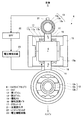
図2は下側トルクロッドアセンブリ(以下、単に「トルクロッドアセンブリ」ともいう。)6の概略平面図である。なお、図2のロッドは図1との関係では「ロッド11B」であるが、以下では単に「ロッド11」で説明する。
FIG. 2 is a schematic plan view of a lower torque rod assembly (hereinafter also simply referred to as “torque rod assembly”) 6. The rod in FIG. 2 is “
まず、2重防振の効果が得られるインシュレータは、本実施形態ではロッド11の両端に溶接により固定される一対のブッシュ12、13によって具現化されている。すなわち、棒状のロッド11の一端(図2で下端)に第1ブッシュ12(第1インシュレータ)を有する。第1ブッシュ12は円筒状の外筒12aと、外筒12aと同心の円筒状の内筒12bと、これら外筒12aと内筒12bとを連結する弾性体(防音材)12cとからなっている。内筒12bに対して図2で紙面に直交する向きに挿通されるボルト(図示しない)によって第1ブッシュ12はエンジン1に固定される。
First, the insulator capable of obtaining the double vibration isolation effect is embodied by a pair of
一方、ロッド11の他端(図2で上端)に第2ブッシュ13(第2インシュレータ)を有する。第2ブッシュ13も、第1ブッシュ12と同様に、円筒状の外筒13aと、外筒13aと同心の円筒状の内筒13bと、これら外筒13aと内筒13bとを連結する弾性体(防音材)13cとからなっている。内筒13bに対して図で紙面に直交する向きに挿通されるボルト(図示しない)によって小端部13は車体側部材2に固定される。
On the other hand, the other end (upper end in FIG. 2) of the
なお、実施形態は、第1ブッシュ12をエンジンに、第2ブッシュ13を車体側に固定する構成であるが、これに限らず、第1ブッシュ12を車体側に、第2ブッシュ13をエンジンに固定する構成としてもかまわない。また、下側トルクロッドアセンブリ6では、図2のように第1、第2のブッシュの内筒12b、13bに挿通される2つのボルトが平行に配置されるのに対して、図1に示される上側トルクロッドアセンブリ5では、第1、第2のブッシュの内筒に挿通される2つのボルト18、19が互いに直交する向きに配置されている。このように、下側トルクロッドアセンブリ6と上側トルクロッドアセンブリ5とでボルトの配置に多少の違いはあるが、機能としては両者で全く変わらない。
In the embodiment, the
図2に戻り、上記の弾性体(防音材)12c、13cとしては、ばねと減衰の機能を兼ね備えた部材であり、例えば弾性ゴムを用いる。 Returning to FIG. 2, the elastic bodies (soundproofing materials) 12c and 13c are members having both a spring and a damping function, and for example, elastic rubber is used.
本実施形態では、第1ブッシュ12と第2ブッシュ13とでは外筒、内筒の径を相違させる。すなわち、第2ブッシュ13の外筒13a、内筒13bの径を、対応する第1ブッシュ12の外筒12a、内筒12bの径よりも相対的に小さくすると共に、さらに、第2ブッシュ13の弾性体13cの剛性を、第1ブッシュ12の弾性体12cの剛性よりも相対的に大きくする。一対のブッシュ12、13の弾性体12c、13cの剛性を異ならせることで、2つの異なる周波数において2重防振に適したロッド軸方向のエンジン剛体共振とロッド剛体共振とを生じさせている。すなわち、図4に実線で示したように、第1ブッシュ12の弾性体12cの剛性から定まるロッド軸方向のエンジン剛体共振Aがほぼゼロに近い周波数f1[Hz]で生じ、第2ブッシュ13の弾性体13cの剛性から定まるロッド軸方向のロッド剛体共振Bが200Hzに近い周波数f2[Hz]で生じている。分かり易さのため、エンジン剛体共振とロッド剛体共振を極めて単純化したばねマス系に基づいて説明すれば、エンジン剛体共振Aは、エンジン質量と、第1ブッシュ弾性体12cの剛性(ばね定数)で決まり、ロッド剛体共振Bは、第1ブッシュ弾性体12cと第2ブッシュ弾性体13cの間の質量であるロッド11(および各ブッシュの外筒部分)の質量と、第2ブッシュ弾性体13cの剛性(ばね定数)で決まる。エンジン1(パワープラント)単体での曲げ、捩りの1次の共振周波数f3は、一般的な車両用エンジンでは280Hz〜350Hz程度なので、本実施形態のようにエンジン剛体共振Aをほぼゼロ(0Hz)とし、ロッド剛体共振Bを約200Hzとすれば、エンジン1の曲げ、捩りの共振振動の車体への伝達が、高周波数側(防振域内)で効果的に抑えられる(2重防振される)ことになる。以上より、エンジン剛体共振Aおよびロッド剛体共振Bが、エンジンの曲げ、捩りの共振周波数f3より小さな周波数となるように、第1ブッシュ弾性体12cの剛性(ばね定数)、および第1ブッシュ弾性体12cと第2ブッシュ弾性体13cの間の質量であるロッド11(および各ブッシュの外筒部分)の質量、第2ブッシュ弾性体13cの剛性(ばね定数)を定めれば良い。このように、エンジン剛体共振Aおよびロッド剛体共振Bを2つの異なる周波数で、つまり低周波域の周波数f1と、中周波数域の周波数f2との2箇所で生じさせてエンジン1から車体側に伝達される振動を防止する効果が得られるのが2重防振の効果である。
In the present embodiment, the diameters of the outer cylinder and the inner cylinder are different between the
なお、図4においては200Hz付近を中周波数域とし、これより周波数の低い側を低周波域、これより高い側を高周波域と定義する。この場合、エンジン1(パワープラント)の曲げ、捩りの共振周波数f3は図4において高周波数域にある。 In FIG. 4, the vicinity of 200 Hz is defined as the middle frequency range, the lower frequency side is defined as the low frequency range, and the higher frequency range is defined as the high frequency range. In this case, the resonance frequency f3 of bending and twisting of the engine 1 (power plant) is in a high frequency region in FIG.
次に、本発明で追加する振動低減要素を説明すると、これは、磁性を有する金属等からなる慣性マス15と、アクチュエータ17と、加速度センサ21(振動加速度検出手段)と、バンドパスフィルタ22と、電圧増幅回路23とから構成されている。
Next, the vibration reducing element added in the present invention will be described. This includes an
まず、ロッド11の周囲にロッド11と同軸で慣性マス15が設けられる。ロッド11の軸方向に見た慣性マス15の断面は、ロッド11の中心(重心)を中心にした点対称な形であると共に、慣性マス15の重心がロッド11の中心に一致している。慣性マス15は、図1にも示されているように角筒型で、慣性マス15のロッド軸方向の両端(図2で上下端)がそれぞれ弾性支持バネ16(支持部材)を介してロッド11に連結されている。弾性支持バネ16は、たとえば比較的小さな剛性を有する板バネである。慣性マス15の内壁15aはその一部が後述するアクチュエータ17の永久磁石17cに向けて凸設されている。
First, an
慣性マス15とロッド11との間の空間にアクチュエータ17が設けられる。アクチュエータ17は、角筒状のコア17aと、コイル17bと、永久磁石17cとを含むリニアタイプ(直線運動型)のアクチュエータで、慣性マス15をロッド11の軸方向に往復動するものである。
An
コイルの磁路を構成するコア17aは積層鋼鈑から構成されており、ロッド11に固設される。コア17aは、トルクロッドアセンブリの組立前には複数個の部材に分割されており、これら複数個の部材を接着剤で棒状のロッド11周囲に接着することにより、全体として角筒状のコア17aを形成している。コイル17bは、この角筒状のコア17aに巻装される。永久磁石17cは、コア17aの外周面に設けられる。
The
アクチュエータ17は、このような構成であるので、コイル17bと永久磁石17cとが発生する磁界によるリアクタンストルクによって慣性マス15をリニアに、つまり慣性マス15をロッド11の軸方向に往復動するように駆動することとなる。
Since the
ロッド11の略軸心の延長線上の第2ブッシュ13の先端(図2で上端)に、ロッド11の略軸心位置での軸方向の振動の加速度を、エンジン1からロッド11に伝達される振動の加速度として検出する加速度センサ21を取り付けてあり、加速度センサ21からのロッド軸方向加速度の信号をバンドパスフィルタ22を介して電圧増幅回路23に入力し、この電圧増幅回路23で増幅された信号をアクチュエータ17のコイル17bに印加する(電圧の制御を行なう)。電圧増幅回路23は例えばオペアンプから構成すればよい。
The acceleration of the vibration in the axial direction at the approximate axial center position of the
慣性マス15は比較的柔らかい板バネで支持され、例えば慣性マス15のロッドに対するロッド軸方向の共振は10Hzから100Hzまでの低い周波数で生じるものとする。例えば4気筒エンジンのアイドル回転速度2次の振動周波数は約20Hzであることから、慣性マス15の共振周波数を10Hzにすることができれば、エンジン1の運転条件によらず慣性マス15が共振するのを抑えることができる。一方、慣性マス15の共振周波数を10Hzといったこのような低周波数に設定しようとすると、慣性マス15が大きくなりすぎてそのような設定が困難な場合には、抑制しようとするロッド剛性共振B(実施形態では200Hz)の約1/2の周波数より低く設定しておけば、互いの共振周波数が十分に離れ、後述するような振動伝達の抑制が十分に行なわれる。また、加速度センサ21で検出した加速度信号をバンドパスフィルタ22に通すことによって、余分な周波数での制御を行なわないようにして、制御安定性を高めるとともに、余分な電力消費を抑えつつ狙いの周波数範囲での確実な伝達力の抑制を図ることができる。ロッド剛体共振Bに対する防振域は、図5に示したようにロッド剛体共振Bの共振周波数f2に対して所定値(≒1.4)を乗じて求まる周波数f5以上の周波数範囲であるので、バンドパスフィルタ22としては、慣性マス15のロッド軸方向の共振周波数(10Hzから100Hzまでの低い周波数)を含みこの共振周波数より、ロッド剛体共振Bに対する防振域の周波数範囲までの信号を通過するフィルタであって、防振域のうち制御が発散しない範囲の上限(例えば400Hzとする)までの信号を通過するフィルタを選定する。
The
そして、制御対象であるロッド11の減衰を増大する速度フィードバック制御が行われるように、バンドパスフィルタ22で通過している周波数帯において、加速度センサ21により検出した振動のロッド軸方向速度に略比例した力を逆符合とした力をアクチュエータ17から発生させる。これについてさらに説明すると、図14は電圧増幅回路23とアクチュエータ17とを機能的に表現したものである。加速度センサ21により検出されるロッド11のロッド軸方向加速度d2xr/dt2は電圧増幅回路23でのゲインGが乗算され、さらに逆符号とされるため、電圧増幅回路23からの出力は、−G・d2xr/dt2となる。この出力がアクチュエータ17に入力されると、アクチュエータ17のコイル17bが積分器として働くため、ロッド軸方向加速度d2xr/dt2は積分されてロッド11のロッド軸方向速度dxr/dtとなる。この結果、アクチュエータ17の発生する力Faは、dxr/dtに比例し、加速度の向きとは逆向きの力となる。つまり、制御対象であるロッド11の減衰を増大する速度フィードバック制御が行われる。
Then, in order to perform speed feedback control that increases the attenuation of the
図3は、2重防振の効果が得られる構成の物理モデルに対して、慣性マス15の質量miを備えるアクチュエータ17の発生力Faからなる本発明の振動低減要素を追加したモデルである。本発明では、ロッド剛体共振Bを抑制することを考えるため、エンジン剛体共振Aは無視する。図示のモデルよりロッド11についての運動方程式は、
(−mrω2+criω+kr)xr=Fe+Fa …(1)
ただし、mr :ロッド11の質量(両ブッシュの外筒質量を含む)、
xr :ロッド11の軸方向変位、
ω :角周波数、
kr :第2ブッシュ13の軸方向の剛性、
cr :第2ブッシュ13の軸方向の減衰、
i :虚数単位、
Fe:第1ブッシュ12を介したエンジンからの入力、
Fa:アクチュエータ17の発生力、
の式により与えることができる。また、ロッド11から車両側部材2への入力Ftは、
Ft=kr・xr+criω・xr …(2)
ただし、xr :ロッド11の軸方向変位、
ω :角周波数、
kr :第2ブッシュ13の軸方向の剛性、
cr :第2ブッシュ13の軸方向の減衰、
i :虚数単位、
の式により与えられる。
3, the physical model of the effect of 2 vibration proofing is obtained, is a model that adds a vibration reducing element of the present invention comprising a generating force Fa of the
(−m r ω 2 + c r iω + k r ) x r = Fe + Fa (1)
Where m r : the mass of the rod 11 (including the outer cylinder mass of both bushes),
xr : axial displacement of the
ω: angular frequency,
k r : rigidity of the
cr : axial attenuation of the
i: imaginary unit,
Fe: input from the engine via the
Fa: Generating force of the
It can be given by the following formula. The input Ft from the
Ft = k r · x r + c r iω · x r (2)
Where xr : axial displacement of the
ω: angular frequency,
k r : rigidity of the
cr : axial attenuation of the
i: imaginary unit,
Is given by
本発明では、アクチュエータ17の発生力Faを、
Fa=−Giωxr …(3)
ただし、xr :ロッド11の軸方向変位、
ω :角周波数、
i :虚数単位、
G :ゲイン(速度フィードバックゲイン)、
の式で与える。すなわち、(3)式によりロッド11の軸方向変位krを一階微分した値であるロッド軸方向速度に比例した力を発生させる。このとき、上記(1)式は、
(−mrω2+{cr+G}iω+kr)xr=Fe …(4)
の式のように変形される。(4)式より、ロッド11の減衰項をcrからcr+Gへと増大できることがわかる((4)式の左辺第2項参照)。
In the present invention, the generated force Fa of the
Fa = −Giωx r (3)
Where xr : axial displacement of the
ω: angular frequency,
i: imaginary unit,
G: Gain (speed feedback gain),
Is given by That is, to generate a force proportional to the rod axis direction velocity is a value obtained by differentiating first order axial displacement k r of the
(−m r ω 2 + {c r + G} iω + k r ) x r = Fe (4)
It is transformed as (4) from the equation, it can be seen that the attenuation term of the
一般的に、第2ブッシュ13のロッド軸方向の減衰(cr)そのものを増大させると、図4に破線で示したように、ロッド剛体共振B付近の周波数での伝達力が小さくなりロッド剛体共振Bそのものは抑制されるものの、ロッド剛体共振Bの共振周波数f2以上の高周波域においては、第2ブッシュ13のロッド軸方向の減衰(cr)を増大させる前より却って伝達力が大きくなり、高周波域側での車体側部材2への伝達特性が悪化してしまうことが知られている。
In general, when the damping (c r ) itself of the
このメカニズムを、車体側部材2への伝達特性に着目して説明すると、2重防振の効果が得られる構成による車体側部材2への伝達特性は、上記(1)式(ただし、アクチュエータ発生力Fa=0)、(2)式より、
Ft/Fe=(kr+criω)/(−mrω2+criω+kr)…(5)
の式で表される。ロッド剛体共振B付近の周波数では、mrω2の絶対値とkrの絶対値が近づき−mrω2とkrが相殺し合うため、(5)式右辺分母の減衰(cr)の値で車体側部材2への伝達特性が決定される。つまり、ロッド剛体共振B付近の周波数で伝達力を小さくしたい場合には、減衰(cr)の値を大きくする。その一方で、(5)式右辺の分子にも減衰(cr)が含まれることから、ロッド剛体共振Bの共振周波数f2を超える周波数域でも、車体側部材2への伝達特性は減衰の値に影響を受ける。このように、(5)式右辺の分子は、第2ブッシュ13のロッド軸方向の剛性(kr)と、第2ブッシュ13のロッド軸方向の減衰(cr)とで決められており、通常の2重防振が得られる程度の減衰では、剛性(kr)の値が支配的であるが、ロッド剛体共振Bを抑制するほどの減衰を、分母の減衰(cr)を大きくして与えると、この分母の減衰(cr)に連動して分子の減衰(cr)が大きくなる。その結果、図4に破線で示したようにロッド剛体共振Bの共振周波数f2を超える周波数域で車体側部材2への伝達力が却って大きくなり、高周波域側での車体側部材2への伝達特性を悪化させてしまうのである。
This mechanism will be described by paying attention to the transmission characteristic to the vehicle
Ft / Fe = (k r + c r iω) / (− m r ω 2 + c r iω + k r ) (5)
It is expressed by the following formula. At frequencies near the rod rigid body resonance B, since the absolute value of m r omega 2 of the absolute value and k r are cancel -m r omega 2 and k r approaches, (5) the attenuation of the right side of the equation the denominator (c r) The transmission characteristic to the vehicle
これに対して本実施形態のように、2重防振の効果が得られる構成とした上で、慣性マス15、アクチュエータ17、加速度センサ21を追加し、バンドパスフィルタ22及び電圧増幅回路23からなる制御手段で速度フィードバック制御を行わせることによって、ロッド11軸方向の減衰を増大した場合には、上記(2)式、(4)式を用いて、車体側部材2への伝達特性が、
Ft/Fe=(kr+criω)/(−mrω2+{cr+G}iω+kr)
…(6)
の式で表されることになる。(6)式では、ロッド剛体共振Bを抑制する(6)式右辺分母の減衰には、制御効果としての減衰の増大(cr+G)が現れる一方で、(6)式右辺分子については、第2ブッシュ13のロッド軸方向の剛性(kr)と、第2ブッシュ13のロッド軸方向の減衰(cr)のみとなる、つまり(6)式右辺分子の減衰(cr)は変化しないため、(6)式右辺分母の減衰の増大の影響を受けることがない。このようにして、第1ブッシュ12を介したエンジン1からの入力Feにのみ影響するよう、言わば見かけ上の減衰を増大させて、伝達力を低下させる。したがって、(6)式によれば、図5に一点鎖線で示したように、ロッド剛体共振Bの抑制と、ロッド剛体共振Bの共振周波数f2を超える高周波数域での防振特性(2重防振)とを両立できる。第2ブッシュ13のロッド軸方向の減衰(cr)は、通常の2重防振(高周波数域での十分な伝達力の抑制)が得られる程度の減衰とする。
On the other hand, as in the present embodiment, after the double vibration isolation effect is obtained, an
Ft / Fe = (k r + c r iω) / (− m r ω 2 + {c r + G} iω + k r )
... (6)
It will be expressed by the following formula. In the expression (6), the attenuation of the right-hand side denominator of the expression (6) that suppresses the rod rigid body resonance B shows an increase in attenuation (c r + G) as a control effect. On the other hand, Only the rigidity ( kr ) of the
また、バンドパスフィルタ22で通過された周波数範囲において、ロッド剛体共振Bの減衰が向上できている。このようにゲインGは、ロッド剛体共振Bの周波数付近の伝達力を十分に低下させる、言い換えるとロッド剛体共振Bによる伝達力増大が発生しなくなる程度の値に設定される。ここで、慣性マス15の実際の取付点は、図2においてはC点、D点の2箇所であるが、図3に示したモデルでは、C点とD点とを平均した位置であるE点を「慣性マス15の取り付け点」として扱っている。
Further, the attenuation of the rod rigid body resonance B can be improved in the frequency range passed by the
図6は第1ブッシュ12にエンジン剛体共振Aが生じているときの第1ブッシュ12の外筒12aの変形を拡大して示している。エンジン剛体共振Aの共振周波数f1は、図4、図5にも示したようにゼロに近く十分に高い周波数でないため、図6に示す第1ブッシュの外筒12aの大きな変形の影響を受けてロッド11の振動と第1ブッシュの外筒12aの振動とが違ったものとなり得る。従って、ロッド11の略軸心の延長線上の第1ブッシュ12の先端に加速度センサ21を取り付けたのでは、この第1ブッシュ12の外筒12aの大きな変形の影響を受けて制御が発散してしまうことが考えられたため、本実施形態では、第1ブッシュの外筒12aよりも共振時の変形量が小さな第2ブッシュの外筒13a(剛性が相対的に大きい側の外筒)のほうに加速度センサ21を配置している。
FIG. 6 is an enlarged view of the deformation of the
図7はエンジン回転速度が3000rpmの条件でアクセルペダルを一杯まで踏み込む加速を行ったときの200Hzから1000Hzまでの車内音の合計の騒音レベルを示している。本実施形態によれば、2重防振の効果が得られる構成だけの場合より騒音レベルを低下させることができていることが解る。 FIG. 7 shows the total noise level of the in-vehicle sound from 200 Hz to 1000 Hz when acceleration is performed by depressing the accelerator pedal to the full when the engine speed is 3000 rpm. According to the present embodiment, it can be seen that the noise level can be reduced as compared with the case of only the configuration capable of obtaining the double vibration isolation effect.
以上は、主にエンジン1から車体側部材2に伝達される中周波域から高周波域にかけての振動低減を主に考えたものであった。次には、この中周波域から高周波域にかけての振動低減に加えて、さらにエンジン1から車体側部材2に伝達される低周波域での振動低減を考える。低周波域でエンジン1から車体側部材2に伝達される振動を低減させるとは、こもり音を抑制することである。こもり音とは、エンジン回転の基本次数によるエンジン振動に基づく音のことで、4気筒エンジンの基本次数は回転2次、6気筒エンジンの基本次数は回転3次である。こもり音に対しては次の対策を講じる。たとえば直列4気筒エンジンでは、エンジン回転速度ごとに図8に示したようなマップを用意しておき、そのときのエンジン回転速度からこのマップを検索して振幅の大きさと位相を求め、これらを用いて、
F=Asin(2θ+B) …(7)
ただし、A:振幅の大きさ、
B:位相、
θ:クランク角、
の式により、そのときのエンジン回転速度に最適な加振力の大きさFを設定し、上記(3)式のアクチュエータ17の発生力Faにこの(7)式の加振力Fを加えた値を改めてアクチュエータ17の発生力Faとする。
The above has mainly considered reduction of vibration from the middle frequency range to the high frequency range transmitted from the
F = Asin (2θ + B) (7)
Where A: magnitude of amplitude,
B: Phase,
θ: crank angle,
The magnitude F of the excitation force that is optimal for the engine speed at that time is set by the following equation, and the excitation force F of the equation (7) is added to the generated force Fa of the
このように(7)式の加振力Fをアクチュエータ17の発生力Faに追加することで、図9に示したように、直列4気筒エンジンにおいてエンジン回転速度が低い場合に、(7)式の加振力Fをアクチュエータ17の発生力Faに追加しない比較形態に比べてこもり音(車内音)を低減できている。
Thus, by adding the excitation force F of equation (7) to the generated force Fa of the
このようにして、本実施形態の振動低減装置によれば、低周波域でのこもり音から、加速時の騒音までを大幅に低減することができることになった。 In this way, according to the vibration reducing apparatus of the present embodiment, it is possible to greatly reduce the noise from the humming noise in the low frequency range to the noise during acceleration.
ここで、本実施形態の作用効果を説明する。 Here, the effect of this embodiment is demonstrated.
本実施形態(請求項1に記載の発明)によれば、エンジン1(エンジン側)に取り付けられる第1ブッシュ12(第1インシュレータ)と、車体側部材2(車体側)に取り付けられる第2ブッシュ13(第2インシュレータ)と、これら一対のブッシュ12、13を連結するロッド11と、このロッド11に支持された慣性マス15と、この慣性マス15をロッド11の軸方向に往復動させるアクチュエータ17と、このアクチュエータ17を制御する制御手段(21、22、23)と、を備えた、エンジン1から車体に伝達される振動を低減する振動低減装置において、ロッド剛体共振Bの周波数f2をエンジン1の曲げ・捩り共振周波数f3より低く設定し、ロッド11の軸方向変位xrの速度に比例した力Fa(=−Giωxr)をアクチュエータ17に発生させるので、第2ブッシュ13(第2インシュレータ)の弾性体13cの減衰特性を維持したままでロッド11の減衰を増大することが可能となり、ロッド軸方向のロッド剛体共振Bの抑制と、2重防振とを両立できる。
According to this embodiment (the invention described in claim 1), the first bush 12 (first insulator) attached to the engine 1 (engine side) and the second bush attached to the vehicle body side member 2 (vehicle body side). 13 (second insulator), a
本実施形態(請求項2に記載の発明)によれば、ロッド11の軸方向変位の加速度信号(または速度信号)を、ロッド剛体共振Bの周波数f2を含む所定の周波数範囲の信号を通過させるフィルタ22を通過させ、フィルタ22通過後の加速度信号(または速度信号)に基づいてアクチュエータ17を制御するので、余分な周波数での制御を行なわないようにして、制御安定性を高めるとともに、余分な電力消費を抑えつつロッド剛体共振周波数f2付近の伝達力の抑制を図ることができる。
According to this embodiment (the invention described in claim 2), the acceleration signal (or velocity signal) of the axial displacement of the
本実施形態(請求項3に記載の発明)によれば、所定の周波数範囲は、ロッド剛体共振Bの周波数f2より高周波数側にある防振域(図5に示す周波数f5以上の周波数範囲)の周波数を含むので、ロッド剛体共振周波数f2から防振域に至る周波数範囲で伝達力を抑制させることができる。 According to the present embodiment (the invention described in claim 3), the predetermined frequency range is a vibration isolation region on the higher frequency side than the frequency f2 of the rod rigid body resonance B (frequency range equal to or higher than the frequency f5 shown in FIG. 5). Therefore, the transmission force can be suppressed in the frequency range from the rod rigid resonance frequency f2 to the vibration isolation region.
本実施形態(請求項4に記載の発明)によれば、所定の周波数範囲は、ロッド剛体共振Bの周波数f2より低周波数側にある慣性マス15の共振周波数を含むので、高い周波数の局所的に変形する共振を制御しないため、制御の安定性を向上できる。
According to the present embodiment (the invention described in claim 4), the predetermined frequency range includes the resonance frequency of the
本実施形態(請求項5に記載の発明)によれば、慣性マス15はロッド11に弾性支持され、慣性マス15の共振周波数がロッド剛体共振周波数f2の1/2以下であるので、慣性マス15の共振周波数をロッド剛体共振周波数f2から十分に離すことができる。
According to this embodiment (the invention described in claim 5), the
本実施形態(請求項6に記載の発明)によれば、第1ブッシュ12(第1インシュレータ)および第2ブッシュ13(第2インシュレータ)は、ロッド11に連結した外筒12a、13aと、外筒12a、13aの内側に設けられた内筒12b、13bと、内筒12b、13bと外筒12a、13aとの間に介装された弾性体12c、13cとからなり、ロッド剛体共振Bの周波数f2がエンジンの曲げ・捩り共振周波数f3より低くなるように、ロッド11と第1ブッシュ12の外筒12aおよび第2ブッシュ13の外筒13aの合計質量と、第2ブッシュ13の弾性体13cの減衰とが、設定されているので、内外筒ブッシュ構造において2重防振に適したロッド剛体共振周波数f2を設定できる。
According to the present embodiment (the invention described in claim 6), the first bush 12 (first insulator) and the second bush 13 (second insulator) are connected to the
本実施形態(請求項7に記載の発明)によれば、第1ブッシュ12(第1インシュレータ)の外筒12aと第2ブッシュ13(第2インシュレータ)の外筒13aのうち、剛性が相対的に大きい側の外筒13aのロッド11の略軸心位置に取り付けられ、ロッド11の軸方向変位の加速度を検出する加速度センサ21を備え、アクチュエータ17は、ロッド11に固設されるコア17aと、このコア17aに巻装されるコイル17bと、コア17aの外周面に設けられる永久磁石17cとを含む直線運動型のアクチュエータであり、制御手段は、加速度センサ21から出力される加速度信号を増幅し、この増幅した信号をコイル17bに印加する電圧増幅回路23を有するので、剛性が相対的に大きい側の弾性体13cを有する第2ブッシュ13は、制御したい周波数帯域に固有モードを持たないことから、制御の安定性を向上でき、ロッド11の減衰を増やす制御効果を増すことができる。ロッド11の動きに良く追従した加速度信号に基づいてコイル電圧印加を行なえる。
According to the present embodiment (the invention described in claim 7), the rigidity is relatively between the
本実施形態(請求項11に記載の発明)によれば、エンジン1はペンデュラム方式でマウントされているので、主に入力が入る伝達経路で制御がきるため、大きな振動・騒音低減効果を得ることができる。
According to the present embodiment (the invention described in claim 11), since the
図10は第2実施形態のトルクロッドアセンブリ6で、このうち図10(a)はトルクロッドアセンブリ6の斜視図を、図10(b)は図10(a)の一部断面図を示している。
FIG. 10 shows a
ただし、図10(a)、図10(b)において、右側に示される第1ブッシュ12は外筒12aのみを示し、内筒12b、インシュレータ12cを省略して示していない。同様にして左側に示される第2ブッシュ13としては外筒13aのみを示し、内筒13b、インシュレータ13cを省略して示していない。また、アクチュエータ17についても角柱状のコア17aのみを示し、コイル17b、永久磁石17cを省略して示していない。
However, in FIGS. 10A and 10B, the
図2に示した第1実施形態では、角筒型のコア17aは組立前には複数の部材に分割されており、全体として角筒状となるように接着剤によって棒状のロッド11に固設したが、接着剤の熱劣化によってコア17aがロッド11から剥がれ落ちてしまうことが考えられる。そこで、第2実施形態は、接着剤によらないでコア17aをロッド11に固設するものである。
In the first embodiment shown in FIG. 2, the rectangular tube-shaped
図10(a)、図10(b)はトルクロッドアセンブリ6の組立後の状態を示しており、組立前には、第1ブッシュ12、第2ブッシュ13はロッド11とは別部材として構成されている。ロッド11は、大径部31と小径部32とから構成され、ロッド小径部32の外周には、ロッド小径部32の端部(図で左側)よりロッド大径部31に向けて所定長さの雄ねじ34が設けられている。
FIGS. 10A and 10B show a state after the
一方、コア17aは積層鋼鈑を用い全体として角柱状に形成されると共にコア17aの軸心位置(重心位置)に、ロッド小径部32の外径とロッド大径部31の外径との間の径を有する貫通孔35が穿設されている。
On the other hand, the
このため、ロッド小径部32をこの貫通孔35に挿通させ、コア17aをロッド小径部32とロッド大径部31の段差33に押しつけた後に、雄ねじ34と噛み合うナット36で締め付けることでコア17aをロッド11に固定する。このようにして、ナット36の弾性力でコア17aをロッド11に固定した後で、第2ブッシュ13の外筒13aとロッド小径部32の端部とを、第1ブッシュ12の外筒12aとロッド大径部31の端部とをそれぞれ溶接により固定する。
For this reason, the rod
このように第2実施形態(請求項10に記載の発明)によれば、ロッド11を、大径部31と、外周に雄ねじ34を有する小径部32とから構成する一方で、コア17aを角柱状に形成すると共にこの角柱状のコア17aに大径部31の径と小径部32の径との間の径を有する孔35を貫通しておき、小径部32をこの貫通孔35に挿通させ、コア17aを小径部32と大径部31の段差33に押しつけた後に、雄ねじ34と噛み合うナット36で締め付けることでコア17aをロッド11に固定し、その後で第2ブッシュ13の外筒13aと小径部32の端部とを、また第1ブッシュ12の外筒12aと大径部31の端部とをそれぞれ溶接により固定するので、
コア17aをロッド軸方向に直交する方向に長くしても、ロッド11から外れることがなく、かつ接着剤でコア17aをロッド11に固設する場合よりも高い耐熱性を得ることができる。
Thus, according to the second embodiment (the invention described in claim 10), the
Even if the
図11は第3実施形態のトルクロッドアセンブリ6の概略平面図である。第1実施形態の図2と同一部分には同一番号を付している。
FIG. 11 is a schematic plan view of the
第3実施形態では、図2に示す加速度センサ21、バンドパスフィルタ22、電圧増幅回路23に代えて、主にマイクロコンピュータ、メモリからなるコントローラ41を有するものである。2重防振の効果が得られる構成とした上で慣性マス15とアクチュエータ17とを追加した構成は第1実施形態と同様である。
In the third embodiment, instead of the
第3実施形態では、振動低減装置を、図12に示したように慣性マス15の取り付け点に強制変位を受ける1自由度振動系としてモデル化している。この1自由度振動系のモデルにおいて、慣性マス15とロッド11との各運動方程式は、
mid2x/dt2+cidx/dt+kix=u+w …(8)
cidx0/dt+kix0=w …(9)
ただし、mi :慣性マス15の質量、
ci :慣性マス15の支持部材(16)のロッド軸方向の減衰、
ki :慣性マス15の支持部材(16)のロッド軸方向の剛性、
x :慣性マス15のロッド軸方向変位、
dx/dt :慣性マス15のロッド軸方向速度、
d2x/dt2:慣性マス15のロッド軸方向加速度、
x0 :ロッド11の軸方向変位、
dx0/dt :ロッド11の軸方向速度、
u :アクチュエータ17の制御力、
w :外乱、
の式で表すことができる。ここで、慣性マス15の取り付け点とは、図11に示したようにE点のことである。
In the third embodiment, the vibration reducing device is modeled as a one-degree-of-freedom vibration system that undergoes forced displacement at the attachment point of the
m i d 2 x / dt 2 + c i dx / dt + k i x = u + w ... (8)
c i dx 0 / dt + k i x 0 = w (9)
Where m i is the mass of the
c i : damping in the rod axis direction of the support member (16) of the
k i : rigidity in the rod axis direction of the support member (16) of the
x: rod axial displacement of
dx / dt: rod axial velocity of the
d 2 x / dt 2 : acceleration of the
x 0 : axial displacement of the
dx 0 / dt: axial speed of the
u: control force of
w: disturbance,
It can be expressed by the following formula. Here, the attachment point of the
さて、上記(8)式、(9)式を、慣性マス15のロッド軸方向加速度d2x/dt2を出力として状態空間表現に変換すると、
Now, when the above equations (8) and (9) are converted into a state space expression using the rod axis direction acceleration d 2 x / dt 2 of the

(10)式に基づけば、慣性マス15のロッド軸方向加速度d2x/dt2とアクチュエータ17の制御力uより、慣性マス15のロッド軸方向速度dx/dt、慣性マス15のロッド軸方向変位x、慣性マス15の取り付け点のロッド軸方向変位x0の3つを推定するオブザーバを作ることができ、さらに、推定された慣性マス15の取り付け点のロッド軸方向変位x0を一階微分することにより慣性マス15の取り付け点のロッド軸方向速度dx0/dtを推定することができる。このようにして、慣性マス15ならびにロッド11のロッド軸方向変位の状態量がオブザーバによって推定される。
Based on the equation (10), the rod mass direction velocity dx / dt of the
第3実施形態では、慣性マス15のロッド軸方向加速度d2x/dt2を検出し、かつ
uv=−G1dx0/dt …(11)
の式により、つまり慣性マス15の取り付け点のロッド軸方向速度dx0/dtにゲインG1を乗じ、逆符号とした力uvを制御対象であるロッド11に入力する。このとき、演算に用いるロッド軸方向速度として、第1実施形態と同様のフィルタを通過させた後のロッド軸方向速度を用いても良い。すなわち、慣性マス15のロッド軸方向の共振周波数を含み、この共振周波数より、ロッド剛体共振Bに対する防振域の周波数範囲までの信号を通過するフィルタであって、防振域のうち制御が発散しない範囲の上限までの信号を通過するフィルタを通過したロッド軸方向速度dx0/dtを用いることができる。これにより、余分な周波数での制御を行なわないようにして、制御安定性を高めるとともに、余分な電力消費を抑えつつ狙いの周波数範囲での確実な伝達力の抑制を図ることができる。
In the third embodiment, the rod axis direction acceleration d 2 x / dt 2 of the
That is, the rod axial velocity dx 0 / dt at the attachment point of the
ここで、制御対象であるロッド11に入力される力uvに対して、アクチュエータ17の制御力uは、
u=ci(dx/dt−dx0/dt)+ki(x−x0)−uv …(12)
の式で表される。
Here, against the force u v inputted to the
u = c i (dx / dt−dx 0 / dt) + k i (x−x 0 ) −u v (12)
It is expressed by the following formula.
慣性マス15のロッド軸方向加速度d2x/dt2は、アクチュエータ17の逆起電力から検出される。従って、図13のように、コントローラ41を、オブザーバ42と、2つの積分器43、44と、減算器45とから制御系を構成する。すなわち、オブザーバ42により推定した慣性マス15の取り付け点のロッド軸方向速度dx0/dtから積分器44で上記(11)式によりロッド11に入力する力uvを決定する。また、オブザーバ42により推定した慣性マス15のロッド軸方向速度dx/dt、慣性マス15の取り付け点におけるロッド11の軸方向速度dx0/dt、慣性マス15のロッド軸方向変位x、慣性マス15の取り付け点におけるロッド11の軸方向変位x0の4つを要素とする列ベクトルと、ci、−ci、ki、−kiの4つを要素とする行ベクトルとを積分器43で乗算してスカラーとする。そして、減算器45でこの求めたスカラーから上記のロッド入力uvを差し引くことで、つまり上記(12)式により制御力uを決定し、この制御力uに応じた電流をコイル17bに印加することにより、制御力uをアクチュエータ17から発生させる。
The rod axis direction acceleration d 2 x / dt 2 of the
第3実施形態は、図2に示される第1実施形態と比較して、加速度センサ21を設けていない。また、第3実施形態は、オブザーバ42を用い、ロッド軸方向速度dx0/dtにゲインG1を乗じ、逆符号とした力uvを制御対象であるロッド11に入力しているため、第1実施形態のような形態で速度フィードバックを行うものでない。このように、第3実施形態の制御手段の構成は図13に示した通りであり、バンドパスフィルタ22及び電圧増幅回路23からなる第1実施形態の制御手段の構成と異なるのであるが、コントローラ41が慣性マス15のロッド軸方向加速度d2x/dt2に基づいて制御力uを決定し、アクチュエータ17を駆動することによりこの制御力uを発生させるので、第1実施形態の図5に一点鎖線で示した第1実施形態(本発明)の効果と等しい効果が得られ、その結果、図7に示した第1実施形態の効果と等しい加速時の騒音低減効果が得られる。なお、コイル17bの制御を、速度に基づく制御量(速度にゲインを掛けて求めた制御量)で行なう場合、電流を制御することになる。
In the third embodiment, the
第3実施形態(請求項8に記載の発明)によれば、制御手段は、慣性マス15のロッド軸方向加速度d2x/dt2とアクチュエータ17の制御力uとに基づいて、少なくともロッドのロッド軸方向変位の速度dx0/dtを含む、慣性マス15ならびにロッド11のロッド軸方向変位の状態量を推定するオブザーバ42と、オブザーバ42から出力される前記速度信号(dx0/dt)にゲインG1を乗じ、逆符号とした力をロッド入力uvとして生成するロッド入力生成手段(44)と、を有するとともに、オブザーバ42により推定される慣性マス15ならびにロッド11のロッド軸方向変位の状態量と、慣性マス15の支持部材のロッド軸方向の減衰ciと、慣性マス15の支持部材のロッド軸方向の剛性kiと、ロッド入力uvとに基づいてアクチュエータ17の制御力uを算出するので、ロッド11の加速度センサ21を用いることなく請求項1の効果を得ることができる。すなわち、第2ブッシュ13(第2インシュレータ)の弾性体13cの減衰特性を維持したままでロッド11の減衰を増大することが可能となり、ロッド軸方向のロッド剛体共振Bの抑制と、2重防振とを両立できる。
According to the third embodiment (the invention described in claim 8), the control means is based on the rod axial acceleration d 2 x / dt 2 of the
第3実施形態(請求項9に記載の発明)によれば、慣性マス15のロッド軸方向加速度d2x/dt2をアクチュエータ17の逆起電力から検出するので、加速度センサ21を取り付ける必要がなく、コストを低減できる。
According to the third embodiment (the invention described in claim 9), since the rod axis direction acceleration d 2 x / dt 2 of the
5、6 トルクロッドアセンブリ
11 ロッド
12 第1ブッシュ(第1インシュレータ)
13 第2ブッシュ(第2インシュレータ)
15 慣性マス
17 アクチュエータ
21 加速度センサ(振動加速度検出手段)
22 バンドパスフィルタ
23 電圧増幅回路
41 コントローラ
42 オブザーバ
44 積分器(ロッド入力生成手段)
5, 6
13 Second bush (second insulator)
15
22 Band-
Claims (11)
車体側に取り付けられる第2インシュレータと、
これら一対のインシュレータを連結するロッドと、
このロッドに支持された慣性マスと、
この慣性マスを前記ロッドの軸方向に往復動させるアクチュエータと、
このアクチュエータを制御する制御手段と、
を備えた、エンジンから車体に伝達される振動を低減する振動低減装置において、
ロッド剛体共振の周波数を前記エンジンの曲げ・捩り共振周波数より低く設定し、
前記ロッドの軸方向変位の速度に比例した力を前記アクチュエータに発生させる
ことを特徴とする振動低減装置。 A first insulator attached to the engine side;
A second insulator attached to the vehicle body side;
A rod connecting these pair of insulators;
An inertial mass supported by this rod,
An actuator for reciprocating the inertial mass in the axial direction of the rod;
Control means for controlling the actuator;
In a vibration reduction device that reduces vibration transmitted from the engine to the vehicle body,
The frequency of the rod rigid body resonance is set lower than the bending / torsional resonance frequency of the engine,
A vibration reducing apparatus that causes the actuator to generate a force proportional to the speed of axial displacement of the rod.
前記ロッド剛体共振の周波数が前記エンジンの曲げ・捩り共振周波数より低くなるように、前記ロッドと前記第1インシュレータの外筒および前記第2インシュレータの外筒の合計質量と、前記第2インシュレータの弾性体の減衰とが、設定されていることを特徴とする請求項1から5までのいずれか一つに記載の振動低減装置。 The first insulator and the second insulator are composed of an outer cylinder connected to the rod, an inner cylinder provided inside the outer cylinder, and an elastic body interposed between the inner cylinder and the outer cylinder. Become
The total mass of the rod, the outer cylinder of the first insulator and the outer cylinder of the second insulator, and the elasticity of the second insulator so that the frequency of the rod rigid body resonance is lower than the bending / torsional resonance frequency of the engine. The vibration reduction apparatus according to any one of claims 1 to 5, wherein damping of the body is set.
前記アクチュエータは、前記ロッドに固設されるコアと、このコアに巻装されるコイルと、コアの外周面に設けられる永久磁石とを含む直線運動型のアクチュエータであり、
前記制御手段は、前記加速度センサから出力される加速度信号を増幅し、この増幅した信号を前記コイルに印加する電圧増幅回路を有することを特徴とする請求項6に記載の振動低減装置。 Of the outer cylinder of the first insulator and the outer cylinder of the second insulator, the outer cylinder on the side having relatively large rigidity is attached to the approximate axial center position of the rod, and the acceleration of the axial displacement of the rod is detected. An acceleration sensor
The actuator is a linear motion type actuator including a core fixed to the rod, a coil wound around the core, and a permanent magnet provided on an outer peripheral surface of the core,
The vibration reducing apparatus according to claim 6, wherein the control unit includes a voltage amplification circuit that amplifies an acceleration signal output from the acceleration sensor and applies the amplified signal to the coil.
前記慣性マスのロッド軸方向加速度と前記アクチュエータの制御力とに基づいて、少なくとも前記ロッドのロッド軸方向変位の速度を含む、前記慣性マスならびに前記ロッドのロッド軸方向変位の状態量を推定するオブザーバと、
このオブザーバから出力される前記速度信号にゲインを乗じ、逆符号とした力をロッド入力として生成するロッド入力生成手段と、
を有するとともに、
前記オブザーバにより推定される慣性マスならびにロッドのロッド軸方向変位の状態量と、前記慣性マスの支持部材のロッド軸方向の減衰と、前記慣性マスの支持部材のロッド軸方向の剛性と、前記ロッド入力とに基づいて前記アクチュエータの制御力を算出することを特徴とする請求項1から6までのいずれか一つに記載の振動低減装置。 The control means includes
An observer for estimating the inertia mass and the state quantity of the rod axial displacement of the rod including at least the speed of the rod axial displacement of the rod based on the rod axial acceleration of the inertia mass and the control force of the actuator. When,
A rod input generating means for multiplying the speed signal output from the observer by a gain and generating a force having an opposite sign as a rod input;
And having
The inertia mass estimated by the observer and the amount of rod axial displacement of the rod, the damping of the inertia mass support member in the rod axis direction, the rigidity of the inertia mass support member in the rod axis direction, and the rod The vibration reducing device according to claim 1, wherein a control force of the actuator is calculated based on an input.
小径部をこの貫通孔に挿通させ、コアを小径部と大径部の段差に押しつけた後に、雄ねじと噛み合うナットで締め付けることでコアをロッドに固定し、
その後で第2ブッシュと小径部の端部とを、また第1ブッシュと大径部の端部とをそれぞれ溶接により固定することを特徴とする請求項1から9までのいずれか一つに記載の振動低減装置。 The rod is composed of a large-diameter portion and a small-diameter portion having a male screw on the outer periphery, while the core is formed in a prismatic shape and the diameter of the large-diameter portion and the diameter of the small-diameter portion are formed in the prismatic core. Through a hole with a diameter between,
After inserting the small diameter part through this through hole, pressing the core against the step between the small diameter part and the large diameter part, the core is fixed to the rod by tightening with the nut that meshes with the male screw,
After that, the second bush and the end of the small diameter portion are fixed by welding, and the first bush and the end of the large diameter portion are fixed by welding, respectively. Vibration reduction device.
Priority Applications (5)
| Application Number | Priority Date | Filing Date | Title |
|---|---|---|---|
| JP2009157563A JP5278202B2 (en) | 2009-07-02 | 2009-07-02 | Vibration reduction device |
| EP10793969.6A EP2450593B1 (en) | 2009-07-02 | 2010-06-02 | Vibration reducing device |
| CN201080029902.8A CN102472359B (en) | 2009-07-02 | 2010-06-02 | Vibration reducing device |
| PCT/JP2010/059727 WO2011001799A1 (en) | 2009-07-02 | 2010-06-02 | Vibration reducing device |
| US13/380,254 US8827250B2 (en) | 2009-07-02 | 2010-06-02 | Vibration reduction device |
Applications Claiming Priority (1)
| Application Number | Priority Date | Filing Date | Title |
|---|---|---|---|
| JP2009157563A JP5278202B2 (en) | 2009-07-02 | 2009-07-02 | Vibration reduction device |
Publications (2)
| Publication Number | Publication Date |
|---|---|
| JP2011012757A JP2011012757A (en) | 2011-01-20 |
| JP5278202B2 true JP5278202B2 (en) | 2013-09-04 |
Family
ID=43410879
Family Applications (1)
| Application Number | Title | Priority Date | Filing Date |
|---|---|---|---|
| JP2009157563A Active JP5278202B2 (en) | 2009-07-02 | 2009-07-02 | Vibration reduction device |
Country Status (5)
| Country | Link |
|---|---|
| US (1) | US8827250B2 (en) |
| EP (1) | EP2450593B1 (en) |
| JP (1) | JP5278202B2 (en) |
| CN (1) | CN102472359B (en) |
| WO (1) | WO2011001799A1 (en) |
Families Citing this family (25)
| Publication number | Priority date | Publication date | Assignee | Title |
|---|---|---|---|---|
| WO2012026111A1 (en) * | 2010-08-23 | 2012-03-01 | 株式会社ブリヂストン | Torque rod and engine mount system using same |
| WO2012053091A1 (en) * | 2010-10-21 | 2012-04-26 | トヨタ自動車株式会社 | Tuned mass damper |
| JP5693384B2 (en) * | 2011-06-06 | 2015-04-01 | 株式会社ブリヂストン | Active control torque rod |
| JP5779033B2 (en) | 2011-07-29 | 2015-09-16 | 日産自動車株式会社 | Vibration isolator for vehicle |
| JP5834595B2 (en) * | 2011-07-29 | 2015-12-24 | 日産自動車株式会社 | Vibration isolator for vehicle |
| JP5861302B2 (en) * | 2011-07-29 | 2016-02-16 | 日産自動車株式会社 | Vibration isolator for vehicle |
| EP2574819B1 (en) * | 2011-09-30 | 2014-04-23 | Siemens Aktiengesellschaft | Speed-proportional active oscillation attenuator |
| JP5884441B2 (en) * | 2011-11-25 | 2016-03-15 | トヨタ自動車株式会社 | Support structure for vehicle torque rod and power unit |
| JP5911713B2 (en) * | 2011-12-06 | 2016-04-27 | 株式会社ブリヂストン | Vibration isolator |
| CN104136799B (en) * | 2012-02-24 | 2015-12-02 | 本田技研工业株式会社 | Active vibration reduces device |
| JP5969219B2 (en) * | 2012-02-28 | 2016-08-17 | 日産自動車株式会社 | Torque rod with reciprocating actuator |
| WO2013161544A1 (en) * | 2012-04-27 | 2013-10-31 | 日産自動車株式会社 | Vibration-damping device for vehicle |
| JP5985967B2 (en) * | 2012-11-27 | 2016-09-06 | 山下ゴム株式会社 | Torque rod |
| JP6452290B2 (en) * | 2014-02-05 | 2019-01-16 | 日産自動車株式会社 | Vibration reduction device |
| JP6229801B2 (en) * | 2014-09-29 | 2017-11-22 | 日産自動車株式会社 | Vibration isolator for vehicle |
| JP6420627B2 (en) * | 2014-10-15 | 2018-11-07 | 日産自動車株式会社 | Vibration isolator |
| JP6046182B2 (en) * | 2015-02-27 | 2016-12-14 | ファナック株式会社 | Motor control device with function to suppress vibration |
| JP6407076B2 (en) * | 2015-03-25 | 2018-10-17 | Dmg森精機株式会社 | Parameter setting method for positioning device and positioning device |
| JP6550888B2 (en) * | 2015-04-21 | 2019-07-31 | 日産自動車株式会社 | Vibration reduction device |
| JP2016217487A (en) * | 2015-05-22 | 2016-12-22 | 日産自動車株式会社 | Vibration reduction device |
| JP6551011B2 (en) * | 2015-07-28 | 2019-07-31 | 日産自動車株式会社 | Vibration reduction device |
| DE102016206699A1 (en) * | 2015-11-19 | 2017-05-24 | Schaeffler Technologies AG & Co. KG | engine support |
| JP6887311B2 (en) * | 2017-05-23 | 2021-06-16 | 株式会社ブリヂストン | Active anti-vibration device and control method of active anti-vibration device |
| JP2020133698A (en) * | 2019-02-15 | 2020-08-31 | 本田技研工業株式会社 | Torque rod |
| JP7347356B2 (en) * | 2020-07-22 | 2023-09-20 | トヨタ自動車株式会社 | Prediction device, learning device, prediction program, and learning program |
Family Cites Families (19)
| Publication number | Priority date | Publication date | Assignee | Title |
|---|---|---|---|---|
| US4083433A (en) * | 1976-11-16 | 1978-04-11 | Westinghouse Electric Corporation | Active vibration damper with electrodynamic sensor and drive units |
| JPS5610844A (en) * | 1979-07-02 | 1981-02-03 | Toyota Motor Corp | Feedback control system vibration absorbing suspension |
| JPS56124513A (en) * | 1980-02-29 | 1981-09-30 | Nissan Motor Co Ltd | Mounting device of engine |
| JPS60172746A (en) | 1984-02-16 | 1985-09-06 | Nissan Motor Co Ltd | Mounting structure for power unit |
| US4610420A (en) | 1984-02-16 | 1986-09-09 | Nissan Motor Company, Limited | Apparatus for mounting power unit |
| JPS63124502U (en) * | 1987-02-09 | 1988-08-15 | ||
| GB8710998D0 (en) * | 1987-05-08 | 1987-06-10 | Btr Plc | Vehicle engine suspension systems |
| JPS63287629A (en) * | 1987-05-21 | 1988-11-24 | Daihatsu Motor Co Ltd | Large motion suppressing device for power unit |
| FR2694792B1 (en) * | 1992-08-14 | 1994-10-21 | Hutchinson | Torque recovery link for vehicle engine. |
| JPH09273586A (en) | 1996-04-02 | 1997-10-21 | Bridgestone Corp | Vibration control device |
| DE19621700C2 (en) * | 1996-05-30 | 2001-09-27 | Eurocopter Deutschland | Active vibration reducer |
| JPH1038020A (en) * | 1996-07-26 | 1998-02-13 | Tokai Rubber Ind Ltd | Vibration damping device |
| US5845236A (en) * | 1996-10-16 | 1998-12-01 | Lord Corporation | Hybrid active-passive noise and vibration control system for aircraft |
| JP4077543B2 (en) * | 1997-12-08 | 2008-04-16 | 山下ゴム株式会社 | Link member having dynamic damper |
| JPWO2002042660A1 (en) * | 2000-11-22 | 2004-03-25 | 東洋ゴム工業株式会社 | Connecting rod |
| WO2002042662A1 (en) * | 2000-11-24 | 2002-05-30 | Toyo Tire & Rubber Co., Ltd. | Connecting rod |
| JP4046094B2 (en) | 2004-03-19 | 2008-02-13 | 東海ゴム工業株式会社 | Torque rod |
| JP2009236225A (en) * | 2008-03-27 | 2009-10-15 | Tokai Rubber Ind Ltd | Dynamic damper device |
| JP2009243548A (en) * | 2008-03-31 | 2009-10-22 | Tokai Rubber Ind Ltd | Torque rod device |
-
2009
- 2009-07-02 JP JP2009157563A patent/JP5278202B2/en active Active
-
2010
- 2010-06-02 EP EP10793969.6A patent/EP2450593B1/en active Active
- 2010-06-02 WO PCT/JP2010/059727 patent/WO2011001799A1/en active Application Filing
- 2010-06-02 US US13/380,254 patent/US8827250B2/en active Active
- 2010-06-02 CN CN201080029902.8A patent/CN102472359B/en active Active
Also Published As
| Publication number | Publication date |
|---|---|
| WO2011001799A1 (en) | 2011-01-06 |
| JP2011012757A (en) | 2011-01-20 |
| CN102472359A (en) | 2012-05-23 |
| US8827250B2 (en) | 2014-09-09 |
| EP2450593A1 (en) | 2012-05-09 |
| EP2450593B1 (en) | 2018-11-21 |
| US20120098177A1 (en) | 2012-04-26 |
| EP2450593A4 (en) | 2017-12-13 |
| CN102472359B (en) | 2014-04-16 |
Similar Documents
| Publication | Publication Date | Title |
|---|---|---|
| JP5278202B2 (en) | Vibration reduction device | |
| JP5779033B2 (en) | Vibration isolator for vehicle | |
| JP5861302B2 (en) | Vibration isolator for vehicle | |
| EP2072852B1 (en) | Damping apparatus for reducing vibration of automobile body | |
| JP5479371B2 (en) | Active vibration reduction device for in-vehicle use | |
| JPH09280307A (en) | Active type vibration control device for vehicle | |
| JP2010269634A (en) | Driving unit vibration control holding device for electric motor driving type vehicle | |
| JP5834595B2 (en) | Vibration isolator for vehicle | |
| WO2013161544A1 (en) | Vibration-damping device for vehicle | |
| WO2013133189A1 (en) | Vibration suppression device for vehicle | |
| JP6961953B2 (en) | Vibration reduction device | |
| JP2012057679A (en) | Vibration reducing device | |
| JP6423186B2 (en) | Vibration isolator for vehicle | |
| JP5561042B2 (en) | Vibration reduction device | |
| JP6264952B2 (en) | Vibration reduction device | |
| JP2013217400A (en) | Vibration control device for vehicle | |
| JP5608992B2 (en) | Transmission vibration reduction structure | |
| JP2018135942A (en) | Vibration reduction method and vibration reduction device | |
| JP2016017589A (en) | Vibration isolator for vehicle |
Legal Events
| Date | Code | Title | Description |
|---|---|---|---|
| A621 | Written request for application examination |
Free format text: JAPANESE INTERMEDIATE CODE: A621 Effective date: 20120525 |
|
| TRDD | Decision of grant or rejection written | ||
| A01 | Written decision to grant a patent or to grant a registration (utility model) |
Free format text: JAPANESE INTERMEDIATE CODE: A01 Effective date: 20130423 |
|
| A61 | First payment of annual fees (during grant procedure) |
Free format text: JAPANESE INTERMEDIATE CODE: A61 Effective date: 20130506 |
|
| R150 | Certificate of patent or registration of utility model |
Free format text: JAPANESE INTERMEDIATE CODE: R150 Ref document number: 5278202 Country of ref document: JP Free format text: JAPANESE INTERMEDIATE CODE: R150 |