JP5277419B1 - Wastewater recycling system - Google Patents
Wastewater recycling system Download PDFInfo
- Publication number
- JP5277419B1 JP5277419B1 JP2012177654A JP2012177654A JP5277419B1 JP 5277419 B1 JP5277419 B1 JP 5277419B1 JP 2012177654 A JP2012177654 A JP 2012177654A JP 2012177654 A JP2012177654 A JP 2012177654A JP 5277419 B1 JP5277419 B1 JP 5277419B1
- Authority
- JP
- Japan
- Prior art keywords
- water
- recycling system
- chemical treatment
- drainage
- steam
- Prior art date
- Legal status (The legal status is an assumption and is not a legal conclusion. Google has not performed a legal analysis and makes no representation as to the accuracy of the status listed.)
- Active
Links
- 238000004064 recycling Methods 0.000 title claims abstract description 20
- 239000002351 wastewater Substances 0.000 title claims description 16
- XLYOFNOQVPJJNP-UHFFFAOYSA-N water Substances O XLYOFNOQVPJJNP-UHFFFAOYSA-N 0.000 claims abstract description 63
- 239000012528 membrane Substances 0.000 claims abstract description 14
- 238000001223 reverse osmosis Methods 0.000 claims abstract description 14
- 238000011282 treatment Methods 0.000 claims description 29
- 239000000126 substance Substances 0.000 claims description 23
- 229910052751 metal Inorganic materials 0.000 claims description 13
- 239000002184 metal Substances 0.000 claims description 13
- QAOWNCQODCNURD-UHFFFAOYSA-N Sulfuric acid Chemical compound OS(O)(=O)=O QAOWNCQODCNURD-UHFFFAOYSA-N 0.000 claims description 10
- 239000010802 sludge Substances 0.000 claims description 9
- 238000001035 drying Methods 0.000 claims description 8
- 239000003595 mist Substances 0.000 claims description 8
- 238000001179 sorption measurement Methods 0.000 claims description 6
- AXCZMVOFGPJBDE-UHFFFAOYSA-L calcium dihydroxide Chemical compound [OH-].[OH-].[Ca+2] AXCZMVOFGPJBDE-UHFFFAOYSA-L 0.000 claims description 5
- 239000000920 calcium hydroxide Substances 0.000 claims description 5
- 235000011116 calcium hydroxide Nutrition 0.000 claims description 5
- 229910001861 calcium hydroxide Inorganic materials 0.000 claims description 5
- 239000006228 supernatant Substances 0.000 claims description 4
- 238000010438 heat treatment Methods 0.000 claims description 3
- 239000007921 spray Substances 0.000 claims description 3
- 239000007800 oxidant agent Substances 0.000 claims description 2
- 238000005406 washing Methods 0.000 abstract description 18
- ZAMOUSCENKQFHK-UHFFFAOYSA-N Chlorine atom Chemical compound [Cl] ZAMOUSCENKQFHK-UHFFFAOYSA-N 0.000 abstract description 11
- 239000000460 chlorine Substances 0.000 abstract description 11
- 229910052801 chlorine Inorganic materials 0.000 abstract description 11
- 239000008235 industrial water Substances 0.000 abstract description 10
- 239000011248 coating agent Substances 0.000 abstract description 7
- 238000000576 coating method Methods 0.000 abstract description 7
- 238000004070 electrodeposition Methods 0.000 abstract description 7
- JEGUKCSWCFPDGT-UHFFFAOYSA-N h2o hydrate Chemical compound O.O JEGUKCSWCFPDGT-UHFFFAOYSA-N 0.000 abstract description 2
- 229910021645 metal ion Inorganic materials 0.000 abstract description 2
- 238000007599 discharging Methods 0.000 abstract 1
- HEMHJVSKTPXQMS-UHFFFAOYSA-M Sodium hydroxide Chemical compound [OH-].[Na+] HEMHJVSKTPXQMS-UHFFFAOYSA-M 0.000 description 9
- OKTJSMMVPCPJKN-UHFFFAOYSA-N Carbon Chemical compound [C] OKTJSMMVPCPJKN-UHFFFAOYSA-N 0.000 description 8
- VEXZGXHMUGYJMC-UHFFFAOYSA-N Hydrochloric acid Chemical compound Cl VEXZGXHMUGYJMC-UHFFFAOYSA-N 0.000 description 8
- 239000003973 paint Substances 0.000 description 8
- 229910001385 heavy metal Inorganic materials 0.000 description 4
- UXVMQQNJUSDDNG-UHFFFAOYSA-L Calcium chloride Chemical compound [Cl-].[Cl-].[Ca+2] UXVMQQNJUSDDNG-UHFFFAOYSA-L 0.000 description 3
- 239000001110 calcium chloride Substances 0.000 description 3
- 229910001628 calcium chloride Inorganic materials 0.000 description 3
- 239000003795 chemical substances by application Substances 0.000 description 3
- 238000010586 diagram Methods 0.000 description 3
- 229920000642 polymer Polymers 0.000 description 3
- 238000004062 sedimentation Methods 0.000 description 3
- 235000011121 sodium hydroxide Nutrition 0.000 description 3
- 230000015271 coagulation Effects 0.000 description 2
- 238000005345 coagulation Methods 0.000 description 2
- 238000005238 degreasing Methods 0.000 description 2
- 230000007613 environmental effect Effects 0.000 description 2
- 239000007788 liquid Substances 0.000 description 2
- 238000007591 painting process Methods 0.000 description 2
- 238000002203 pretreatment Methods 0.000 description 2
- 239000002699 waste material Substances 0.000 description 2
- PXGOKWXKJXAPGV-UHFFFAOYSA-N Fluorine Chemical compound FF PXGOKWXKJXAPGV-UHFFFAOYSA-N 0.000 description 1
- 238000010306 acid treatment Methods 0.000 description 1
- QVGXLLKOCUKJST-UHFFFAOYSA-N atomic oxygen Chemical compound [O] QVGXLLKOCUKJST-UHFFFAOYSA-N 0.000 description 1
- 238000006243 chemical reaction Methods 0.000 description 1
- 238000004140 cleaning Methods 0.000 description 1
- 238000001816 cooling Methods 0.000 description 1
- 239000008367 deionised water Substances 0.000 description 1
- 229910021641 deionized water Inorganic materials 0.000 description 1
- 229910052731 fluorine Inorganic materials 0.000 description 1
- 239000011737 fluorine Substances 0.000 description 1
- 239000000446 fuel Substances 0.000 description 1
- 239000002440 industrial waste Substances 0.000 description 1
- 238000011221 initial treatment Methods 0.000 description 1
- 239000012948 isocyanate Substances 0.000 description 1
- 150000002513 isocyanates Chemical class 0.000 description 1
- 238000002156 mixing Methods 0.000 description 1
- 229910052760 oxygen Inorganic materials 0.000 description 1
- 239000001301 oxygen Substances 0.000 description 1
- 238000010979 pH adjustment Methods 0.000 description 1
- 238000010422 painting Methods 0.000 description 1
- 239000002244 precipitate Substances 0.000 description 1
- 238000001556 precipitation Methods 0.000 description 1
- 238000000746 purification Methods 0.000 description 1
- 239000007787 solid Substances 0.000 description 1
- 239000004071 soot Substances 0.000 description 1
- 238000004381 surface treatment Methods 0.000 description 1
- 229920003002 synthetic resin Polymers 0.000 description 1
- 239000000057 synthetic resin Substances 0.000 description 1
Images


Classifications
-
- C—CHEMISTRY; METALLURGY
- C02—TREATMENT OF WATER, WASTE WATER, SEWAGE, OR SLUDGE
- C02F—TREATMENT OF WATER, WASTE WATER, SEWAGE, OR SLUDGE
- C02F9/00—Multistage treatment of water, waste water or sewage
-
- B—PERFORMING OPERATIONS; TRANSPORTING
- B01—PHYSICAL OR CHEMICAL PROCESSES OR APPARATUS IN GENERAL
- B01D—SEPARATION
- B01D61/00—Processes of separation using semi-permeable membranes, e.g. dialysis, osmosis or ultrafiltration; Apparatus, accessories or auxiliary operations specially adapted therefor
- B01D61/02—Reverse osmosis; Hyperfiltration ; Nanofiltration
- B01D61/025—Reverse osmosis; Hyperfiltration
-
- C—CHEMISTRY; METALLURGY
- C02—TREATMENT OF WATER, WASTE WATER, SEWAGE, OR SLUDGE
- C02F—TREATMENT OF WATER, WASTE WATER, SEWAGE, OR SLUDGE
- C02F1/00—Treatment of water, waste water, or sewage
- C02F1/28—Treatment of water, waste water, or sewage by sorption
- C02F1/283—Treatment of water, waste water, or sewage by sorption using coal, charred products, or inorganic mixtures containing them
-
- C—CHEMISTRY; METALLURGY
- C02—TREATMENT OF WATER, WASTE WATER, SEWAGE, OR SLUDGE
- C02F—TREATMENT OF WATER, WASTE WATER, SEWAGE, OR SLUDGE
- C02F1/00—Treatment of water, waste water, or sewage
- C02F1/44—Treatment of water, waste water, or sewage by dialysis, osmosis or reverse osmosis
- C02F1/441—Treatment of water, waste water, or sewage by dialysis, osmosis or reverse osmosis by reverse osmosis
-
- C—CHEMISTRY; METALLURGY
- C02—TREATMENT OF WATER, WASTE WATER, SEWAGE, OR SLUDGE
- C02F—TREATMENT OF WATER, WASTE WATER, SEWAGE, OR SLUDGE
- C02F1/00—Treatment of water, waste water, or sewage
- C02F1/52—Treatment of water, waste water, or sewage by flocculation or precipitation of suspended impurities
- C02F1/54—Treatment of water, waste water, or sewage by flocculation or precipitation of suspended impurities using organic material
- C02F1/56—Macromolecular compounds
-
- C—CHEMISTRY; METALLURGY
- C02—TREATMENT OF WATER, WASTE WATER, SEWAGE, OR SLUDGE
- C02F—TREATMENT OF WATER, WASTE WATER, SEWAGE, OR SLUDGE
- C02F1/00—Treatment of water, waste water, or sewage
- C02F1/66—Treatment of water, waste water, or sewage by neutralisation; pH adjustment
-
- C—CHEMISTRY; METALLURGY
- C02—TREATMENT OF WATER, WASTE WATER, SEWAGE, OR SLUDGE
- C02F—TREATMENT OF WATER, WASTE WATER, SEWAGE, OR SLUDGE
- C02F11/00—Treatment of sludge; Devices therefor
- C02F11/12—Treatment of sludge; Devices therefor by de-watering, drying or thickening
- C02F11/13—Treatment of sludge; Devices therefor by de-watering, drying or thickening by heating
-
- C—CHEMISTRY; METALLURGY
- C02—TREATMENT OF WATER, WASTE WATER, SEWAGE, OR SLUDGE
- C02F—TREATMENT OF WATER, WASTE WATER, SEWAGE, OR SLUDGE
- C02F2101/00—Nature of the contaminant
- C02F2101/10—Inorganic compounds
- C02F2101/20—Heavy metals or heavy metal compounds
-
- C—CHEMISTRY; METALLURGY
- C02—TREATMENT OF WATER, WASTE WATER, SEWAGE, OR SLUDGE
- C02F—TREATMENT OF WATER, WASTE WATER, SEWAGE, OR SLUDGE
- C02F2103/00—Nature of the water, waste water, sewage or sludge to be treated
- C02F2103/14—Paint wastes
-
- C—CHEMISTRY; METALLURGY
- C02—TREATMENT OF WATER, WASTE WATER, SEWAGE, OR SLUDGE
- C02F—TREATMENT OF WATER, WASTE WATER, SEWAGE, OR SLUDGE
- C02F2209/00—Controlling or monitoring parameters in water treatment
- C02F2209/06—Controlling or monitoring parameters in water treatment pH
Landscapes
- Chemical & Material Sciences (AREA)
- Engineering & Computer Science (AREA)
- Water Supply & Treatment (AREA)
- Nanotechnology (AREA)
- Chemical Kinetics & Catalysis (AREA)
- Hydrology & Water Resources (AREA)
- Life Sciences & Earth Sciences (AREA)
- Environmental & Geological Engineering (AREA)
- Organic Chemistry (AREA)
- Separation Using Semi-Permeable Membranes (AREA)
- Removal Of Specific Substances (AREA)
- Heat Treatment Of Water, Waste Water Or Sewage (AREA)
- Water Treatment By Sorption (AREA)
Abstract
【課題】 排液を河川等に放流せずに再利用可能な排液リサイクルシステムを提供する。
【解決手段】逆浸透膜装置9では金属イオンなどを含んだ濃縮水とこれらを含まない水に分離される。逆浸透膜装置9で分離された水の水質は、pH:6.5〜7.5、塩素濃度:15ppm以下、電導度:110μs/cm以下、COD:13.3ppm以下であり、工業用水の水質レベルである。このため逆浸透膜装置9で分離された水は純水装置10に送られ、ここで、新たな工業用水と混合され、塗装前処理水洗及び電着水洗に供される。
【選択図】 図1
PROBLEM TO BE SOLVED: To provide a drainage recycling system that can be reused without discharging the drainage into a river or the like.
The reverse osmosis membrane device 9 is separated into concentrated water containing metal ions and the like and water not containing them. The water quality of the water separated by the reverse osmosis membrane device 9 is pH: 6.5 to 7.5, chlorine concentration: 15 ppm or less, conductivity: 110 μs / cm or less, COD: 13.3 ppm or less, and industrial water Water quality level. For this reason, the water separated by the reverse osmosis membrane device 9 is sent to the pure water device 10 where it is mixed with new industrial water and used for pre-coating water washing and electrodeposition water washing.
[Selection] Figure 1
Description
本発明は、塗装工程などで生じた排液を浄化して再利用する排液リサイクルシステムに関する。 The present invention relates to a drainage recycling system that purifies and reuses drainage generated in a painting process or the like.
図3は現行の塗装排液処理システムの全体構成を示す図であり、現行のシステムでは、工業用水(pH:6.5〜7.5、塩素:15ppm以下、電導度:110μs/cm以下、COD:13.3ppm以下)の一部をクーリングタワーと塗装循環タンクに送り、残りの工業用水を純水装置に送る。 FIG. 3 is a diagram showing the overall configuration of the current paint drainage treatment system. In the current system, industrial water (pH: 6.5 to 7.5, chlorine: 15 ppm or less, conductivity: 110 μs / cm or less, Part of COD: 13.3 ppm or less) is sent to the cooling tower and the paint circulation tank, and the remaining industrial water is sent to the pure water device.
この純水装置で処理された水を塗装の前処理水洗及び電着水洗に用いる。
この前処理水洗及び電着水洗に用いた水は塗装排水タンクにストックされ、塩酸と苛性ソーダを用いてpH調整された後、塩化カルシウムと高分子凝集剤を用いて金属吸着され、減圧脱水機により汚泥と濃縮水に分けられ、汚泥は産廃処理され濃縮水はストックタンクに戻される。
The water treated with this pure water device is used for pre-treatment water washing and electrodeposition water washing.
The water used for this pretreatment washing and electrodeposition washing is stocked in a paint drainage tank, pH is adjusted using hydrochloric acid and caustic soda, and then metal is adsorbed using calcium chloride and a polymer flocculant. The sludge is divided into sludge and concentrated water. The sludge is treated for industrial waste and concentrated water is returned to the stock tank.
更に金属吸着処理された上澄み液は再度塩酸と苛性ソーダを用いてpH調整された後、移送タンクに送られる。この移送タンクに送られる水の塩素濃度は2000〜2500ppm、電導度は1000〜5000μs/cm、CODは100〜150ppmであり、このままでは河川に放流できない。そのため、専用施設によってバイオ処理、薬品処理、沈殿処理などを施し最終水質を一定の基準以下にして河川に放流している。 Further, the supernatant of the metal adsorbed is adjusted again with hydrochloric acid and caustic soda and then sent to a transfer tank. The chlorine concentration of the water sent to this transfer tank is 2000-2500 ppm, the conductivity is 1000-5000 μs / cm, and the COD is 100-150 ppm, so that it cannot be discharged into the river as it is. For this reason, bio-treatment, chemical treatment, precipitation treatment, etc. are performed at dedicated facilities and the final water quality is kept below a certain standard and released into rivers.
上述した現行の処理システムでは、河川に放流可能なまでに排水を浄化した後に放流している。この浄化に大きなコストがかかるだけでなく、貴重な水資源をリサイクルせずに無駄に使っていることにもなる。 In the above-mentioned current treatment system, the waste water is purified before it can be discharged into the river and then discharged. Not only does this purification cost a lot, it also wastes valuable water resources without recycling them.
そこで、再利用可能なシステムとして特許文献1が提案されている。この特許文献1には、表面処理で発生した排水を、沈降装置で分離処理した清澄水をpH調整し、pH調整水を各槽に対応する数値に変換して供給する排水の再利用管理システムとして、pH調整水を、アルカリ脱脂槽後の水洗用としてpH8.5〜10.5程度で供給し、酸処理槽後の水洗用としてpH4〜7程度で供給することが開示されている。 Therefore, Patent Document 1 has been proposed as a reusable system. This patent document 1 discloses a wastewater reuse management system that adjusts the pH of clarified water that has been separated by a sedimentation device from the wastewater generated by the surface treatment, and converts the pH-adjusted water into a numerical value corresponding to each tank. As described above, it is disclosed that pH adjusted water is supplied at about pH 8.5 to 10.5 for washing after the alkaline degreasing tank, and is supplied at about pH 4 to 7 for washing after the acid treatment tank.
上述した特許文献1に提案されるシステムでは、主に行っている処理がpH調整であり、この調整のみでは塩素濃度、電導度及びCODの値が再利用するには不適合のままである。したがって、更にバイオ処理などを施して水質を改善する必要があり、コストアップを招いている。 In the system proposed in Patent Document 1 described above, the main treatment is pH adjustment, and the chlorine concentration, conductivity, and COD values remain unsuitable for reuse only by this adjustment. Therefore, it is necessary to further improve the water quality by performing bio-treatment and the like, resulting in an increase in cost.
上記課題を解決するため本発明に係る排液リサイクルシステムは、排水をストックする排水ストックタンクと、この排水ストックタンクからの排水のpH調整を行う第1薬品処理部と、この第1薬品処理部でpHが調整された排水中の金属を吸着する金属吸着部と、この金属吸着部の上澄み液のpH調整を行う第2薬品処理部と、この第2薬品処理部でpHが調整された排水を濃縮水と再利用するための水に分離する逆浸透膜装置と、前記濃縮水を蒸気と汚泥粕に分離する乾燥装置とを備える。
In order to solve the above problems, a drainage recycling system according to the present invention includes a drainage stock tank that stocks drainage, a first chemical treatment unit that adjusts the pH of the wastewater from the drainage stock tank, and the first chemical treatment unit. The metal adsorbing part that adsorbs the metal in the wastewater whose pH is adjusted in
本発明に係る排液リサイクルシステムは、上記の他に例えば、第2の薬品処理部の下流側に塗装循環タンクへの移送タンクを設けたり、フィルターや活性炭を用いた濾過部を設けることが可能である。 In addition to the above, the drainage recycling system according to the present invention can be provided, for example, with a transfer tank to the coating circulation tank downstream of the second chemical treatment section, or a filter section using a filter or activated carbon. It is.
また、逆浸透膜装置で分離された水は、現行システムと同様に純水装置に送られ、塗装前処理水洗や電着水洗の洗浄液などとして用いられ、使用後の洗浄水は排水ストックタンクに送られる。 In addition, the water separated by the reverse osmosis membrane device is sent to the deionized water device in the same way as the current system, and is used as washing liquid for pre-coating water washing and electrodeposition water washing. Sent.
また前記乾燥装置としては、例えば高温状態で回転するディスクと、このディスクに前記濃縮水を吹き付けるノズルと、前記ディスクの表面に付着した汚泥を掻き取るスクレーパとを備えるものが好ましい。 The drying device preferably includes, for example, a disk that rotates in a high temperature state, a nozzle that sprays the concentrated water onto the disk, and a scraper that scrapes off the sludge adhering to the surface of the disk.
更に、第1及び第2の薬品処理部では添加する酸化剤を塩酸から希硫酸に代え、金属吸着部で用いる塩化カルシウムを消石灰に代えることで、塩素濃度を低減させることができる。 Furthermore, the chlorine concentration can be reduced by replacing the oxidizing agent added in the first and second chemical treatment sections from hydrochloric acid to dilute sulfuric acid, and replacing calcium chloride used in the metal adsorption section with slaked lime.
本発明に係る排液リサイクルシステムによれば、大きなコストをかけずにpHを所定の範囲に維持しつつ、塩素濃度、電導度及びCOD(化学的酸素要求量)を工業用水の水質レベルにすることができる。したがって、そのまま再利用できるので、河川に放流することもなく、コスト的かつ環境衛生上も好ましい。 According to the drainage recycling system of the present invention, the chlorine concentration, conductivity, and COD (chemical oxygen demand) are brought to the water quality level of industrial water while maintaining the pH within a predetermined range without incurring a large cost. be able to. Therefore, since it can be reused as it is, it is not discharged into the river, which is preferable in terms of cost and environmental sanitation.
本発明に係る排液リサイクルシステムでは、排水・排液が工場外に排出されることがないため、最終処理設備(凝集沈殿槽、生物処理槽など)をコンパクトに設計することが可能であり、設備投資額を大幅に削減することも可能である。 また、最終処理施設での電力や処理薬剤など、運転にかかわるコストを削減できる。 In the drainage recycling system according to the present invention, since wastewater / drainage is not discharged outside the factory, it is possible to design the final treatment equipment (coagulation sedimentation tank, biological treatment tank, etc.) compactly, It is also possible to greatly reduce the capital investment. In addition, it is possible to reduce operating costs such as power and chemicals at the final processing facility.
このリサイクルシステムではpH帯及び加熱温度により硬化する電着塗装の高濃度排液(ブロックイソシアネート)についても特殊な前処理を必要とせず処理が可能であり、従来は産業廃棄物としての処理か、高分子凝集剤による凝集沈殿槽もしくはその生物処理槽に少量ずつ混合することで処理をしていたが、このリサイクル設備ではこれらにかかる処理コストと作業効率の改善を実施できる。 In this recycling system, it is possible to treat high concentration drainage (block isocyanate) of electrodeposition coating that is cured by pH zone and heating temperature without requiring special pretreatment. Processing was performed by mixing the polymer flocculant in a coagulation sedimentation tank or its biological treatment tank little by little, but this recycling facility can improve the processing cost and work efficiency of these.
以下に本発明の実施例を添付図面に基づいて説明する。尚、図示例では塗装排水のリサイクルを例にとったが、排水は塗装排水に限らない。 Embodiments of the present invention will be described below with reference to the accompanying drawings. In the illustrated example, the paint drainage is recycled as an example, but the drainage is not limited to the paint drainage.
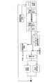
本発明に係る排液リサイクルシステムは塗装工程での洗浄に用いた塗装排水をストックする排水ストックタンク1を備える。この排水ストックタンク1の下流にpH調整、SS除去、重金属除去、フッ素除去および油分除去を行う一次処理部として、第1薬品処理部2、金属吸着部3および第2薬品処理部4を配置している。
The drainage recycling system according to the present invention includes a drainage stock tank 1 for stocking paint drainage used for cleaning in a painting process. A first
第1薬品処理部2及び第2薬品処理部4ではpHを調整する薬剤として、希硫酸または苛性ソーダを用いる。従来は希硫酸ではなく塩酸を用いていたが、塩素濃度を低くするため希硫酸を用いている。
In the first
金属吸着部3では消石灰と高分子凝集剤を用いて重金属などを吸着して沈降させる。従来は消石灰ではなく塩化カルシウムを用いていたが、塩素濃度を低くするため消石灰を用いている。
重金属などを含む濃縮水は後述するCDドライヤー11に送られ上澄み液は第2薬品処理部4に送られ再度pH調整が行われる。
The metal adsorbing unit 3 adsorbs and precipitates heavy metals using slaked lime and a polymer flocculant. Conventionally, calcium chloride is used instead of slaked lime, but slaked lime is used to lower the chlorine concentration.
Concentrated water containing heavy metals and the like is sent to a
第2薬品処理部4を出た水は移送タンク5(中継タンク)に移され、移送タンク5内の水の一部は塗装循環タンクに送られ、残りはCOD低減や塩素低減を行う二次処理部に送られる。この二次処理部は第1フィルター6、活性炭層7、第2フィルター8及び逆浸透膜装置9(RO装置)から構成される。活性炭層7では主としてCOD低減、逆浸透膜装置9では主として塩素低減がなされる。
The water exiting the second chemical treatment unit 4 is transferred to a transfer tank 5 (relay tank), a part of the water in the
CDドライヤーから発生する処理水は純水に近い水質で回収できるため、工業用水レベルで使用する場合はRO(逆浸透膜)装置を介さなくてリサイクルが可能である。 Since the treated water generated from the CD dryer can be recovered with a quality close to that of pure water, it can be recycled without an RO (reverse osmosis membrane) device when used at an industrial water level.
逆浸透膜装置9では金属イオンなどを含んだ濃縮水とこれらを含まない水に分離される。逆浸透膜装置9で分離された水の水質は、pH:6.5〜7.5、塩素濃度:15ppm以下、電導度:110μs/cm以下、COD:13.3ppm以下であり、工業用水の水質レベルである。このため逆浸透膜装置9で分離された重金属を含まない水は純水装置10に送られ、ここで、新たな工業用水と混合され、塗装前処理水洗及び電着水洗に供される。前処理水洗では脱脂水洗と化成水洗が行われ、電着水洗ではディップ水洗と後水洗が行われる。
The reverse
一方、逆浸透膜装置9からの濃縮水はCDドライヤー11に送られる。本実施例では乾燥装置としてCDドライヤーを用いている。
CDドライヤーは図2に示すように、回転ディスク12と、このディスク12に前記濃縮水を吹き付けるノズル13と、前記ディスク12の表面に付着した汚泥を掻き取るスクレーパ14とを備える。
On the other hand, the concentrated water from the reverse
As shown in FIG. 2, the CD dryer includes a rotating
回転ディスク12の下方には重量計付きの循環タンク15が配置され、この循環タンク15に前記濃縮水が送り込まれる。循環タンク15内の濃縮液は循環ポンプ16によって前記ノズル13に送り込まれる
A
また前記ディスク12には高温の蒸気が表面に吹き付けられ、ディスク12の表面は120℃程度に加熱される。CDドライヤーの規模が大きい場合、蒸気リサイクルシステムを設置することにより熱源である蒸気のリサイクルが可能であり、エネルギーコストとCO2の削減が可能となる。したがってディスク12に吹き付けられた濃縮水は乾燥しディスク表面に付着する、この付着物(汚泥)はスクレーパ14で掻き取られ、塗料粕処理装置に送られる。
Further, high temperature steam is blown onto the surface of the
また濃縮水を加熱することで発生した蒸気はフード17で集められ一部は臭気対策シールド18を介して外部に放出され、残りの蒸気はミストセパレータ19においてミストが分離され、このミストは前記ノズル13の途中に送り込まれる。
Further, steam generated by heating the concentrated water is collected by the hood 17 and a part thereof is discharged to the outside through the
またミストセパレータ19を出た蒸気は凝縮器20で凝縮され、凝縮水として回収され、残りの蒸気は排気ファンから放出される。
Moreover, the vapor | steam which exited the
このようにして、本システムに取り込まれた工業用水は、サイクル内で一部は蒸気となって失われるが、のこりの部分は新規に追加される工業用水とレベルは殆ど変わらないので、循環して使用され、河川に放流されることはない。
In this way, industrial water taken into the system, but some in the cycle is lost becomes steam, since part of the remaining industrial water and the level that is newly added hardly changes, circulation Used and never discharged into rivers.
この為、環境負荷の軽減が可能となる。このリサイクルシステム処理から排出される固形物には、塗装工場から排出される塗料及び合成樹脂が多く含まれ、同様に処理された含有廃油についてもきわめて含水率が低く高カロリーの燃料としのサーマルリサイクルが可能となる。 For this reason, the environmental load can be reduced. The solid matter discharged from this recycling system treatment contains a lot of paint and synthetic resin discharged from the coating factory, and the waste oil treated in the same way is also thermally recycled as a fuel with a high calorie and a very low moisture content. Is possible.
本発明に係る排液リサイクルシステムは塗装排液のみならず、工場で発生する排液について応用することが可能である。 The drainage recycling system according to the present invention can be applied not only to coating drainage but also to drainage generated in a factory.
1…排水ストックタンク、2…第1薬品処理部、3…金属吸着部、4…第2薬品処理部、5…移送タンク、6…第1フィルター、7…活性炭層、8…第2フィルター、9…逆浸透膜装置、10…純水装置、11…CDドライヤー、12…回転ディスク、13…ノズル、14…スクレーパ、15…循環タンク、16…循環ポンプ、17…フード、18…臭気対策シールド、19…ミストセパレータ、20…凝縮器。
DESCRIPTION OF SYMBOLS 1 ... Waste water stock tank, 2 ... 1st chemical | medical agent processing part, 3 ... Metal adsorption part, 4 ... 2nd chemical | medical agent processing part, 5 ... Transfer tank, 6 ... 1st filter, 7 ... Activated carbon layer, 8 ... 2nd filter, DESCRIPTION OF
Claims (3)
Priority Applications (4)
| Application Number | Priority Date | Filing Date | Title |
|---|---|---|---|
| JP2012177654A JP5277419B1 (en) | 2012-08-10 | 2012-08-10 | Wastewater recycling system |
| IN703DEN2015 IN2015DN00703A (en) | 2012-08-10 | 2013-05-27 | |
| CN201380041946.6A CN104619653B (en) | 2012-08-10 | 2013-05-27 | Waste liquid recycling system |
| PCT/JP2013/064610 WO2014024544A1 (en) | 2012-08-10 | 2013-05-27 | Waste liquid recycling system |
Applications Claiming Priority (1)
| Application Number | Priority Date | Filing Date | Title |
|---|---|---|---|
| JP2012177654A JP5277419B1 (en) | 2012-08-10 | 2012-08-10 | Wastewater recycling system |
Publications (2)
| Publication Number | Publication Date |
|---|---|
| JP5277419B1 true JP5277419B1 (en) | 2013-08-28 |
| JP2014034017A JP2014034017A (en) | 2014-02-24 |
Family
ID=49179294
Family Applications (1)
| Application Number | Title | Priority Date | Filing Date |
|---|---|---|---|
| JP2012177654A Active JP5277419B1 (en) | 2012-08-10 | 2012-08-10 | Wastewater recycling system |
Country Status (4)
| Country | Link |
|---|---|
| JP (1) | JP5277419B1 (en) |
| CN (1) | CN104619653B (en) |
| IN (1) | IN2015DN00703A (en) |
| WO (1) | WO2014024544A1 (en) |
Families Citing this family (1)
| Publication number | Priority date | Publication date | Assignee | Title |
|---|---|---|---|---|
| JP6110921B1 (en) * | 2015-11-04 | 2017-04-05 | 株式会社荏原製作所 | Slurry processing apparatus and slurry processing method |
Citations (12)
| Publication number | Priority date | Publication date | Assignee | Title |
|---|---|---|---|---|
| JPS4853559A (en) * | 1971-11-05 | 1973-07-27 | ||
| JPH09324986A (en) * | 1996-06-04 | 1997-12-16 | Nishimura Tekkosho:Kk | Dryer for slurry-like material |
| JP2001219176A (en) * | 2000-02-10 | 2001-08-14 | Tokai Plant Eng Kk | Method for treating aqueous paint wastewater |
| JP2002285352A (en) * | 2001-03-27 | 2002-10-03 | Nippon Paint Co Ltd | Metal surface treatment device |
| JP2003326206A (en) * | 2002-05-09 | 2003-11-18 | Toyota Motor Corp | Disc type coating material dregs drying apparatus |
| JP2003326300A (en) * | 2002-05-09 | 2003-11-18 | Toyota Motor Corp | Method and apparatus for drying coating material dregs using disc type drying apparatus |
| JP2003340450A (en) * | 2002-05-30 | 2003-12-02 | Toyota Motor Corp | Method and system for treating heavy metal-containing waste water |
| JP2004016829A (en) * | 2002-06-12 | 2004-01-22 | Parker Engineering Kk | Treatment method of drainage of coating equipment |
| JP2004160396A (en) * | 2002-11-14 | 2004-06-10 | Japan Organo Co Ltd | Ink waste liquid treatment method |
| JP2005000713A (en) * | 2003-06-09 | 2005-01-06 | Japan Organo Co Ltd | Method for treating ink waste liquid |
| JP2006220371A (en) * | 2005-02-10 | 2006-08-24 | Nishimura Tekkosho:Kk | Rotary plate type drier |
| JP2012192331A (en) * | 2011-03-16 | 2012-10-11 | Toyota Motor East Japan Inc | Treatment method for aqueous coating material waste liquid |
Family Cites Families (3)
| Publication number | Priority date | Publication date | Assignee | Title |
|---|---|---|---|---|
| US20040026326A1 (en) * | 2002-06-18 | 2004-02-12 | Canon Kabushiki Kaisha | Liquid treatment method and apparatus |
| CN101244876A (en) * | 2007-02-13 | 2008-08-20 | 三元金属株式会社 | Apparatus for treating waste water for plating preprocessing process and processing method |
| CN102092877B (en) * | 2011-01-05 | 2013-07-03 | 富毅特(上海)环保科技有限公司 | System for comprehensively recycling waste water |
-
2012
- 2012-08-10 JP JP2012177654A patent/JP5277419B1/en active Active
-
2013
- 2013-05-27 WO PCT/JP2013/064610 patent/WO2014024544A1/en active Application Filing
- 2013-05-27 CN CN201380041946.6A patent/CN104619653B/en active Active
- 2013-05-27 IN IN703DEN2015 patent/IN2015DN00703A/en unknown
Patent Citations (12)
| Publication number | Priority date | Publication date | Assignee | Title |
|---|---|---|---|---|
| JPS4853559A (en) * | 1971-11-05 | 1973-07-27 | ||
| JPH09324986A (en) * | 1996-06-04 | 1997-12-16 | Nishimura Tekkosho:Kk | Dryer for slurry-like material |
| JP2001219176A (en) * | 2000-02-10 | 2001-08-14 | Tokai Plant Eng Kk | Method for treating aqueous paint wastewater |
| JP2002285352A (en) * | 2001-03-27 | 2002-10-03 | Nippon Paint Co Ltd | Metal surface treatment device |
| JP2003326206A (en) * | 2002-05-09 | 2003-11-18 | Toyota Motor Corp | Disc type coating material dregs drying apparatus |
| JP2003326300A (en) * | 2002-05-09 | 2003-11-18 | Toyota Motor Corp | Method and apparatus for drying coating material dregs using disc type drying apparatus |
| JP2003340450A (en) * | 2002-05-30 | 2003-12-02 | Toyota Motor Corp | Method and system for treating heavy metal-containing waste water |
| JP2004016829A (en) * | 2002-06-12 | 2004-01-22 | Parker Engineering Kk | Treatment method of drainage of coating equipment |
| JP2004160396A (en) * | 2002-11-14 | 2004-06-10 | Japan Organo Co Ltd | Ink waste liquid treatment method |
| JP2005000713A (en) * | 2003-06-09 | 2005-01-06 | Japan Organo Co Ltd | Method for treating ink waste liquid |
| JP2006220371A (en) * | 2005-02-10 | 2006-08-24 | Nishimura Tekkosho:Kk | Rotary plate type drier |
| JP2012192331A (en) * | 2011-03-16 | 2012-10-11 | Toyota Motor East Japan Inc | Treatment method for aqueous coating material waste liquid |
Also Published As
| Publication number | Publication date |
|---|---|
| CN104619653A (en) | 2015-05-13 |
| WO2014024544A1 (en) | 2014-02-13 |
| CN104619653B (en) | 2016-11-02 |
| IN2015DN00703A (en) | 2015-06-26 |
| JP2014034017A (en) | 2014-02-24 |
Similar Documents
| Publication | Publication Date | Title |
|---|---|---|
| US20150014142A1 (en) | Method for processing waste water using zero process water discharge | |
| JPH10323664A (en) | Wastewater-recovering apparatus | |
| JP2006239578A (en) | Ammonia nitrogen and soluble salt-containing water treatment apparatus and method | |
| JP2008049242A (en) | Garbage leachate treatment system | |
| CN105461102B (en) | A kind of processing method for washing cigarette waste water | |
| JP2008183526A (en) | Method for treating acid waste liquid and alkali waste liquid | |
| JP5277419B1 (en) | Wastewater recycling system | |
| KR102083441B1 (en) | Waste water treatment method containing organic solvent | |
| CN109467239A (en) | A kind of method of iron and steel pickling waste liquid recovery acid | |
| CN110818168A (en) | Smoke washing wastewater zero-discharge technical treatment system and method | |
| JP4295352B1 (en) | Wastewater treatment equipment for reusing water in surface treatment of trivalent chromate and wastewater treatment method for reusing water | |
| CN107473486B (en) | Combined treatment method of desulfurization wastewater | |
| CN107673539B (en) | Acidic wastewater treatment equipment and treatment method | |
| JP3194123B2 (en) | Ultrapure water production and wastewater treatment method for closed system | |
| CN211339161U (en) | Treatment device for realizing zero discharge of desulfurization wastewater by bypass evaporation process | |
| JP3028391B2 (en) | Treatment of plating waste solution | |
| JP2005262004A (en) | Gas washing water treatment device | |
| CN105254100A (en) | System and method for treating sewage containing salt | |
| TWI243155B (en) | Purifying method for leachate in closed-type landfill | |
| JP2002143850A (en) | Device for treating waste water | |
| CN214496015U (en) | Sewage treatment system | |
| CN109942108B (en) | Method for treating oil refining waste alkali liquor | |
| Hafez | Purification of pharmaceutical waste water resulting from herbal plants by zero liquid discharge techniques (ZLD) | |
| Zaharia | Fundamentals of production water management for an industrial productive unit | |
| JP6057429B2 (en) | Solution processing method and processing apparatus |
Legal Events
| Date | Code | Title | Description |
|---|---|---|---|
| TRDD | Decision of grant or rejection written | ||
| R150 | Certificate of patent or registration of utility model |
Free format text: JAPANESE INTERMEDIATE CODE: R150 Ref document number: 5277419 Country of ref document: JP Free format text: JAPANESE INTERMEDIATE CODE: R150 |
|
| R250 | Receipt of annual fees |
Free format text: JAPANESE INTERMEDIATE CODE: R250 |
|
| R250 | Receipt of annual fees |
Free format text: JAPANESE INTERMEDIATE CODE: R250 |
|
| R250 | Receipt of annual fees |
Free format text: JAPANESE INTERMEDIATE CODE: R250 |
|
| R250 | Receipt of annual fees |
Free format text: JAPANESE INTERMEDIATE CODE: R250 |
|
| S531 | Written request for registration of change of domicile |
Free format text: JAPANESE INTERMEDIATE CODE: R313531 |
|
| R350 | Written notification of registration of transfer |
Free format text: JAPANESE INTERMEDIATE CODE: R350 |
|
| R250 | Receipt of annual fees |
Free format text: JAPANESE INTERMEDIATE CODE: R250 |
|
| R250 | Receipt of annual fees |
Free format text: JAPANESE INTERMEDIATE CODE: R250 |
|
| R250 | Receipt of annual fees |
Free format text: JAPANESE INTERMEDIATE CODE: R250 |
|
| R250 | Receipt of annual fees |
Free format text: JAPANESE INTERMEDIATE CODE: R250 |
|
| R250 | Receipt of annual fees |
Free format text: JAPANESE INTERMEDIATE CODE: R250 |