JP5277108B2 - Multi-plate clutch - Google Patents
Multi-plate clutch Download PDFInfo
- Publication number
- JP5277108B2 JP5277108B2 JP2009179282A JP2009179282A JP5277108B2 JP 5277108 B2 JP5277108 B2 JP 5277108B2 JP 2009179282 A JP2009179282 A JP 2009179282A JP 2009179282 A JP2009179282 A JP 2009179282A JP 5277108 B2 JP5277108 B2 JP 5277108B2
- Authority
- JP
- Japan
- Prior art keywords
- clutch
- cam
- plate
- recess
- output member
- Prior art date
- Legal status (The legal status is an assumption and is not a legal conclusion. Google has not performed a legal analysis and makes no representation as to the accuracy of the status listed.)
- Active
Links
- 230000007246 mechanism Effects 0.000 claims abstract description 63
- 230000001133 acceleration Effects 0.000 claims abstract description 5
- 230000005540 biological transmission Effects 0.000 claims description 16
- 230000000694 effects Effects 0.000 description 7
- 239000010687 lubricating oil Substances 0.000 description 6
- 230000009467 reduction Effects 0.000 description 4
- 239000000463 material Substances 0.000 description 2
- 230000002093 peripheral effect Effects 0.000 description 2
- 230000004044 response Effects 0.000 description 2
- 238000004904 shortening Methods 0.000 description 2
- 238000009825 accumulation Methods 0.000 description 1
- 230000008859 change Effects 0.000 description 1
- 230000008878 coupling Effects 0.000 description 1
- 238000010168 coupling process Methods 0.000 description 1
- 238000005859 coupling reaction Methods 0.000 description 1
- 238000005516 engineering process Methods 0.000 description 1
Images


Classifications
-
- F—MECHANICAL ENGINEERING; LIGHTING; HEATING; WEAPONS; BLASTING
- F16—ENGINEERING ELEMENTS AND UNITS; GENERAL MEASURES FOR PRODUCING AND MAINTAINING EFFECTIVE FUNCTIONING OF MACHINES OR INSTALLATIONS; THERMAL INSULATION IN GENERAL
- F16D—COUPLINGS FOR TRANSMITTING ROTATION; CLUTCHES; BRAKES
- F16D13/00—Friction clutches
- F16D13/22—Friction clutches with axially-movable clutching members
- F16D13/38—Friction clutches with axially-movable clutching members with flat clutching surfaces, e.g. discs
- F16D13/52—Clutches with multiple lamellae ; Clutches in which three or more axially moveable members are fixed alternately to the shafts to be coupled and are pressed from one side towards an axially-located member
- F16D13/54—Clutches with multiple lamellae ; Clutches in which three or more axially moveable members are fixed alternately to the shafts to be coupled and are pressed from one side towards an axially-located member with means for increasing the effective force between the actuating sleeve or equivalent member and the pressure member
- F16D13/56—Clutches with multiple lamellae ; Clutches in which three or more axially moveable members are fixed alternately to the shafts to be coupled and are pressed from one side towards an axially-located member with means for increasing the effective force between the actuating sleeve or equivalent member and the pressure member in which the clutching pressure is produced by springs only
- F16D2013/565—Clutches with multiple lamellae ; Clutches in which three or more axially moveable members are fixed alternately to the shafts to be coupled and are pressed from one side towards an axially-located member with means for increasing the effective force between the actuating sleeve or equivalent member and the pressure member in which the clutching pressure is produced by springs only with means for releasing the clutch pressure in case of back torque
Landscapes
- Engineering & Computer Science (AREA)
- General Engineering & Computer Science (AREA)
- Mechanical Engineering (AREA)
- Mechanical Operated Clutches (AREA)
- One-Way And Automatic Clutches, And Combinations Of Different Clutches (AREA)
Abstract
Description
本発明は、入力部材に連結されるクラッチアウタと、出力部材に連結されるクラッチインナと、前記クラッチアウタに係合される複数枚の駆動摩擦板と、それらの駆動摩擦板と交互に重ね合わされて前記クラッチインナに係合される複数枚の被動摩擦板と、複数枚ずつの前記駆動摩擦板および前記被動摩擦板を前記クラッチインナとの間に挟む挟圧板と、前記駆動摩擦板および前記被動摩擦板を前記クラッチインナおよび前記挟圧板間に挟圧する側に前記クラッチインナまたは前記挟圧板を付勢するクラッチばねと、第1凹部が設けられる第1カム部材ならびに第1凹部に挿入される第1凸部が設けられる第2カム部材で構成されるアシストカム機構とを備え、前記入力部材から前記出力部材への動力伝達状態での第1凹部および第1凸部の当接面の少なくとも一方が前記動力伝達状態での加速時に前記クラッチばねの付勢力を強めるべく傾斜面として形成される多板式クラッチに関する。 According to the present invention, a clutch outer coupled to an input member, a clutch inner coupled to an output member, a plurality of drive friction plates engaged with the clutch outer, and the drive friction plates are alternately stacked. A plurality of driven friction plates engaged with the clutch inner, a plurality of the driving friction plates and a pinching plate sandwiching the driven friction plates between the clutch inner, the driving friction plate and the driven friction plate. A clutch spring that biases the clutch inner or the clamping plate on the side that clamps the dynamic friction plate between the clutch inner and the clamping plate, a first cam member provided with a first recess, and a first cam member that is inserted into the first recess. An assist cam mechanism configured by a second cam member provided with one convex portion, and a first concave portion and a first convex portion in a state of power transmission from the input member to the output member. It relates to a multi-plate clutch in which at least one of the contact surface is formed as an inclined surface to enhance the urging force of the clutch spring during acceleration in the power transmission state.
動力伝達状態での加速時にはクラッチカム部材を引き込んでクラッチばねの付勢力を強めて駆動摩擦板および被動摩擦板の圧接力を高め、減速時には前記クラッチカム部材を押し出してクラッチばねの付勢力を弱めて駆動摩擦板および被動摩擦板の圧接力を抑えるようにしたカム機構を備えた所謂アシスト・スリッパークラッチ装置が、特許文献1で知られている。 When accelerating in the power transmission state, the clutch cam member is pulled in to increase the urging force of the clutch spring to increase the pressing force of the driving friction plate and the driven friction plate, and during deceleration, the clutch cam member is pushed out to weaken the urging force of the clutch spring. A so-called assist slipper clutch device having a cam mechanism that suppresses the pressure contact force between the driving friction plate and the driven friction plate is known from Patent Document 1.
ところで、エンジン出力の増加に伴う多板式クラッチの大型化が必要な車両にあっては、クラッチばねのばね荷重を大きく設定せざるを得ず、ひいては操作荷重が大きくなってしまうので、上記特許文献1で開示されるように、凸部および凹部にそれぞれ形成された傾斜面を当接させることで、加速時にはクラッチカム部材を引き込んで駆動摩擦板および被動摩擦板の圧接力を高め、アシスト効果を得るようにした技術を適用することが望まれる。しかるに、たとえば引き込み力によるクラッチ操作荷重の低減効果を充分に得ながら、過大な引き込み力が発生した場合には唐突なクラッチ接続感が発生することを抑制する必要があることから、それらの均衡がとれた傾斜面の角度設定をする際には、様々な角度のカム機構を準備した上で、各要件のテストを実施して最適な角度を特定するまでに、相当の期間を要する。 By the way, in a vehicle that requires an increase in the size of a multi-plate clutch accompanying an increase in engine output, the spring load of the clutch spring must be set large, and as a result, the operation load becomes large. As disclosed in FIG. 1, by contacting the inclined surfaces formed respectively on the convex portion and the concave portion, the clutch cam member is pulled in at the time of acceleration to increase the pressure contact force of the driving friction plate and the driven friction plate, and the assist effect is obtained. It is desirable to apply the technology that has been obtained. However, for example, it is necessary to suppress the occurrence of a sudden clutch connection when an excessive pulling force is generated while sufficiently reducing the clutch operation load due to the pulling force. When setting the angle of the inclined surface taken, it takes a considerable period of time to prepare the cam mechanism of various angles and to perform the test of each requirement to identify the optimum angle.
そこで本願の発明者は、傾斜面の角度についての各要件のテストを行い、クラッチ操作荷重の低減効果を充分に得つつ、唐突なクラッチ接続感の発生を抑制することのできる最適な角度範囲があることを見い出した。 Therefore, the inventor of the present application tests each requirement regarding the angle of the inclined surface, and there is an optimum angle range that can suppress the occurrence of a sudden clutch connection feeling while sufficiently obtaining the effect of reducing the clutch operation load. I found something.
本発明は、かかる事情に鑑みてなされたものであり、クラッチ操作荷重の低減効果を充分に得つつ、唐突なクラッチ接続感の発生を抑制し得るようにした多板式クラッチを提供することを目的とする。 The present invention has been made in view of such circumstances, and an object of the present invention is to provide a multi-plate clutch capable of suppressing the occurrence of sudden clutch connection feeling while sufficiently obtaining the effect of reducing the clutch operation load. And
上記目的を達成するために、本発明は、入力部材に連結されるクラッチアウタと、出力部材に連結されるクラッチインナと、前記クラッチアウタに係合される複数枚の駆動摩擦板と、それらの駆動摩擦板と交互に重ね合わされて前記クラッチインナに係合される複数枚の被動摩擦板と、複数枚ずつの前記駆動摩擦板および前記被動摩擦板を前記クラッチインナとの間に挟む挟圧板と、前記駆動摩擦板および前記被動摩擦板を前記クラッチインナおよび前記挟圧板間に挟圧する側に前記クラッチインナまたは前記挟圧板を付勢するクラッチばねと、第1凹部が設けられる第1カム部材ならびに第1凹部に挿入される第1凸部が設けられる第2カム部材で構成されるアシストカム機構とを備え、前記入力部材から前記出力部材への動力伝達状態での第1凹部および第1凸部の当接面の少なくとも一方が前記動力伝達状態での加速時に前記クラッチばねの付勢力を強めるべく傾斜面として形成される湿式タイプの多板式クラッチにおいて、前記傾斜面のクラッチ中心軸線に直交する平面との交差角度が、80度〜85度の範囲に設定され、前記第1凹部の周囲の壁部のうち前記傾斜面が形成される特定の壁部が少なくとも該特定の壁部の周囲よりも隆起して形成され、前記第1カム部材の半径方向に沿う前記第1凹部の外端が開放していることを第1の特徴とする。 To achieve the above object, the present invention provides a clutch outer coupled to an input member, a clutch inner coupled to an output member, a plurality of drive friction plates engaged with the clutch outer, A plurality of driven friction plates that are alternately overlapped with the driving friction plates and engaged with the clutch inner; and a plurality of the driving friction plates and a pressure plate that sandwiches the driven friction plates between the clutch inner and the clutch inner; A clutch spring that biases the clutch inner or the pressure plate on the side where the drive friction plate and the driven friction plate are clamped between the clutch inner and the pressure plate, a first cam member provided with a first recess, and An assist cam mechanism configured by a second cam member provided with a first convex portion to be inserted into the first concave portion, and in a power transmission state from the input member to the output member In multi-plate clutch of a wet type that is formed as an inclined surface to at least one of the first recess and abutment surface of the first convex portion strengthen the biasing force of the clutch spring when accelerating in the power transmission state, the inclined surface The crossing angle with the plane perpendicular to the clutch central axis is set in the range of 80 to 85 degrees, and at least the specific wall portion on which the inclined surface is formed is the wall portion around the first recess. are formed by raised than the surrounding certain wall portion, that the outer end of the first recess along a radial direction of the first cam member is open shall be the first feature.
また本発明は、第1の特徴の構成に加えて、第2凹部が設けられる第3カム部材と、第2凹部に挿入される第2凸部が設けられる第4カム部材とで構成されるとともに、前記出力部材から前記入力部材へのバックトルク伝達状態での第2凹部および第2凸部の当接面の少なくとも一方が前記バックトルクの増加に応じて前記クラッチばねの付勢力を弱めるべく傾斜面として形成されるバックトルクリミッタ機構を備え、第2凹部および第2凸部の当接面の少なくとも一方に形成される前記傾斜面のクラッチ中心軸線に直交する平面との交差角度が、前記アシストカム機構の前記傾斜面の前記交差角度と同一に設定されることを第2の特徴とする。 In addition to the configuration of the first feature, the present invention includes a third cam member provided with a second recess and a fourth cam member provided with a second projection inserted into the second recess. In addition, at least one of the contact surface of the second concave portion and the second convex portion in the back torque transmission state from the output member to the input member should reduce the urging force of the clutch spring according to the increase of the back torque. A back torque limiter mechanism formed as an inclined surface is provided, and an intersection angle of the inclined surface formed on at least one of the contact surface of the second concave portion and the second convex portion with a plane perpendicular to the clutch central axis is A second feature is that the angle is set to be the same as the crossing angle of the inclined surface of the assist cam mechanism.
本発明は、第2の特徴の構成に加えて、前記第3カム部材の半径方向に沿う前記第2凹部の外端が開放していることを第3の特徴とする。 The present invention, in addition to the second feature, a third feature that the outer end of the second recess along a radial direction of the third cam member is opened.
本発明は、第2または第3の特徴の構成に加えて、前記第1および第3カム部材が前記出力部材に同軸に固定され、複数の前記第1および第2凹部の少なくとも一方が、前記第1および第3カム部材の周方向等間隔に配置されることを第4の特徴とする。 According to the present invention, in addition to the configuration of the second or third feature, the first and third cam members are coaxially fixed to the output member, and at least one of the plurality of first and second recesses is the A fourth feature is that the first and third cam members are arranged at equal intervals in the circumferential direction.
本発明は、第2〜第4の特徴の構成に加えて、前記第1および第3カム部材として機能するようにして前記出力部材に固定される単一のセンターカムに、前記出力部材の軸方向一側に開放する第1凹部と、前記出力部材の軸方向他側に開放する第2凹部とが、前記軸方向での位置を同一として設けられることを第5の特徴とする。 In addition to the configurations of the second to fourth features, the present invention provides a single center cam fixed to the output member so as to function as the first and third cam members. A fifth feature is that the first recess opened to one side in the direction and the second recess opened to the other axial side of the output member are provided at the same position in the axial direction.
本発明は、第5の特徴の構成に加えて、前記センターカムは、前記出力部材に固定される円筒状のボス部と、該ボス部の軸方向中間部から半径方向外方に張り出す鍔部とを一体に有し、該鍔部の一部を形成して前記出力部材の軸線と直交する平面に沿う平板部分が複数の前記第2凹部の開口端に連設されることを第6の特徴とする。 According to the present invention, in addition to the configuration of the fifth feature, the center cam includes a cylindrical boss portion fixed to the output member, and a flange projecting radially outward from an intermediate portion in the axial direction of the boss portion. and a parts together, that the flat plate portion along a plane perpendicular to the axis of the output member form part of the collar portion is provided continuously to the opening ends of the plurality of the second recess 6 It is characterized by.
さらに本発明は、第6の特徴の構成に加えて、前記第1凹部が、前記平板部分の一面から突出する第1および第2壁部間に形成され、前記第2凹部は、前記平板部分の一面から突出する第3および第4壁部ならびに第3および第4壁部の突出端を一体に連結する連結壁部とで形成され、第1および第3壁部間ならびに第2および第4壁部間で前記平板部分の一面が円弧状に凹んで形成されることを第7の特徴とする。 Furthermore, in the present invention, in addition to the configuration of the sixth feature, the first concave portion is formed between first and second wall portions protruding from one surface of the flat plate portion, and the second concave portion is formed by the flat plate portion. The third and fourth wall portions projecting from one surface, and the connecting wall portion integrally coupling the projecting ends of the third and fourth wall portions, and between the first and third wall portions and the second and fourth portions. A seventh feature is that one surface of the flat plate portion is recessed in a circular arc shape between the wall portions.
なお実施の形態のメインシャフト11が本発明の出力部材に対応し、実施の形態の一次被動歯車16が本発明の入力部材に対応し、実施の形態の受圧板21が本発明の挟圧板に対応し、実施の形態のセンターカム25が本発明の第1および第3カム部材に対応し、実施の形態のアシストカム26が本発明の第2カム部材に対応し、実施の形態のスリッパカム27が本発明の第4カム部材に対応する。
The
本発明の第1の特徴によれば、第1凹部および第1凸部の当接面の少なくとも一方に形成される傾斜面のクラッチ中心軸線と直交する平面に対して交差する交差角度が、80度〜85度の範囲に設定されるので、車両の発進性およびアシスト効果を両立させた多板式クラッチを得ることができる。すなわち本願の発明者は、前記交差角度が80度未満では、クラッチ接続時にアシストカム機構によって生じる圧接力が過大となり、発進時に唐突なクラッチ接続感が発生して発進性能に影響を与えてしまい、前記交差角度が85度を超えると、効果的な圧接力が発生せず、アシストカム機構によるクラッチ操作荷重の低減効果が小さくなってしまうことを確認した。したがってアシストカム機構を備える多板式クラッチにおいて、アシストカム機構の傾斜面の前記交差角度を上記範囲に設定することにより、発進性能を満足しながら効果的なアシスト力を得ることができるようになり、最適な角度を設定するために相当の期間を要していた従来に比べて各要件のテスト期間を短縮しながら、最適な角度を絞り込めるようにして設計工数の低減を図ることができる。 According to the first feature of the present invention, the crossing angle intersecting the plane perpendicular to the clutch center axis of the inclined surface formed on at least one of the contact surface of the first concave portion and the first convex portion is 80. Since the angle is set in a range of 85 to 85 degrees, a multi-plate clutch that achieves both vehicle startability and assist effect can be obtained. That is, the inventor of the present application, if the crossing angle is less than 80 degrees, the pressure contact force generated by the assist cam mechanism at the time of clutch connection becomes excessive, and a sudden clutch connection feeling is generated at the time of start, and the start performance is affected. It has been confirmed that when the crossing angle exceeds 85 degrees, an effective pressure contact force is not generated and the effect of reducing the clutch operation load by the assist cam mechanism is reduced. Therefore, in a multi-plate clutch provided with an assist cam mechanism, an effective assist force can be obtained while satisfying the starting performance by setting the intersecting angle of the inclined surfaces of the assist cam mechanism within the above range. It is possible to reduce the design man-hours by narrowing down the optimum angle while shortening the test period of each requirement as compared with the conventional case where a considerable period is required to set the optimum angle.
また、傾斜面が形成される壁部を、少なくとも壁部の周囲よりも隆起して形成することで、傾斜面に必要な面積を確保しつつ第1カム部材の軽量化を図ることができる。 In addition , by forming the wall portion on which the inclined surface is formed so as to protrude at least from the periphery of the wall portion, it is possible to reduce the weight of the first cam member while ensuring a necessary area for the inclined surface.
さらに湿式タイプの多板式クラッチにおいて、第1凹部の半径方向外端を開放することで、第1凹部内から潤滑油を良好に排出できるようにし、潤滑油が第1凹部に過剰に溜まることによるアシストカム機構の作動への影響を抑制することができる。Further, in the wet type multi-plate clutch, by opening the outer end in the radial direction of the first recess, the lubricating oil can be discharged well from the first recess, and the lubricating oil accumulates excessively in the first recess. The influence on the operation of the assist cam mechanism can be suppressed.
また本発明の第2の特徴によれば、バックトルク増加時にクラッチばねの付勢力を弱めるバックトルクリミッタ機構における傾斜面のクラッチ中心軸線に直交する平面との交差角度を、アシストカム機構における傾斜面の前記交差角度と同一に設定することで、アシストカム機構およびバックトルクリミッタ機構で部品を共用化することを可能とし、専用部品を削減してコストを低減することができる。 According to the second feature of the present invention, the angle of intersection of the inclined surface of the back torque limiter mechanism that weakens the urging force of the clutch spring when the back torque is increased with the plane perpendicular to the clutch central axis is set to By setting the same angle as the crossing angle, it is possible to share parts with the assist cam mechanism and the back torque limiter mechanism, and it is possible to reduce the cost by reducing dedicated parts.
本発明の第3の特徴によれば、湿式タイプの多板式クラッチにおいて、第1及び第2凹部の半径方向外端を開放することで、第1および第2凹部内から潤滑油を良好に排出できるようにし、潤滑油が第1および第2凹部に過剰に溜まることによるアシストカム機構およびバックトルクリミッタ機構の作動への影響を抑制することができる。 According to the third aspect of the present invention, in the wet type multi-plate clutch, the lubricating oil can be discharged well from the first and second recesses by opening the radially outer ends of the first and second recesses. Thus, the influence on the operation of the assist cam mechanism and the back torque limiter mechanism due to excessive accumulation of the lubricating oil in the first and second recesses can be suppressed.
本発明の第4の特徴によれば、複数の第1および第2凹部の少なくとも一方が、出力部材に同軸に固定される第1および第3カム部材の周方向等間隔に配置されるので、第2および第4カム部材の少なくとも一方が当接することによって発生する力を第1および第3カム部材の少なくとも一方で周方向に均等に分散せしめ、カム機構の作動を確実なものとすることができる。 According to the fourth feature of the present invention, at least one of the plurality of first and second recesses is arranged at equal intervals in the circumferential direction of the first and third cam members fixed coaxially to the output member. The force generated by the contact of at least one of the second and fourth cam members is evenly distributed in the circumferential direction of at least one of the first and third cam members to ensure the operation of the cam mechanism. it can.
本発明の第5の特徴によれば、第1および第3カム部材として機能する単一のセンターカムが出力部材に固定されるので、部品点数を低減するとともに第1および第3カム部材の配置スペースを小さくすることができ、しかも第1凹部および第2凹部が、出力部材の軸方向での位置を同一としてセンターカムに設けられるので、第1および第2凹部を配置するための出力部材の軸方向に沿うスペースを小さくして、アシストカム機構およびバックトルクリミッタ機構のコンパクト化を図ることができる。 According to the fifth aspect of the present invention, since the single center cam that functions as the first and third cam members is fixed to the output member, the number of parts is reduced and the arrangement of the first and third cam members is reduced. Since the space can be reduced and the first recess and the second recess are provided in the center cam with the same position in the axial direction of the output member, the output member for disposing the first and second recesses is provided. The space along the axial direction can be reduced, and the assist cam mechanism and the back torque limiter mechanism can be made compact.
本発明の第6の特徴によれば、センターカムが備える鍔部の一部を構成して出力部材の軸線と直交する平面に沿う平板部分が複数の第2凹部の開口端に連設されるので、作用する力が比較的大きくなるバックトルクリミッタ機構の一部を構成する第2凹部の開口端を平板部分で補強することができる。 According to the sixth aspect of the present invention, a flat plate portion that forms a part of the collar portion of the center cam and extends along a plane orthogonal to the axis of the output member is connected to the open ends of the plurality of second recesses. Therefore, the opening end of the second concave portion constituting a part of the back torque limiter mechanism in which the acting force is relatively large can be reinforced by the flat plate portion.
さらに本発明の第7の特徴によれば、第1凹部および第2凹部間で平板部分の一面が円弧状に凹んで形成されるので、第1凹部および第2凹部の周方向両側を形成する壁部および平板部分の連設部を彎曲させて厚肉とし、前記連設部の強度を高めることができる。 Further, according to the seventh feature of the present invention, since one surface of the flat plate portion is formed in an arc shape between the first recess and the second recess, both sides in the circumferential direction of the first recess and the second recess are formed. The connecting portion of the wall portion and the flat plate portion can be bent to be thick, and the strength of the connecting portion can be increased.
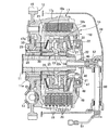
以下、本発明の実施の形態を添付の図1〜図6に基づいて説明すると、先ず図1において、たとえば自動二輪車に搭載されるエンジンのクランクシャフト(図示せず)と、歯車変速機(図示せず)のメインシャフト11との間に、一次減速装置12、ダンパばね13および多板式クラッチ14が介設され、前記一次減速装置12は、クランクシャフトに設けられる一次駆動歯車(図示せず)と、一次駆動歯車に噛合する一次被動歯車16とから成り、一次被動歯車16は前記メインシャフト11に相対回転可能に支承される。
DESCRIPTION OF THE PREFERRED EMBODIMENTS Embodiments of the present invention will be described below with reference to FIGS. 1 to 6. First, referring to FIG. 1, for example, an engine crankshaft (not shown) mounted on a motorcycle and a gear transmission (see FIG. A primary
前記多板式クラッチ14は、湿式タイプのものであり、入力部材である前記一次被動歯車16にダンパばね13を介して連結されるクラッチアウタ17と、該クラッチアウタ17内に同軸に配置される円筒部18aならびに該円筒部18aの一端に一体に連設される加圧板部18bを有するクラッチインナ18と、前記クラッチアウタ17に相対回転不能に係合される複数枚の駆動摩擦板19,19…と、それらの駆動摩擦板19,19…と交互に配置されて前記クラッチインナ18の前記円筒部18aに相対回転不能に係合される複数枚の被動摩擦板20,20…と、相互に重なった前記駆動摩擦板19,19…および前記被動摩擦板20,20…を前記加圧板部18bとの間に挟んで出力部材である前記メインシャフト11に固定される挟圧板としての受圧板21と、前記駆動摩擦板19,19…および前記被動摩擦板20,20…を前記クラッチインナ18および前記受圧板21間に挟圧する側に前記クラッチインナ18を付勢するクラッチばね22と、前記一次被動歯車16から前記メインシャフト11への動力伝達状態での加速時に前記クラッチばね22の付勢力を強めるアシストカム機構23と、前記メインシャフト11から前記一次被動歯車16へのバックトルク伝達状態でのバックトルク増加時に前記クラッチばね22の付勢力を弱めるバックトルクリミッタ機構24とを備える。
The multi-plate clutch 14 is of a wet type, and includes a clutch outer 17 that is connected to the primary driven
前記クラッチアウタ17は、前記クラッチインナ18の円筒部18aを同軸に囲繞する円筒部17aと、該円筒部17aの前記一次被動歯車16側端部に連なる端壁部17bとを一体に有して、一次被動歯車16と反対側に開放した椀状に形成されており、複数枚の駆動摩擦板19,19…の外周部が、軸方向の移動を可能とするとともに相対回転を不能として前記円筒部17aに係合される。
The clutch outer 17 integrally includes a
前記一次減速装置12に対応する部分で前記メインシャフト11の外周には、前記多板式クラッチ14側に臨む環状段部11aが形成されており、メインシャフト11の外周に嵌装される円筒状のスリーブ28の前記多板式クラッチ14とは反対側の端部が前記環状段部11aに当接され、このスリーブ28の外周と、前記一次被動歯車16の内周との間にニードルベアリング29が介装される。
An
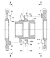
前記円筒部18aの半径方向内方には、前記アシストカム機構23の一部を構成する第1カム部材として機能するとともに前記バックトルクリミッタ機構24の一部を構成する第3カム部材としても機能するセンターカム25が配置される。このセンターカム25は、前記メインシャフト11の外周にスプライン係合される円筒状のボス部25aと、該ボス部25aの軸方向中間部から半径方向外方に張り出してメインシャフト11の軸方向に直交する平面内に配置される鍔部25bとを一体に有する。
Inside the
一方、前記受圧板21は、図1で示すように円板状に形成されており、この受圧板21の内周部は、前記ボス部25aの前記一次減速装置12側の端部外周にスプライン係合されるとともに、前記ボス部25aの前記一次減速装置12側の端部および前記スリーブ28間に挟まれる押さえ板30と、ボス部25aとの間に挟持されることによってボス部25aに固定される。
On the other hand, the
またメインシャフト11の一端部には、前記センターカム25におけるボス部25aの一端との間に環状のばね受け部材31を挟むナット32が螺合されており、このナット32を締め付けることにより、前記環状段部11aおよびナット32間に、スリーブ28、押さえ板30、センターカム25のボス部25aおよびばね受け部材31が挟持され、ボス部25aはメインシャフト11の外周にスプライン係合されているので、センターカム25および受圧板21はメインシャフト11に固定されることになる。
Further, a
前記クラッチばね22は、前記メインシャフト11に固定されるばね受け部材31と、前記クラッチインナ18の円筒部18aに摺動可能に嵌合される環状のばね受け部材33との間に設けられる皿ばねであり、このクラッチばね22は、前記円筒部18aの内周に設けられて前記ばね受け部材33をクラッチばね22とは反対側から受ける環状段部34に前記ばね受け部材33を押しつけるものである。而してクラッチインナ18はその加圧板部18bを受圧板部21に近接させる側、すなわち駆動摩擦板19,19…および被動摩擦板20,20…を摩擦係合させて多板式クラッチ14を接続状態とする側にクラッチばね22によって付勢されることになる。
The
前記アシストカム機構23は、一次被動歯車16から入力される駆動力の増加に応じて前記加圧板部18bを前記受圧板21に近接させる側に前記クラッチインナ18を移動させるものであり、第1カム部材として前記メインシャフト11に固定されるセンターカム25と、該センターカム25における鍔部25bの一面に対向するようにして前記クラッチインナ18の円筒部18aにスプライン係合される第2カム部材としてのアシストカム26とで構成される。またバックトルクリミッタ機構24は、前記メインシャフト11からのバックトルクの増加に応じて前記加圧板部18bを前記受圧板21から離間させる側に前記クラッチインナ18を移動させるものであり、第1カム部材として機能するとともに第3カム部材としても機能する前記センターカム25と、該センターカム25の鍔部25bの他面に対向するようにして前記クラッチインナ18の円筒部18aにスプライン係合される第4カム部材としてのスリッパカム27とで構成される。
The
前記アシストカム26は、センターカム25の鍔部25bおよび受圧板21間でクラッチインナ18の円筒部18aにスプライン係合されるものであり、アシストカム26および受圧板21間には、アシストカム26をセンターカム25の鍔部25bに近接する側にばね付勢する皿ばね35が介設される。
The
一方、前記スリッパカム27は、前記センターカム25の鍔部25bと、前記クラッチインナ18の円筒部18aに摺動可能に嵌合される環状のばね受け部材33との間でクラッチインナ18の円筒部18aにスプライン係合されるものであり、前記メインシャフト11に固定されるばね受け部材31および前記ばね受け部材33との間にクラッチばね22が設けられるので、センターカム25の鍔部25bから離反する側へのスリッパカム27の軸方向移動は前記ばね受け部材33で規制されることになる。
On the other hand, the
図2〜図4を併せて参照して、アシストカム機構23は、前記センターカム25の鍔部25bにおける一面に設けられる複数の第1凹部37…に、前記アシストカム26に突設される複数の第1突部38…がそれぞれ挿入されて成る。
2 to 4, the
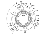
図5を併せて参照して、バックトルクリミッタ機構24は、前記センターカム25の鍔部25bにおける他面に設けられる複数の第2凹部40…に、前記スリッパカム27に突設される複数の第2突部41…がそれぞれ挿入されて成る。
Referring also to FIG. 5, the back
図6を併せて参照して、前記センターカム25の鍔部25bは、前記ボス部25aの外周から半径方向外方に突出するリング部分25baと、該リング部分25baの前記スリッパカム27側の端部から半径方向外方に張り出してメインシャフト11の軸線に直交する平面に沿う平板部分25bbとを一体に有するものである。
Referring also to FIG. 6, the
第1凹部37は、センターカム25の周方向に間隔をあけて対向して前記平板部分25bbの一面から前記アシストカム26側に突出するとともにセンターカム25の半径方向に沿う内端を前記リング部分25baに連設せしめた第1および第2壁部56,57間に形成されており、アシストカム26側に開放するとともにセンターカム25の半径方向に沿う外端を開放するものであり、複数個たとえば3個の第1凹部37…が、センターカム25における鍔部25bの一面に設けられる。
The first
また第2凹部40は、センターカム25の周方向に間隔をあけて対向して前記平板部分25bbの一面から前記アシストカム26側に突出するとともにセンターカム25の半径方向に沿う内端を前記リング部分25baに連設せしめた第3および第4壁部58,59と、それらの壁部58,59の突出端を一体に連結して前記リング部分25baに連なる連結壁部60とで形成されており、スリッパカム27側に開放するとともにセンターカム25の半径方向に沿う外端を開放するものであり、複数個たとえば3個の第2凹部40…が、センターカム25における鍔部25bの他面に設けられる。しかも鍔部25bの平板部分25bbは第2凹部40…の開口端に連設される。
Further, the
複数個たとえば3個ずつの第1凹部37…および第2凹部40…の少なくとも一方、この実施の形態では両方が、センターカム25の周方向等間隔に配置されており、第1凹部37…が相互間の中心角度βを同一としてセンターカム25の周方向等間隔に配置され、第2凹部40…が相互間の中心角度γを同一としてセンターカム25の周方向等間隔に配置されており、β=γである。しかも第2凹部40…は、第1凹部37…相互間に位置するように配置される。
In this embodiment, at least one of a plurality of, for example, three each of the
また第1凹部37…と、第2凹部40…とは、メインシャフト11の軸方向に沿う位置を同一として前記センターカム25の鍔部25bに設けられており、第1凹部37…の周方向両側を形成する第1壁部56…および第2壁部57…のアシストカム26側突出端と、第2凹部40…の閉塞端を形成する連結壁部60…の外面とは、メインシャフト11の軸線に直交する第1の平面PA上に在り、第1凹部37…の閉塞端を形成する平板部分25bbの外面と、第2凹部40…の周方向両側を形成する第3壁部58…および第4壁部59…のスリップカム27側の突出端とは、メインシャフト11の軸線に直交する第2の平面PB上に在る。
The first recesses 37 and the
図6に注目して、接続状態にある多板式クラッチ14を介して一次被動歯車16からメインシャフト11に動力が伝達されているときにクラッチインナ18の回転方向が、矢印39で示す方向であるときに、前記第1凹部37…の前記回転方向39に沿う前側面すなわち第1壁部56の内側面に前記第1突部38…の前記回転方向に沿う前側面が当接するものであり、この状態での第1凹部37…および第1突部38…の当接面の少なくとも一方、この実施の形態では両方が、アシストカム26側に向かうにつれて前記回転方向39に沿う前方に位置するように傾斜した傾斜面37a…,38a…として形成される。
Referring to FIG. 6, the rotation direction of the clutch inner 18 is the direction indicated by the
而して一次被動歯車16からメインシャフト11間のトルク伝達状態での加速側のトルク変動が生じたときには、アシストカム26における第1突部38…の傾斜面38a…が、センターカム25の鍔部25bにおける第1凹部37…の傾斜面37a…に当接し、アシストカム26には、センターカム25の鍔部25bから離反する側の力が鍔部25bから作用し、クラッチばね22の付勢力を打ち消す方向で皿ばね35から作用していた逆向きの付勢力を弱め、クラッチばね22による付勢力を完全に発揮させて駆動摩擦板19,19…および被動摩擦板20,20…の圧縮力を高めることになる。
Thus, when a torque fluctuation on the acceleration side in the state of torque transmission from the primary driven
また多板式クラッチ14が接続状態にあるときにメインシャフト11から一次被動歯車16にバックトルクが伝達されているときのセンターカム25の回転方向が矢印42で示す方向であるときに、前記第2凹部40…の前記回転方向42に沿う後側面が第2突部41…の前記回転方向42に沿う後側面すなわち第3壁部58の内側面に当接するものであり、この状態での第2凹部40…および第2突部41…の当接面の少なくとも一方、この実施の形態では両方が、スリッパカム27側に向かうにつれて前記回転方向42に沿う後方に位置するように傾斜した傾斜面40a…,41a…として形成される。
Further, when the rotation direction of the
而してバックトルク伝達状態でのバックトルク増加時には、スリッパカム27における第2突部41…の傾斜面41a…に、センターカム25の鍔部25bにおける第2凹部40…の傾斜面40aが当接し、スリッパカム27には、センターカム25の鍔部25bから離反する側の力が鍔部25bから作用し、これによってクラッチばね22の付勢力が弱められ、駆動摩擦板19,19…および被動摩擦板20,20…の圧縮力が弱められることになる。
Thus, when the back torque is increased in the back torque transmission state, the
しかも前記傾斜面37a…,38a…,40a…,41a…がクラッチ中心軸線に直交する平面PLに対して交差する交差角度αは、本願発明者の実験に基づいて、80度〜85度の範囲に設定される。
Moreover, the crossing angle α at which the
ところで前記アシストカム26および前記スリッパカム27は、同一の素材によって同一形状に形成されるものであり、アシストカム26の第1突部38…ならびにスリッパカム27の第2突部41…は同一形状であり、センターカム25における鍔部25aの一面に設けられる第1凹部37…ならびに前記鍔部25bの他面に設けられる第2凹部40…も同一形状である。
The
すなわちアシストカム機構23における前記傾斜面37a…,38a…の前記平面PLに対する交差角度と、バックトルクリミッタ機構24における傾斜面40a…,41a…の前記平面PLに対する交差角度は同一である。また接続状態にある多板式クラッチ14を介して一次被動歯車16からメインシャフト11に動力が伝達されているときのクラッチインナ18の回転方向39に沿う第1凹部37…および第1突部38…の後側面も傾斜面37b…,38b…として形成され、バックトルク伝達状態のセンターカム25の回転方向42に沿う第2凹部40…および第2突部41…の前側面も傾斜面40b…,41b…として形成されており、それらの傾斜面37b…,38b…,40b…,41b…の前記平面PLに対する交差角度は、前記傾斜面37a…,38a…,40a…,41a…の前記平面PLに対する交差角度と同一に設定される。
That is, the intersecting angle of the
しかも第1凹部37…の周囲の壁部のうち前記傾斜面37a,37bが形成される特定の壁部である第1壁部56…および第2壁部57…が少なくとも該特定の壁部56…,57…の周囲よりも隆起して形成されるものであり、この実施の形態ではセンターカム25の半径方向に沿う第1凹部37…の内端を形成する壁部であるリング部分25baよりも前記第1および第2壁部56…,57…が軸方向に沿ってアシストカム26側に隆起して形成される。
Moreover, at least the
さらに前記センターカム25における鍔部25bの一面には、第1凹部37…の第1壁部56…および第2凹部40…の第3壁部58…間に配置される肉抜き凹部54…と、第1凹部37…の第2壁部57…および第2凹部40…の第4壁部59…間に配置される肉抜き凹部55…とが形成されており、センターカム25の軸方向に沿う前記両肉抜き凹部54…,55…の閉塞端を形成する平板部分25bbの一面は、アシストカム26とは反対側に凹んだ円弧状に形成される。
Further, on one surface of the
再び図1において、前記クラッチインナ18における円筒部18aの内周には、前記アシストカム26およびスリッパカム27間に介在してセンターカム25の鍔部25bを囲繞するカラー部材43の外周が、アシストカム26およびスリッパカム27間の最小間隔を規制するようにしてスプライン係合される。
In FIG. 1 again, the outer periphery of the
前記多板式クラッチ14は、エンジンが備えるエンジンカバー44で覆われており、該エンジンカバー44に一端部が軸方向移動可能に嵌合される作動軸45の他端部が前記メインシャフト11に同軸にかつ摺動可能に嵌合される。この作動軸45の中間部にはベアリングホルダ46が固定され、該ベアリングホルダ46との間にクラッチベアリング47を介装せしめたリフタ48の外周が、クラッチインナ18の円筒部18aの一端部に嵌合され、該円筒部18aの一端部内周には、前記リフタ48の外周に前記クラッチばね22とは反対側から当接する止め輪49が装着される。
The multi-plate clutch 14 is covered with an
前記エンジンカバー44には、多板式クラッチ14の断・接を切り換える操作軸50が回動可能に支承されており、該操作軸50の前記エンジンカバー44からの突出端部にレバー51が設けられる。而して前記操作軸50の内端部に、操作軸50の回動に応じて軸方向に移動する伝動軸52の一端部が係合され、この伝動軸52の他端部が前記作動軸45に同軸に連結される。
An
次にこの実施の形態の作用について説明すると、第1凹部37…および第1突部38…の当接面の少なくとも一方、この実施の形態では両方にに形成される傾斜面37a…,38a…のクラッチ中心軸線と直交する平面に対して交差する交差角度αが、80度〜85度の範囲に設定されるので、車両の発進性およびアシスト効果を両立させた多板式クラッチ14を得ることができる。
Next, the operation of this embodiment will be described. At least one of the contact surfaces of the
すなわち本願の発明者が、前記交差角度αを変化させて、アシストカム機構23による車両の発進性、クラッチ操作荷重の評価を行ったところ、表1で示す結果が得られた。この表1で判定Aは優、Bは良、Cは可、Dは不可を表すものである。
That is, when the inventor of the present application evaluated the vehicle startability and clutch operation load by the

上記表1で判定Dが存在する領域を不採用とすると、前記交差角度αが80度〜85度の範囲となる。すなわち本願の発明者は、前記交差角度αが80度未満では、クラッチ接続時にアシストカム機構23によって生じる圧接力が過大となり、発進時に唐突なクラッチ接続感が発生して発進性能に影響を与えてしまうことになり、前記交差角度αが85度を超えると、効果的な圧接力が発生せず、アシストカム機構23によるクラッチ操作荷重の低減効果が小さくなってしまうことを確認した。したがってアシストカム機構23を備える多板式クラッチ14において、アシストカム機構23の傾斜面37a…,38a…のクラッチ中心軸線と直交する平面に対して交差する交差角度を80度〜85度の範囲に設定することにより、発進性能を満足しながら効果的なアシスト力を得ることができるようになり、最適な角度を設定するために相当の期間を要していた従来に比べて各要件のテスト期間を短縮しながら、最適な角度を絞り込めるようにして設計工数の低減を図ることができる。
If the region where the determination D exists in Table 1 is not adopted, the intersection angle α is in the range of 80 to 85 degrees. That is, when the crossing angle α is less than 80 degrees, the inventor of the present application has an excessive pressure contact force generated by the
而してアシストカム機構23の傾斜面37a…,38a…のクラッチ中心軸線と直交する平面に対して交差する交差角度を80度、85度と設定したときのクラッチ圧接力は図7で示すように変化するものであり、前記交差角度を80度〜85度の範囲に設定することで適切なアシスト力が得られる。
Thus, the clutch pressure contact force when the intersecting angles of the
またセンターカム25の一面に設けられる複数の第1凹部37…の周囲の壁部のうち前記傾斜面37a…,37b…が形成される特定の壁部56…,57…が少なくとも該特定の壁部56…,57…の周囲よりも隆起して形成されるので、傾斜面37a…,37b…に必要な面積を確保しつつセンターカム25の軽量化を図ることができる。しかも第1凹部37…および第2凹部40…間にそれぞれ配置される肉抜き凹部54…,55…がセンターカム25の一面に設けられるので、センターカム25がより軽量化されることになる。
Further, among the wall portions around the plurality of
しかも多板式クラッチ14は、メインシャフト11から一次被動歯車16へのバックトルク伝達状態でのバックトルクの増加に応じてクラッチばね22の付勢力を弱めるバックトルクリミッタ機構24を備えており、このバックトルクリミッタ機構24は、第2凹部40…が設けられるセンターカム25と、第2凹部40…に挿入される第2突部41…が設けられるスリッパカム27とで構成され、バックトルク伝達状態での第2凹部40…および第2突部41…の当接面の少なくとも一方、この実施の形態では両方がバックトルクの増加に応じてクラッチばね22の付勢力を弱めるべく傾斜面40a…,41a…として形成されるのであるが、前記傾斜面40a…,41a…のクラッチ中心軸線に直交する平面との交差角度が、前記アシストカム機構23の前記傾斜面37a…,38a…の前記交差角度αと同一に設定されるので、アシストカム機構23およびバックトルクリミッタ機構24で部品を共用化することを可能とし、専用部品を削減してコストを低減することができる。
Moreover, the multi-plate clutch 14 includes a back
特にセンターカム25がアシストカム機構23およびバックトルクリミッタ機構24で共通であり、アシストカム26およびスリッパカム27が、同一の素材によって同一形状に形成されるので、部品点数を低減することができる。
In particular, since the
さらに多板式クラッチ14は、湿式タイプであるが、センターカム25の半径方向に沿う第1および第2凹部37…,40…の外端が開放されているので、第1および第2凹部37…,40…内から潤滑油を良好に排出できるようにし、潤滑油が第1および第2凹部37…,40…に過剰に溜まることによるアシストカム機構23およびバックトルクリミッタ機構24の作動への影響を抑制することができる。
Furthermore, although the multi-plate clutch 14 is a wet type, the outer ends of the first and
またセンターカム25に設けられる複数ずつの第1および第2凹部37…,40…の少なくとも一方、この実施の形態では両方が、センターカム25の周方向等間隔に配置されるので、アシストカム26およびスリッパカム27が当接することによって発生する力をセンターカム25で周方向に均等に分散せしめ、アシストカム機構23およびバックトルクリミッタ機構24の作動を確実なものとすることができる。
Also, at least one of the plurality of first and
またアシストカム機構23およびバックトルクリミッタ機構24に共通である単一のセンターカム25がメインシャフト11に固定されており、部品点数を低減するとともにアシストカム機構23およびバックトルクリミッタ機構24の配置スペースを小さくすることができる。しかも第1凹部37…および第2凹部40…が、メインシャフト11の軸方向での位置を同一としてセンターカム25に設けられるので、第1および第2凹部37…,40…を配置するためのメインシャフト11の軸方向に沿うスペースを小さくして、アシストカム機構23およびバックトルクリミッタ機構24のコンパクト化を図ることができる。
A
またセンターカム25は、メインシャフト11に固定される円筒状のボス部25aと、該ボス部25aの軸方向中間部から半径方向外方に張り出す鍔部25bとを一体に有し、該鍔部25bの一部を形成してメインシャフト11の軸線と直交する平面に沿う平板部分25bbが複数の前記第2凹部40…の開口端に連設されるので、作用する力が比較的大きくなるバックトルクリミッタ機構24の一部を構成する第2凹部40…の開口端を平板部分25bbで補強することができる。
Further, the
さらに第1凹部37 …が、前記平板部分25bbの一面から突出する第1および第2壁部56…,57…間に形成され、第2凹部40…が、平板部分25bbの一面から突出する第3および第4壁部58…,59…ならびに第3および第4壁部58…,59…の突出端を一体に連結する連結壁部60…とで形成され、第1および第3壁部56…,58…間ならびに第2および第4壁部57…,59…間で平板部分25bbの一面が円弧状に凹んで形成されるので、第1凹部37…および第2凹部40…の周方向両側を形成する第1〜第4壁部56〜59および平板部分25bbの連設部を彎曲させて厚肉とし、前記連設部の強度を高めることができる。
Further, first
以上、本発明の実施の形態について説明したが、本発明は上記実施の形態に限定されるものではなく、特許請求の範囲に記載された本発明を逸脱することなく種々の設計変更を行うことが可能である。 Although the embodiments of the present invention have been described above, the present invention is not limited to the above-described embodiments, and various design changes can be made without departing from the present invention described in the claims. Is possible.
11・・・出力部材であるメインシャフト
16・・・入力部材である一次被動歯車
17・・・クラッチアウタ
18・・・クラッチインナ
19・・・駆動摩擦板
20・・・被動摩擦板
21・・・挟圧板である受圧板
22・・・クラッチばね
23・・・アシストカム機構
24・・・バックトルクリミッタ機構
25・・・第1および第3カム部材であるセンターカム
25a・・・ボス部
25b・・・鍔部
25ba・・・リング部分
25bb・・・平板部分
26・・・第2カム部材であるアシストカム
27・・・第4カム部材であるスリッパカム
37・・・第1凹部
37a,38a,40a,41a・・・傾斜面
38・・・第1凸部
40・・・第2凹部
41・・・第2凸部
56・・・第1壁部
57・・・第2壁部
58・・・第3壁部
59・・・第4壁部
PL・・・平面
DESCRIPTION OF
Claims (7)
前記傾斜面(37a,38a)のクラッチ中心軸線に直交する平面(PL)との交差角度が、80度〜85度の範囲に設定され、
前記第1凹部(37)の周囲の壁部のうち前記傾斜面(37a)が形成される特定の壁部(56,57)が少なくとも該特定の壁部(56,57)の周囲よりも隆起して形成され、
前記第1カム部材(25)の半径方向に沿う前記第1凹部(37)の外端が開放していることを特徴とする多板式クラッチ。 A clutch outer (17) coupled to the input member (16), a clutch inner (18) coupled to the output member (11), and a plurality of drive friction plates ( 19), a plurality of driven friction plates (20) that are alternately overlapped with the drive friction plates (19) and engaged with the clutch inner (18), and a plurality of the drive friction plates (19). ) And the driven friction plate (20) between the clutch inner (18), and the driving friction plate (19) and the driven friction plate (20) are connected to the clutch inner (18). A first cam member provided with a clutch spring (22) for biasing the clutch inner (18) or the clamping plate (21) and a first recess (37) on the side of clamping between the clamping plates (21). (25) And an assist cam mechanism (23) composed of a second cam member (26) provided with a first convex portion (38) to be inserted into the first concave portion (37), from the input member (16) to the above-mentioned At least one of the contact surfaces of the first concave portion (37) and the first convex portion (38) in the power transmission state to the output member (11) is attached to the clutch spring (22) during acceleration in the power transmission state. In the wet type multi-plate clutch formed as an inclined surface (37a, 38a) to strengthen the power,
The angle of intersection of the inclined surfaces (37a, 38a) with the plane (PL) perpendicular to the clutch center axis is set in the range of 80 to 85 degrees ,
Of the wall portions around the first recess (37), the specific wall portion (56, 57) on which the inclined surface (37a) is formed is raised more than at least the periphery of the specific wall portion (56, 57). Formed,
Multi-disc clutch, characterized in that the outer end of the first said first recess along a radial direction of the cam member (25) (37) is open.
Priority Applications (4)
| Application Number | Priority Date | Filing Date | Title |
|---|---|---|---|
| JP2009179282A JP5277108B2 (en) | 2009-07-31 | 2009-07-31 | Multi-plate clutch |
| US12/826,152 US8448770B2 (en) | 2009-07-31 | 2010-06-29 | Multiplate clutch |
| ITTO2010A000558A IT1400871B1 (en) | 2009-07-31 | 2010-06-30 | ENGAGEMENT WITH MULTIPLE DISCS |
| DE102010032514.7A DE102010032514B4 (en) | 2009-07-31 | 2010-07-28 | Multi-plate clutch |
Applications Claiming Priority (1)
| Application Number | Priority Date | Filing Date | Title |
|---|---|---|---|
| JP2009179282A JP5277108B2 (en) | 2009-07-31 | 2009-07-31 | Multi-plate clutch |
Publications (3)
| Publication Number | Publication Date |
|---|---|
| JP2011033106A JP2011033106A (en) | 2011-02-17 |
| JP2011033106A5 JP2011033106A5 (en) | 2012-05-24 |
| JP5277108B2 true JP5277108B2 (en) | 2013-08-28 |
Family
ID=43430303
Family Applications (1)
| Application Number | Title | Priority Date | Filing Date |
|---|---|---|---|
| JP2009179282A Active JP5277108B2 (en) | 2009-07-31 | 2009-07-31 | Multi-plate clutch |
Country Status (4)
| Country | Link |
|---|---|
| US (1) | US8448770B2 (en) |
| JP (1) | JP5277108B2 (en) |
| DE (1) | DE102010032514B4 (en) |
| IT (1) | IT1400871B1 (en) |
Families Citing this family (13)
| Publication number | Priority date | Publication date | Assignee | Title |
|---|---|---|---|---|
| JP4990254B2 (en) * | 2008-09-30 | 2012-08-01 | 本田技研工業株式会社 | Multi-plate clutch |
| JP4939585B2 (en) * | 2009-09-30 | 2012-05-30 | 本田技研工業株式会社 | Multi-plate clutch device |
| US9157488B2 (en) | 2012-03-29 | 2015-10-13 | Honda Motor Co., Ltd. | Clutch apparatus |
| WO2014139526A1 (en) * | 2013-03-15 | 2014-09-18 | Schaeffler Technologies Gmbh & Co. Kg | Clutch system |
| CN105051395B (en) * | 2013-03-15 | 2017-12-15 | 舍弗勒技术股份两合公司 | Booster clutch |
| WO2014139528A1 (en) * | 2013-03-15 | 2014-09-18 | Schaeffler Technologies Gmbh & Co. Kg | Clutch system |
| JP6352756B2 (en) * | 2014-09-30 | 2018-07-04 | 株式会社シマノ | Torque limiting device for fishing reel |
| DE102015202730A1 (en) * | 2015-02-16 | 2016-08-18 | Schaeffler Technologies AG & Co. KG | coupling device |
| DE112016000616T5 (en) * | 2015-03-09 | 2017-10-26 | Exedy Corporation | clutch disc |
| JP6274143B2 (en) * | 2015-03-31 | 2018-02-07 | トヨタ自動車株式会社 | Selectable one-way clutch |
| DE102015220596A1 (en) * | 2015-10-22 | 2017-04-27 | Schaeffler Technologies AG & Co. KG | Clutch torsional vibration damper assembly with a hybrid disconnect clutch integrated in a rotary part of a torsional vibration damper |
| JP6801956B2 (en) * | 2015-12-04 | 2020-12-16 | 株式会社エクセディ | Motorcycle clutch device |
| JP2018141480A (en) | 2017-02-27 | 2018-09-13 | ヤマハ発動機株式会社 | Motor cycle |
Family Cites Families (14)
| Publication number | Priority date | Publication date | Assignee | Title |
|---|---|---|---|---|
| US3580229A (en) * | 1968-03-01 | 1971-05-25 | Fichtel & Sachs Ag | Method and means for switching on and off the fan wheel of a regulating fan |
| US4213521A (en) * | 1976-12-22 | 1980-07-22 | Warner Electric Brake & Clutch Company | Clutch-brake assembly for rotary implements |
| JPH02150517A (en) | 1988-11-30 | 1990-06-08 | Suzuki Motor Co Ltd | Back torque reduction device |
| US5080214A (en) * | 1990-06-29 | 1992-01-14 | Inertia Dynamics, Inc. | Electromagnetic clutch |
| JP2941077B2 (en) * | 1991-03-25 | 1999-08-25 | 光洋精工株式会社 | Driving force transmission device for four-wheel drive vehicles |
| GB9705111D0 (en) | 1997-03-12 | 1997-04-30 | Automotive Products Plc | A friction clutch |
| WO2003017857A1 (en) * | 2001-08-23 | 2003-03-06 | Synthes Ag Chur | Device for limiting torque to be transferred |
| JP2005325993A (en) * | 2004-01-14 | 2005-11-24 | F C C:Kk | Power transmission device |
| JP4669359B2 (en) * | 2005-09-14 | 2011-04-13 | 株式会社エフ・シー・シー | Power transmission device |
| JP4785668B2 (en) * | 2006-08-02 | 2011-10-05 | 本田技研工業株式会社 | Multi-plate clutch |
| JP4662896B2 (en) | 2006-08-07 | 2011-03-30 | 本田技研工業株式会社 | Multi-plate clutch |
| JP4805092B2 (en) | 2006-10-25 | 2011-11-02 | 本田技研工業株式会社 | Multi-plate clutch device |
| JP4797008B2 (en) * | 2007-09-26 | 2011-10-19 | 本田技研工業株式会社 | Multi-plate clutch |
| JP4990254B2 (en) | 2008-09-30 | 2012-08-01 | 本田技研工業株式会社 | Multi-plate clutch |
-
2009
- 2009-07-31 JP JP2009179282A patent/JP5277108B2/en active Active
-
2010
- 2010-06-29 US US12/826,152 patent/US8448770B2/en active Active
- 2010-06-30 IT ITTO2010A000558A patent/IT1400871B1/en active
- 2010-07-28 DE DE102010032514.7A patent/DE102010032514B4/en active Active
Also Published As
| Publication number | Publication date |
|---|---|
| ITTO20100558A1 (en) | 2011-02-01 |
| JP2011033106A (en) | 2011-02-17 |
| IT1400871B1 (en) | 2013-07-02 |
| US20110024256A1 (en) | 2011-02-03 |
| DE102010032514B4 (en) | 2018-02-01 |
| DE102010032514A1 (en) | 2011-02-10 |
| US8448770B2 (en) | 2013-05-28 |
Similar Documents
| Publication | Publication Date | Title |
|---|---|---|
| JP5277108B2 (en) | Multi-plate clutch | |
| JP4990254B2 (en) | Multi-plate clutch | |
| JP5502507B2 (en) | Power transmission device | |
| US8240445B2 (en) | Multiplate clutch and motor vehicle having the same | |
| WO2013062063A1 (en) | Power transmission device | |
| JP2014202228A (en) | Torque damper device | |
| TW201923246A (en) | Power transmission device | |
| JP6903020B2 (en) | Power transmission device | |
| WO2007007538A1 (en) | Power transmission device | |
| JP2011190885A (en) | Multiple plate type clutch | |
| JP7209520B2 (en) | power transmission device | |
| WO2020116508A1 (en) | Power transmission device | |
| WO2009093529A1 (en) | Clutch device for motorcycle | |
| TW201937076A (en) | Power transmission device | |
| JP2001336545A (en) | Clutch drum | |
| EP3636946B1 (en) | Clutch and vehicle provided with same | |
| WO2024009771A1 (en) | Clutch device | |
| JP7307253B2 (en) | power transmission device | |
| JP7307252B2 (en) | power transmission device | |
| JP2019090429A (en) | Clutch device | |
| JP7446516B2 (en) | Centrifugal clutch and straddle vehicle | |
| JP7209521B2 (en) | power transmission device | |
| GB2128272A (en) | Friction clutch with power take-off | |
| WO2020116505A1 (en) | Power transmission device | |
| JP2013061032A (en) | Clutch device |
Legal Events
| Date | Code | Title | Description |
|---|---|---|---|
| A621 | Written request for application examination |
Free format text: JAPANESE INTERMEDIATE CODE: A621 Effective date: 20120125 |
|
| A521 | Written amendment |
Free format text: JAPANESE INTERMEDIATE CODE: A523 Effective date: 20120402 |
|
| A977 | Report on retrieval |
Free format text: JAPANESE INTERMEDIATE CODE: A971007 Effective date: 20121126 |
|
| A131 | Notification of reasons for refusal |
Free format text: JAPANESE INTERMEDIATE CODE: A131 Effective date: 20121205 |
|
| A521 | Written amendment |
Free format text: JAPANESE INTERMEDIATE CODE: A523 Effective date: 20130204 |
|
| TRDD | Decision of grant or rejection written | ||
| A01 | Written decision to grant a patent or to grant a registration (utility model) |
Free format text: JAPANESE INTERMEDIATE CODE: A01 Effective date: 20130508 |
|
| A61 | First payment of annual fees (during grant procedure) |
Free format text: JAPANESE INTERMEDIATE CODE: A61 Effective date: 20130520 |
|
| R150 | Certificate of patent or registration of utility model |
Free format text: JAPANESE INTERMEDIATE CODE: R150 Ref document number: 5277108 Country of ref document: JP Free format text: JAPANESE INTERMEDIATE CODE: R150 |