JP5276441B2 - Robot gripper - Google Patents
Robot gripper Download PDFInfo
- Publication number
- JP5276441B2 JP5276441B2 JP2008531561A JP2008531561A JP5276441B2 JP 5276441 B2 JP5276441 B2 JP 5276441B2 JP 2008531561 A JP2008531561 A JP 2008531561A JP 2008531561 A JP2008531561 A JP 2008531561A JP 5276441 B2 JP5276441 B2 JP 5276441B2
- Authority
- JP
- Japan
- Prior art keywords
- gripper
- robot gripper
- robot
- frame
- actuator element
- Prior art date
- Legal status (The legal status is an assumption and is not a legal conclusion. Google has not performed a legal analysis and makes no representation as to the accuracy of the status listed.)
- Expired - Fee Related
Links
- 238000004519 manufacturing process Methods 0.000 claims abstract description 21
- 238000000034 method Methods 0.000 claims description 11
- 239000000654 additive Substances 0.000 claims description 9
- 230000000996 additive effect Effects 0.000 claims description 9
- 230000005540 biological transmission Effects 0.000 claims description 8
- 239000000463 material Substances 0.000 claims description 8
- 238000005452 bending Methods 0.000 claims description 5
- 239000000843 powder Substances 0.000 claims description 4
- 230000015572 biosynthetic process Effects 0.000 claims description 2
- 239000007788 liquid Substances 0.000 claims description 2
- 239000000853 adhesive Substances 0.000 claims 1
- 230000001070 adhesive effect Effects 0.000 claims 1
- 239000011230 binding agent Substances 0.000 claims 1
- 230000008021 deposition Effects 0.000 claims 1
- 238000005516 engineering process Methods 0.000 claims 1
- 238000001125 extrusion Methods 0.000 claims 1
- 238000002347 injection Methods 0.000 claims 1
- 239000007924 injection Substances 0.000 claims 1
- 239000002184 metal Substances 0.000 claims 1
- 238000007711 solidification Methods 0.000 claims 1
- 230000008023 solidification Effects 0.000 claims 1
- 239000012530 fluid Substances 0.000 abstract 1
- 230000033001 locomotion Effects 0.000 description 5
- 239000000758 substrate Substances 0.000 description 4
- 230000000712 assembly Effects 0.000 description 3
- 238000000429 assembly Methods 0.000 description 3
- 238000012856 packing Methods 0.000 description 3
- 230000007246 mechanism Effects 0.000 description 2
- 238000000206 photolithography Methods 0.000 description 2
- 238000006116 polymerization reaction Methods 0.000 description 2
- 238000003908 quality control method Methods 0.000 description 2
- 230000001133 acceleration Effects 0.000 description 1
- 238000004891 communication Methods 0.000 description 1
- 230000006835 compression Effects 0.000 description 1
- 238000007906 compression Methods 0.000 description 1
- 239000000470 constituent Substances 0.000 description 1
- 230000005670 electromagnetic radiation Effects 0.000 description 1
- 238000007648 laser printing Methods 0.000 description 1
- 230000005291 magnetic effect Effects 0.000 description 1
- 238000002844 melting Methods 0.000 description 1
- 230000008018 melting Effects 0.000 description 1
- 239000002245 particle Substances 0.000 description 1
- 230000005855 radiation Effects 0.000 description 1
- 238000007493 shaping process Methods 0.000 description 1
- 230000007723 transport mechanism Effects 0.000 description 1
Images


Classifications
-
- B—PERFORMING OPERATIONS; TRANSPORTING
- B25—HAND TOOLS; PORTABLE POWER-DRIVEN TOOLS; MANIPULATORS
- B25J—MANIPULATORS; CHAMBERS PROVIDED WITH MANIPULATION DEVICES
- B25J9/00—Programme-controlled manipulators
- B25J9/10—Programme-controlled manipulators characterised by positioning means for manipulator elements
- B25J9/14—Programme-controlled manipulators characterised by positioning means for manipulator elements fluid
- B25J9/142—Programme-controlled manipulators characterised by positioning means for manipulator elements fluid comprising inflatable bodies
-
- B—PERFORMING OPERATIONS; TRANSPORTING
- B25—HAND TOOLS; PORTABLE POWER-DRIVEN TOOLS; MANIPULATORS
- B25J—MANIPULATORS; CHAMBERS PROVIDED WITH MANIPULATION DEVICES
- B25J15/00—Gripping heads and other end effectors
- B25J15/02—Gripping heads and other end effectors servo-actuated
- B25J15/0206—Gripping heads and other end effectors servo-actuated comprising articulated grippers
- B25J15/0226—Gripping heads and other end effectors servo-actuated comprising articulated grippers actuated by cams
-
- B—PERFORMING OPERATIONS; TRANSPORTING
- B25—HAND TOOLS; PORTABLE POWER-DRIVEN TOOLS; MANIPULATORS
- B25J—MANIPULATORS; CHAMBERS PROVIDED WITH MANIPULATION DEVICES
- B25J15/00—Gripping heads and other end effectors
- B25J15/02—Gripping heads and other end effectors servo-actuated
- B25J15/0253—Gripping heads and other end effectors servo-actuated comprising parallel grippers
-
- B—PERFORMING OPERATIONS; TRANSPORTING
- B33—ADDITIVE MANUFACTURING TECHNOLOGY
- B33Y—ADDITIVE MANUFACTURING, i.e. MANUFACTURING OF THREE-DIMENSIONAL [3-D] OBJECTS BY ADDITIVE DEPOSITION, ADDITIVE AGGLOMERATION OR ADDITIVE LAYERING, e.g. BY 3-D PRINTING, STEREOLITHOGRAPHY OR SELECTIVE LASER SINTERING
- B33Y80/00—Products made by additive manufacturing
Landscapes
- Engineering & Computer Science (AREA)
- Robotics (AREA)
- Mechanical Engineering (AREA)
- Chemical & Material Sciences (AREA)
- Manufacturing & Machinery (AREA)
- Materials Engineering (AREA)
- Manipulator (AREA)
- Motor Or Generator Frames (AREA)
Abstract
Description
本発明は、ロボットマニピュレータアームに取外し可能に取り付けるための固定フランジと、フレーム内で支持され、少なくとも1つの関節ユニットを介して少なくとも2つのグリッパジョーを間接または直接的な運動の形で作動させる少なくとも1つのアクチュエータ要素とを備えるロボットグリッパに関する。 The present invention includes a fixed flange for removably attaching to a robot manipulator arm and at least two gripper jaws supported in the frame and actuated in an indirect or direct motion via at least one joint unit. The present invention relates to a robot gripper including one actuator element.
ロボットグリッパは、工業上の自動ハンドリングにおいて、例えば個々の作業工程の間に搬送機構によって機械、装置、または梱包材内に搬送し、そこで狙い通りに離さなければならない加工物の位置決めまたは操作に必要である。このようなグリッパは、典型的には、ロボットアームに、またはリニアもしくは回転駆動装置の末端領域に固定されるが、例えば任意の部品のレーザ印字用に固定して据えられた締付け装置としても使用される。 Robot grippers are required in industrial automatic handling, for example, for positioning or manipulating workpieces that must be transported into a machine, device, or packing material by a transport mechanism during individual work steps, where they must be released as intended It is. Such grippers are typically fixed to a robot arm or to the end region of a linear or rotary drive, but are also used as a clamping device, for example, fixed for laser printing of any part Is done.
ロボットまたはその他の移動軸でロボットグリッパを使用する際は、昨今では通常の高い加速度に対し、あまりにも高い慣性力が発生しないように、グリッパ重量をできるだけ軽く保つ必要がある。 When using a robot gripper with a robot or other moving axis, it is necessary to keep the weight of the gripper as light as possible so that an inertia force that is too high is not generated for a normal high acceleration.
ロボットグリッパの適用可能性が多方面で見出されることにより、ロボットグリッパのバリエーションが大きく広がっており、それは純粋に機械的なシステムから、磁気効果の利用や、真空を利用する実施形態にまで及び、さらに他の作用原理も利用可能である。下記の実施形態は純粋に機械的なグリッパに限定されており、この場合、グリッパフィンガーまたはグリッパジョーの直線運動または傾斜運動によって、相応の形態の部品を形状結合(formschlussig)または力結合(kraftschlussig)により、挟持するという意味で把持することができる。機械式グリッパのカテゴリ中で、いわゆる平行ジョーグリッパとアングルグリッパを区別するのが一般的である。平行ジョーグリッパは、標準的には2つ、3つ、または4つのグリッパジョーを備えており、そのうちの少なくとも1つが、部品を挟持するために直線的に中心部に向かって、またはそこから離れるように移動することができる。一方、アングルグリッパまたは旋回グリッパは、部品を相応に挟持するために、装備されたグリッパジョーの少なくとも1つが、1つの軸の周りを中心部に向かって、またはそこから離れるように移動される。 As the applicability of the robot gripper is found in many fields, variations of the robot gripper have greatly expanded, ranging from purely mechanical systems to embodiments using magnetic effects and vacuum, Still other operating principles can be used. The embodiments described below are limited to purely mechanical grippers, in which case the correspondingly shaped parts are form-coupled (formschlussig) or force-coupled (kraftschlussig) by linear or inclined movement of the gripper fingers or gripper jaws. Thus, it can be gripped in the sense of pinching. In the category of mechanical grippers, it is common to distinguish between so-called parallel jaw grippers and angle grippers. Parallel jaw grippers typically include two, three, or four gripper jaws, at least one of which is linearly toward or away from the center to sandwich the part. Can be moved. On the other hand, the angle gripper or the swivel gripper is moved so that at least one of the equipped gripper jaws moves towards or away from the center about one axis in order to clamp the parts accordingly.
通常、機械式グリッパは様々なアセンブリから成り、グリッパの製造は、いくつかの部品およびアセンブリをモジュール式に組み立てることによって行われる。典型的な機械式グリッパは、圧縮空気接続部を備えたハウジングと、パッキンリングおよびプッシュロッドおよび戻しバネを備えたピストンと、いくつかの回転軸またはリニアガイドと、ネジ孔を備えたグリッパジョーと、センタースリーブ用の孔とを有している。上記の部品またはアセンブリは、最終的に所望の滑らかな操作性および長耐久性を備えたグリッパを得るために、複数の組立工程において厳しい品質管理の下で組み立てられる。 Typically, mechanical grippers consist of various assemblies, and the manufacture of grippers is done by modularly assembling several parts and assemblies. A typical mechanical gripper includes a housing with a compressed air connection, a piston with a packing ring and a push rod and a return spring, several rotating shafts or linear guides, and a gripper jaw with a screw hole. And a hole for the center sleeve. The above parts or assemblies are assembled under strict quality control in multiple assembly steps to finally obtain a gripper with the desired smooth operability and long durability.
しかしながら市販のグリッパでは、パッキン、軸受け、およびガイドがある程度摩滅することが避けられず、この摩滅は、特に組み立てられた部品の品質および組立自体の品質が低すぎる場合、極めて重大な意味をもつ。そのため、製造には、コストのかかる組立および厳密な品質管理が必要となる。 However, with commercially available grippers, it is inevitable that the packing, bearings, and guides are worn to some extent, and this wear is extremely significant, especially when the quality of the assembled parts and the quality of the assembly itself are too low. Therefore, manufacturing requires costly assembly and strict quality control.
最終的には部品自体の品質および組立に関するコストのかかる措置によってしか満たすことができない、機械式グリッパシステムに対する高い品質要求にもかかわらず、必要条件は、製造コストをできるだけ低く保つという競争に基づく基本条件から成るので、このようなグリッパの設計では、コスト上の理由からグリッパの特定の使命に合わせた個別のサイズおよび仕上げを提供することはできない。むしろ1つのグリッパモデルのシリーズとして段階的なサイズが提供され、この段階的なサイズは、例えばネジ孔を備えた心合わせ可能なフランジ面のような標準の接続部を備えたグリッパジョーによって達成することができる。顧客側では、例えば、それぞれグリッパの個別の使命に構造を適合させなければならない特定のグリッパフィンガーを、市販のグリッパに合わせて調整するというような、グリッパに対する要求に応じた適合を後で行わなければならない。さらに、個別に調整したグリッパフィンガーを、従来型の入手可能なグリッパ基体に取り付ける必要がある。このような労力は、特に小規模なロットを取り扱う際は、グリッパシステムのシステム全体に対して大きくなりすぎる可能性があるので、コスト上の理由からだけでもグリッパの多種多様な使命を自動化することはできない。 Despite high quality requirements for mechanical gripper systems that can only be met by costly measures on the quality and assembly of the parts themselves, the requirements are based on a competition to keep manufacturing costs as low as possible. Because of the conditions, such gripper designs cannot provide individual sizes and finishes tailored to the specific mission of the gripper for cost reasons. Rather, a graded size is provided as a series of gripper models, this graded size being achieved by a gripper jaw with a standard connection, eg a centerable flange surface with threaded holes. be able to. The customer must later adapt to the gripper's requirements, for example, adjusting the specific gripper fingers that must be adapted to the specific mission of each gripper to fit a commercially available gripper. I must. In addition, individually adjusted gripper fingers need to be attached to conventional and available gripper substrates. This effort can be too large for the entire gripper system, especially when handling small lots, so automating a wide variety of gripper missions just for cost reasons. I can't.
これに加えて、個別に適合作業を行うことによりアセンブリの重量が最適化されず、したがって従来通りに製造したグリッパ基体の性能にかなりの悪影響を及ぼす。 In addition to this, the weight of the assembly is not optimized by performing the fitting operation individually, thus significantly affecting the performance of the conventionally manufactured gripper substrate.
ドイツ特許出願公開第44 32 253号からは、特に微小な把持用ヤットコの形の運動および力伝達機構を読み取ることができ、この把持用ヤットコは、一体的で、物質的にも癒合した形を有しており、上記の例示的実施形態では、ヤットコ機能のために媒体を満たすことができるボリュームを含んでいる。 From German Patent Application No. 44 32 253, it is possible to read the movement and force transmission mechanism in the form of a particularly small gripping yatco, which has an integral, materially fused form. The exemplary embodiment described above includes a volume that can fill the media for Yatco functionality.
さらにドイツ特許出願公開第102 35 427号には、積層造形法(generative Fertigungsverfahren)による三次元対象物製造のための装置および方法が記載されている。この場合、電磁放射または粒子放射を用いて層状に硬化される構成材料によって3次元対象物が作り出される。 Furthermore, DE 102 35 427 describes an apparatus and a method for the production of three-dimensional objects by means of generative fertigungsverfahren. In this case, a three-dimensional object is created by a constituent material that is cured in layers using electromagnetic radiation or particle radiation.
欧州特許第0 764 503号および米国特許第5,046,773号からは、把持機能が蛇腹状に形成されたアクチュエータ要素の制御された拡張および圧縮に基づく把持工具を読み取ることができる。 From EP 0 764 503 and US Pat. No. 5,046,773 it is possible to read gripping tools based on the controlled expansion and compression of actuator elements whose gripping function is formed in the shape of a bellows.
本発明の課題は、ロボットマニピュレータアームに取外し可能に取り付けるための固定フランジと、フレーム内で支持され、少なくとも1つの関節ユニットを介して少なくとも2つのグリッパジョーを間接または直接的な運動の形で作動させる少なくとも1つのアクチュエータ要素とを備える、上記属概念のロボットグリッパを改良して、このようなロボットグリッパの製造を、これまでの組立技術とは異なり、簡単に、より安価で迅速に行うことができるようにすることである。つまり、グリッパの特定の使命に個別に適合させたロボットグリッパを、非常に小規模なロットでも、経済的に許容できるコストで、かつグリッパシステムの機能性および耐用年数に関する如何なる批判も起こらないグリッパ品質で製造することが可能であるべきである。さらに、サイズの段階付けを任意に選択しても、組立に基づく多大な労力および高いコストをかけずにロボットグリッパを製造することが可能であるべきである。 The object of the present invention is to provide a fixed flange for removably mounting on a robot manipulator arm and a support in the frame, operating at least two gripper jaws in the form of indirect or direct movement via at least one joint unit The robot gripper of the above genus concept, which comprises at least one actuator element to be improved, can be manufactured easily, cheaper and more quickly, unlike conventional assembly techniques. Is to be able to do it. This means that a gripper quality that is individually adapted to a specific mission of the gripper, even in very small lots, at an economically acceptable cost and without any criticism regarding the functionality and useful life of the gripper system. It should be possible to manufacture in Furthermore, it should be possible to manufacture robot grippers without any significant effort and high costs based on assembly, with any choice of size staging.
本発明の基礎となる課題の解決策は、請求項1に示されている。
The solution to the problem underlying the present invention is given in
この解決策によれば、請求項1のプリアンブルの特徴を備えたロボットグリッパは、少なくとも固定フランジ、フレーム、およびアクチュエータ要素が一体に、積層造形法の枠内で製造されていること、ならびにアクチュエータ要素が、蛇腹状に形成されており、少なくとも1つの開口部を介して媒体を満たすことができる内部ボリュームを含んでおり、このボリュームは、媒体を満たすと、アクチュエータ要素の蛇腹状の形成によって規定されるリニア軸に沿って拡張させることができ、ボリュームを空にすると、リニア軸に沿って逆方向に収縮させることができることを特色とする。
According to this solution, a robot gripper having the preamble features of
積層造形法は、ただ1つの作業工程で、構造を規定したCADデータから直接、対象物を3次元形成することができ、したがって作業工程の終了後、その三次元対象物は完全に機能し、さらなる組立の手間なしに直ちに使用可能である。本解決策によれば、ロボットグリッパのコンポーネント、つまり固定フランジ、フレーム、およびアクチュエータ要素を、一体にかつ全体的に積層造形法を用いて製造することができ、したがってロボットグリッパを記述する顧客特有のCADデータセットから、必要に応じたロボットグリッパの製造が可能である。顧客の望みおよび要求に応じて、グリッパジョー付き、およびグリッパジョーなしのグリッパシステムを製造することができ、さらにこのグリッパジョーは、サイズを任意に段階付けすることができ、このようにしてグリッパの特定の要求に最適に適合させることができる。ロボットグリッパのサイズおよび成形が原則的に自由であることにより、適切な構造で最適な重量のグリッパを製造することができ、これにより激しく動くロボットアームと共に使用する際の滑らかな操作性が保証される。 The additive manufacturing method can form an object three-dimensionally directly from CAD data that defines the structure in a single work process. Therefore, after the work process is completed, the three-dimensional object is fully functional. It can be used immediately without further assembly. According to this solution, the components of the robot gripper, i.e. the fixed flange, the frame and the actuator element, can be manufactured integrally and entirely using the additive manufacturing process, so that the customer-specific description of the robot gripper is described. Robot grippers can be manufactured as needed from CAD data sets. Depending on the customer's wishes and requirements, gripper systems with and without gripper jaws can be manufactured, and the gripper jaws can be arbitrarily graded in this way, thus It can be optimally adapted to specific requirements. The free size and shaping of the robot gripper in principle allows the production of an optimally weighted gripper with the right structure, which ensures a smooth operability when used with a violently moving robot arm. The
積層造形法は極めて自由な造形を提供し、殊に構造を制限する抜き勾配、アンダーカット、および壁厚の均一さに何らの配慮を払う必要もない。むしろ部品の壁厚を変化させることにより、高強度領域および弾性領域を設けること、ならびにそれらの領域を直接互いに組み合わせることが可能である。 The additive manufacturing method provides a very free form, and does not require any particular attention to drafts, undercuts, and wall thickness uniformity that limit the structure. Rather, by changing the wall thickness of the part, it is possible to provide a high strength region and an elastic region and to combine these regions directly with each other.
従来の組立技術に対比して、総コストを市販のシステムに比べかなり低くすることができる。本解決策に従って提供されるロボットグリッパのさらなる適用例として、製造ラインがそれぞれ生産すべき部品に合わせて自発的に調整される全自動製造における使用が考えられる。自動装置は、ハンドリングに必要なグリッパシステムを自動的かつ自立的に製造し、運転を開始し、かつシリーズ終了後に再循環することができる。 Compared to conventional assembly techniques, the total cost can be significantly reduced compared to commercial systems. As a further application example of the robot gripper provided in accordance with this solution, the use in fully automatic production, where the production line is spontaneously adjusted to the part to be produced, can be considered. The automatic device can automatically and autonomously manufacture the gripper system required for handling, start operation and recirculate after the series ends.
積層造形法の例としては、例えばフォトリソグラフィーシステムを使用して、材料内に狙い通りに局所的なエネルギーを付与することにより3次元の対象物構造を書き込むことのできるラピッドプロトタイピングが挙げられる。この場合、フォトリソグラフィーによる露光工程が、感光性材料から成る基体の内部で大抵は層状に行われ、この基体は、その材料の特定領域が露光されることにより、例えば狙い通りの重合または溶融の過程で材料が変換される。その他に、3次元対象物を製造するために液体浴内で層状に硬化させることによる重合プロセスが知られている。また粉末層を層状に敷きつめて固化させることにより、相応の対象物を生成することも可能である。 Examples of additive manufacturing methods include rapid prototyping, which can write a three-dimensional object structure by applying local energy in a targeted manner, for example, using a photolithography system. In this case, the exposure process by photolithography is usually carried out in a layered manner inside a substrate made of a photosensitive material, and this substrate is exposed to a specific area of the material, for example, by polymerization or melting as intended. In the process, material is converted. In addition, a polymerization process is known by curing in layers in a liquid bath to produce a three-dimensional object. It is also possible to produce a corresponding object by spreading and solidifying the powder layer in layers.
以下に、積層造形法の過程で製造可能な2つの具体的なロボットグリッパを示す下の図を参照しながら、2つの例示的実施形態について説明する。 In the following, two exemplary embodiments will be described with reference to the figures below showing two specific robot grippers that can be manufactured in the course of additive manufacturing.
以下に、図を参照しながら、本発明を例示的実施形態に則して、本発明の一般的な考え方を限定することなく、例によって説明する。 In the following, the invention will be described by way of example, with reference to the drawings, without limiting the general idea of the invention in accordance with exemplary embodiments.
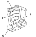
図1aおよび図1bにはロボットグリッパの透視図が示されており、図1cにはその縦断面図が示されている。ロボットグリッパはその上端部に固定フランジ1を備えており、グリッパはこの固定フランジを介して、4つの図示されていない固定ピンにより、やはり図示されていないロボットアームに取外し可能に固定して取り付けることができる。固定装置1と一体に結合され、ヨークとして形成されたフレーム3が設けられており、このフレームは、さらなる実施形態が示すように、機械的な端面支持部としても、機械的なガイド要素としても、関節ユニットとしても働く。ヨーク状に形成されたフレーム3で囲まれる空間4内には、蛇腹状に形成されたアクチュエータ要素5が設けられており、このアクチュエータ要素は、曲げ弾性を有する壁7によって内部ボリューム6を取り囲んでいる。曲げ弾性をもつように形成された壁は、好ましくはロボットグリッパの他のすべてのコンポーネントと同様に同じ材料から製造され、ただし壁厚は非常に薄く、縦断面(図1cを参照)が波形に形成された壁形状7を有しており、その波形がリニア軸Aを規定し、蛇腹状に形成されたアクチュエータ要素は、ボリューム6が媒体で、好ましくは圧縮空気で満たされる過程で、このリニア軸に沿って拡張することができる。そのために、蛇腹状に形成されたアクチュエータ要素5は接続導管8を備えており、この接続導管を介して、蛇腹状に形成されたアクチュエータ要素5のボリューム6内に圧縮空気を送り込むことができる。
1a and 1b show perspective views of the robot gripper, and FIG. 1c shows a longitudinal sectional view thereof. The robot gripper has a
図1cでは、蛇腹状に形成されたアクチュエータ要素の片側がフレーム3と結合され、蛇腹状に形成されたアクチュエータ要素5のもう一方の端部が力伝達要素9と結合されていることが分かる。
In FIG. 1c, it can be seen that one side of the accordion-shaped actuator element is coupled to the
接続導管8を介して圧縮空気が蛇腹状に形成されたアクチュエータ要素5のボリューム6内に送り込まれると、アクチュエータ要素5が、図1cの表示に従ってリニア軸Aに沿って下方に拡張する。この場合、フレーム3の上部は、リニア軸Aに沿って拡張するアクチュエータ要素5のための機械的な端面支持部として働く。
When compressed air is fed into the
力伝達要素9は、両側に2つのガイド溝10を備えており、拡張するアクチュエータ要素5によって同様に直線的にリニア軸Aに沿って下方に移動し、その際、力伝達要素9は、両脇のフレーム3との2つの境界面11により、強制的にリニア軸Aに沿って案内される。
The force transmission element 9 is provided with two
さらにフレーム3は、2つの関節ユニット12を備えており、この関節ユニットの周りに、図1cの図平面と垂直に交差する回転軸Dに沿って設けられた連結部13が、旋回可能に支持されている。連結部13は、フレーム側に設けられた関節形状12をほぼ完全に取り囲んで、フレーム側の関節区間12と共に、封じ込められた関節ユニットを形成しており、関節ユニット側からこれを外すことはできない。さらに連結部13はそれぞれ、力伝達要素9のガイド溝10内に突き出たガイド輪郭14を有しており、これにより連結部13は、力伝達要素9がリニア軸に沿って下方に垂直に変位すると、それぞれ回転軸Dの周りを側方に外側へ旋回する。
Further, the
連結部13には、必要および使用に応じて、相応に形成されたグリッパジョー要素(図1には図示されず)を取り付けることができる。
A correspondingly formed gripper jaw element (not shown in FIG. 1) can be attached to the connecting
一方、アクチュエータ要素5のボリューム6が排気されると、アクチュエータ要素5の曲げ弾性を有する壁にある復元弾力が、力伝達要素9をリニア軸Aに沿って戻し、つまり図1cでの表示に従えば上方に移動させ、それにより、最終的に連結部を一緒に回転軸Dの周りで旋回させる。この工程は、2つのグリッパジョーの間に配置された対象物を掴むことに相当する。
On the other hand, when the
図2aおよび図2bには、図1に描かれたロボットグリッパの構造型式に基づくロボットグリッパの透視図が示されているが、ただしグリッパジョー15を備えており、このグリッパジョーは、それぞれの連結部13と一体に製造してもよく、あるいは既に上で述べたように後から連結部13に取り付けてもよい。
FIGS. 2a and 2b show perspective views of a robot gripper based on the robot gripper structural type depicted in FIG. 1, but with
図3aには、ロボットグリッパのさらなる変形形態の透視図が示されており、図3bには、図3aに対応する縦断面図が示されている。ロボットグリッパのさらなる変形形態の縦断面図を示す図3bを参照すると、固定機構1、フレーム3、アクチュエータ要素5、ならびにレバーアーム16とグリッパフィンガー17から成るグリッパジョー18が、一体に製造されていることが分かる。図1による変形実施形態とは異なり、蛇腹状に形成されたアクチュエータ要素が対称的に、中心にあるフレーム区間31で支持されており、このフレーム区間によって、互いに連絡している2つの部分ボリューム61、62に区分されている。図3bによる縦断面図から、接続導管8を介して部分ボリューム61、62に圧縮空気を満たすと、蛇腹状に形成された両方のアクチュエータ要素半体が、破線で記されたリニア軸Bに沿って、それぞれ矢印方向に外側に拡張されることが分かる。蛇腹状に形成されたアクチュエータ要素区間の、それぞれフレーム区間31とは反対側の端部が、グリッパジョー18のレバーアーム16と固定的に結合されており、このレバーアームはそれぞれフィルム関節19を介してグリッパフィンガー17と結合されている。部分アクチュエータ要素がそれぞれ上述のように外側に移動すると、両側のグリッパフィンガー17が互いに向かって移動し、このようにしてグリップ工程をコントロールすることができる。一方、内部の部分ボリューム61、62から空気が抜かれると、波形に形成された部分アクチュエータ要素の曲げ弾性を有する壁の内部で働く復元弾力により、両方のグリッパフィンガー17が開く。
FIG. 3a shows a perspective view of a further variant of the robot gripper, and FIG. 3b shows a longitudinal section corresponding to FIG. 3a. With reference to FIG. 3b, which shows a longitudinal section of a further variant of the robot gripper, the
最後に、グリッパフィンガー17が開く力および速度は、蛇腹状に形成されたアクチュエータ要素5の波形に形成された壁材の自己弾性復元力と、フィルムヒンジとして形成された関節領域の自己弾性復元力とに依存する。蛇腹状に形成されたアクチュエータ要素5の自己弾性力だけだと、いくつかの適用例の場合には、グリッパフィンガー17の間隔が開く速度が遅すぎるかもしれず、その力が弱すぎるかもしれず、かつ定義された最終ストッパのところまで行かないかもしれないので、さらなる有利な実施形態ではこのために、さらにバネ要素19の形の力生成要素を設けている。このように形成されたロボットグリッパが図4aから図4cに示されている。バネ要素19の片側は、グリッパフィンガー17のグリッパ機能を損なうことなく、図中の左側のグリッパジョー18と固定して一体に結合されている。バネ要素のもう一方の端部は固定されずに延びており、加えて突っ張り要素20を備えている。図4bの透視図によれば、バネ要素19がもう1つのグリッパジョー内の孔部21を通って突き出ていることが分かる。孔部21には外れ止めが設けられており、バネ要素19が突っ張って、両方のグリッパジョー18の間でグリッパフィンガー17の間隔を広げる要素として働く場合(図4cを参照)、この外れ止め内に、突っ張り要素20に設けられホゾ状に形成された固定用突起22が噛み合う。したがって、バネ要素19によって前述のように準備された予備張力は、接続導管8を通って媒体が相応に排出された後に蛇腹状に形成されたアクチュエータ要素5がより素早く圧縮状態に戻るのに役立つ。これに加えて、バネ要素19は、グリッパジョー18の上部の側面23を、フレーム側に設けられ、グリッパジョーの定義された開いた位置を保証する最終ストッパ24に押し付けることができる。他方で、フレーム3は、閉じ工程の場合にグリッパジョーの移動を制限するためにストッパ25を備えており、閉じる場合には、グリッパジョー18の外部輪郭26がそれぞれこのストッパにぶつかる。
Finally, the force and speed at which the
上述のグリッパシステムは、素早く、如何なる組立もなく、グリッパのそれぞれの使命に合わせて直接CADデータセットから製造することができる。したがって、システムの総費用は、市販のシステムに比べて非常に安価になる。もちろんさらなる代替グリッパ構造を積層造形法によって製造することも可能であり、本発明の考え方は、上記の例示的実施形態だけに制限されるものではない。 The gripper system described above can be manufactured directly from a CAD data set for each of the gripper's missions quickly and without any assembly. Thus, the total cost of the system is very cheap compared to a commercial system. Of course, further alternative gripper structures can be produced by additive manufacturing, and the inventive concept is not limited to the exemplary embodiments described above.
1 固定フランジ
2 固定開口部
3 フレーム
4 内部空間
5 蛇腹状のアクチュエータ要素
6 ボリューム
61、62 部分ボリューム
7 壁
8 接続導管
9 力伝達要素
10 溝状の凹部
11 ガイド壁区間
12 関節
13 連結部
14 ガイド輪郭
15 グリッパジョー
16 レバーアーム
17 グリッパフィンガー
18 グリッパジョー
19 バネ要素
20 突っ張り要素
21 外れ止め(孔部)
22 固定用突起
23 側面
24 最終ストッパ
25 ストッパ
26 外部輪郭
1 Fixed flange
2 Fixed opening
3 frames
4 Internal space
5 bellows-like actuator element
6 volume
61, 62 Partial volume
7 walls
8 Connecting conduit
9 Power transmission elements
10 Groove-shaped recess
11 Guide wall section
12 joints
13 Connecting part
14 Guide contour
15 Gripper jaw
16 Lever arm
17 Gripper fingers
18 Gripper jaw
19 Spring element
20 Strut elements
21 Stopper (hole)
22 Fixing protrusion
23 Side
24 Final stopper
25 Stopper
26 External contour
Claims (12)
少なくとも前記固定フランジ(1)、フレーム(3)、およびアクチュエータ要素(5)が、積層造形法を使用して一体に製造されること、ならびに
前記アクチュエータ要素(5)が、蛇腹状に形成されており、少なくとも1つの開口部を介して媒体を満たすことができるボリューム(6)を含んでおり、前記ボリュームは、媒体を満たすと、アクチュエータ要素(5)の蛇腹状の形成によって規定されるリニア軸(A、B)に沿って拡張させることができ、ボリュームを空にすると、リニア軸に沿って逆方向に収縮させることができることを特徴とするロボットグリッパ。 A fixed flange (1) for removably attaching to the robot manipulator arm and supported in the frame (3) and indirectly or at least two gripper jaws (15, 18) via at least one joint unit (12) In a robot gripper comprising at least one actuator element (5) actuated directly,
At least the fixing flange (1), the frame (3), and the actuator element (5) are manufactured integrally using an additive manufacturing method, and the actuator element (5) is formed in a bellows shape. And includes a volume (6) capable of filling the medium through at least one opening, said volume being defined by a bellows-shaped formation of the actuator element (5) when filled with the medium A robot gripper which can be expanded along (A, B) and can be contracted in the opposite direction along the linear axis when the volume is emptied.
前記力伝達要素(9)が、それぞれ関節(12)を介して回転軸の周りを旋回可能にフレーム(3)と結合された2つの連結部(13)と、それぞれ1つのガイド輪郭(14)を介して結合可能であること、ならびに
前記連結部(13)のそれぞれにアーム状のグリッパジョー(15)が1つずつ取り付けられているか、または前記連結部(13)のそれぞれがグリッパジョー(15)と一体に結合されていることを特徴とする請求項1から3のいずれか一項に記載のロボットグリッパ。 The actuator element (5) is coupled to the frame (3) as a mechanical end face support on one side and to the force transmission element (9) linearly guided by the frame (3) on the other side. about,
The force transmission element (9) has two connecting parts (13) coupled to the frame (3) so as to be able to turn around a rotation axis via joints (12), respectively, and one guide contour (14). And one arm-like gripper jaw (15) is attached to each of the connecting portions (13), or each of the connecting portions (13) is attached to the gripper jaws (15). The robot gripper according to any one of claims 1 to 3, wherein the robot gripper is integrally coupled to the robot gripper.
前記両方の部分ボリューム(61、62)が、それぞれフレーム区間(31)とは反対の側でレバーアーム(16)を操作するように結合しており、前記レバーアームが、フレーム(3)と結合された関節ユニット(12’)を介してグリッパジョー(18)に一体に接続され、前記関節ユニット(12’)で旋回可能に支持されていることを特徴とする請求項1から3のいずれか一項に記載のロボットグリッパ。 Two partial volumes (61, 62) in which the actuator elements (5) formed in a bellows shape are arranged symmetrically in the frame section (31) and communicate with each other through the frame section (31) The two partial volumes are filled with a medium and are expanded in opposite directions along a common linear axis (B), and both the partial volumes (61, 62) are each a frame. The lever arm (16) is coupled to be operated on the side opposite to the section (31), and the lever arm is connected to the gripper jaw (12 ') via the joint unit (12') coupled to the frame (3). 18. The robot gripper according to claim 1, wherein the robot gripper is integrally connected to 18, and is supported by the joint unit (12 ′) so as to be able to turn.
フォトリソグラフィー法を用いたラピッドプロトタイピング、
液体浴からの層状の硬化による光重合、
粉末層の層状の敷きつめおよび固化、
粉末結合体内への接着剤の層状の射出、
金属粉末中でのエネルギービーム堆積法、
プラスチック押出成形技術、
のいずれか1つの積層造形法に、製造パラメータとして提供可能であることを特徴とする請求項1から7のいずれか一項に記載のロボットグリッパ。 The robot gripper to be manufactured is presented as a CAD data set based on shape and size, and the data set is of the following type: rapid prototyping using photolithographic methods,
Photopolymerization by layered curing from a liquid bath,
Layered paving and solidification of powder layer,
Layered injection of adhesive into the powder binder,
Energy beam deposition in metal powder,
Plastic extrusion technology,
The robot gripper according to any one of claims 1 to 7, wherein the robot gripper can be provided as a manufacturing parameter to any one of the additive manufacturing methods.
前記バネ要素が、弾性力に抗して、自由端であるバネ要素端部で、ロボットグリッパの突っ張り支持輪郭に軸架可能であることを特徴とする請求項9に記載のロボットグリッパ。 The spring element has two opposing spring element ends, one of the spring element ends is integrally coupled to the robot gripper, and the other spring element end is a free end; The robot gripper according to claim 9, wherein the spring element can be pivotally mounted on a tension support contour of the robot gripper at a spring element end which is a free end against an elastic force.
Applications Claiming Priority (3)
| Application Number | Priority Date | Filing Date | Title |
|---|---|---|---|
| DE102005046160.3 | 2005-09-27 | ||
| DE102005046160A DE102005046160C5 (en) | 2005-09-27 | 2005-09-27 | Robotic gripper and method for its manufacture |
| PCT/EP2006/008555 WO2007036280A1 (en) | 2005-09-27 | 2006-09-01 | Robot gripper and method for its manufacture |
Publications (2)
| Publication Number | Publication Date |
|---|---|
| JP2009509777A JP2009509777A (en) | 2009-03-12 |
| JP5276441B2 true JP5276441B2 (en) | 2013-08-28 |
Family
ID=37467595
Family Applications (1)
| Application Number | Title | Priority Date | Filing Date |
|---|---|---|---|
| JP2008531561A Expired - Fee Related JP5276441B2 (en) | 2005-09-27 | 2006-09-01 | Robot gripper |
Country Status (6)
| Country | Link |
|---|---|
| US (1) | US8011708B2 (en) |
| EP (1) | EP1943064B1 (en) |
| JP (1) | JP5276441B2 (en) |
| AT (1) | ATE435725T1 (en) |
| DE (2) | DE102005046160C5 (en) |
| WO (1) | WO2007036280A1 (en) |
Families Citing this family (64)
| Publication number | Priority date | Publication date | Assignee | Title |
|---|---|---|---|---|
| DE102007022122B4 (en) | 2007-05-11 | 2019-07-11 | Deutsches Zentrum für Luft- und Raumfahrt e.V. | Gripping device for a surgery robot arrangement |
| DE102007030036A1 (en) * | 2007-06-29 | 2009-01-02 | Fraunhofer-Gesellschaft zur Förderung der angewandten Forschung e.V. | Gripping tool, has multiple drives including hollow inflatable body inflated under pressure during discharging of fluid e.g. gas, such that force for performing gripping movement is directly exercised or via power transmission mechanism |
| SE530898C2 (en) * | 2007-12-19 | 2008-10-14 | Autolabel Ab | Device for tools and method for making them |
| CN101926009B (en) * | 2008-01-25 | 2012-01-25 | 应用材料股份有限公司 | Automated solar cell electrical connection apparatus |
| DE102008026534B4 (en) | 2008-06-03 | 2012-04-19 | Fraunhofer-Gesellschaft zur Förderung der angewandten Forschung e.V. | Device and method for overpressure detection in a working volume of an actuator |
| CN102186638B (en) * | 2008-08-29 | 2016-03-02 | Abb研究有限公司 | In the compliant device of the instrument of the arm end of industrial robot |
| US8317241B2 (en) * | 2009-02-06 | 2012-11-27 | Dean Ehnes | Harsh environment robot end effector |
| DE202009002746U1 (en) | 2009-02-26 | 2009-05-07 | Fraunhofer-Gesellschaft zur Förderung der angewandten Forschung e.V. | Robot gripper |
| DE102009015977A1 (en) | 2009-03-26 | 2010-09-30 | Festo Ag & Co. Kg | driving device |
| DE102009015975B4 (en) * | 2009-03-26 | 2012-01-05 | Festo Ag & Co. Kg | Fluid technical device, in particular gripper device |
| DE102009021558B4 (en) * | 2009-05-14 | 2017-12-07 | Zahoransky Ag | tongs |
| EP2335884B1 (en) | 2009-12-15 | 2012-09-05 | FESTO AG & Co. KG | Fluid-operated manipulator |
| US8464412B2 (en) * | 2010-01-19 | 2013-06-18 | Cheng Uei Precision Industry Co., Ltd. | Clutching jig |
| DE102010035561B3 (en) * | 2010-08-26 | 2012-01-19 | Wsengineering Gmbh & Co.Kg | Tool holder with evasive mechanism and method for its production |
| DE102011011942B4 (en) | 2011-02-22 | 2014-03-27 | Fraunhofer-Gesellschaft zur Förderung der angewandten Forschung e.V. | Robot gripper |
| ES2428969T3 (en) * | 2011-05-12 | 2013-11-12 | Ulma Packaging Technological Center, S. Coop | Claw to capture and transport food products |
| DE102011107580B4 (en) | 2011-07-16 | 2015-02-05 | Festo Ag & Co. Kg | Bellows and method of making a bellows |
| DE102011080820A1 (en) * | 2011-08-11 | 2013-02-14 | Siemens Aktiengesellschaft | Method for producing a machine element and machine element, in particular shaft bearings |
| DE102012208185B4 (en) * | 2011-09-16 | 2015-05-13 | Schunk Gmbh & Co. Kg Spann- Und Greiftechnik | hole gripper |
| JP2013123785A (en) * | 2011-12-16 | 2013-06-24 | Seiko Epson Corp | Robot hand and robot |
| DE102012100916A1 (en) * | 2012-02-03 | 2013-08-08 | Asm Assembly Systems Gmbh & Co. Kg | Single-piece objects gripper device for use in mounting machine for mounting electronic components on printed circuit board, has gripper element actively connected with pliers element for gripping objects during actuation of membrane |
| US8951303B2 (en) | 2012-06-11 | 2015-02-10 | Ut-Battelle, Llc | Freeform fluidics |
| DE102012219137A1 (en) * | 2012-10-19 | 2014-04-24 | Schunk Gmbh & Co. Kg Spann- Und Greiftechnik | Method for producing customer-specific components |
| DE202012012083U1 (en) * | 2012-12-18 | 2013-01-16 | Fipa Gmbh | Gripper, in particular pneumatically operated gripper |
| KR101471350B1 (en) * | 2013-02-26 | 2014-12-10 | 엄기영 | Clip for jig |
| DE102014207736B4 (en) * | 2014-04-24 | 2018-09-13 | Deutsches Elektronen-Synchrotron Desy | Sample gripping device and measuring device with a sample gripping device |
| DE102014210331A1 (en) | 2014-06-02 | 2015-12-03 | Kuka Systems Gmbh | Jaw security with tongue and groove for MRK |
| DE102014210330B4 (en) | 2014-06-02 | 2016-08-04 | Kuka Systems Gmbh | Gripper jaw assurance |
| DE102015204486B4 (en) * | 2015-03-12 | 2022-08-04 | Fraunhofer-Gesellschaft zur Förderung der angewandten Forschung e.V. | surgical instrument |
| DE102015205259B4 (en) | 2015-03-24 | 2019-02-21 | Kuka Systems Gmbh | Method and system for aligning components |
| US9505135B1 (en) | 2015-08-28 | 2016-11-29 | Tyco Electronics Corporation | Gripper with conformal spring fingers |
| DE102015114556A1 (en) | 2015-09-01 | 2017-03-02 | Röhm Gmbh | Gripper and method for making a gripper |
| DE102015114580A1 (en) * | 2015-09-01 | 2017-03-02 | Röhm Gmbh | Gripper and method for making a gripper |
| DE102015114710A1 (en) * | 2015-09-03 | 2017-03-09 | Röhm Gmbh | Clamping jaw and method for producing a clamping jaw |
| EP3243608B1 (en) * | 2016-05-09 | 2022-04-06 | J. Schmalz GmbH | Method for monitoring the functioning states of a pressure driven actuator and pressure driven actuator |
| EP3367102A1 (en) * | 2017-02-23 | 2018-08-29 | Roche Diagnostics GmbH | Gripping device and sample container processing system |
| FR3063668B1 (en) * | 2017-03-07 | 2019-03-15 | Commissariat A L'energie Atomique Et Aux Energies Alternatives | CLIP-TYPE GRIPPING DEVICE AND SYSTEM COMPRISING SUCH DEVICES |
| CN107009384A (en) * | 2017-05-26 | 2017-08-04 | 云南电网有限责任公司电力科学研究院 | A kind of clamping device and manipulator |
| US10875195B2 (en) | 2017-06-22 | 2020-12-29 | Gordon T. Zitting | Robot gripper |
| JP7035354B2 (en) * | 2017-07-20 | 2022-03-15 | 株式会社アイシン | Gripping hand |
| JP7035355B2 (en) * | 2017-07-20 | 2022-03-15 | 株式会社アイシン | Gripping device |
| JP7137940B2 (en) * | 2017-08-10 | 2022-09-15 | 株式会社京都製作所 | gripping device |
| US20200276752A1 (en) * | 2017-09-22 | 2020-09-03 | Konica Minolta, Inc. | Resin composition, method for manufacturing three-dimensional object using resin composition, three-dimensional object, and object-gripping attachment, and industrial robot using object-gripping attachment |
| FR3071424B1 (en) * | 2017-09-25 | 2020-01-10 | Commissariat A L'energie Atomique Et Aux Energies Alternatives | MONOBLOCK STRUCTURAL MICRO-PLIERS |
| US10118299B1 (en) | 2018-02-23 | 2018-11-06 | Yak Mat, LLC. | Rod puller |
| EP3530415A1 (en) * | 2018-02-27 | 2019-08-28 | Piab Ab | Vacuum powered gripper |
| JP6991395B2 (en) * | 2018-10-30 | 2022-01-12 | シーメンス アクチエンゲゼルシヤフト | Gripping fingers and adaptive gripping devices with curved spacer members |
| CN109368249A (en) * | 2018-11-07 | 2019-02-22 | 天津中环领先材料技术有限公司 | A kind of grinding cleaning machine automatic charging device |
| CN109732582B (en) * | 2019-01-18 | 2022-01-28 | 哈尔滨工业大学 | Soft robot camera carrying device and method based on outer side stay wire |
| DE102019102913A1 (en) * | 2019-02-06 | 2020-08-06 | Hochschule Offenburg | Method for producing a robot element, in particular a gripper, by means of 3D printing |
| DE102019003714B4 (en) * | 2019-05-25 | 2021-05-06 | Festo Se & Co. Kg | One-piece molded gripping device with support and bending arms |
| DE102019119125A1 (en) | 2019-07-15 | 2021-01-21 | Festo Se & Co. Kg | Gripping device |
| US11187252B2 (en) * | 2019-10-03 | 2021-11-30 | Universal City Studios Llc | Mechanically programmable closed fluid actuation system |
| US11530052B1 (en) | 2020-02-17 | 2022-12-20 | Amazon Technologies, Inc. | Systems and methods for automated ground handling of aerial vehicles |
| IT202000005257A1 (en) * | 2020-03-11 | 2021-09-11 | Aea Srl | GRIPPING DEVICE |
| US11597092B1 (en) * | 2020-03-26 | 2023-03-07 | Amazon Technologies, Ine. | End-of-arm tool with a load cell |
| CN111590627B (en) * | 2020-05-29 | 2022-04-22 | 苏州天准科技股份有限公司 | Clamping jaw device |
| US11534924B1 (en) | 2020-07-21 | 2022-12-27 | Amazon Technologies, Inc. | Systems and methods for generating models for automated handling of vehicles |
| US11534915B1 (en) | 2020-08-05 | 2022-12-27 | Amazon Technologies, Inc. | Determining vehicle integrity based on observed behavior during predetermined manipulations |
| CN112440294A (en) * | 2020-11-16 | 2021-03-05 | 泉州市旋吉机械产品有限公司 | Full-automatic manufacturing assembly line of manipulator auxiliary connector |
| CN112512291B (en) * | 2020-11-27 | 2022-08-12 | 江苏硕伯亚智能科技有限公司 | Position adjusting device for electronic component maintenance |
| US11833683B2 (en) * | 2020-12-26 | 2023-12-05 | Allen P Biehle | Item gripping device with intrinsic item orienting attributes |
| DE102021118044A1 (en) | 2021-07-13 | 2023-01-19 | layer manufactory GmbH | Driving a gripper by means of a suction cup |
| DE102021005730B4 (en) | 2021-11-19 | 2023-01-19 | Mercedes-Benz Group AG | gripper unit |
Family Cites Families (15)
| Publication number | Priority date | Publication date | Assignee | Title |
|---|---|---|---|---|
| JPS61124708A (en) * | 1984-11-19 | 1986-06-12 | 株式会社 岩本製作所 | Chuck for gripping mechanism |
| JPS6253982U (en) * | 1985-09-19 | 1987-04-03 | ||
| IT1211462B (en) * | 1986-04-21 | 1989-11-03 | Silvestrini Jesus Antonio E Ba | PISTOL HEAD OF FRUITS SUCH AS PEACHES |
| JPH02134356U (en) * | 1989-04-13 | 1990-11-07 | ||
| US5046773A (en) * | 1990-01-02 | 1991-09-10 | Hewlett-Packard Company | Micro-gripper assembly |
| ATE134554T1 (en) * | 1991-09-16 | 1996-03-15 | Sig Schweiz Industrieges | GRIPPER FOR A MANIPULATOR |
| JPH05293778A (en) * | 1992-04-17 | 1993-11-09 | Seiko Instr Inc | Microgripper |
| US5529359A (en) * | 1994-04-22 | 1996-06-25 | Borcea; Nicky | Cripper assembly with improved synchronous transmission |
| DE4432253A1 (en) * | 1994-09-10 | 1996-03-14 | Gerhard Prof Dr Ing Boegelsack | Motion and power transmission mechanism esp. for miniaturisation |
| US5637200A (en) * | 1995-02-08 | 1997-06-10 | Nobler Technologies, Inc. | Compact disk locking apparatus |
| FR2739049B1 (en) * | 1995-09-25 | 1997-12-12 | Gerplant Automation | FLUID-HANDLED GRIPPER |
| DE19701078C1 (en) * | 1997-01-15 | 1998-02-05 | Ikm Inst Fuer Kunststoffe Im M | Thermoplastics-shaping tool production |
| DE10007711C1 (en) * | 2000-02-19 | 2001-08-16 | Daimler Chrysler Ag | Apparatus for sintering a powder used in rapid prototyping process comprises device for producing laser beam, device for determining powder temperature, device for regulating laser beam, and device for compensating position-dependent errors |
| DE10235427A1 (en) * | 2002-08-02 | 2004-02-12 | Eos Gmbh Electro Optical Systems | Device for producing three-dimensional objects under the action of electromagnetic or particle radiation has a switching unit for switching the radiation between the construction regions so that each construction region is irradiated |
| DE10340052B4 (en) * | 2003-08-28 | 2006-02-09 | Dieter Ronsdorf | Method for producing flexible functional clamping elements |
-
2005
- 2005-09-27 DE DE102005046160A patent/DE102005046160C5/en active Active
-
2006
- 2006-09-01 WO PCT/EP2006/008555 patent/WO2007036280A1/en active Application Filing
- 2006-09-01 AT AT06791783T patent/ATE435725T1/en active
- 2006-09-01 DE DE502006004205T patent/DE502006004205D1/en not_active Expired - Fee Related
- 2006-09-01 JP JP2008531561A patent/JP5276441B2/en not_active Expired - Fee Related
- 2006-09-01 US US11/992,542 patent/US8011708B2/en not_active Expired - Fee Related
- 2006-09-01 EP EP06791783A patent/EP1943064B1/en not_active Not-in-force
Also Published As
| Publication number | Publication date |
|---|---|
| US20090108605A1 (en) | 2009-04-30 |
| ATE435725T1 (en) | 2009-07-15 |
| WO2007036280A1 (en) | 2007-04-05 |
| DE502006004205D1 (en) | 2009-08-20 |
| DE102005046160B3 (en) | 2007-03-22 |
| JP2009509777A (en) | 2009-03-12 |
| EP1943064A1 (en) | 2008-07-16 |
| DE102005046160C5 (en) | 2008-12-24 |
| EP1943064B1 (en) | 2009-07-08 |
| US8011708B2 (en) | 2011-09-06 |
Similar Documents
| Publication | Publication Date | Title |
|---|---|---|
| JP5276441B2 (en) | Robot gripper | |
| US10219919B2 (en) | Multi-grasp prosthetic hand | |
| US20190291344A1 (en) | Techniques for applying a peel operation during additive fabrication and related systems and methods | |
| Choi et al. | Passive compliant wafer stage for single-step nano-imprint lithography | |
| Wakimoto et al. | Miniature pneumatic curling rubber actuator generating bidirectional motion with one air-supply tube | |
| Pagoli et al. | A soft robotic gripper with an active palm and reconfigurable fingers for fully dexterous in-hand manipulation | |
| JP6853226B2 (en) | Gripping device for robots | |
| Evjemo et al. | Additive manufacturing by robot manipulator: An overview of the state-of-the-art and proof-of-concept results | |
| JP2010532266A (en) | Ring insertion crimping device for a fixture with a rod having a ring crimped to the rod | |
| Won et al. | Rapid prototyping of robotic systems | |
| Nguyen et al. | Modeling of piezo-actuated stick-slip micro-drives: An overview | |
| JP6559180B2 (en) | Robot hand, robot apparatus, robot hand control method, control program, and recording medium | |
| Jain et al. | Development of piezoelectric actuator based compliant micro gripper for robotic peg-in-hole assembly | |
| JP2023025171A (en) | Roller interchange device, roller interchange assembly, and composite lay-up device | |
| Probst et al. | Design of an advanced microassembly system for the automated assembly of bio-microrobots | |
| Ma et al. | Design and control of an end-effector module for industrial finishing applications | |
| Li et al. | Kinematic design of a novel 3-DOF compliant parallel manipulator for nanomanipulation | |
| US7124499B2 (en) | Apparatus for installing a length of wire | |
| JP2000043150A (en) | Photo fabrication method, apparatus therefor and composite machine component | |
| Chung et al. | Development of precision robot manipulator using flexure hinge mechanism | |
| JP4073061B2 (en) | Precision positioning device using impact force by piezoelectric element | |
| Li et al. | Novel design of a 3-PUU spatial compliant parallel micromanipulator for nanomanipulation | |
| JP2023183213A (en) | Mechanical impedance estimation method for parallel link mechanism | |
| Cutkosky et al. | A high force miniature gripper fabricated via shape deposition manufacturing | |
| Liu et al. | Origami-inspired Bi-directional Actuator with Orthogonal Actuation |
Legal Events
| Date | Code | Title | Description |
|---|---|---|---|
| A621 | Written request for application examination |
Free format text: JAPANESE INTERMEDIATE CODE: A621 Effective date: 20090406 |
|
| A977 | Report on retrieval |
Free format text: JAPANESE INTERMEDIATE CODE: A971007 Effective date: 20110624 |
|
| A131 | Notification of reasons for refusal |
Free format text: JAPANESE INTERMEDIATE CODE: A131 Effective date: 20110628 |
|
| A521 | Request for written amendment filed |
Free format text: JAPANESE INTERMEDIATE CODE: A523 Effective date: 20110928 |
|
| A131 | Notification of reasons for refusal |
Free format text: JAPANESE INTERMEDIATE CODE: A131 Effective date: 20120117 |
|
| A521 | Request for written amendment filed |
Free format text: JAPANESE INTERMEDIATE CODE: A523 Effective date: 20120416 |
|
| A131 | Notification of reasons for refusal |
Free format text: JAPANESE INTERMEDIATE CODE: A131 Effective date: 20120911 |
|
| A521 | Request for written amendment filed |
Free format text: JAPANESE INTERMEDIATE CODE: A523 Effective date: 20121206 |
|
| TRDD | Decision of grant or rejection written | ||
| A01 | Written decision to grant a patent or to grant a registration (utility model) |
Free format text: JAPANESE INTERMEDIATE CODE: A01 Effective date: 20130423 |
|
| A61 | First payment of annual fees (during grant procedure) |
Free format text: JAPANESE INTERMEDIATE CODE: A61 Effective date: 20130517 |
|
| R150 | Certificate of patent or registration of utility model |
Free format text: JAPANESE INTERMEDIATE CODE: R150 Ref document number: 5276441 Country of ref document: JP Free format text: JAPANESE INTERMEDIATE CODE: R150 |
|
| R250 | Receipt of annual fees |
Free format text: JAPANESE INTERMEDIATE CODE: R250 |
|
| R250 | Receipt of annual fees |
Free format text: JAPANESE INTERMEDIATE CODE: R250 |
|
| R250 | Receipt of annual fees |
Free format text: JAPANESE INTERMEDIATE CODE: R250 |
|
| R250 | Receipt of annual fees |
Free format text: JAPANESE INTERMEDIATE CODE: R250 |
|
| R250 | Receipt of annual fees |
Free format text: JAPANESE INTERMEDIATE CODE: R250 |
|
| R250 | Receipt of annual fees |
Free format text: JAPANESE INTERMEDIATE CODE: R250 |
|
| R250 | Receipt of annual fees |
Free format text: JAPANESE INTERMEDIATE CODE: R250 |
|
| LAPS | Cancellation because of no payment of annual fees |