JP5276107B2 - Method of firing from green body to porous ceramic article - Google Patents
Method of firing from green body to porous ceramic article Download PDFInfo
- Publication number
- JP5276107B2 JP5276107B2 JP2010522960A JP2010522960A JP5276107B2 JP 5276107 B2 JP5276107 B2 JP 5276107B2 JP 2010522960 A JP2010522960 A JP 2010522960A JP 2010522960 A JP2010522960 A JP 2010522960A JP 5276107 B2 JP5276107 B2 JP 5276107B2
- Authority
- JP
- Japan
- Prior art keywords
- temperature
- peak
- firing
- ceramic
- aging
- Prior art date
- Legal status (The legal status is an assumption and is not a legal conclusion. Google has not performed a legal analysis and makes no representation as to the accuracy of the status listed.)
- Expired - Fee Related
Links
Images


Classifications
-
- C—CHEMISTRY; METALLURGY
- C04—CEMENTS; CONCRETE; ARTIFICIAL STONE; CERAMICS; REFRACTORIES
- C04B—LIME, MAGNESIA; SLAG; CEMENTS; COMPOSITIONS THEREOF, e.g. MORTARS, CONCRETE OR LIKE BUILDING MATERIALS; ARTIFICIAL STONE; CERAMICS; REFRACTORIES; TREATMENT OF NATURAL STONE
- C04B35/00—Shaped ceramic products characterised by their composition; Ceramics compositions; Processing powders of inorganic compounds preparatory to the manufacturing of ceramic products
- C04B35/01—Shaped ceramic products characterised by their composition; Ceramics compositions; Processing powders of inorganic compounds preparatory to the manufacturing of ceramic products based on oxide ceramics
- C04B35/16—Shaped ceramic products characterised by their composition; Ceramics compositions; Processing powders of inorganic compounds preparatory to the manufacturing of ceramic products based on oxide ceramics based on silicates other than clay
- C04B35/18—Shaped ceramic products characterised by their composition; Ceramics compositions; Processing powders of inorganic compounds preparatory to the manufacturing of ceramic products based on oxide ceramics based on silicates other than clay rich in aluminium oxide
- C04B35/195—Alkaline earth aluminosilicates, e.g. cordierite or anorthite
-
- B—PERFORMING OPERATIONS; TRANSPORTING
- B28—WORKING CEMENT, CLAY, OR STONE
- B28B—SHAPING CLAY OR OTHER CERAMIC COMPOSITIONS; SHAPING SLAG; SHAPING MIXTURES CONTAINING CEMENTITIOUS MATERIAL, e.g. PLASTER
- B28B11/00—Apparatus or processes for treating or working the shaped or preshaped articles
- B28B11/24—Apparatus or processes for treating or working the shaped or preshaped articles for curing, setting or hardening
- B28B11/243—Setting, e.g. drying, dehydrating or firing ceramic articles
-
- C—CHEMISTRY; METALLURGY
- C04—CEMENTS; CONCRETE; ARTIFICIAL STONE; CERAMICS; REFRACTORIES
- C04B—LIME, MAGNESIA; SLAG; CEMENTS; COMPOSITIONS THEREOF, e.g. MORTARS, CONCRETE OR LIKE BUILDING MATERIALS; ARTIFICIAL STONE; CERAMICS; REFRACTORIES; TREATMENT OF NATURAL STONE
- C04B35/00—Shaped ceramic products characterised by their composition; Ceramics compositions; Processing powders of inorganic compounds preparatory to the manufacturing of ceramic products
- C04B35/622—Forming processes; Processing powders of inorganic compounds preparatory to the manufacturing of ceramic products
- C04B35/64—Burning or sintering processes
-
- C—CHEMISTRY; METALLURGY
- C04—CEMENTS; CONCRETE; ARTIFICIAL STONE; CERAMICS; REFRACTORIES
- C04B—LIME, MAGNESIA; SLAG; CEMENTS; COMPOSITIONS THEREOF, e.g. MORTARS, CONCRETE OR LIKE BUILDING MATERIALS; ARTIFICIAL STONE; CERAMICS; REFRACTORIES; TREATMENT OF NATURAL STONE
- C04B38/00—Porous mortars, concrete, artificial stone or ceramic ware; Preparation thereof
-
- B—PERFORMING OPERATIONS; TRANSPORTING
- B28—WORKING CEMENT, CLAY, OR STONE
- B28B—SHAPING CLAY OR OTHER CERAMIC COMPOSITIONS; SHAPING SLAG; SHAPING MIXTURES CONTAINING CEMENTITIOUS MATERIAL, e.g. PLASTER
- B28B3/00—Producing shaped articles from the material by using presses; Presses specially adapted therefor
- B28B3/20—Producing shaped articles from the material by using presses; Presses specially adapted therefor wherein the material is extruded
- B28B2003/203—Producing shaped articles from the material by using presses; Presses specially adapted therefor wherein the material is extruded for multi-channelled structures, e.g. honeycomb structures
-
- C—CHEMISTRY; METALLURGY
- C04—CEMENTS; CONCRETE; ARTIFICIAL STONE; CERAMICS; REFRACTORIES
- C04B—LIME, MAGNESIA; SLAG; CEMENTS; COMPOSITIONS THEREOF, e.g. MORTARS, CONCRETE OR LIKE BUILDING MATERIALS; ARTIFICIAL STONE; CERAMICS; REFRACTORIES; TREATMENT OF NATURAL STONE
- C04B2235/00—Aspects relating to ceramic starting mixtures or sintered ceramic products
- C04B2235/65—Aspects relating to heat treatments of ceramic bodies such as green ceramics or pre-sintered ceramics, e.g. burning, sintering or melting processes
- C04B2235/656—Aspects relating to heat treatments of ceramic bodies such as green ceramics or pre-sintered ceramics, e.g. burning, sintering or melting processes characterised by specific heating conditions during heat treatment
- C04B2235/6562—Heating rate
-
- C—CHEMISTRY; METALLURGY
- C04—CEMENTS; CONCRETE; ARTIFICIAL STONE; CERAMICS; REFRACTORIES
- C04B—LIME, MAGNESIA; SLAG; CEMENTS; COMPOSITIONS THEREOF, e.g. MORTARS, CONCRETE OR LIKE BUILDING MATERIALS; ARTIFICIAL STONE; CERAMICS; REFRACTORIES; TREATMENT OF NATURAL STONE
- C04B2235/00—Aspects relating to ceramic starting mixtures or sintered ceramic products
- C04B2235/65—Aspects relating to heat treatments of ceramic bodies such as green ceramics or pre-sintered ceramics, e.g. burning, sintering or melting processes
- C04B2235/656—Aspects relating to heat treatments of ceramic bodies such as green ceramics or pre-sintered ceramics, e.g. burning, sintering or melting processes characterised by specific heating conditions during heat treatment
- C04B2235/6565—Cooling rate
-
- C—CHEMISTRY; METALLURGY
- C04—CEMENTS; CONCRETE; ARTIFICIAL STONE; CERAMICS; REFRACTORIES
- C04B—LIME, MAGNESIA; SLAG; CEMENTS; COMPOSITIONS THEREOF, e.g. MORTARS, CONCRETE OR LIKE BUILDING MATERIALS; ARTIFICIAL STONE; CERAMICS; REFRACTORIES; TREATMENT OF NATURAL STONE
- C04B2235/00—Aspects relating to ceramic starting mixtures or sintered ceramic products
- C04B2235/65—Aspects relating to heat treatments of ceramic bodies such as green ceramics or pre-sintered ceramics, e.g. burning, sintering or melting processes
- C04B2235/656—Aspects relating to heat treatments of ceramic bodies such as green ceramics or pre-sintered ceramics, e.g. burning, sintering or melting processes characterised by specific heating conditions during heat treatment
- C04B2235/6567—Treatment time
-
- C—CHEMISTRY; METALLURGY
- C04—CEMENTS; CONCRETE; ARTIFICIAL STONE; CERAMICS; REFRACTORIES
- C04B—LIME, MAGNESIA; SLAG; CEMENTS; COMPOSITIONS THEREOF, e.g. MORTARS, CONCRETE OR LIKE BUILDING MATERIALS; ARTIFICIAL STONE; CERAMICS; REFRACTORIES; TREATMENT OF NATURAL STONE
- C04B2235/00—Aspects relating to ceramic starting mixtures or sintered ceramic products
- C04B2235/70—Aspects relating to sintered or melt-casted ceramic products
- C04B2235/74—Physical characteristics
- C04B2235/77—Density
Landscapes
- Engineering & Computer Science (AREA)
- Chemical & Material Sciences (AREA)
- Ceramic Engineering (AREA)
- Structural Engineering (AREA)
- Manufacturing & Machinery (AREA)
- Materials Engineering (AREA)
- Organic Chemistry (AREA)
- Inorganic Chemistry (AREA)
- Mechanical Engineering (AREA)
- Filtering Materials (AREA)
- Porous Artificial Stone Or Porous Ceramic Products (AREA)
- Ceramic Products (AREA)
- Compositions Of Oxide Ceramics (AREA)
Abstract
Description
本願は、「未焼成体から多孔質セラミック物品に焼成する方法(Method of Firing Green Bodies Into Porus Ceramic Articles)」という発明の名称で2007年8月31日に出願した米国仮特許出願第60/967,219号の利益を主張するものである。 This application is a US Provisional Patent Application No. 60/967 filed Aug. 31, 2007 under the title of “Method of Firing Green Bodies Into Porus Ceramic Articles”. , 219 claims the profit.
本発明は、一般に、排気ガスの後処理の用途における使用に適するような多孔質のセラミック体の製造方法に関する。さらに詳細には、本発明は、多孔質のセラミック体における細孔分布を調節する方法に関する。 The present invention relates generally to a method for producing a porous ceramic body suitable for use in exhaust gas aftertreatment applications. More particularly, the present invention relates to a method for adjusting the pore distribution in a porous ceramic body.
多孔質のセラミック体は、排ガスの濾過用途など、さまざまな用途に用いられる。排ガスの濾過用途では、多孔質のセラミック体は、交差する多孔壁によって画成される一連の長手方向チャネルを備えており、多孔壁は剥き出しのままであるか、または酸化触媒でコーティングされうる。チャネルおよび壁は、典型的には円形または楕円形の外皮によって境界される。微粒子濾過では、チャネルは入口チャネルと出口チャネルに分けてもよく、ここで、入口チャネルは多孔質のセラミック体の出口端で塞栓され、出口チャネルはセラミック体の入口端で塞栓される。排ガスは入口チャネルの非塞栓端を通じてセラミック体に入り、多孔壁を貫通して出口チャネル内へと入り、出口チャネルの非塞栓端を通じて外に出る。多孔壁は、多孔質のセラミック体を通る排ガスの各通路を利用して、排ガスから出る所定量の微粒子を回収する。 Porous ceramic bodies are used in various applications such as exhaust gas filtration. In exhaust gas filtration applications, the porous ceramic body comprises a series of longitudinal channels defined by intersecting porous walls, which can remain bare or coated with an oxidation catalyst. Channels and walls are typically bounded by a circular or elliptical skin. In particulate filtration, the channel may be divided into an inlet channel and an outlet channel, where the inlet channel is plugged at the outlet end of the porous ceramic body and the outlet channel is plugged at the inlet end of the ceramic body. The exhaust gas enters the ceramic body through the non-embedded end of the inlet channel, passes through the porous wall, enters the outlet channel, and exits through the non-embedded end of the outlet channel. The porous wall collects a predetermined amount of fine particles from the exhaust gas by using each passage of the exhaust gas through the porous ceramic body.
多孔質のセラミック体の濾過効率は、排ガスから回収される微粒子画分に正比例する。多孔質のセラミック体からなるディーゼル微粒子フィルタは、高い濾過効率、熱耐久性のための小さい熱膨張率、小さい背圧損失のための狭い細孔分布と大きい細孔径、構造耐久性のための大きい強度、および低いコストを兼ね備えていることが理想的である。ディーゼル排ガス濾過では、コージエライトは比較的低コストの材料であり、比較的小さい熱膨張率を提供することから、セラミック材料として好まれている。 The filtration efficiency of the porous ceramic body is directly proportional to the fine particle fraction recovered from the exhaust gas. Diesel particulate filters made of a porous ceramic body of high filtration efficiency, small has the thermal expansion coefficient for thermal durability, narrow pore distribution and large pore diameter for not small back pressure loss, the structural durability it is ideal to have both a magnitude not strength, and low cost for. The diesel exhaust filtration, cordierite is relatively low-cost material, since it provides a relatively small has a thermal expansion coefficient, are preferred as the ceramic material.
本発明は、狭い細孔径分布を有する多孔質のセラミック物品を形成する方法であって、
無機成分を含んだセラミック形成原料を含む未焼成体を、第1の平均速度で初期温度からピーク温度まで加熱する工程において、前記ピーク温度が、セラミック相が形成されるよりも高温である工程と、
前記未焼成体を、第2の平均速度で前記ピーク温度から第2の温度まで冷却する工程において、前記第2の温度が、前記セラミック相が形成される温度範囲である工程と、
平均して第2の温度で、セラミック相を形成するのに十分な時間、前記未焼成体を保持することにより、多孔質のセラミック物品を形成する工程と、
を有してなる方法を開示する。ピーク温度は第2の温度よりも少なくとも5℃高い。多孔質のコージエライトの形成に適した一部の実施の形態では、ピーク温度は1430〜1440℃であり、第2の温度は1415〜1430℃であり、ピーク温度は第2の温度よりも少なくとも5℃高い。
The present invention is a method of forming a porous ceramic article having a narrow pore size distribution comprising:
In the step of heating the inorganic component green body comprising a ceramic forming raw material I containing, from an initial temperature to a peak temperature in the first average velocity, the peak temperature is higher than the ceramic phase is formed step When,
In the step of cooling the green body from the peak temperature to the second temperature at a second average rate, the second temperature is a temperature range in which the ceramic phase is formed;
Forming the porous ceramic article by holding the green body at a second temperature on average for a time sufficient to form a ceramic phase;
A method comprising: The peak temperature is at least 5 ° C. higher than the second temperature. In some embodiments suitable for the formation of porous cordierite, the peak temperature is 1430-1440 ° C., the second temperature is 1415-1430 ° C., and the peak temperature is at least 5 than the second temperature. ℃ high.
1つの態様では、多孔質のセラミック材料の物品を製造する方法が開示され、 該方法は、
無機セラミック形成成分からなる未焼成体を提供し、
前記未焼成体を、高速昇温段階およびそれに続く保持段階を含めた焼成環境に曝露することによって加熱する、
各工程を有してなり、
前記保持段階における前記焼成環境の温度が熟成温度の上限値から熟成温度の下限値の間に保たれ、
前記高速昇温段階がピーク部分を含み、前記ピーク部分における前記焼成環境の温度がピーク部分におけるすべての時点において前記熟成温度の上限値よりも大きく、
前記ピーク部分がピーク温度を含み、前記熟成温度の上限値が前記ピーク温度よりも少なくとも5℃低い。ピーク温度は、非晶質相のガラス転移温度よりも高く、セラミックの融点温度よりも低いことが好ましく、一部の実施の形態では、ピーク温度は、セラミック材料の主要固体結晶相の融点よりも約10℃以上低く、他の実施の形態では、ピーク温度は、セラミック材料の主要固体結晶相の融点よりも約10〜20℃低く、他の実施の形態では、ピーク温度は1420℃以上、1435℃以下である。一部の実施の形態では、熟成温度の上限値はピーク温度よりも少なくとも10℃低く、他の実施の形態では、ピーク温度よりも少なくとも15℃低く、一部の実施の形態では1430℃未満であり、他の実施の形態では1420℃未満である。一部の実施の形態では、保持段階における保持温度は1300 〜1430℃の間にとどまり、一部の実施の形態では1380 〜1430℃であり、一部の実施の形態では1380〜1420℃であり、他の実施の形態では1300〜1400℃であり、さらに他の実施の形態では1350〜1400℃であり、これらは、それぞれ熟成温度の下限値および上限値に対応させることができる。保持段階における焼成環境の温度は、セラミック材料の主要固体結晶相を形成するのに十分な保持時間で、熟成温度の上限値から下限値の範囲に保たれる。無機成分の1つが無機成分の最も低い融点温度を有し、高速昇温段階における焼成環境は、無機成分の最も低い融点温度で、無機成分を高速昇温段階で少なくともある程度溶融させるのに十分な時間、1つ以上の温度に保たれることが好ましい。
In one aspect, a method of manufacturing an article of porous ceramic material is disclosed, the method comprising:
Providing a green body comprising an inorganic ceramic forming component;
Heating the green body by exposing it to a firing environment including a fast heating stage followed by a holding stage;
Having each process,
The temperature of the firing environment is maintained between the lower limit of the aging temperature from the upper limit value of the aging temperature in the holding step,
The fast heating stage includes a peak portion, and the temperature of the firing environment at the peak portion is greater than the upper limit of the aging temperature at all points in the peak portion;
The peak portion includes a peak temperature, and the upper limit value of the aging temperature is at least 5 ° C. lower than the peak temperature. The peak temperature is preferably higher than the glass transition temperature of the amorphous phase and lower than the melting point temperature of the ceramic, and in some embodiments, the peak temperature is higher than the melting point of the main solid crystalline phase of the ceramic material. In other embodiments, the peak temperature is about 10-20 ° C. lower than the melting point of the main solid crystalline phase of the ceramic material, and in other embodiments, the peak temperature is greater than 1420 ° C., 1435 It is below ℃. In some embodiments, the upper limit of aging temperature is at least 10 ° C. below the peak temperature, in other embodiments at least 15 ° C. below the peak temperature, and in some embodiments below 1430 ° C. Yes, in other embodiments below 1420 ° C. In some embodiments, the holding temperature in the holding phase remains between 1300-1430 ° C., in some embodiments 1380-1430 ° C., and in some embodiments 1380-1420 ° C. In another embodiment, the temperature is 1300 to 1400 ° C., and in another embodiment, it is 1350 to 1400 ° C., and these can correspond to the lower limit value and the upper limit value of the aging temperature, respectively. The temperature of the firing environment in the holding stage is maintained within the range from the upper limit value to the lower limit value of the aging temperature with a holding time sufficient to form the main solid crystalline phase of the ceramic material. One of the inorganic components has the lowest melting point temperature of the inorganic component, and the firing environment in the fast heating stage is sufficient to melt the inorganic component at least to some extent in the fast heating stage at the lowest melting temperature of the inorganic component. Preferably, the time is maintained at one or more temperatures.
高速昇温段階における焼成環境は、好ましくは30℃/時間、さらに好ましくは50℃/時間よりも速い昇温速度で、1200℃の初期温度からピーク温度まで上昇することが好ましく、一部の実施の形態では75℃/時間より速く、他の実施の形態では100℃/時間より速く、他の実施の形態では120℃/時間より速いことが好ましい。 The firing environment in the high temperature heating stage preferably rises from an initial temperature of 1200 ° C. to a peak temperature, preferably at a heating rate faster than 30 ° C./hour, more preferably 50 ° C./hour. It is preferably faster than 75 ° C./hour in this embodiment, faster than 100 ° C./hour in other embodiments, and faster than 120 ° C./hour in other embodiments.
一部の実施の形態では、高速昇温段階における焼成環境は、1200℃の初期温度からピーク温度まで5時間未満で上昇し、他の実施の形態では4時間未満、他の実施の形態では3時間未満である。
In some embodiments, the firing environment during the fast ramp-up phase increases from an initial temperature of 1200 ° C. to a peak temperature in less than 5 hours, in other embodiments less than 4 hours, and in
ピーク部分の持続は2時間未満が好ましく、1時間未満がさらに好ましく、一部の実施の形態では0.5時間未満である。 The duration of the peak portion is preferably less than 2 hours, more preferably less than 1 hour, and in some embodiments less than 0.5 hours.
高速昇温段階における焼成環境の温度は、ピーク温度から熟成温度の上限値に至るまで、−30℃/時間よりもマイナス側の降下速度で降下することが好ましく、他の実施の形態では−50℃/時間、他の実施の形態では−75℃/時間、および他の実施の形態では−100℃/時間よりもマイナス側である。 The temperature of the firing environment in the high temperature heating stage is preferably lowered at a lowering rate than −30 ° C./hour from the peak temperature to the upper limit value of the aging temperature, and in other embodiments −50 C / hour, in other embodiments −75 ° C./hour, and in other embodiments minus -100 ° C./hour.
一部の実施の形態では、焼成環境の温度は、ピーク温度から熟成温度の上限値に至るまで、2時間未満(1時間、0.5時間)で降下する。 In some embodiments, the temperature of the firing environment drops in less than 2 hours (1 hour, 0.5 hour) from the peak temperature to the upper limit of the aging temperature.
一部の実施の形態では、保持段階における焼成環境の温度は25℃よりも大きく変化することはない。 In some embodiments, the temperature of the firing environment in the holding stage does not change more than 25 ° C.
保持段階における焼成環境の温度は、熟成温度の上限値から下限値の範囲に、2時間よりも長く保持されることが好ましく、一部の実施の形態では5時間よりも長く、他の実施の形態では10時間よりも長く、および他の実施の形態では5〜10時間、保持される。 The temperature of the firing environment in the holding stage is preferably maintained in the range of the upper limit value to the lower limit value of the aging temperature for longer than 2 hours, and in some embodiments longer than 5 hours, Retained for longer than 10 hours in form and 5-10 hours in other embodiments.
熟成温度の下限値は、セラミックの非晶質相のガラス転移温度よりも高いことが好ましい。 The lower limit of the aging temperature is preferably higher than the glass transition temperature of the ceramic amorphous phase.
好ましくは、焼成環境の温度は、保持区域内に0.5時間よりも長く保持され、さらに好ましくは1時間、さらになお好ましくは1.5時間よりも長く保持される。一部の実施の形態では2時間よりも長く、他の実施の形態では、0.5時間より長く9時間未満である。 Preferably, the temperature of the firing environment is held in the holding zone for more than 0.5 hours, more preferably for 1 hour, even more preferably for more than 1.5 hours. In some embodiments it is longer than 2 hours and in other embodiments it is longer than 0.5 hours and shorter than 9 hours.
保持段階の後、冷却速度は、亀裂を生じさせないように十分に遅いことが好ましく、例えば焼成部分の大きさに応じて決まり、一部の実施の形態では、焼成環境の温度は−100℃/時間よりもマイナス側の速さで下降する。 After the holding stage, the cooling rate is preferably slow enough so as not to cause cracking, for example, depending on the size of the fired portion, and in some embodiments, the temperature of the firing environment is −100 ° C. / It descends at a slower speed than time.
一部の実施の形態では、少なくとも1種類の無機セラミック形成成分は、マグネシウム、粘土、アルミナ、およびシリカ源、ならびにそれらの混合物からなる群より選択され、一例を挙げれば、コージエライト用の無機セラミック形成成分には、マグネシウム(例えばタルク)、粘土、およびアルミナ源が含まれる。 In some embodiments, the at least one inorganic ceramic forming component is selected from the group consisting of magnesium, clay, alumina, and silica sources, and mixtures thereof, for example, inorganic ceramic forming for cordierite. Ingredients include magnesium (eg, talc), clay, and an alumina source.
一部の実施の形態では、多孔質のセラミック物品の細孔分布のスパン(span)が0.95未満の値となる狭い細孔径分布を有する。一部の実施の形態では、多孔質のセラミック物品の関数(d50−d10)/d50の値は0.24未満である。 In some embodiments, have a narrow pore diameter distribution span of pore distribution of the ceramic article of the multi-porous (span) is below 0.95. In some embodiments, the porous ceramic article has a function (d 50 -d 10 ) / d 50 value of less than 0.24.
本明細書に開示するように、未焼成体をさまざまな段階の焼成環境に曝露するために、未焼成体を、オーブンを通じて運搬するか、オーブン内に静止させるか、またはそれらを組み合わせることもできる。
本発明の他の特性および利点は次の説明および添付の特許請求の範囲から明らかになるであろう。
As disclosed herein, the green body can be transported through an oven, stationary in the oven, or a combination thereof to expose the green body to various stages of the firing environment. .
Other features and advantages of the invention will be apparent from the following description and the appended claims.
下記に説明する添付の図面は、本発明の典型的な実施の形態を例証するものであり、本発明の範囲を限定するものとみなされるべきではなく、本発明は、他の同様に効果的な実施の形態を許容しうる。図面は必ずしも縮尺どおりではなく、図の特定の特徴および特定の視点は、対象を明瞭かつ簡潔に、縮尺または概略を誇張して示している場合がある。 The accompanying drawings described below illustrate exemplary embodiments of the invention and should not be construed as limiting the scope of the invention, as the invention is otherwise effective. Various embodiments are acceptable. The drawings are not necessarily to scale, and certain features and specific views of the figures may illustrate objects in a clear and concise manner, exaggerated in scale or outline.
添付の図面に示すように、幾つかの好ましい実施の形態に関連して、本発明を詳細に説明する。好ましい実施の形態の説明では、本発明の十分な理解を提供するため、多くの具体的な詳細が記載される。しかしながら、これら具体的な詳細の一部または全部を用いることなく本発明を実施しうることは、当業者には明らかであろう。他の例では、本発明を不必要に不明瞭にしないために、周知の特徴および/または工程段階は、詳細に記載していない。さらには、同様または同一の参照番号は、共通または同様の要素を特定するために用いられている。 The present invention will be described in detail in connection with some preferred embodiments as illustrated in the accompanying drawings. In the description of the preferred embodiment, numerous specific details are set forth in order to provide a thorough understanding of the present invention. However, it will be apparent to those skilled in the art that the present invention may be practiced without some or all of these specific details. In other instances, well-known features and / or process steps have not been described in detail so as not to unnecessarily obscure the present invention. Moreover, similar or identical reference numerals are used to identify common or similar elements.
多孔質のセラミック物品の製造方法では、未焼成体は、セラミック形成原料、細孔形成剤、有機結合剤、および溶媒の可塑化バッチを押出成形または他の成型法によって調製することができる。セラミック形成原料は、典型的には無機材料である。例として、セラミック形成原料はコージエライト形成原料でありうる。これらのコージエライト形成原料には、例えばアルミナおよびシリカが含まれ、さらには、粘土、タルク、およびチタニア、ならびにアルカリ土類金属のうち、1種類以上を含みうる。セラミック形成原料としてはナノ微粒子材料が挙げられ、例えば100μm未満の平均粒径を有し、セラミック形成原料の融点を低下させるものである。例えば、タルクはナノ微粒子材料として提供されうる。未焼成体に含まれる細孔形成剤は、炭素(例えば、グラファイト、活性炭、石油コークス、カーボンブラック )、デンプン(例えば、トウモロコシ、オオムギ、マメ、ジャガイモ、コメ、タピオカ、エンドウ豆、サゴヤシ、小麦、カンナ)、およびポリマー(例えば、ポリブチレン、ポリメチルペンテン、ポリエチレン、ポリプロピレン、ポリスチレン、ポリアミド、エポキシ、アクリロニトリル−ブタジエン−スチレン、アクリル、ポリエステル)から選択して差し支えない。高い機械的強度を有する多孔質のセラミック物品は、未焼成体を乾燥し、その後焼成することによって製造することができる。焼成方法は、典型的には650℃未満の温度で生じる熱的脱バインダ工程、および典型的には1000℃よりも高温で生じる焼結工程を有しうる。 In the method for producing a porous ceramic article, the green body can be prepared by extrusion or other molding methods of plasticized batches of ceramic forming raw material, pore former , organic binder, and solvent. The ceramic forming raw material is typically an inorganic material. By way of example, the ceramic forming raw material can be a cordierite forming raw material. These cordierite forming raw materials include, for example, alumina and silica, and may further include one or more of clay, talc, and titania, and alkaline earth metals. Examples of the ceramic forming raw material include nano-particulate materials, which have an average particle diameter of, for example, less than 100 μm and lower the melting point of the ceramic forming raw material. For example, talc can be provided as a nanoparticulate material. The pore- forming agent contained in the green body is carbon (eg, graphite, activated carbon, petroleum coke, carbon black), starch (eg, corn, barley, legume, potato, rice, tapioca, peas, sago, wheat, Canna) and polymers (e.g., polybutylene, polymethylpentene, polyethylene, polypropylene, polystyrene, polyamide, epoxy, acrylonitrile-butadiene-styrene, acrylic, polyester). A porous ceramic article having high mechanical strength can be produced by drying and then firing the green body. The firing method may have a thermal debinding step that typically occurs at temperatures below 650 ° C. and a sintering step that typically occurs at temperatures higher than 1000 ° C.
特定の理論に拘束されることを必要とせず、または望んではいないが、有機および無機の両原料は、多孔質のセラミック物品の全体的な細孔分布に寄与すると考えられ、例えば、 2つのガウス関数、すなわち、複数の成分に由来する無機材料(セラミック形成原料)の粒子分布が支配する幅広いガウス分布、および有機材料(例えば細孔形成剤)の粒子分布に影響される狭いガウス分布を用いて、多孔性セラミック物品の細孔分布を説明することができる。焼結速度の調節を利用することにより、無機材料が支配する広いガウス分布プロファイル上の細孔を、融合することにより、無機粒子集積から消失させ、有機材料が支配する狭い細孔分布プロファイルの寄与を相対的に増大させることによって、全体的な細孔分布プロファイルをより狭くすることができると考えられ、ここで焼結速度は、加熱の際の高いピーク温度および昇温速度によって、粘性流を通じて調節される。さらには、低い熱膨張率は、結晶化速度を加速して、高い結晶配向およびさらに微細な亀裂を生じさせることによって達成できると考えられ、ここで結晶化速度は、熟成温度をピーク温度から降下させることによって加速される。 Without needing or wishing to be bound by a particular theory, both organic and inorganic raw materials are believed to contribute to the overall pore distribution of porous ceramic articles, for example, two Gaussian used functions, namely, broad Gaussian particle distribution of the inorganic materials derived from a plurality of components (ceramic forming material) dominates, and the narrow Gaussian distribution is influenced by the particle distribution of the organic material (e.g. pore formers) Te, it is possible to explain the pore distribution of the porous ceramic article. By utilizing the adjustment of sintering rate, the pores on the broad Gaussian profile inorganic material dominates, by fusing, abolished the inorganic particles integrated, a narrow pore distribution profile organic material dominates by relatively increasing the contribution is believed that it is possible to further narrow the overall pore distribution profile, wherein the sintering rate, the higher the peak temperature and heating rate at the time of heating, the viscous flow Adjusted through. Furthermore, it is believed that a low coefficient of thermal expansion can be achieved by accelerating the crystallization rate to produce high crystal orientation and finer cracks, where the crystallization rate drops the aging temperature from the peak temperature. It is accelerated by letting.
本明細書に開示される方法は、好ましくは、焼結速度を通じて、狭い細孔分布を有する多孔質のセラミック物品を生成する。細孔分布は水銀ポロシメータによって測定される変数dnとして定義され、ここでnは整数である。数量dnは、セラミックの開放細孔径の(100−n)%が水銀によって侵入された場合の細孔径である。数量dnは、細孔容積のn%が、dn値よりも小さい直径を有する、すなわち、セラミックの開放細孔径の(100−n)%が水銀によって侵入された細孔からなる、細孔径である。変数d1、d10、d50、およびd90は細孔分布の定量に有用である。数量(d50−d10)/d50は、メジアン細孔径d50よりも小さい細孔径分布の幅を表している。スパン(span)と称される数量(d90−d10)/d50は、粒子分布の幅を表している。スパンが狭くなると、粒子分布もより狭くなる。
The method disclosed herein preferably produces a porous ceramic article having a narrow pore distribution through the sintering rate. The pore distribution is defined as the variable d n as measured by mercury porosimetry, wherein n is an integer. Quantity d n is the pore diameter when the (100-n)% of the open pore diameter of the ceramic is invaded by mercury. Quantity d n, n% of the pore volume has a smaller diameter than d n values, i.e., consists of pores (100-n)% of the open pore diameter of the ceramic is invaded by mercury, fine It is a hole diameter. The variables d 1 , d 10 , d 50 , and d 90 are useful for quantifying the pore distribution.
本発明の方法を用いて、次の特性を有する多孔質のセラミック物品を達成した:0.5未満の(d50−d10)/d50、1.0未満のスパン、3.0×10-7/℃未満の熱膨張率、10μmより大きい平均細孔径、および少なくとも42%の細孔径。表Iは、本発明の方法で生産した、幾つかの多孔質のセラミック物品の特性について記載したものである。

実施の形態の1つでは、図1を参照すると、本明細書に開示される方法に従った未焼成体の焼成は、酸素調節された加熱炉など、加熱炉で行って差し支えない。焼成スケジュールには高速昇温段階が含まれ、ここで焼成環境の温度は、時間t0〜時間t1で、初期温度T0からピーク温度T1に至るまで上昇し、それによってそこに配置された未焼成体が加熱される。温度は0.5℃/分よりも大きい、好ましくは1℃/分よりも大きい、さらに好ましくは1.5℃/分よりも大きい平均昇温速度で上昇する。初期温度は、図示するように、1200℃または1100℃など、1000℃よりも高い。ピーク温度T1は、セラミック相が形成される温度よりも高温である。好ましくは、ピーク温度はセラミック相の融点に近く、セラミック相の溶融の10〜20℃以内であることが好ましい。例えば、セラミック相がコージエライトの場合、ピーク温度は1400℃より高いことが好ましく、一部の実施の形態では1420℃〜1470℃であり、他の実施の形態では1420℃〜1435℃である。 In one embodiment, referring to FIG. 1, the green body may be fired in a heating furnace, such as an oxygen controlled heating furnace, according to the method disclosed herein. The firing schedule includes a fast heating stage, where the temperature of the firing environment rises from the initial temperature T0 to the peak temperature T1 from time t0 to time t1, thereby unburned body disposed there Is heated. Temperature is greater than 0.5 ° C. / min, preferably greater than 1 ° C. / min, more preferably increases at an average heating rate not larger than 1.5 ° C. / min. The initial temperature is higher than 1000 ° C., such as 1200 ° C. or 1100 ° C. as shown. The peak temperature T1 is higher than the temperature at which the ceramic phase is formed. Preferably, the peak temperature is close to the melting point of the ceramic phase and is within 10-20 ° C. of the melting of the ceramic phase. For example, when the ceramic phase is cordierite, the peak temperature is preferably higher than 1400 ° C, in some embodiments from 1420 ° C to 1470 ° C, and in other embodiments from 1420 ° C to 1435 ° C.
図1では、高速昇温段階における温度が高速昇温した直後に、温度は高速降下し、ここで焼成環境の温度は、時間t1〜t2でピーク温度T1から熟成温度T2まで降下する。温度は−0.5℃/分よりもマイナス側の平均降下速度で下降し、−1℃/分よりも低いことが好ましく、−1.5℃/分よりもマイナス側であることがさらに好ましい。熟成温度T2は、セラミック相が形成される温度範囲にある温度である。好ましくは、熟成温度T2はピーク温度より少なくとも15℃低い。好ましくは、熟成温度T2は1300℃よりも高い。 In FIG. 1, immediately after the temperature in the high-speed temperature increase stage, the temperature rapidly decreases. Here, the temperature of the firing environment decreases from the peak temperature T1 to the aging temperature T2 at time t1 to t2. The temperature falls at an average descent rate on the minus side of −0.5 ° C./min, preferably lower than −1 ° C./min, and more preferably on the minus side of −1.5 ° C./min. . Aging temperature T2 is the temperature in the temperature range ceramic phase Ru is formed. Preferably, the aging temperature T2 is at least 15 ° C. below the peak temperature. Preferably, the aging temperature T2 is higher than 1300 ° C.
高速冷却段階の直後に保持段階が続き、ここで加熱/冷却された未焼成体は、セラミック相の形成が完了するのに十分な時間(t2〜t3)、平均して熟成温度T2に保たれ、ここで熟成温度T2は、上述のようにピーク温度T1よりも低い。例えば、保持時間は4〜20時間でありうる。保持段階の間、加熱炉の温度は変動しうるが、一般には、平均して熟成温度T2になるようにすべきであろう。保持段階の後には冷却段階が続き、ここでセラミック物品を時間t3〜t4で熟成温度T2から初期温度T1まで冷却し、さらに室温まで冷却して差し支えない。 The holding stage follows immediately after the fast cooling stage, where the green body heated / cooled is maintained at an aging temperature T2 on average for a time (t2-t3) sufficient to complete the formation of the ceramic phase. Here, the aging temperature T2 is lower than the peak temperature T1 as described above. For example, the retention time can be 4-20 hours. During the holding phase, the furnace temperature can vary, but in general it should be on average to reach the aging temperature T2. The holding phase is followed by a cooling phase in which the ceramic article can be cooled from aging temperature T2 to initial temperature T1 at times t3 to t4 and further cooled to room temperature.
次の実施例は例証の目的で提供するのであって、本明細書に別に記載するように、本発明を限定するものとして解釈されるべきではない。 The following examples are provided for purposes of illustration and should not be construed as limiting the invention, as described elsewhere herein.
表IIは、セラミック形成原料、細孔形成剤、有機結合剤、および溶媒を含むバッチの例を示している。各バッチは、無機成分(セラミック形成原料)を合わせて乾燥混合することによって調製した。無機成分の混合物に細孔形成剤を加え、続いて有機結合剤、その後、溶媒を加えた。得られた可塑化セラミックバッチ混合物を押し出し用のダイを通じて押出成形し、それぞれ直径14.38cm(5.66インチ)の1つ以上の未焼成のハニカム体を形成した。
表IIに示すバッチから、上述の方法に従って形成した未焼成のハニカム体のサンプルを乾燥した。その後、図2に示すように、f0,f1,f2の焼成スケジューを用いて、それらを焼成に供した。焼成スケジュールf0は、ピーク部分がない焼成スケジュールの一例であり、1100℃の初期温度から1425℃まで1℃/分の平均速度で加熱し、1425℃で8時間保持し、次に初期温度まで冷却することを含む。本明細書に開示する1つの実施の形態に従ったピーク焼成スケジュールf1は、1100℃の初期温度から1435℃のピーク温度まで2℃/分の平均速度で加熱し、その直後に1435℃のピーク温度から1410℃の熟成温度まで−2℃/分の平均速度で冷却し、その後、平均して1410℃の熟成温度に8時間保持し、さらに初期温度まで冷却する、各工程を有してなる。本明細書に開示する別の実施の形態に従ったピーク焼成スケジュールf2は、1100℃の初期温度から1435℃のピーク温度まで2℃/分の平均速度で加熱し、その直後に、1435℃のピーク温度から1385℃の熟成温度まで−2℃/分の平均速度で冷却し、その後、平均して1385℃の熟成温度に8時間保持し、さらに初期温度まで冷却する、各工程を有してなる。 From the batches shown in Table II, a sample of an unfired honeycomb body formed according to the method described above was dried. Then, as shown in FIG. 2, they were subjected to firing using firing schedules of f0, f1, and f2. The firing schedule f0 is an example of a firing schedule having no peak portion, and is heated from an initial temperature of 1100 ° C. to 1425 ° C. at an average rate of 1 ° C./min, held at 1425 ° C. for 8 hours, and then cooled to the initial temperature. Including doing. The peak firing schedule f1 according to one embodiment disclosed herein heats from an initial temperature of 1100 ° C. to a peak temperature of 1435 ° C. at an average rate of 2 ° C./min, followed immediately by a peak at 1435 ° C. It is cooled at an average rate of −2 ° C./min from the temperature to the aging temperature of 1410 ° C., and then held at the aging temperature of 1410 ° C. on average for 8 hours, and further cooled to the initial temperature. . The peak firing schedule f2 according to another embodiment disclosed herein heats from an initial temperature of 1100 ° C. to a peak temperature of 1435 ° C. at an average rate of 2 ° C./min, immediately thereafter at 1435 ° C. Cooling at an average rate of −2 ° C./min from the peak temperature to an aging temperature of 1385 ° C., then holding on average aging temperature of 1385 ° C. for 8 hours, and further cooling to the initial temperature Become.
表IIIに、焼成スケジュールf0、f1、f2に従った焼成後に形成される多孔質のセラミック物品の微細構造/特性をまとめた。
表IIIに見られるように、焼成スケジュールf1およびf2を用いて焼成した多孔質のセラミック物品は、焼成スケジュールf0を用いて焼成したものと比較して、より狭い細孔分布を有する。焼成スケジュールf2を用いて焼成した多孔質のセラミック物品は、焼成スケジュールf1を用いて焼成したものと比較してより狭い細孔分布を有し、焼成スケジュールf1とf2の差異は熟成温度である。f2では熟成温度は低い。一部の実施の形態では、低い熟成温度で、より高い濾過効率が予想される。 As can be seen in Table III, the porous ceramic article fired using firing schedules f1 and f2 has a narrower pore distribution compared to that fired using firing schedule f0. The porous ceramic article fired using the firing schedule f2 has a narrower pore distribution than that fired using the firing schedule f1, and the difference between the firing schedules f1 and f2 is the aging temperature. At f2, the aging temperature is low. In some embodiments, higher filtration efficiency is expected at lower aging temperatures.
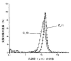
図3は、実施例6および7(表III)の多孔質のセラミック物品の細孔分布を図で比較している。図4は、実施例3および4(表III)の多孔質のセラミック物品の細孔分布を図で比較している。高速ピーク/高速冷却/熟成の焼成サイクルで得られた細孔分布(実施例4,7)は、標準的な焼成サイクル(実施例3,6)で得られるものよりもはるかに狭い分布を有する。上記実施例におけるバッチでは、細孔形成剤としてジャガイモデンプンを使用した。ジャガイモデンプンを、カンナ、サーゴ、サヤマメ、およびトウモロコシデンプンなどの単一のデンプンモデルで置き換えると、本発明の焼成スケジュールに従って焼成する多孔質のセラミック物品の細孔分布は、さらに狭くなることが予想される。 FIG. 3 graphically compares the pore distribution of the porous ceramic articles of Examples 6 and 7 (Table III). FIG. 4 graphically compares the pore distribution of the porous ceramic articles of Examples 3 and 4 (Table III). The pore distribution obtained in the fast peak / fast cooling / ripening firing cycle (Examples 4, 7) has a much narrower distribution than that obtained in the standard firing cycle (Examples 3, 6). . In the batches in the above examples, potato starch was used as a pore former. Replacing potato starch with a single starch model such as canna, sago, peas, and corn starch is expected to further narrow the pore distribution of porous ceramic articles fired according to the firing schedule of the present invention. The
図5は、本明細書に開示する焼成スケジュールの実施の形態を図示するものであり、高速昇温段階(FR)、温度における高速昇温速度(RU)を有する領域、温度の高速下降速度(RD)を有する領域、ピーク温度(T1)を含むピーク部分(P)、熟成温度の下限値(T2A)、および熟成温度の上限値(T2B)を例証している。図5の実施の形態に例証するように、高速昇温段階における開始時の初期温度は1300℃である。 FIG. 5 illustrates an embodiment of a firing schedule disclosed herein, which includes a fast ramp-up phase (FR), a region having a fast ramp-up rate (RU) in temperature, a fast ramp-down rate of temperature ( The region having RD), the peak portion (P) including the peak temperature (T1) , the lower limit value of the aging temperature (T2A), and the upper limit value of the aging temperature (T2B ) are illustrated. As illustrated in the embodiment of FIG. 5, the initial temperature at the start of the fast temperature ramp-up stage is 1300 ° C.
図6は、本明細書に開示する実施の形態を例証する焼成スケジュールの別の実施の形態を示しており、ここで、未焼成体が曝露される焼成環境の温度を、150時間の時点で開始される高速昇温段階の前、および170時間の時点で終了する保持段階の後の両方について変え、その後、焼成環境の温度を室温まで下降させるが、ここで冷却速度は、亀裂を生じさせないように十分に遅く、例えば焼成された部分の大きさによって決まる。例えば、室温と約1200℃(ここでは0〜150時間)の間、約20℃/時間から約70℃/時間の平均速度を有する平均焼成速度が用いられ、細孔形成剤の焼却段階は、(例えば細孔形成剤の焼却温度の範囲内に保持するか、または微速(10時間から50時間の時点で200から300℃に上昇)で行った後、中間昇温速度(50時間から150時間の時点で300℃から1200℃に上昇)を提供することができる。焼成サイクルはさらに、高速昇温段階およびそれに続く保持段階を含み、ここで高速昇温段階は、比較的高温(1200℃より高い)からピーク温度までを含み、該ピーク温度は、好ましくは1430〜1440℃であり、いずれの場合にも、保持段階における平均温度よりも少なくとも5℃高く、保持段階は、平均温度が1415〜1435℃、好ましくは1420℃より高く、 さらには1425℃より高く、好ましくは1420℃〜1435℃に保たれ、それによって保持の間にコージエライト相が形成される。高速昇温速度は50℃/時間以上、75℃/時間以上、100℃/時間以上、または120℃/時間以上でありうる。1200℃よりも高い高速昇温速度を比較的高い保持温度(1420℃より高い)と組み合わせて使用することにより、多孔質のセラミック物品の独特な微細構造特性が達成されうる。コージエライト相の初期形成の間に細孔が成分の粘性流で満たされるように、コージエライト形成成分の粘性流が促進されることにより、4.0μm未満の小さい細孔の相対量は実質的に低減されると考えられる。 FIG. 6 shows another embodiment of a firing schedule illustrating the embodiment disclosed herein, where the temperature of the firing environment to which the green body is exposed is measured at 150 hours. Change both before the fast ramp-up phase that is initiated and after the hold phase that ends at 170 hours, after which the temperature of the firing environment is lowered to room temperature, where the cooling rate does not cause cracking Slow enough, for example depending on the size of the fired part. For example, between room temperature and about 1200 ° C. (0 to 150 hours in this case), the average firing rate is used from about 20 ° C. / time with an average rate of about 70 ° C. / time, incineration stage of the pore forming agent, (For example, hold within the range of the incineration temperature of the pore- forming agent, or after performing at a slow speed (increase from 200 to 300 ° C. from 10 to 50 hours), then intermediate heating rate (from 50 to 150 hours) At a temperature of 300 ° C. to 1200 ° C.) The firing cycle further includes a fast heating stage followed by a holding stage, where the fast heating stage is at a relatively high temperature (from 1200 ° C.). High) to peak temperature, which is preferably 1430-1440 ° C., in each case at least 5 ° C. higher than the average temperature in the holding phase, The temperature is 1415 to 1435 ° C., preferably higher than 1420 ° C., more preferably higher than 1425 ° C., preferably 1420 ° C. to 1435 ° C., thereby forming a cordierite phase during the holding. It may be 50 ° C./hour or more, 75 ° C./hour or more, 100 ° C./hour or more, or 120 ° C./hour or more, and a high temperature rising rate higher than 1200 ° C. with a relatively high holding temperature (higher than 1420 ° C.). When used in combination, the unique microstructural characteristics of the porous ceramic article can be achieved: the viscous flow of the cordierite-forming component so that the pores are filled with the viscous flow of the component during the initial formation of the cordierite phase. It is considered that the relative amount of small pores of less than 4.0 μm is substantially reduced by the promotion of.
本発明を特定の実施の形態に関して説明してきたが、本開示の利益を享受する当業者は、本明細書に開示する本発明の範囲から逸脱することなく、他の実施の形態を発案できることを認識するであろう。したがって、本発明の範囲は、添付の特許請求の範囲によってのみ、限定されるべきである。 Although the present invention has been described in terms of particular embodiments, those skilled in the art who have the benefit of this disclosure can devise other embodiments without departing from the scope of the invention disclosed herein. You will recognize. Accordingly, the scope of the invention should be limited only by the attached claims.
Claims (5)
コージエライトセラミック形成成分からなる未焼成体を提供する工程と、
前記未焼成体を、0.5℃/分より大きい平均昇温速度で1000℃より高い初期温度から1400℃より高いピーク温度まで昇温する昇温段階と、前記ピーク温度からセラミック相が形成される温度範囲にある熟成温度まで下降させる段階と、前記熟成温度の上限値と前記熟成温度の下限値の間に4〜20時間保持する保持段階を含む焼成環境に曝露することにより加熱する工程と、
を有してなり、
前記熟成温度の上限値が前記ピーク温度よりも少なくとも5℃低いことを特徴とする方法。 A method for producing an article of porous cordierite ceramic material comprising:
Providing a green body comprising a cordierite ceramic forming component;
A temperature rising stage in which the green body is heated from an initial temperature higher than 1000 ° C. to a peak temperature higher than 1400 ° C. at an average temperature rising rate greater than 0.5 ° C./min, and a ceramic phase is formed from the peak temperature. A step of lowering to an aging temperature within a certain temperature range, and heating by exposure to a firing environment comprising a holding step of holding between the upper limit value of the aging temperature and the lower limit value of the aging temperature for 4 to 20 hours ; ,
Having
How the upper limit value of the pre-Symbol aging temperature, wherein at least 5 ° C. lower than the peak temperature.
Applications Claiming Priority (3)
| Application Number | Priority Date | Filing Date | Title |
|---|---|---|---|
| US96721907P | 2007-08-31 | 2007-08-31 | |
| US60/967,219 | 2007-08-31 | ||
| PCT/US2008/010229 WO2009029276A1 (en) | 2007-08-31 | 2008-08-28 | Method of firing green bodies into porous ceramic articles |
Publications (3)
| Publication Number | Publication Date |
|---|---|
| JP2010537930A JP2010537930A (en) | 2010-12-09 |
| JP2010537930A5 JP2010537930A5 (en) | 2013-03-28 |
| JP5276107B2 true JP5276107B2 (en) | 2013-08-28 |
Family
ID=39865417
Family Applications (1)
| Application Number | Title | Priority Date | Filing Date |
|---|---|---|---|
| JP2010522960A Expired - Fee Related JP5276107B2 (en) | 2007-08-31 | 2008-08-28 | Method of firing from green body to porous ceramic article |
Country Status (7)
| Country | Link |
|---|---|
| US (1) | US8187525B2 (en) |
| EP (1) | EP2183199B1 (en) |
| JP (1) | JP5276107B2 (en) |
| CN (1) | CN101808957B (en) |
| AT (1) | ATE500209T1 (en) |
| DE (1) | DE602008005321D1 (en) |
| WO (1) | WO2009029276A1 (en) |
Families Citing this family (19)
| Publication number | Priority date | Publication date | Assignee | Title |
|---|---|---|---|---|
| PL2188228T3 (en) * | 2007-08-31 | 2019-05-31 | Corning Inc | Cordierite honeycomb article and method of manufacture |
| WO2009048156A1 (en) * | 2007-10-12 | 2009-04-16 | Hitachi Metals, Ltd. | Cordierite ceramic honeycomb filter and process for producing the same |
| WO2009073082A1 (en) * | 2007-11-29 | 2009-06-11 | Corning Incorporated | System and method for forming ceramic precursor material for thin-walled ceramic honeycomb structures |
| US9856177B2 (en) | 2010-05-28 | 2018-01-02 | Corning Incorporated | Cordierite porous ceramic honeycomb articles |
| US9334191B2 (en) | 2010-05-28 | 2016-05-10 | Corning Incorporated | Methods for forming ceramic honeycomb articles |
| EP2646392B1 (en) * | 2010-11-29 | 2017-07-12 | Corning Incorporated | Process for control of cordierite filter properties |
| US8609032B2 (en) | 2010-11-29 | 2013-12-17 | Corning Incorporated | Porous ceramic honeycomb articles and methods for making the same |
| US9005517B2 (en) * | 2012-05-16 | 2015-04-14 | Corning Incorporated | Single-fire two-step soak method |
| US9315425B2 (en) | 2013-10-28 | 2016-04-19 | Universiti Brunei Darussalam | Macroporous ceramic body, method of manufacture and uses thereof |
| CN104692773B (en) * | 2013-12-05 | 2016-08-17 | 遵义泥牛黄工艺品有限公司 | A kind of manufacture method of fully natural green ceramic |
| CN109219589B (en) | 2016-05-31 | 2022-04-26 | 康宁股份有限公司 | Porous article and method of making same |
| US20200231506A1 (en) | 2017-07-24 | 2020-07-23 | Corning Incorporated | Antioxidants in green ceramic bodies containing various oils for improved firing |
| EP3694824A1 (en) | 2017-10-31 | 2020-08-19 | Corning Incorporated | Batch compositions comprising pre-reacted inorganic particles and methods of manufacture of green bodies therefrom |
| US11932582B2 (en) * | 2018-06-29 | 2024-03-19 | Corning Incorporated | Honeycomb bodies with controlled porosity gradient and firing methods thereof |
| EP3844123A1 (en) | 2018-08-31 | 2021-07-07 | Corning Incorporated | Cordierite-indialite-pseudobrookite structured ceramic bodies, batch composition mixtures, and methods of manufacturing ceramic bodies therefrom |
| US11976012B2 (en) | 2018-11-16 | 2024-05-07 | Corning Incorporated | Cordierite-containing ceramic bodies, batch composition mixtures, and methods of manufacturing cordierite-containing ceramic bodies |
| WO2024097046A1 (en) | 2022-10-31 | 2024-05-10 | Corning Incorporated | Higher temperature extrusion of ceramic precursor paste |
| WO2024097048A1 (en) | 2022-10-31 | 2024-05-10 | Corning Incorporated | Method of inducing a reduced wall drag state in a high wall drag ceramic precursor paste |
| CN117209247A (en) * | 2023-08-04 | 2023-12-12 | 常州市柚米家居用品有限公司 | Lithium-free heat-resistant ceramic and preparation method thereof |
Family Cites Families (30)
| Publication number | Priority date | Publication date | Assignee | Title |
|---|---|---|---|---|
| JPS6041022B2 (en) * | 1978-01-24 | 1985-09-13 | 日本碍子株式会社 | Manufacturing method for cordierite ceramics |
| US4528275A (en) * | 1984-06-04 | 1985-07-09 | General Electric Company | Mullite-cordierite composite ceramic and method for preparation |
| JPS63310773A (en) * | 1987-06-10 | 1988-12-19 | Shinagawa Refract Co Ltd | Method for drying metal fiber reinforced refractory |
| JPH0625024B2 (en) * | 1988-11-16 | 1994-04-06 | 住友金属鉱山株式会社 | Method for manufacturing dielectric porcelain |
| DE3905895C1 (en) * | 1989-02-25 | 1990-05-23 | Schott Glaswerke, 6500 Mainz, De | |
| JPH0738930B2 (en) * | 1990-03-30 | 1995-05-01 | 日本碍子株式会社 | Manufacturing method of porous ceramic filter |
| JP2981034B2 (en) * | 1991-09-30 | 1999-11-22 | 日本碍子株式会社 | Method for firing ceramic honeycomb structure |
| JP3130979B2 (en) * | 1991-09-30 | 2001-01-31 | 京セラ株式会社 | Manufacturing method of cordierite ceramics |
| JP3156171B2 (en) * | 1994-10-05 | 2001-04-16 | 日立造船株式会社 | Method for sintering ZrO2 compact |
| JPH092878A (en) * | 1995-02-08 | 1997-01-07 | Sumitomo Electric Ind Ltd | Silicon nitride sintered compact and its production |
| CN1210835A (en) * | 1997-07-28 | 1999-03-17 | 康宁股份有限公司 | Method of producing cordierite bodies utilizing substantially reduced firing times |
| US6087281A (en) * | 1998-02-25 | 2000-07-11 | Corning Incorporated | Low CTE cordierite bodies with narrow pore size distribution and method of making same |
| KR20010078396A (en) * | 1998-11-20 | 2001-08-20 | 알프레드 엘. 미첼슨 | Fabrication of low thermal expansion, high strength cordierite structures |
| US6723274B1 (en) * | 1999-12-09 | 2004-04-20 | Saint-Gobain Ceramics & Plastics, Inc. | High-purity low-resistivity electrostatic chucks |
| JP5468717B2 (en) * | 2000-06-01 | 2014-04-09 | コーニング インコーポレイテッド | Cordierite body |
| JP2002160976A (en) * | 2000-11-21 | 2002-06-04 | Hitachi Metals Ltd | Method for manufacturing ceramic honeycomb structure |
| JP4094830B2 (en) * | 2000-11-24 | 2008-06-04 | 日本碍子株式会社 | Porous honeycomb filter and manufacturing method thereof |
| JP4266103B2 (en) * | 2001-12-07 | 2009-05-20 | 日本碍子株式会社 | Method for producing porous ceramic body |
| US6736875B2 (en) * | 2001-12-13 | 2004-05-18 | Corning Incorporated | Composite cordierite filters |
| JP2003277162A (en) | 2002-01-21 | 2003-10-02 | Ngk Insulators Ltd | Porous honeycomb structural body, application thereof and manufacturing method therefor |
| WO2004002608A1 (en) * | 2002-06-26 | 2004-01-08 | Corning Incorporated | Magnesium aluminum silicate structures for dpf applications |
| US6864198B2 (en) * | 2003-01-30 | 2005-03-08 | Corning Incorporated | Cordierite ceramic body and method |
| US7179316B2 (en) * | 2003-06-25 | 2007-02-20 | Corning Incorporated | Cordierite filters with reduced pressure drop |
| US7976768B2 (en) * | 2005-05-31 | 2011-07-12 | Corning Incorporated | Aluminum titanate ceramic forming batch mixtures and green bodies including pore former combinations and methods of manufacturing and firing same |
| US7485170B2 (en) * | 2005-11-30 | 2009-02-03 | Corning Incorporated | Narrow pore size distribution cordierite ceramic honeycomb articles and methods for manufacturing same |
| WO2007064454A2 (en) * | 2005-11-30 | 2007-06-07 | Corning Incorporated | Controlled pore size distribution porous ceramic honeycomb filter, honeycomb green body, batch mixture and manufacturing method therefor |
| JP4699885B2 (en) * | 2005-12-02 | 2011-06-15 | 日本碍子株式会社 | Manufacturing method of honeycomb structure |
| US7575618B2 (en) * | 2006-03-30 | 2009-08-18 | Corning Incorporated | Reactive binders for porous wall-flow filters |
| US7648548B2 (en) * | 2006-05-10 | 2010-01-19 | Corning Incorporated | High porosity cordierite composition |
| PL2188228T3 (en) * | 2007-08-31 | 2019-05-31 | Corning Inc | Cordierite honeycomb article and method of manufacture |
-
2008
- 2008-08-27 US US12/229,828 patent/US8187525B2/en not_active Expired - Fee Related
- 2008-08-28 EP EP08795681A patent/EP2183199B1/en not_active Not-in-force
- 2008-08-28 JP JP2010522960A patent/JP5276107B2/en not_active Expired - Fee Related
- 2008-08-28 DE DE602008005321T patent/DE602008005321D1/en active Active
- 2008-08-28 WO PCT/US2008/010229 patent/WO2009029276A1/en active Application Filing
- 2008-08-28 AT AT08795681T patent/ATE500209T1/en not_active IP Right Cessation
- 2008-08-28 CN CN200880110230.6A patent/CN101808957B/en not_active Expired - Fee Related
Also Published As
| Publication number | Publication date |
|---|---|
| JP2010537930A (en) | 2010-12-09 |
| US8187525B2 (en) | 2012-05-29 |
| EP2183199B1 (en) | 2011-03-02 |
| CN101808957B (en) | 2013-06-05 |
| EP2183199A1 (en) | 2010-05-12 |
| US20090062105A1 (en) | 2009-03-05 |
| DE602008005321D1 (en) | 2011-04-14 |
| WO2009029276A1 (en) | 2009-03-05 |
| ATE500209T1 (en) | 2011-03-15 |
| CN101808957A (en) | 2010-08-18 |
Similar Documents
| Publication | Publication Date | Title |
|---|---|---|
| JP5276107B2 (en) | Method of firing from green body to porous ceramic article | |
| JP2010537930A5 (en) | ||
| US7486962B2 (en) | Extruded porous substrate having inorganic bonds | |
| JP5224291B2 (en) | Baking method of green body containing pore forming agent and aluminum titanate ceramic forming batch material | |
| JP4266103B2 (en) | Method for producing porous ceramic body | |
| JP2007510615A (en) | Ceramic body based on aluminum titanate | |
| EP1277714A1 (en) | Honeycomb structure and method for its manufacture | |
| EP1951637A2 (en) | System for extruding a porous substrate | |
| US7544320B2 (en) | Method of manufacturing porous ceramic body | |
| WO2008044508A1 (en) | Process for producing cordierite ceramic honeycomb filter | |
| JP2017006828A (en) | Method for producing honeycomb structure | |
| JP5075606B2 (en) | Silicon carbide based porous material | |
| JP2016534001A (en) | Cross-linked starch for pore formation in ceramics | |
| AU2007284302B2 (en) | An extruded porous substrate having inorganic bonds | |
| JP3130979B2 (en) | Manufacturing method of cordierite ceramics | |
| WO2014028048A1 (en) | Method of preparing high porosity ceramic material | |
| JP2008043922A (en) | Manufacturing method of base material for exhaust gas cleaning filter | |
| JPH07223871A (en) | Degreasing method for production of ceramic porous material |
Legal Events
| Date | Code | Title | Description |
|---|---|---|---|
| A621 | Written request for application examination |
Free format text: JAPANESE INTERMEDIATE CODE: A621 Effective date: 20110817 |
|
| A521 | Request for written amendment filed |
Free format text: JAPANESE INTERMEDIATE CODE: A523 Effective date: 20120419 |
|
| A977 | Report on retrieval |
Free format text: JAPANESE INTERMEDIATE CODE: A971007 Effective date: 20121119 |
|
| A131 | Notification of reasons for refusal |
Free format text: JAPANESE INTERMEDIATE CODE: A131 Effective date: 20121127 |
|
| A524 | Written submission of copy of amendment under article 19 pct |
Free format text: JAPANESE INTERMEDIATE CODE: A524 Effective date: 20130204 |
|
| TRDD | Decision of grant or rejection written | ||
| A01 | Written decision to grant a patent or to grant a registration (utility model) |
Free format text: JAPANESE INTERMEDIATE CODE: A01 Effective date: 20130423 |
|
| A61 | First payment of annual fees (during grant procedure) |
Free format text: JAPANESE INTERMEDIATE CODE: A61 Effective date: 20130516 |
|
| R150 | Certificate of patent or registration of utility model |
Free format text: JAPANESE INTERMEDIATE CODE: R150 Ref document number: 5276107 Country of ref document: JP Free format text: JAPANESE INTERMEDIATE CODE: R150 |
|
| R250 | Receipt of annual fees |
Free format text: JAPANESE INTERMEDIATE CODE: R250 |
|
| R250 | Receipt of annual fees |
Free format text: JAPANESE INTERMEDIATE CODE: R250 |
|
| R250 | Receipt of annual fees |
Free format text: JAPANESE INTERMEDIATE CODE: R250 |
|
| R250 | Receipt of annual fees |
Free format text: JAPANESE INTERMEDIATE CODE: R250 |
|
| LAPS | Cancellation because of no payment of annual fees |