JP5274545B2 - Door lock - Google Patents
Door lock Download PDFInfo
- Publication number
- JP5274545B2 JP5274545B2 JP2010504769A JP2010504769A JP5274545B2 JP 5274545 B2 JP5274545 B2 JP 5274545B2 JP 2010504769 A JP2010504769 A JP 2010504769A JP 2010504769 A JP2010504769 A JP 2010504769A JP 5274545 B2 JP5274545 B2 JP 5274545B2
- Authority
- JP
- Japan
- Prior art keywords
- bolt
- counter
- protrusion
- door lock
- shaft
- Prior art date
- Legal status (The legal status is an assumption and is not a legal conclusion. Google has not performed a legal analysis and makes no representation as to the accuracy of the status listed.)
- Expired - Fee Related
Links
Images


Classifications
-
- E—FIXED CONSTRUCTIONS
- E05—LOCKS; KEYS; WINDOW OR DOOR FITTINGS; SAFES
- E05C—BOLTS OR FASTENING DEVICES FOR WINGS, SPECIALLY FOR DOORS OR WINDOWS
- E05C5/00—Fastening devices with bolts moving otherwise than only rectilinearly and only pivotally or rotatively
-
- E—FIXED CONSTRUCTIONS
- E05—LOCKS; KEYS; WINDOW OR DOOR FITTINGS; SAFES
- E05B—LOCKS; ACCESSORIES THEREFOR; HANDCUFFS
- E05B15/00—Other details of locks; Parts for engagement by bolts of fastening devices
- E05B15/10—Bolts of locks or night latches
-
- E—FIXED CONSTRUCTIONS
- E05—LOCKS; KEYS; WINDOW OR DOOR FITTINGS; SAFES
- E05B—LOCKS; ACCESSORIES THEREFOR; HANDCUFFS
- E05B15/00—Other details of locks; Parts for engagement by bolts of fastening devices
- E05B15/10—Bolts of locks or night latches
- E05B15/102—Bolts having movable elements
-
- E—FIXED CONSTRUCTIONS
- E05—LOCKS; KEYS; WINDOW OR DOOR FITTINGS; SAFES
- E05B—LOCKS; ACCESSORIES THEREFOR; HANDCUFFS
- E05B15/00—Other details of locks; Parts for engagement by bolts of fastening devices
- E05B15/10—Bolts of locks or night latches
- E05B15/102—Bolts having movable elements
- E05B2015/105—Two pivoting latch elements with opposite inclined surfaces mounted on one slidable main latch-piece
-
- Y—GENERAL TAGGING OF NEW TECHNOLOGICAL DEVELOPMENTS; GENERAL TAGGING OF CROSS-SECTIONAL TECHNOLOGIES SPANNING OVER SEVERAL SECTIONS OF THE IPC; TECHNICAL SUBJECTS COVERED BY FORMER USPC CROSS-REFERENCE ART COLLECTIONS [XRACs] AND DIGESTS
- Y10—TECHNICAL SUBJECTS COVERED BY FORMER USPC
- Y10T—TECHNICAL SUBJECTS COVERED BY FORMER US CLASSIFICATION
- Y10T292/00—Closure fasteners
- Y10T292/08—Bolts
- Y10T292/0801—Multiple
- Y10T292/082—Spring arm
- Y10T292/0821—Combined motion
-
- Y—GENERAL TAGGING OF NEW TECHNOLOGICAL DEVELOPMENTS; GENERAL TAGGING OF CROSS-SECTIONAL TECHNOLOGIES SPANNING OVER SEVERAL SECTIONS OF THE IPC; TECHNICAL SUBJECTS COVERED BY FORMER USPC CROSS-REFERENCE ART COLLECTIONS [XRACs] AND DIGESTS
- Y10—TECHNICAL SUBJECTS COVERED BY FORMER USPC
- Y10T—TECHNICAL SUBJECTS COVERED BY FORMER US CLASSIFICATION
- Y10T292/00—Closure fasteners
- Y10T292/08—Bolts
- Y10T292/096—Sliding
- Y10T292/0969—Spring projected
-
- Y—GENERAL TAGGING OF NEW TECHNOLOGICAL DEVELOPMENTS; GENERAL TAGGING OF CROSS-SECTIONAL TECHNOLOGIES SPANNING OVER SEVERAL SECTIONS OF THE IPC; TECHNICAL SUBJECTS COVERED BY FORMER USPC CROSS-REFERENCE ART COLLECTIONS [XRACs] AND DIGESTS
- Y10—TECHNICAL SUBJECTS COVERED BY FORMER USPC
- Y10T—TECHNICAL SUBJECTS COVERED BY FORMER US CLASSIFICATION
- Y10T292/00—Closure fasteners
- Y10T292/08—Bolts
- Y10T292/096—Sliding
- Y10T292/1014—Operating means
Description
本発明は、ドアロックに関し、ドアロックの前方プレートの長手方向において軸に嵌合された本体部分を備えると共に軸の周囲において前記本体部分上に枢動可能に支持されている2つのボルト部品を備えているデュアルアクション(二重作用)ボルトを備えたドアロックに関する。 The present invention relates to a door lock, comprising two main body parts that are fitted on a shaft in the longitudinal direction of the front plate of the door lock and that are pivotally supported on the main body portion around the shaft. The present invention relates to a door lock equipped with a dual action bolt.
ドアロックは、多くの用途において、ドアロックのデッドボルト手段が抵抗がない状態にあるときにいずれかの方向に押すことによって開くことが出来なければならない。デッドボルト手段は、ドアロック内に設けられ且つボルトをデッドボルト位置にロックするために使用することができる手段を指している。デッドボルト位置においては、ボルトは、ロック本体から外方へ突出している状態にある。 In many applications, the door lock must be able to be opened by pushing in either direction when the deadlock means of the door lock is in an unresisting state. Deadbolt means refers to means provided in the door lock and that can be used to lock the bolt in the deadbolt position. At the dead bolt position, the bolt projects outward from the lock body.
当該用途及びその他の用途において、ドアロックは、2つのボルト部品を備えたデュアルアクションボルトからなる。これらのボルト部品は、いわゆる傾斜ボルトであり、ドアが閉められているときにストライカプレートと接触して当該傾斜ボルトをドアロック本体内へと進入させる傾斜面を備えている。当該ボルト部品は、ドアが回転される方向に関係なく、ドアが回転されて閉じられるときに、当該ボルト部品がストライカプレートと接する傾斜面を常に形成するように、デュアルアクション本体に枢動可能に嵌合されている。 In this and other applications, the door lock consists of a dual action bolt with two bolt parts. These bolt parts are so-called inclined bolts, and have an inclined surface that contacts the striker plate when the door is closed and allows the inclined bolt to enter the door lock body. The bolt component can be pivoted to the dual action body so that the bolt component always forms an inclined surface that contacts the striker plate when the door is rotated and closed, regardless of the direction in which the door is rotated. It is mated.
図1は、2つのボルト部品2と、本体3と、当該本体に結合された状態に配置されている軸4とを備えた従来技術によるデュアルアクションボルト1を示している。当該ボルト部品は、軸上に枢動可能に連結されている。この図は、両方のボルト部品が同じ方向に回されている状態にある側方から見たボルトを示している。別の言い方をすると、ストライカプレートは、ドアの閉鎖状態において一方のボルト部品を他方のボルト部品と同じ位置へと押している。この場合には、各ボルト部品の側面5は相互に合致した傾斜面を形成している。当該ボルト部品は、ボルトの回転を制限するために、リミッタ面6A,6Bを備えている。当該ボルト部品の端位置においては、ボルト部品のリミッタ面のどちらかが本体支持面7に当接して、ボルト部品が軸に対して枢動するのを阻止している。図1に示されている状態においては、ボルト部品は、当該ボルト部品が観察者から更に離れる方向へ回転することができない端位置にある。ボルト部品は、図1においては、ボルト部品の第二のリミッタ面6Bが本体支持面7と接するまで、観察者に近づく方へ回すことができる。
FIG. 1 shows a
両方のボルト部品はまた、軸4の長手方向のうちボルト本体部分3から離れる方向に向けられた突出部8をも備えている。これらの突出部は、ドアロックの前方プレートの内面と協働するように配置されているカウンタ面9を備えている。デュアルアクションボルトがロック本体から突出位置へと突出しているときに、どちらかのボルト部品内の突出部のカウンタ面9は、前方プレート(図1における上方ボルト部品のカウンタ面)の内側面と接している。従って、前方プレートの内側面は、一方のボルト部品を、他方のボルト部品が配置されている位置と反対側の端位置へと回転させるようにガイドする。言い換えると、デュアルアクションボルトの両方のボルト部品は、ボルトが突出位置にあるときに正反対の端位置にある。
Both bolt parts also comprise a protrusion 8 that is oriented away from the bolt body part 3 in the longitudinal direction of the shaft 4. These protrusions comprise a
デュアルアクションボルトを備えているドアロックにおける問題点は、作動中に、ボルト部品2が垂直方向において相対的に離れる方向に回転する傾向があるという点である。ボルト部品の回転によって、軸ジャーナル及び軸穴の両方において、軸4の不均一な摩耗が生じる。このことにより、ボルト部品間の隙間11が拡がり、ボルト部品の端縁10が前方プレート内のボルト穴の端縁に対して摩擦される。ボルト穴の端縁に対して端縁が摩擦されることによって、当該ドアロックの作動が妨げられ且つボルトが最早ロック本体内へ或いはロック本体から適正に動かないので誤動作さえ生じるかも知れない。更に、ドアを開/閉する際に、最初に主としてボルト部品のうちの一方に力がかかり、これによって、ロック本体内でボルト本体が回転する傾向がある。この回転は、完全な動作を確保するためには、当該ロックの他の構造において考慮しなければならない。
A problem with door locks with dual action bolts is that during operation, the bolt component 2 tends to rotate in a direction that is relatively far apart in the vertical direction. The rotation of the bolt parts causes uneven wear of the shaft 4 in both the shaft journal and the shaft hole. This widens the
本発明は、デュアルアクションボルトのボルト部品が相対的に離れる方向へ回転することを減じることを目的とする。 It is an object of the present invention to reduce the rotation of the bolt parts of the dual action bolt in a direction away from each other.
当該目的は、特許請求の範囲に記載されたようにして達成される。特許請求の範囲には、本発明の種々の実施形態が記載されている。 The object is achieved as described in the claims. In the claims, various embodiments of the invention are described.
本発明の概念は、ボルト部品が前方プレートの内側面と協働するような配置とされている別の突出部をも備えている場合に、ボルト部品の不所望な回転を減じるか又は完全に阻止することができるようにすることである。ボルト部品を軸上に支持することに関して、第二の突出部が、前記離れる方向に面している突出部とは対照的に軸線方向両側に配置されている。当該第二の突出部は、前記前方プレートの内側面と協働するように配置されている第二のカウンタ面を備えている。 The concept of the present invention reduces or eliminates undesired rotation of the bolt component when the bolt component also includes another protrusion that is arranged to cooperate with the inner surface of the front plate. Is to be able to stop. With respect to supporting the bolt part on the shaft, the second protrusions are arranged on both sides in the axial direction as opposed to the protrusions facing away from said direction. The second protrusion includes a second counter surface arranged to cooperate with the inner surface of the front plate.
以下、添付図面を参考にして本発明を更に詳細に説明する。 Hereinafter, the present invention will be described in more detail with reference to the accompanying drawings.
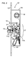
図2は、本発明によるドアロック12の実施例を示している。当該ドアロックは、前方プレート13に嵌め込まれたロック本体14を備えており、当該ロック本体はデュアルアクションボルト15を備えており、当該デュアルアクションボルトは、引っ込み位置と前方プレート13内のボルト穴16(図3)を介して前記ロック本体から突出している突出ロック位置との間を、往復直線動作によって動かすことができる。当該ボルトは、(ドアロックにおいて一般的であるように)前記突出位置に向けてばね荷重がかけられている。
FIG. 2 shows an embodiment of a
当該ドアロックは更に、デッドボルト手段17を備えており、当該デッドボルト手段は、当該デッドボルト手段が前記デュアルアクションボルトが前記突出位置からロック本体14内の引っ込み位置へと動かされるのを阻止するデッドボルト位置へと動かすことができる。図2の実施例におけるデッドボルト手段は、デッドボルト位置にロックされている。この実施例においては、デッドボルト手段内のローラー17Aは、ロックレバー17B及びロック部材17Cが前記デッドボルト位置から動くのを阻止している。
The door lock further includes a dead bolt means 17 that prevents the dead bolt means from moving the dual action bolt from the protruding position to a retracted position in the
当該ドアロックはまた、通常は、デッドボルト手段を制御するための制御手段をも備えている。当該ドアロックは、電気的に制御されているソレノイド20、補助ボルト19及び/又は制御スピンドル手段18を備えていても良い。前記補助ボルトは、ドアが開かれているときにボルトがデッドボルト位置へと動くのを阻止するが、ドアが閉められているときには当該動きを許容する。制御スピンドル手段18は、例えば、シリンダ本体、ハンドル及び/又はノブを備えている。制御スピンドル手段及び補助ボルトからデッドボルト手段内のローラー17Aへの結合は、単に点線によって示されている。ソレノイド20は、ソレノイドスピンドルを介してローラー17Aに連結されている。
The door lock typically also includes control means for controlling the deadbolt means. The door lock may comprise an electrically controlled
図4及び5A〜5Dは、本発明によるドアロックのデュアルアクションボルトを示している。図6A〜6Cは、種々の方向から見たデュアルアクションボルトのボルト部品を示している。デュアルアクションボルト15は、前方プレート13に対してほぼ長手方向の軸29に嵌合された本体部分22を備えている。デュアルアクションボルトはまた、軸29の周囲において本体部分22上に枢動可能に支持されている2つのボルト部品23をも備えている。図4においては、ボルト部品及び本体部分は相対的に分離されている。図5A〜5Dにおいては、ボルト部品は本体部分22上に枢動可能に支持されている。ボルト部品は、軸29のための穴32(図6B)を備えている。ボルト部品は、前記軸が当該ボルト部品の穴内に位置するように軸の周囲に嵌合されている。当該穴内にある軸の部分27,28は、ボルト部品のための支持部、言い換えると、前記ボルト部品の軸を支持するための場所を形成している。図5Bにおいて、デュアルアクションボルトは軸29の方向から示されており、2つのボルト部品は同じ方向に回転された状態であり、この場合には、ボルト部品は合致した傾斜面を形成している。図5Cにおいては、デュアルアクションボルトは、ボルト部品が異なる方向に回転された状態で軸の方向から示されており、この場合にはボルト部品の傾斜面は交差している。
4 and 5A-5D show a door lock dual action bolt according to the present invention. 6A-6C show the bolt parts of a dual action bolt viewed from various directions. The
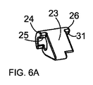
ボルト部品は、軸29の長手方向において、本体部分22から離れる方向を向いている突出部24を備えており、当該突出部は、前記前方プレートの内側面30と協働する構造とされているカウンタ面25を備えている。両方のボルト部品はまた第二の突出部26をも備えており、当該第二の突出部26は、前記軸のボルト部品支持部27に対して、前記離れる方向を向いている突出部24と対照的に軸29の方向における反対側に配置されている。当該第二の突出部は、前記前方プレートの内面30と協働する配置とされている第二のカウンタ面31を備えている。
The bolt component includes a protruding
当該デュアルアクションボルトは前記突出位置に向けてばね荷重がかけられているので、カウンタ面25,31は、当該カウンタ面が前方プレートの内側面と接しているときに、ボルト部品を交差位置(図5A及び5C)へと回転させる。前記突出部はまた、デュアルアクションボルトのドアロック本体からの突出を制限する(図2参照)。ボルト部品は、当該ボルト部品のカウンタ面25,31が軸支持位置27,28に対して軸線方向の両側にあるときに、相対的に離れるように回転する傾向はない。第二のカウンタ面31は、ボルト部品が前記前方プレートに対向しているときに、第一のボルト部品が第二のボルト部品から離れる方向に回転するのを阻止する。当該ボルト部品は、上記したように2つのカウンタ面を備えているので、前記前方プレートに対するボルト部品の回転もまた最少化されるか又は阻止される。回転が阻止されるので、軸29上に不均一な摩耗が生じないであろう。このことにより、軸の比較的薄い寸法が可能になる。
Since the dual action bolt is spring-loaded toward the protruding position, the counter surfaces 25 and 31 cross the bolt parts when the counter surface is in contact with the inner surface of the front plate (see FIG. Rotate to 5A and 5C). The protrusion also limits the protrusion of the dual action bolt from the door lock body (see FIG. 2). The bolt parts do not tend to rotate away from each other when the counter surfaces 25, 31 of the bolt parts are on both sides in the axial direction with respect to the shaft support positions 27, 28. The
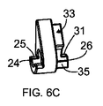
図6A〜6Cは、ボルト部品の一実施例を示している。図5A〜5Dにおいては、デュアルアクションボルトは組み立てられた状態にある。第一のボルト部品の第二の突出部26は、ボルト部品23の第二突出部26同士が本体22及び軸29の両側に位置するように、軸29の方向において第二のボルト部品に対向している。図3は、前方から見たドアロックを示しており、前方プレート13内のボルト穴16が示されている。ボルト穴16の端縁は前方プレート内にカウンタ突出部21を備えており、第二のカウンタ面31は前記カウンタ突出部21と協働するように配置されている。ボルトが突出位置へと直線的に動くことができるようにさせるために、前方プレートのカウンタ突出部のための切取り部33が、両方のボルト部品内に設けられている。図面から分かるように、ボルト部品の第二の突出部26の第二のカウンタ面31は、本体部分22の中間部分に配置されている。これらの図面はまた、当該デュアルアクションボルトの両方のボルト部品が同一であることをも示している。
6A-6C show one embodiment of a bolt component. 5A-5D, the dual action bolt is in an assembled state. The second projecting
ボルト部品23の外方を向いた突出部24と第二の突出部26とのコーナーのうちの少なくとも一つは丸味が付けられている。これらのコーナーの丸味付けは、作動中の摩耗及び裂傷を少なくすることを意図している。図4は、本体部分22及びその軸29が堅牢な一体部品例えば鋳造部品であることを示している。しかしながら、ボルト本体内に本体の軸を別個に嵌合できる穴を設けることもまた可能である。
At least one of the corners of the projecting
図面は、両方のボルト部品が本体の軸29のための穴32を備えていることを示している(図6B)。提供された図面に示された実施例においては、ボルト部品の軸に対する回転を制限するために、第一のリミッタ面34が穴と関連して設けられている。当該第一のリミッタ面は穴の端縁に対して接線方向に延びている面である。ボルト部品の第二の突出部26の第二のカウンタ面31と反対側に設けられた面35は、当該ボルト部品が他方の方向に回転するのを制限するための第二のリミッタ面を形成している。デュアルアクションボルトの本体部分22は、軸29の面に対する接線方向の当該本体の端部に設けられた第一のカウンタリミッタ面35Aと、当該本体部分の両側に設けられた第二のカウンタリミッタ面36とを備えている。第一のカウンタリミッタ面35Aは、前記第一のリミッタ面34と協働するように配置されており、第二のカウンタリミッタ面36は第二のリミッタ面35と協働するように配置されている。当該リミッタ面の目的は、ボルト部品が軸に対して抵抗なく回転するのを阻止することである。図5B及び5Cは端部位置にあるボルト部品を示している。ボルト部品が更に回転することを許容されている場合には、前方プレートのボルト穴及びストライカプレートのボルト穴内でのボルトの往復直線動作が妨げられるか又は阻止さえされる。当該リミッタ面は、ボルト部品内の穴のすぐ隣に配置される場合には、精密に作ることができる。このことにより、製造公差によるボルト部品の過剰な回転が減じられる。
The drawing shows that both bolt parts are provided with
図7は、カウンタ面39を備えた第二の突出部38が軸の長手方向に対して横切る方向に軸から離れる方向に(好ましくは軸の径方向に)延びている突出部であるボルト部品の第二の実施例37を示している。この実施例のボルト部品を使用しているデュアルアクションボルトを備えたドアロックにおいては、第二の突出部38は、ボルト穴16の側方端縁上にある第一のプレートの内側面と協働する配置とされる。この場合には、ボルト部品は、必ずしも、他方のボルト部品と対向する軸の方向に切取り部33又は突出部を備える必要はない。
FIG. 7 shows a bolt component which is a protrusion in which a
本発明によるドアロックはまた、図面に示されているもの以外のタイプのデュアルアクションボルトを具備することもできることは明らかである。例えば、ロック手段17に対向する本体部分22の側部は、種々の形状とすることができる。従って、本発明の概念の範囲内に含まれるあらゆる実施例を具備することができる。
Obviously, the door lock according to the invention can also be equipped with a dual action bolt of a type other than that shown in the drawings. For example, the side portion of the
1 デュアルアクションボルト
2 ボルト部品
3 本体
4 軸
5 側面
6A,6B リミッタ面
7 本体支持面
8 突出部
9 カウンタ面
10 端縁
11 隙間
12 ドアロック
13 前方プレート
14 ロック本体
15 デュアルアクションボルト
16 ボルト穴
17 デッドボルト手段
17A ローラー
17B ロックレバー
17C ロック部材
18 制御スピンドル手段
19 補助ボルト
20 ソレノイド
23 ボルト部品
24 突出部
25 カウンタ面
26 第二の突出部
27,28 軸の部分
27 ボルト部品の支持部
29 軸
30 前方プレートの内面
31 第二のカウンタ面
31 第二のかみ合い面
32 穴
33 切取り部
34 第一のリミッタ面
35 第二の突出部の面
35A 第一のカウンタリミッタ面
36 第二のカウンタリミッタ面
38 第二の突出部
39 カウンタ面
DESCRIPTION OF
Claims (8)
前記ボルト部品(23)は第二の突出部(26)を備えており、当該第二の突出部は、前記軸の前記ボルト部品の支持部に関して、前記離れる方向に面している突出部と対照的に前記軸(29)の方向における反対側に配置されており、当該第二の突出部は、前記前方プレートの内側面(30)と協働するように配置された第二のカウンタ面(31)を備えていることを特徴とするドアロック。 A door lock including a lock body (14) fitted into the front plate (13), the lock body protruding from the lock body via a retracted position and a bolt hole (16) of the front plate (13). A dual action bolt (15) that can be moved between the positions by a reciprocating linear motion, the dual action bolt (15) being spring loaded toward the protruding position, and the dual action bolt The bolt (15) includes a body portion (22) mated with a longitudinal axis (29) relative to the front plate and is pivotally supported on the body portion around the axis. Two bolt parts, the bolt parts being away from the body part in the longitudinal direction of the shaft (29) And a counter surface (25) arranged to cooperate with an inner surface (30) of the front plate, the door lock Further includes a deadbolt means (17) capable of being moved to a deadbolt position that prevents the dual action bolt from being moved from the protruding position to the retracted position in the lock body (14). Is a lock,
The bolt part (23) comprises a second protrusion (26), the second protrusion being a protrusion facing in the direction away from the support part of the bolt part of the shaft. In contrast, a second counter surface arranged on the opposite side in the direction of the axis (29), the second protrusion being arranged to cooperate with the inner surface (30) of the front plate (31) The door lock characterized by the above-mentioned.
前記本体部分(22)が、前記軸の面に対する接線方向において当該本体部分の端部に第一のカウンタリミッタ面(35A)を備え且つ当該本体部分の側部に第二のカウンタリミッタ面(36)を備えており、前記第一のカウンタリミッタ面(35A)は前記第一のリミッタ面(34)と協働するように配置されており、前記第二のカウンタリミッタ面(36)は前記第二のリミッタ面(35)と協働する配置とされていることを特徴とする請求項5に記載のドアロック。 Both of the bolt parts (23) are provided with holes (32) for the shaft (29) of the body, in order to limit the rotation of the bolt parts (23) relative to the shaft. One limiter surface (34) is provided in association with the hole, and the first limiter surface (34) is a surface that is tangential to the edge of the hole, and the second limiter surface (34). The second limiter for limiting the rotation of the bolt component in the other direction by the surface (35) of the second protrusion (26) of the bolt component provided on the opposite side of the counter surface (31) of the bolt Forming a surface,
The main body portion (22) includes a first counter limiter surface (35A) at an end portion of the main body portion in a tangential direction with respect to the surface of the shaft, and a second counter limiter surface (36 ), The first counter limiter surface (35A) is arranged to cooperate with the first limiter surface (34), and the second counter limiter surface (36) is the first counter limiter surface (36). 6. Door lock according to claim 5, characterized in that it is arranged to cooperate with the second limiter surface (35).
Applications Claiming Priority (3)
| Application Number | Priority Date | Filing Date | Title |
|---|---|---|---|
| FI20075296 | 2007-04-27 | ||
| FI20075296A FI120416B (en) | 2007-04-27 | 2007-04-27 | Lock of the door |
| PCT/FI2008/050173 WO2008132273A1 (en) | 2007-04-27 | 2008-04-09 | Door lock |
Publications (2)
| Publication Number | Publication Date |
|---|---|
| JP2010525199A JP2010525199A (en) | 2010-07-22 |
| JP5274545B2 true JP5274545B2 (en) | 2013-08-28 |
Family
ID=38009949
Family Applications (1)
| Application Number | Title | Priority Date | Filing Date |
|---|---|---|---|
| JP2010504769A Expired - Fee Related JP5274545B2 (en) | 2007-04-27 | 2008-04-09 | Door lock |
Country Status (27)
| Country | Link |
|---|---|
| US (1) | US8474884B2 (en) |
| EP (1) | EP2140083B1 (en) |
| JP (1) | JP5274545B2 (en) |
| KR (1) | KR101351774B1 (en) |
| CN (1) | CN101688406B (en) |
| AR (1) | AR066319A1 (en) |
| AU (1) | AU2008244161B2 (en) |
| BR (1) | BRPI0809742B1 (en) |
| CA (1) | CA2680568C (en) |
| CL (1) | CL2008001204A1 (en) |
| DK (1) | DK2140083T3 (en) |
| EG (1) | EG25178A (en) |
| ES (1) | ES2391687T3 (en) |
| FI (1) | FI120416B (en) |
| HK (1) | HK1141850A1 (en) |
| HR (1) | HRP20120808T1 (en) |
| IL (1) | IL201775A (en) |
| MA (1) | MA31376B1 (en) |
| MX (1) | MX2009011395A (en) |
| MY (1) | MY150158A (en) |
| PL (1) | PL2140083T3 (en) |
| RU (1) | RU2416011C1 (en) |
| SI (1) | SI2140083T1 (en) |
| TW (1) | TWI440764B (en) |
| UA (1) | UA93793C2 (en) |
| WO (1) | WO2008132273A1 (en) |
| ZA (1) | ZA200906289B (en) |
Families Citing this family (8)
| Publication number | Priority date | Publication date | Assignee | Title |
|---|---|---|---|---|
| ES2400557B1 (en) * | 2011-04-15 | 2013-08-01 | Talleres De Escoriaza, S.A. | Convertible lock |
| FI124791B (en) | 2012-12-19 | 2015-01-30 | Abloy Oy | Lock of the door |
| FI124790B (en) | 2012-12-19 | 2015-01-30 | Abloy Oy | Locks |
| RU2555617C2 (en) * | 2013-12-03 | 2015-07-10 | Доор Энд Виндоу Хардвэ Ко. | Door lock |
| US11220839B2 (en) * | 2017-05-15 | 2022-01-11 | Spectrum Brands, Inc. | Dead locking latch assembly |
| EP3438382B1 (en) * | 2017-08-01 | 2020-02-26 | dormakaba Deutschland GmbH | Latch assembly of a lock |
| US20220010594A1 (en) * | 2020-07-01 | 2022-01-13 | Cmech (Guangzhou) Ltd. | Latch bolt installation structure and door lock using such structure |
| SE545278C2 (en) * | 2021-06-14 | 2023-06-13 | Se Dev Ab | Double-action latch bolt assembly with first and second protrusible members and door lock arrangement comprising the double-action latch bolt assembly |
Family Cites Families (25)
| Publication number | Priority date | Publication date | Assignee | Title |
|---|---|---|---|---|
| US2209551A (en) * | 1938-03-07 | 1940-07-30 | Anderson Bolling Mfg Co | Door latch |
| US3361464A (en) * | 1966-04-04 | 1968-01-02 | Von Duprin Inc | Reversible latch assembly with turnable latch head |
| JPS58132077U (en) * | 1982-03-02 | 1983-09-06 | 昭和ロツク株式会社 | latch lock |
| KR920000069B1 (en) * | 1984-12-10 | 1992-01-06 | 고구산 킨조꾸 코오교오 가부시기가이샤 | Electronic door lock assembly |
| US4682802A (en) * | 1985-10-10 | 1987-07-28 | Schlage Lock Company | Lock mechanism and a spring and cam assembly therefor |
| FI82287C (en) * | 1987-04-13 | 1991-02-11 | Waertsilae Oy Ab | DOERRLAOS. |
| SU1448020A1 (en) | 1987-06-10 | 1988-12-30 | Предприятие П/Я А-3903 | Lock |
| JPH07100986B2 (en) | 1990-04-10 | 1995-11-01 | 株式会社長柄製作所 | Latch guide device for lock, latch retracting device, and latch release device |
| US5113676A (en) * | 1990-12-31 | 1992-05-19 | Misak Panossian | Double acting dead latch mechanism |
| US5249831A (en) * | 1991-12-02 | 1993-10-05 | American Security Products Co. | Security lock for safes and the like having inertial operated counterweight |
| US5311168A (en) * | 1992-09-10 | 1994-05-10 | Pease Industries, Inc. | Lock set with self-contained door alarm and annunciator system |
| GB9411595D0 (en) * | 1994-06-09 | 1994-08-03 | Pickersgill Kaye Ltd | Door securing device for secondary locking system |
| FR2726026B1 (en) * | 1994-10-20 | 1996-11-29 | Deny | ELECTROMECHANICAL LOCK FOR DOUBLE ACTION EMERGENCY EXIT |
| GB2296737B (en) * | 1995-01-04 | 1998-02-11 | Fan Lai Ho Tzu | Door lock assembly |
| RU2176715C2 (en) | 1996-09-18 | 2001-12-10 | Богоявленский Георгий Серафимович | Locking device |
| KR980008391U (en) * | 1998-02-26 | 1998-04-30 | 고영배 | Door locks with anti-theft protection |
| US6349982B2 (en) * | 1999-07-02 | 2002-02-26 | Corbin Russwin, Inc. | Reversible mortise lock |
| US6393878B1 (en) * | 2000-05-22 | 2002-05-28 | Corbin Russwin, Inc. | Mortise lock |
| US6578888B1 (en) * | 2000-06-21 | 2003-06-17 | Tesa Entry Systems Inc. | Mortise lock with automatic deadbolt |
| RU2181423C1 (en) | 2000-08-04 | 2002-04-20 | Открытое акционерное общество специального машиностроения и металлургии "Мотовилихинские заводы" | Locking device |
| FR2829520B1 (en) * | 2001-09-11 | 2004-11-12 | Jpm Sa | UNIVERSAL MOUNT LOCK |
| US6619705B2 (en) * | 2002-01-04 | 2003-09-16 | Schlage Lock Company | Mortise lockset with internal clutch |
| US6926315B2 (en) * | 2003-01-29 | 2005-08-09 | Hardware Specialties, Inc. | Push pull latch bolt mechanism |
| US7007985B2 (en) * | 2003-08-26 | 2006-03-07 | Onity, Inc. | Automatic deadbolt mechanism for a mortise lock |
| JP2005350898A (en) * | 2004-06-09 | 2005-12-22 | Miwa Lock Co Ltd | Lock for fittings |
-
2007
- 2007-04-27 FI FI20075296A patent/FI120416B/en active IP Right Grant
-
2008
- 2008-04-09 KR KR1020097022357A patent/KR101351774B1/en active IP Right Grant
- 2008-04-09 PL PL08736822T patent/PL2140083T3/en unknown
- 2008-04-09 CA CA 2680568 patent/CA2680568C/en active Active
- 2008-04-09 EP EP20080736822 patent/EP2140083B1/en active Active
- 2008-04-09 DK DK08736822.1T patent/DK2140083T3/en active
- 2008-04-09 BR BRPI0809742-9A patent/BRPI0809742B1/en active IP Right Grant
- 2008-04-09 WO PCT/FI2008/050173 patent/WO2008132273A1/en active Application Filing
- 2008-04-09 AU AU2008244161A patent/AU2008244161B2/en active Active
- 2008-04-09 MX MX2009011395A patent/MX2009011395A/en active IP Right Grant
- 2008-04-09 JP JP2010504769A patent/JP5274545B2/en not_active Expired - Fee Related
- 2008-04-09 MY MYPI20094288A patent/MY150158A/en unknown
- 2008-04-09 SI SI200830784T patent/SI2140083T1/en unknown
- 2008-04-09 ES ES08736822T patent/ES2391687T3/en active Active
- 2008-04-09 RU RU2009143894A patent/RU2416011C1/en active
- 2008-04-09 US US12/597,630 patent/US8474884B2/en active Active
- 2008-04-09 CN CN200880013459.8A patent/CN101688406B/en active Active
- 2008-04-10 TW TW97112943A patent/TWI440764B/en not_active IP Right Cessation
- 2008-04-25 CL CL2008001204A patent/CL2008001204A1/en unknown
- 2008-04-25 AR ARP080101779 patent/AR066319A1/en not_active Application Discontinuation
- 2008-09-04 UA UAA200912185A patent/UA93793C2/en unknown
-
2009
- 2009-09-10 ZA ZA200906289A patent/ZA200906289B/en unknown
- 2009-10-25 EG EG2009101581A patent/EG25178A/en active
- 2009-10-27 IL IL201775A patent/IL201775A/en active IP Right Grant
- 2009-11-16 MA MA32346A patent/MA31376B1/en unknown
-
2010
- 2010-08-25 HK HK10108130A patent/HK1141850A1/en unknown
-
2012
- 2012-10-09 HR HRP20120808AT patent/HRP20120808T1/en unknown
Also Published As
Similar Documents
| Publication | Publication Date | Title |
|---|---|---|
| JP5274545B2 (en) | Door lock | |
| US8261586B2 (en) | Lock assembly including a rotary blocking device and tamper resistant mechanism | |
| TWI453331B (en) | Door lock | |
| JP2010519436A (en) | Latch assembly | |
| FI119155B (en) | Key and cylinder lock with locking discs | |
| JP5496878B2 (en) | Locking device | |
| TW201723293A (en) | Lock body | |
| TWI434985B (en) | Door lock | |
| CN108798307A (en) | Vehicle door latch device | |
| JP4810684B2 (en) | Movable lever biasing device | |
| JP5006963B2 (en) | Actuator for vehicle door latch device | |
| US11087933B2 (en) | Safety switch | |
| JP2011252291A (en) | Clutch device and actuator | |
| JPH09219125A (en) | Key switch device |
Legal Events
| Date | Code | Title | Description |
|---|---|---|---|
| A621 | Written request for application examination |
Free format text: JAPANESE INTERMEDIATE CODE: A621 Effective date: 20101105 |
|
| A977 | Report on retrieval |
Free format text: JAPANESE INTERMEDIATE CODE: A971007 Effective date: 20120725 |
|
| A131 | Notification of reasons for refusal |
Free format text: JAPANESE INTERMEDIATE CODE: A131 Effective date: 20120731 |
|
| A521 | Request for written amendment filed |
Free format text: JAPANESE INTERMEDIATE CODE: A523 Effective date: 20121023 |
|
| TRDD | Decision of grant or rejection written | ||
| A01 | Written decision to grant a patent or to grant a registration (utility model) |
Free format text: JAPANESE INTERMEDIATE CODE: A01 Effective date: 20130426 |
|
| A61 | First payment of annual fees (during grant procedure) |
Free format text: JAPANESE INTERMEDIATE CODE: A61 Effective date: 20130514 |
|
| R150 | Certificate of patent or registration of utility model |
Free format text: JAPANESE INTERMEDIATE CODE: R150 Ref document number: 5274545 Country of ref document: JP Free format text: JAPANESE INTERMEDIATE CODE: R150 |
|
| R250 | Receipt of annual fees |
Free format text: JAPANESE INTERMEDIATE CODE: R250 |
|
| R250 | Receipt of annual fees |
Free format text: JAPANESE INTERMEDIATE CODE: R250 |
|
| R250 | Receipt of annual fees |
Free format text: JAPANESE INTERMEDIATE CODE: R250 |
|
| R250 | Receipt of annual fees |
Free format text: JAPANESE INTERMEDIATE CODE: R250 |
|
| LAPS | Cancellation because of no payment of annual fees |