JP5267095B2 - Running condition evaluation device - Google Patents
Running condition evaluation device Download PDFInfo
- Publication number
- JP5267095B2 JP5267095B2 JP2008316259A JP2008316259A JP5267095B2 JP 5267095 B2 JP5267095 B2 JP 5267095B2 JP 2008316259 A JP2008316259 A JP 2008316259A JP 2008316259 A JP2008316259 A JP 2008316259A JP 5267095 B2 JP5267095 B2 JP 5267095B2
- Authority
- JP
- Japan
- Prior art keywords
- driving force
- threshold
- driver
- vehicle
- vehicle speed
- Prior art date
- Legal status (The legal status is an assumption and is not a legal conclusion. Google has not performed a legal analysis and makes no representation as to the accuracy of the status listed.)
- Expired - Fee Related
Links
Images


Classifications
-
- B—PERFORMING OPERATIONS; TRANSPORTING
- B60—VEHICLES IN GENERAL
- B60W—CONJOINT CONTROL OF VEHICLE SUB-UNITS OF DIFFERENT TYPE OR DIFFERENT FUNCTION; CONTROL SYSTEMS SPECIALLY ADAPTED FOR HYBRID VEHICLES; ROAD VEHICLE DRIVE CONTROL SYSTEMS FOR PURPOSES NOT RELATED TO THE CONTROL OF A PARTICULAR SUB-UNIT
- B60W50/00—Details of control systems for road vehicle drive control not related to the control of a particular sub-unit, e.g. process diagnostic or vehicle driver interfaces
- B60W50/08—Interaction between the driver and the control system
- B60W50/14—Means for informing the driver, warning the driver or prompting a driver intervention
-
- B—PERFORMING OPERATIONS; TRANSPORTING
- B60—VEHICLES IN GENERAL
- B60R—VEHICLES, VEHICLE FITTINGS, OR VEHICLE PARTS, NOT OTHERWISE PROVIDED FOR
- B60R16/00—Electric or fluid circuits specially adapted for vehicles and not otherwise provided for; Arrangement of elements of electric or fluid circuits specially adapted for vehicles and not otherwise provided for
- B60R16/02—Electric or fluid circuits specially adapted for vehicles and not otherwise provided for; Arrangement of elements of electric or fluid circuits specially adapted for vehicles and not otherwise provided for electric constitutive elements
- B60R16/023—Electric or fluid circuits specially adapted for vehicles and not otherwise provided for; Arrangement of elements of electric or fluid circuits specially adapted for vehicles and not otherwise provided for electric constitutive elements for transmission of signals between vehicle parts or subsystems
Landscapes
- Engineering & Computer Science (AREA)
- Automation & Control Theory (AREA)
- Mechanical Engineering (AREA)
- Human Computer Interaction (AREA)
- Transportation (AREA)
- Combined Controls Of Internal Combustion Engines (AREA)
- Control Of Driving Devices And Active Controlling Of Vehicle (AREA)
- Electric Propulsion And Braking For Vehicles (AREA)
- Control Of Vehicle Engines Or Engines For Specific Uses (AREA)
Description
本発明は、車両の走行状態を評価する走行状態装置に関し、特に、走行状態の評価を運転者に伝えて燃費悪化の抑制を図る走行状態評価装置に関する。 The present invention relates to a traveling state apparatus that evaluates a traveling state of a vehicle, and more particularly, to a traveling state evaluation apparatus that transmits evaluation of a traveling state to a driver and suppresses deterioration of fuel consumption.
一般に、公道を走行する車両の加速は、低速走行中で大きく高速走行中で小さいものとなるが、通常の走行を実現する上で必要な加速は一定の範囲内に収まるものである。そして、この一定の範囲内から逸脱する加速が燃費の悪化を引き起こすことを運転者に分かり易く伝えることは、エネルギーの有効利用や地球環境の保護を図る上で望ましいことである。 In general, the acceleration of a vehicle traveling on a public road is large during low-speed traveling and small during high-speed traveling, but the acceleration necessary for realizing normal traveling is within a certain range. And it is desirable for the purpose of effective use of energy and protection of the global environment to inform the driver in an easy-to-understand manner that acceleration deviating from the certain range causes deterioration of fuel consumption.
このような状況の下、燃費効率が良好な操作領域を外れないようにアクセル開度を誘導するアクセル開度表示装置が知られている(例えば、特許文献1参照。)。 Under such circumstances, there is known an accelerator opening degree display device that guides the accelerator opening degree so as not to deviate from an operation region where fuel efficiency is good (see, for example, Patent Document 1).
このアクセル開度表示装置は、車種毎に異なるパワートレイン系(クラッチ、トランスミッション、プロペラシャフト、デファレンシャルギア、ドライブシャフト)の伝達効率を考慮しながら車速に応じて設定される目標アクセル開度と実際のアクセル開度との間の差(乖離量)を表示して燃費効率が良好となるアクセル開度となるよう運転者を誘導する。 This accelerator opening indicator displays the target accelerator opening and the actual accelerator opening that are set according to the vehicle speed while taking into account the transmission efficiency of the powertrain system (clutch, transmission, propeller shaft, differential gear, drive shaft) that differs for each vehicle type. The difference between the accelerator opening (the amount of deviation) is displayed, and the driver is guided to the accelerator opening that provides good fuel efficiency.
また、急加速又は急減速が行われた時点における乗員、積載貨物、及び積載燃料の重量を含めた車両総重量に基づいて加速度閾値又は減速度閾値を算出し、車速センサが検出した車速に基づいて算出される加速度又は減速度がこれらの閾値以上となった場合に、加速(減速)限度を超えたことを運転者に報知する加速度評価装置も知られている(例えば、特許文献2参照。)。
しかしながら、特許文献1に記載のアクセル開度表示装置は、燃費悪化の有無を判定する指標としてアクセル開度を用いるので毎回の演算が単純ではあるものの、燃費に影響を与える車両特性(車種毎に異なるパワートレイン系の伝達効率、アクセル特性、若しくはシフト線、又は走行モード、シフト位置、若しくは車速等である。)を反映させることが十分にできないという問題がある。
However, the accelerator opening display device described in
一方で、特許文献2に記載の加速度評価装置のように、燃費悪化の有無を判定する指標として実際の加速度を用いた場合には、実際に急加速が行われてしまった後で加速限度を超えたことを運転者に報知することとなるので、燃費悪化をもたらす急加速を十分に抑制することができないという問題がある。
On the other hand, when the actual acceleration is used as an index for determining the presence or absence of fuel consumption deterioration as in the acceleration evaluation device described in
上述の点に鑑み、本発明は、より適切な指標を用いて車両状態を評価しながら燃費悪化の抑制を促すことができる走行状態評価装置を提供することを目的とする。 In view of the above-described points, an object of the present invention is to provide a traveling state evaluation device that can promote suppression of fuel consumption deterioration while evaluating a vehicle state using a more appropriate index.
上述の目的を達成するために、第一の発明に係る走行状態評価装置は、車速を検出する車速検出手段と、運転者が行った運転操作に応じて発生する車両を駆動するための駆動力を推定する駆動力推定手段と、前記車速検出手段により検出された車速に基づいて駆動力の閾値を設定する閾値設定手段と、前記駆動力推定手段により推定された駆動力と前記閾値設定手段により設定された閾値との間の関係を運転者に伝える駆動力情報伝達手段と、を備えることを特徴とする。 In order to achieve the above-described object, a traveling state evaluation device according to a first invention includes a vehicle speed detection unit that detects a vehicle speed, and a driving force for driving a vehicle that is generated in accordance with a driving operation performed by the driver. A driving force estimating means for estimating the driving force, a threshold setting means for setting a driving force threshold based on the vehicle speed detected by the vehicle speed detecting means, a driving force estimated by the driving force estimating means, and the threshold setting means. Driving force information transmitting means for transmitting a relationship between the set threshold and the driver to the driver.
また、第二の発明は、第一の発明に係る走行状態評価装置であって、前記駆動力推定手段は、未発生の駆動力を推定し、前記駆動力情報伝達手段は、該駆動力が実際に発生する前に、前記駆動力推定手段により推定された駆動力と前記閾値設定手段により設定された閾値との間の関係を運転者に伝えることを特徴とする。 The second aspect of the invention is a traveling state evaluation apparatus according to the first aspect of the invention, wherein the driving force estimating means estimates an ungenerated driving force, and the driving force information transmitting means Before actually occurring, the driver is informed of the relationship between the driving force estimated by the driving force estimating means and the threshold set by the threshold setting means.
また、第三の発明は、第一又は第二の発明に係る走行状態評価装置であって、前記駆動力推定手段により推定された駆動力が前記閾値設定手段により設定された閾値以上であるか否かを判定する駆動力適否判定手段を備え、前記駆動力情報伝達手段は、前記駆動力適否判定手段により駆動力が閾値以上であると判定された場合に、判定結果を運転者に伝えることを特徴とする。 Further, the third invention is the traveling state evaluation device according to the first or second invention, wherein the driving force estimated by the driving force estimating means is not less than a threshold set by the threshold setting means. Driving force suitability determining means for determining whether or not the driving force information transmitting means transmits the determination result to the driver when the driving force suitability determining means determines that the driving force is equal to or greater than a threshold value. It is characterized by.
また、第四の発明は、第一乃至第三の何れかの発明に係る走行状態評価装置であって、前記駆動力推定手段は、エンジン制御部がアクセル開度に基づいて算出したエンジントルクと、トランスミッション制御部がアクセル開度に基づいて算出したトランスミッションギア比及びトルコン比とに基づいて、駆動力を推定することを特徴とする。 The fourth aspect of the present invention is the traveling state evaluation apparatus according to any one of the first to third aspects, wherein the driving force estimation means includes an engine torque calculated by the engine control unit based on the accelerator opening. The transmission control unit estimates the driving force based on the transmission gear ratio and the torque converter ratio calculated based on the accelerator opening.
上述の手段により、本発明は、より適切な指標を用いて車両状態を評価しながら燃費悪化の抑制を促すことができる走行状態評価装置を提供することができる。 With the above-described means, the present invention can provide a traveling state evaluation device that can promote suppression of deterioration in fuel consumption while evaluating a vehicle state using a more appropriate index.
以下、図面を参照しつつ、本発明を実施するための最良の形態の説明を行う。 Hereinafter, the best mode for carrying out the present invention will be described with reference to the drawings.
図1は、本発明に係る走行状態評価装置の構成例を示すブロック図であり、走行状態評価装置100は、駆動力を指標として行った走行状態の評価を運転者に伝えて燃費悪化の抑制を図る車載装置であり、制御部1を有し、車速センサ2及びアクセル開度センサ3からの入力を受け、音声出力装置4及び表示装置5に制御信号を出力する。なお、これらの各構成要素は、CAN(Controller Area Network)やLIN(Local Interconnect Network)等の車載LANを介して接続されているものとする。
FIG. 1 is a block diagram illustrating a configuration example of a traveling state evaluation apparatus according to the present invention. The traveling
制御部1は、CPU(Central Processing Unit)、RAM(Random Access Memory)、ROM(Read Only Memory)等を備えたコンピュータであって、例えば、駆動力推定手段10、閾値設定手段11、駆動力適否判定手段12、及び駆動力情報伝達手段13のそれぞれに対応するプログラムをROMに記憶しながら、各手段に対応する処理をCPUに実行させる。
The
車速センサ2は、車両の速度を測定するセンサであり、例えば、各車輪に取り付けられ各車輪とともに回転する磁石による磁界の変化を磁気抵抗として読み取るMR(Magnetic Resistance)素子であって、その磁気抵抗を回転速度に比例したパルス信号として取り出すことで車輪の回転速度及び車両の速度を検出して制御部1に出力する。
The
アクセル開度センサ3は、アクセル開度を測定するためのセンサであり、例えば、アクセルペダルの踏み込み量を検出するポテンショメータであって、その検出値を制御部1に出力する。
The
音声出力装置4は、各種情報を音声出力するための装置であり、例えば、車載スピーカやブザーであって、制御部1が出力する制御信号に応じて警告音や音声案内を出力する。
The
表示装置5は、各種情報を表示するための装置であり、例えば、インジケータランプや車載ディスプレイ等であって、制御部1が出力する制御信号に応じてインジケータランプを点灯・消灯したり、グラフィックデータやテキストデータを表示したりする。
The
次に、制御部1が有する各種手段について説明する。
Next, various units included in the
駆動力推定手段10は、運転者が行った運転操作に応じて発生する、車両を駆動するための駆動力(走行パワー)を推定する手段であり、例えば、アクセル開度センサ3の出力に基づいて運転者によるアクセルの踏み込みに応じた駆動力を推定する。
The driving force estimation means 10 is a means for estimating the driving force (traveling power) for driving the vehicle, which is generated according to the driving operation performed by the driver, and is based on the output of the
車両を駆動するための駆動力は、例えば、トランスミッションギア後トルク×最終ギア比÷タイヤ半径で求められ、また、トランスミッションギア後トルクは、例えば、エンジントルク×トランスミッションギア比×トルコン比×動力伝達効率で求められる。 The driving force for driving the vehicle is obtained by, for example, transmission gear rear torque × final gear ratio ÷ tire radius, and transmission gear rear torque is, for example, engine torque × transmission gear ratio × torque ratio × power transmission efficiency. Is required.
なお、最終ギア比、タイヤ半径、及び動力伝達効率は、車種毎に予め設定される定数であり、エンジントルクは、アクセル開度及びエンジン回転数等に応じて変化する値であり、トランスミッションギア比及びトルコン比は、アクセル開度及びシフト位置等に応じて変化する値である。 The final gear ratio, tire radius, and power transmission efficiency are constants set in advance for each vehicle type, and the engine torque is a value that changes according to the accelerator opening, the engine speed, etc., and the transmission gear ratio. The torque converter ratio is a value that changes according to the accelerator opening, the shift position, and the like.
また、エンジントルク、トランスミッションギア比及びトルコン比は、通常、エンジンECU(図示せず。)がエンジン及びトランスミッションを制御する目的でアクセル開度センサ3の出力に応じて算出している値であり、駆動力推定手段10は、エンジンECUが実行するエンジントルク、トランスミッションギア比及びトルコン比を導き出すための演算と同じ演算を制御部1で実行し駆動力を推定する。
The engine torque, the transmission gear ratio, and the torque converter ratio are values that are usually calculated by an engine ECU (not shown) according to the output of the
なお、駆動力推定手段10は、エンジンECUが導き出したエンジントルク、トランスミッションギア比及びトルコン比の値をエンジンECUから受信した後でそれらの値を用いて駆動力を推定するための演算を実行するようにしてもよく、エンジンECUが導き出した駆動力をそのまま流用するようにしてもよい。 The driving force estimating means 10 receives the engine torque, transmission gear ratio, and torque converter ratio values derived by the engine ECU from the engine ECU, and then performs calculations for estimating the driving force using these values. Alternatively, the driving force derived by the engine ECU may be used as it is.
また、駆動力推定手段10は、運転者によってアクセルが踏み込まれた後、エンジン駆動力が実際に発生する前に(燃料が消費される前に)、瞬時に、その未発生のエンジン駆動力を推定する。後述の駆動力情報伝達手段13により運転者が加速を控える(アクセルの過剰な踏み込みをより迅速に中止する)ことによって消費を免れる燃料をできるだけ多くするためである。 Further, the driving force estimating means 10 instantaneously calculates the ungenerated engine driving force after the accelerator is depressed by the driver and before the engine driving force is actually generated (before the fuel is consumed). presume. This is because the driver refrains from acceleration by driving force information transmission means 13 (to be described later) (stops excessive depression of the accelerator more quickly) to increase the amount of fuel that can be avoided.
閾値設定手段11は、駆動力推定手段10が推定した駆動力が適切であるか否かを判定するための閾値を設定するための手段であり、例えば、駆動力推定手段10が駆動力を推定する度に車速センサ2の出力に基づいて設定される。
The threshold setting unit 11 is a unit for setting a threshold for determining whether or not the driving force estimated by the driving
この閾値は、適切であるとされる駆動力の許容最大値であり、例えば、各車速レベルにおいて適切であるとされる加速度の許容最大値に車両重量を乗じた値であって、車速と加速度又は駆動力の許容最大値との間の対応関係は、走行環境に基づいて予め決定されており(例えば、車両が販売される地域の交通事情に基づいて決定され、短い区間の走行が繰り返されるような地域ではその許容最大値が低めに設定される。その結果、他の地域に比べ比較的浅いアクセルペダルの踏み込みによって推定駆動力がその閾値を超過することとなる。)、ルックアップテーブルの形でROM等に記憶される。なお、車両重量は、車種毎に予め設定される値である。 This threshold is an allowable maximum value of driving force that is considered appropriate, for example, a value obtained by multiplying the allowable maximum value of acceleration that is appropriate at each vehicle speed level by the vehicle weight, and the vehicle speed and acceleration. Alternatively, the correspondence relationship between the allowable maximum value of the driving force is determined in advance based on the travel environment (for example, determined based on the traffic conditions in the area where the vehicle is sold, and traveling in a short section is repeated. In such areas, the maximum allowable value is set lower, and as a result, the estimated driving force exceeds the threshold when the accelerator pedal is depressed relatively shallowly compared to other areas). Is stored in a ROM or the like. The vehicle weight is a value set in advance for each vehicle type.
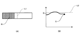
図2は、ルックアップテーブルの内容を図式化したグラフの一例であり、縦軸に駆動力、横軸に車速を配し、実線THが閾値の推移を示す。 FIG. 2 is an example of a graph that graphically illustrates the contents of the lookup table. The vertical axis indicates the driving force, the horizontal axis indicates the vehicle speed, and the solid line TH indicates the transition of the threshold value.
図2のグラフにおいて、閾値は、車速が0(km/h)からV1(km/h)まで上昇する間、値T1まで一定の増加率で増加し、その後、車速がV2(km/h)になるまでその値T1を維持し、その後、車速がV3(km/h)になるまで三段階の減少率で徐々に減少する。 In the graph of FIG. 2, the threshold value increases at a constant increase rate to the value T1 while the vehicle speed increases from 0 (km / h) to V1 (km / h), and then the vehicle speed increases to V2 (km / h). The value T1 is maintained until the vehicle speed becomes, and then gradually decreases at a three-step reduction rate until the vehicle speed reaches V3 (km / h).
このように、燃費悪化の有無を判定するための指標として駆動力(又は、その駆動力を車両重量で除することによって算出される加速度)を用いることによって、走行状態評価装置100は、閾値と車速と間の対応関係を示すルックアップテーブルを複数の車種で共用できるようになる。駆動力は、車両特性(車種毎に異なるパワートレイン系の伝達効率、アクセル特性、若しくはシフト線、又は走行モード、シフト位置、若しくは車速等である。)を既に反映させた値であるからである。
As described above, by using the driving force (or the acceleration calculated by dividing the driving force by the vehicle weight) as an index for determining the presence or absence of deterioration in fuel consumption, the running
駆動力適否判定手段12は、駆動力推定手段10が推定した駆動力が適切であるか否かを判定するための手段であり、駆動力推定手段10が推定した駆動力と閾値設定手段11が設定した閾値とを比較し、推定駆動力が閾値以上となる場合に、駆動力が過剰であると判定する。 The driving force suitability determination means 12 is a means for determining whether or not the driving force estimated by the driving force estimation means 10 is appropriate. The driving force estimated by the driving force estimation means 10 and the threshold setting means 11 It compares with the set threshold value, and when the estimated driving force is equal to or greater than the threshold value, it is determined that the driving force is excessive.
駆動力情報伝達手段13は、駆動力に関する情報を運転者に伝えるための手段であり、例えば、駆動力推定手段10が推定した駆動力と閾値設定手段11が設定した閾値との間の大小関係を音声出力装置4や表示装置5を用いて出力する。
The driving force
図3は、推定駆動力と閾値との間の大小関係を示す画像の例であり、図3(A)は、破線L1が閾値のレベルを示し、灰色領域Rが閾値に対する推定駆動力の相対的な大きさを示す。図3(A)は、現時点における推定駆動力が閾値未満であり、閾値の約80%のレベルであることを示す。 FIG. 3 is an example of an image showing the magnitude relationship between the estimated driving force and the threshold value. FIG. 3A shows the threshold level of the broken line L1, and the gray region R is the relative value of the estimated driving force to the threshold value. The typical size is shown. FIG. 3A shows that the estimated driving force at the present time is less than the threshold and is about 80% of the threshold.
また、図3(B)は、縦軸に駆動力、横軸に時間を配し、破線L2が閾値のレベルを示し、曲線Gが閾値に対する推定駆動力の相対的な大きさの推移を示し、マークCが現時点における閾値に対する推定駆動力の相対的な大きさを示す。図3(B)は、閾値未満にあった推定駆動力が閾値以上に増大し再び閾値未満に減少した状態を示す。 FIG. 3B shows the driving force on the vertical axis and time on the horizontal axis, the broken line L2 indicates the threshold level, and the curve G indicates the transition of the relative magnitude of the estimated driving force with respect to the threshold value. , Mark C indicates the relative magnitude of the estimated driving force with respect to the current threshold value. FIG. 3B shows a state in which the estimated driving force that was less than the threshold value has increased above the threshold value and has decreased again below the threshold value.
なお、駆動力情報伝達手段13は、駆動力を指標として情報を提示するが、加速度(駆動力を車両重量で除した値である。)を指標として情報を提示するようにしてもよい。
The driving force
また、駆動力情報伝達手段13は、推定駆動力が閾値以上となった場合に所定時間間隔で短い警告音を断続的に出力し、推定駆動力と閾値との間の差が大きくなるにつれてその間隔を短くしていくことで推定駆動力と閾値との間の大小関係を運転者に聴覚的に伝えるようにしてもよい。 The driving force information transmission means 13 intermittently outputs a short warning sound at a predetermined time interval when the estimated driving force exceeds the threshold, and as the difference between the estimated driving force and the threshold increases, By decreasing the interval, the magnitude relationship between the estimated driving force and the threshold value may be audibly transmitted to the driver.
また、駆動力情報伝達手段13は、駆動力適否判定手段12により、推定駆動力が閾値以上であり駆動力が過剰であると判定された場合に、インストルメントパネルに設置されたエコランプを点滅させ、或いは、そのエコランプを赤色で点灯させるようにしてもよい。なお、駆動力情報伝達手段13は、推定駆動力と閾値との間の差が大きくなるにつれてその点滅間隔を小さくし、運転者がエコランプを凝視しなくとも推定駆動力と閾値との間の大小関係を視覚的に認識できるようにしてもよい。
The driving force
また、駆動力情報伝達手段13は、推定駆動力が閾値未満の場合に、そのエコランプを消灯させ、或いは、そのエコランプを緑色で点灯させるようにしてもよい。なお、エコランプは、駆動力が過剰であることを示すエコランプと、駆動力が適切であることを示す別のエコランプとの複数構成であってもよい。
Further, when the estimated driving force is less than the threshold value, the driving force
次に、図4を参照しながら、走行状態評価装置100が駆動力情報を運転者に伝達し運転者による過度の加速を抑制する処理(以下、「加速抑制処理」とする。)について説明する。なお、図4は、加速抑制処理の流れを示すフローチャートであり、走行状態評価装置100は、所定周期で繰り返しこの加速抑制処理を実行するものとする。
Next, a process (hereinafter referred to as “acceleration suppression process”) in which the traveling
最初に、制御部1は、車速センサ2及びアクセル開度センサ3の出力を受けて、現時点における車速とアクセル開度とを検出する(ステップS1)。
First, the
その後、制御部1は、駆動力推定手段10により、検出した現時点におけるアクセル開度に基づいて、車両を前進させようとする駆動力を推定する(ステップS2)。
Thereafter, the
また、制御部1は、閾値設定手段11により、検出した現時点における車速とROMに記憶されたルックアップテーブルとに基づいて、駆動力推定手段10が推定する駆動力との比較に用いられる閾値を抽出して設定する(ステップS3)。
Further, the
なお、制御部1は、閾値設定手段11により閾値を設定した後で、駆動力推定手段10により駆動力を推定するようにしてもよく、二つの処理を同時並行で実行するようにしてもよい。
In addition, after setting the threshold value by the threshold value setting unit 11, the
その後、制御部1は、駆動力適否判定手段12により、駆動力推定手段10が推定した駆動力と閾値設定手段11が設定した閾値とを比較し、推定した駆動力が設定した閾値以上であるか否かを判定する(ステップS4)。
Thereafter, the
推定した駆動力が設定した閾値以上である場合(ステップS4のYES)、制御部1は、駆動力情報伝達手段13により、インストルメントパネルに設置されたエコランプを赤色で点滅或いは点灯させ、現に発生させようとする駆動力が閾値を超えており、燃費を悪化させることを運転者に伝えるようにする(ステップS5)。
If the estimated driving force is greater than or equal to the set threshold value (YES in step S4), the
一方、推定した駆動力が設定した閾値未満である場合(ステップS4のNO)、制御部1は、駆動力情報伝達手段13により、エコランプが点灯している場合にはそのエコランプを消灯させ、或いは、緑色で点灯させ、現に発生させようとする駆動力が閾値未満であり、燃費を悪化させるおそれがないことを運転者に伝えるようにする(ステップS6)。
On the other hand, when the estimated driving force is less than the set threshold value (NO in step S4), the
その後、制御部1は、駆動力情報伝達手段13により、駆動力適否判定手段12の判定結果に関係なく、推定した駆動力と設定した閾値との間の大小関係を音声出力装置4や表示装置5を用いて出力する(ステップS7)。
Thereafter, the
このようにして、運転者は、車載ディスプレイに表示された推定駆動力と閾値との間の大小関係を示す画像を見ながら自車両の走行状態を常に確認できることに加え、駆動力が閾値を超えようとする瞬間をエコランプで知ることができるので、燃費の悪化を効果的に抑制することができる。 In this way, the driver can always check the running state of the host vehicle while viewing the image showing the magnitude relationship between the estimated driving force and the threshold value displayed on the in-vehicle display, and the driving force exceeds the threshold value. Since the moment to try can be known by the eco lamp, the deterioration of fuel consumption can be effectively suppressed.
以上の構成により、走行状態評価装置100は、車種毎に異なる車両特性等を反映した駆動力を、燃費悪化の有無を判定する指標として採用するので、燃費悪化のおそれがあることをより正確に運転者に伝えることができる。
With the above configuration, the driving
また、走行状態評価装置100は、車種毎に異なる車両特性等を反映した駆動力を、燃費悪化の有無を判定する指標として採用するので、車種の違いを超えた共通のルックアップテーブル(閾値と車速との間の対応関係を表す表である。)を利用することができ、アクセル開度を指標として採用した場合のように、車種毎にルックアップテーブルを用意する必要が無い。
Moreover, since the driving
また、走行状態評価装置100は、加速度の実測値を指標として採用した場合のように急加速が既に行われた後で燃費が悪化したことを運転者に伝える態様と異なり、急加速が発生する直前に燃費悪化のおそれがあることを運転者に事前に伝えることができる。
Unlike the mode in which the traveling
次に、図5を参照しながら、本発明に係る走行状態評価装置の別の構成例について説明する。 Next, another configuration example of the traveling state evaluation apparatus according to the present invention will be described with reference to FIG.
走行状態評価装置200は、エンジン制御部30がアクセル開度に基づいて算出したエンジントルクの値と、トランスミッション制御部31がアクセル開度に基づいて算出したトランスミッションギア比及びトルコン比の値とに基づいて駆動力推定手段10が駆動力を推定する点で走行状態評価装置100と異なるが、その他の点で走行状態評価装置100と共通する。
The traveling
なお、走行状態評価装置100は、駆動力推定手段10により、アクセル開度に基づいてエンジントルク、トランスミッションギア比、及びトルコン比の値を制御部1に算出させながら駆動力を推定させている。
The traveling
エンジン制御部30及びトランスミッション制御部31は共に、エンジンECUに搭載される構成要素であって、ハードウェア、ソフトウェア、又は、両者を組み合わせたもののいずれであってもよい。
Both the
また、エンジン制御部30及びトランスミッション制御部31はそれぞれ、エンジンの制御、トランスミッションの制御という別の役割を有し、それぞれの役割を果たす上でエンジントルク、トランスミッションギア比、及びトルコン比の値を算出しており、駆動力推定のためだけにそれらの値を算出しているものではない。
Further, the
以上の構成により、走行状態評価装置200は、走行状態評価装置100が有する効果に加え、エンジンを制御するためにエンジン制御部30が算出したエンジントルクと、トランスミッションを制御するためにトランスミッション制御部31が算出したトランスミッションギア比及びトルコン比とをそのまま利用することにより、重複した演算処理を省略し、制御部1の演算負荷を低減させることができるという効果を有する。
With the above configuration, the traveling
以上、本発明の好ましい実施例について詳説したが、本発明は、上述した実施例に制限されることはなく、本発明の範囲を逸脱することなしに上述した実施例に種々の変形及び置換を加えることができる。 Although the preferred embodiments of the present invention have been described in detail above, the present invention is not limited to the above-described embodiments, and various modifications and substitutions can be made to the above-described embodiments without departing from the scope of the present invention. Can be added.
例えば、上述の実施例において、走行状態評価装置100、200は、エンジンECUから独立した装置として記載されるが、エンジンECUの一部として一体化されていてもよい。
For example, in the above-described embodiment, the traveling
また、走行状態評価装置100、200は、風向風速計、路面の状況を検出するための画像センサ、道路勾配を検出するための傾斜センサ等の各種センサの出力を用いて車両の走行抵抗(空気抵抗、ころがり抵抗、勾配抵抗等である。)を算出し、走行抵抗が大きい場合に、閾値設定手段11が設定した閾値を増大させ、反対に、走行抵抗が小さい場合に、閾値設定手段11が設定した閾値を減少させるように補正してもよい。
In addition, the traveling
閾値の増大補正は、運転者が周囲環境に応じた適切な範囲での加速を行っているにもかかわらず燃費悪化の発生を過度に警告してしまうことがないようにするためであり、閾値の減少補正は、周囲環境に応じた更なる燃費の向上を促すようにするためである。 The threshold value increase correction is to prevent the driver from excessively warning the occurrence of fuel consumption deterioration even though the driver is accelerating in an appropriate range according to the surrounding environment. This decrease correction is to promote further improvement in fuel consumption according to the surrounding environment.
1 制御部
2 車速センサ
3 アクセル開度センサ
4 音声出力装置
5 表示装置
10 駆動力推定手段
11 閾値設定手段
12 駆動力適否判定手段
13 駆動力情報伝達手段
30 エンジン制御部
31 トランスミッション制御部
100、200 走行状態評価装置
DESCRIPTION OF
Claims (3)
運転者が行った運転操作に応じて発生する車両を駆動するための駆動力を、運転者のアクセルペダルの踏み込みから検出されるアクセル開度に応じて変化する値と車種毎に予め設定される定数とを演算することによって、該駆動力が実際に発生する前に、未発生の駆動力として推定する駆動力推定手段と、
前記車速検出手段により検出された車速に基づいて車速と加速度又は駆動力との予め定められた対応関係から駆動力の閾値を設定する閾値設定手段と、
前記駆動力推定手段により推定された駆動力と前記閾値設定手段により設定された閾値との間の関係を運転者に伝える駆動力情報伝達手段と、を備え、
前記駆動力情報伝達手段は、駆動力が実際に発生する前に、前記駆動力推定手段により推定された駆動力と前記閾値設定手段により設定された閾値との間の関係を運転者に伝える、
ことを特徴とする走行状態評価装置。 Vehicle speed detection means for detecting the vehicle speed;
The driving force for driving the vehicle generated according to the driving operation performed by the driver is preset for each vehicle type and a value that changes according to the accelerator opening detected from the driver's depression of the accelerator pedal. A driving force estimating means for calculating a constant before calculating the driving force before the driving force is actually generated ;
Threshold setting means for setting a threshold of driving force from a predetermined correspondence between vehicle speed and acceleration or driving force based on the vehicle speed detected by the vehicle speed detecting means;
Driving force information transmitting means for transmitting a relationship between the driving force estimated by the driving force estimating means and the threshold set by the threshold setting means to the driver ;
Before SL driving force information transmission means before the driving force is actually generated, conveying the association between the set threshold value by the threshold value setting means and the estimated driving force by the driving force estimation means to the driver ,
A running state evaluation apparatus characterized by that.
前記駆動力情報伝達手段は、前記駆動力適否判定手段により駆動力が閾値以上であると判定された場合に、判定結果を運転者に伝える、
ことを特徴とする請求項1に記載の走行状態評価装置。 A driving force suitability determining means for determining whether or not the driving force estimated by the driving force estimating means is equal to or greater than a threshold set by the threshold setting means;
The driving force information transmitting means transmits a determination result to the driver when the driving force suitability determining means determines that the driving force is equal to or greater than a threshold value.
The traveling state evaluation apparatus according to claim 1.
ことを特徴とする請求項1又は2に記載の走行状態評価装置。 The driving force estimation means estimates the driving force based on the engine torque calculated based on the accelerator opening by the engine control unit and the transmission gear ratio and torque converter ratio calculated based on the accelerator opening by the transmission control unit. To
The traveling state evaluation apparatus according to claim 1 or 2, characterized by the above.
Priority Applications (6)
| Application Number | Priority Date | Filing Date | Title |
|---|---|---|---|
| JP2008316259A JP5267095B2 (en) | 2008-12-11 | 2008-12-11 | Running condition evaluation device |
| EP09799137A EP2356007B1 (en) | 2008-12-11 | 2009-11-25 | Driving condition evaluation device and evaluation method |
| KR1020117013294A KR101280711B1 (en) | 2008-12-11 | 2009-11-25 | Driving condition evaluation device and evaluation method |
| CN200980149838.4A CN102245456B (en) | 2008-12-11 | 2009-11-25 | Driving condition evaluation device and evaluation method |
| US13/133,960 US8525656B2 (en) | 2008-12-11 | 2009-11-25 | Driving condition evaluation device and evaluation method |
| PCT/IB2009/007552 WO2010067154A1 (en) | 2008-12-11 | 2009-11-25 | Driving condition evaluation device and evaluation method |
Applications Claiming Priority (1)
| Application Number | Priority Date | Filing Date | Title |
|---|---|---|---|
| JP2008316259A JP5267095B2 (en) | 2008-12-11 | 2008-12-11 | Running condition evaluation device |
Publications (3)
| Publication Number | Publication Date |
|---|---|
| JP2010137728A JP2010137728A (en) | 2010-06-24 |
| JP2010137728A5 JP2010137728A5 (en) | 2011-08-04 |
| JP5267095B2 true JP5267095B2 (en) | 2013-08-21 |
Family
ID=41682355
Family Applications (1)
| Application Number | Title | Priority Date | Filing Date |
|---|---|---|---|
| JP2008316259A Expired - Fee Related JP5267095B2 (en) | 2008-12-11 | 2008-12-11 | Running condition evaluation device |
Country Status (6)
| Country | Link |
|---|---|
| US (1) | US8525656B2 (en) |
| EP (1) | EP2356007B1 (en) |
| JP (1) | JP5267095B2 (en) |
| KR (1) | KR101280711B1 (en) |
| CN (1) | CN102245456B (en) |
| WO (1) | WO2010067154A1 (en) |
Families Citing this family (21)
| Publication number | Priority date | Publication date | Assignee | Title |
|---|---|---|---|---|
| DE102009010810B4 (en) * | 2009-02-27 | 2018-03-22 | Continental Automotive Gmbh | Device for displaying several detectable variables |
| DE102010042895A1 (en) * | 2010-10-25 | 2012-04-26 | Thilo Frey | Adjustment device for power control of an internal combustion engine and method for power control of the internal combustion engine |
| JP5141760B2 (en) * | 2010-12-28 | 2013-02-13 | 株式会社デンソー | Vehicle behavior data storage control system, electronic control device, data storage device |
| JP5206801B2 (en) * | 2011-01-19 | 2013-06-12 | 株式会社デンソー | Vehicle behavior data storage control system, electronic control device |
| US9361271B2 (en) * | 2011-09-27 | 2016-06-07 | Wipro Limited | Systems and methods to enable eco-driving |
| CN103057459B (en) * | 2011-10-19 | 2017-06-13 | 现代摩比斯株式会社 | Vehicular lamp and its control method |
| RU2565852C1 (en) * | 2011-12-28 | 2015-10-20 | Тойота Дзидося Кабусики Кайся | Device for deceleration factor calculation |
| CN104105630B (en) | 2012-02-03 | 2016-10-19 | 丰田自动车株式会社 | Deceleration parameter estimating device |
| DE102012203037A1 (en) * | 2012-02-28 | 2013-08-29 | Continental Automotive Gmbh | Method for determining the speed and / or position of a vehicle |
| CN104029682B (en) * | 2013-03-07 | 2015-11-18 | 广州汽车集团股份有限公司 | The acquisition methods of battery-driven car advisory speed and device |
| US9517771B2 (en) * | 2013-11-22 | 2016-12-13 | Ford Global Technologies, Llc | Autonomous vehicle modes |
| JP6374695B2 (en) * | 2014-04-28 | 2018-08-15 | 日立建機株式会社 | Road shoulder detection system and mine transport vehicle |
| CN105599772B (en) * | 2014-11-24 | 2018-06-22 | 上海通用汽车有限公司 | Vehicular intelligent driving assistance system and intelligent driving auxiliary control method |
| CN104574957B (en) * | 2014-12-23 | 2019-03-05 | 厦门雅迅网络股份有限公司 | A kind of method and system using wind speed and angular transducer monitoring overload of vehicle |
| CN105989712A (en) * | 2015-11-06 | 2016-10-05 | 乐卡汽车智能科技(北京)有限公司 | Vehicle data processing method and vehicle terminal |
| US9796266B2 (en) * | 2016-02-15 | 2017-10-24 | Ford Global Technologies, Llc | Active fuel control system for aggressive drivers |
| CN107776512A (en) * | 2016-08-25 | 2018-03-09 | I.E.T.股份公司 | Method and apparatus for vehicle to be automatically adjusted to pre-determined characteristics state |
| CN107180219A (en) * | 2017-01-25 | 2017-09-19 | 问众智能信息科技(北京)有限公司 | Driving dangerousness coefficient appraisal procedure and device based on multi-modal information |
| CN114969502B (en) * | 2021-06-21 | 2023-10-27 | 中移互联网有限公司 | Vehicle information exchange method and system and computer readable storage medium |
| US11525728B1 (en) | 2021-11-16 | 2022-12-13 | Geotab Inc. | Systems and methods for determining an estimated weight of a vehicle |
| US12036998B2 (en) | 2022-10-04 | 2024-07-16 | Geotab Inc. | Systems and methods for determining an estimated weight of a vehicle |
Family Cites Families (19)
| Publication number | Priority date | Publication date | Assignee | Title |
|---|---|---|---|---|
| JP3797096B2 (en) | 2000-11-29 | 2006-07-12 | 日産自動車株式会社 | Driving force control device |
| JP3721088B2 (en) | 2001-03-01 | 2005-11-30 | 株式会社日立製作所 | Control device for hybrid vehicle |
| JP2003235110A (en) * | 2002-02-13 | 2003-08-22 | Nissan Diesel Motor Co Ltd | Hybrid system for vehicle |
| JP4002455B2 (en) | 2002-03-22 | 2007-10-31 | ミヤマ株式会社 | Vehicle operating state evaluation system |
| DE10235165A1 (en) | 2002-08-01 | 2004-02-19 | Robert Bosch Gmbh | Signaling information relevant to motor vehicle operation, involves forming haptic signaling to operating element of vehicle, especially gas pedal, depending on operating point of drive unit of vehicle |
| JP2005001485A (en) | 2003-06-11 | 2005-01-06 | Nissan Motor Co Ltd | Driving force control device of vehicle |
| JP4668563B2 (en) * | 2004-08-04 | 2011-04-13 | 富士重工業株式会社 | Vehicle driving force distribution control device |
| JP4770280B2 (en) * | 2005-06-13 | 2011-09-14 | トヨタ自動車株式会社 | Driving assistance device |
| US20070143002A1 (en) * | 2005-12-21 | 2007-06-21 | Crowell Thomas J | System for evaluating and improving driving performance and fuel efficiency |
| JP5082243B2 (en) * | 2006-01-10 | 2012-11-28 | トヨタ自動車株式会社 | Vehicle driving assistance device |
| US7603228B2 (en) | 2006-05-25 | 2009-10-13 | Ford Global Technologies, Llc | Haptic apparatus and coaching method for improving vehicle fuel economy |
| JP4415995B2 (en) | 2007-02-07 | 2010-02-17 | トヨタ自動車株式会社 | Fuel-saving driving recommendation device |
| JP4539638B2 (en) | 2006-10-25 | 2010-09-08 | トヨタ自動車株式会社 | Accelerator position display device |
| CN102358189B (en) * | 2006-10-25 | 2014-05-07 | 丰田自动车株式会社 | Accelerator level display device |
| JP2008111402A (en) * | 2006-10-31 | 2008-05-15 | Nissan Motor Co Ltd | Engine control unit |
| JP2008162380A (en) | 2006-12-27 | 2008-07-17 | Fujitsu Ten Ltd | Acceleration evaluation device |
| JP4345819B2 (en) * | 2007-01-19 | 2009-10-14 | トヨタ自動車株式会社 | Eco-drive support device, eco-drive support method |
| JP4650435B2 (en) | 2007-02-05 | 2011-03-16 | トヨタ自動車株式会社 | Fuel-saving driving recommendation device |
| JP2009126246A (en) | 2007-11-20 | 2009-06-11 | Toyota Motor Corp | Eco-friendly driving support system, eco-friendly driving support device configuring the system and privilege granting device |
-
2008
- 2008-12-11 JP JP2008316259A patent/JP5267095B2/en not_active Expired - Fee Related
-
2009
- 2009-11-25 KR KR1020117013294A patent/KR101280711B1/en active IP Right Grant
- 2009-11-25 CN CN200980149838.4A patent/CN102245456B/en not_active Expired - Fee Related
- 2009-11-25 US US13/133,960 patent/US8525656B2/en active Active
- 2009-11-25 EP EP09799137A patent/EP2356007B1/en not_active Not-in-force
- 2009-11-25 WO PCT/IB2009/007552 patent/WO2010067154A1/en active Application Filing
Also Published As
| Publication number | Publication date |
|---|---|
| US8525656B2 (en) | 2013-09-03 |
| US20110241865A1 (en) | 2011-10-06 |
| KR101280711B1 (en) | 2013-07-01 |
| KR20110084447A (en) | 2011-07-22 |
| EP2356007B1 (en) | 2013-02-20 |
| WO2010067154A1 (en) | 2010-06-17 |
| CN102245456A (en) | 2011-11-16 |
| JP2010137728A (en) | 2010-06-24 |
| EP2356007A1 (en) | 2011-08-17 |
| CN102245456B (en) | 2014-08-20 |
Similar Documents
| Publication | Publication Date | Title |
|---|---|---|
| JP5267095B2 (en) | Running condition evaluation device | |
| JP6424229B2 (en) | Vehicle driver feedback system, vehicle equipped with the system, method for providing vehicle driver feedback, computer program, computer readable medium and control device | |
| CN103287431B (en) | Vehicle speed control device and method | |
| EP2561502B1 (en) | Assessment method and system pertaining to acceleration | |
| JP4600174B2 (en) | Driving support device and driving support method | |
| US9483945B2 (en) | Vehicle control device and vehicle control method | |
| JP5133137B2 (en) | Driving evaluation apparatus and driving evaluation method | |
| JP4869148B2 (en) | Vehicle mass estimation device | |
| WO2013046293A1 (en) | Vehicle driving assistance system | |
| US20150210282A1 (en) | Speed control system and method for operating the same | |
| US20150246675A1 (en) | Vehicle control system | |
| JP2004088996A (en) | Arrangement and method of deciding vehicle performance | |
| JP4877948B2 (en) | Automatic braking control device | |
| EP2497927B1 (en) | Vehicle speed signal falsification detection device and method, vehicle speed limiting device and method | |
| US8494714B2 (en) | Stability display apparatus | |
| KR20140080443A (en) | Method for energy management of a vehicle | |
| JP2009119958A (en) | Vehicle state estimation unit | |
| JP2011251584A (en) | Fuel economy driving support system | |
| JP2009269577A (en) | Drive force distribution control device for four-wheel drive vehicle | |
| JP4773842B2 (en) | Automatic braking control device | |
| JP4790491B2 (en) | Automatic braking control device | |
| JP4862389B2 (en) | Vehicle driving force control device | |
| JP2005300538A (en) | System, method, car, expansion control unit, computer program and computer program preparations | |
| JP2013087635A (en) | Fuel consumption evaluation information display device | |
| CN116161031A (en) | Fuel-saving automatic driving truck following control method and device |
Legal Events
| Date | Code | Title | Description |
|---|---|---|---|
| A521 | Request for written amendment filed |
Free format text: JAPANESE INTERMEDIATE CODE: A523 Effective date: 20110620 |
|
| A621 | Written request for application examination |
Free format text: JAPANESE INTERMEDIATE CODE: A621 Effective date: 20110620 |
|
| A871 | Explanation of circumstances concerning accelerated examination |
Free format text: JAPANESE INTERMEDIATE CODE: A871 Effective date: 20120711 |
|
| A975 | Report on accelerated examination |
Free format text: JAPANESE INTERMEDIATE CODE: A971005 Effective date: 20120829 |
|
| A131 | Notification of reasons for refusal |
Free format text: JAPANESE INTERMEDIATE CODE: A131 Effective date: 20120911 |
|
| A521 | Request for written amendment filed |
Free format text: JAPANESE INTERMEDIATE CODE: A523 Effective date: 20121107 |
|
| A02 | Decision of refusal |
Free format text: JAPANESE INTERMEDIATE CODE: A02 Effective date: 20121218 |
|
| A521 | Request for written amendment filed |
Free format text: JAPANESE INTERMEDIATE CODE: A523 Effective date: 20130315 |
|
| A911 | Transfer to examiner for re-examination before appeal (zenchi) |
Free format text: JAPANESE INTERMEDIATE CODE: A911 Effective date: 20130325 |
|
| TRDD | Decision of grant or rejection written | ||
| A01 | Written decision to grant a patent or to grant a registration (utility model) |
Free format text: JAPANESE INTERMEDIATE CODE: A01 Effective date: 20130409 |
|
| A61 | First payment of annual fees (during grant procedure) |
Free format text: JAPANESE INTERMEDIATE CODE: A61 Effective date: 20130422 |
|
| R151 | Written notification of patent or utility model registration |
Ref document number: 5267095 Country of ref document: JP Free format text: JAPANESE INTERMEDIATE CODE: R151 |
|
| LAPS | Cancellation because of no payment of annual fees |