JP5262957B2 - Reclining device - Google Patents
Reclining device Download PDFInfo
- Publication number
- JP5262957B2 JP5262957B2 JP2009107750A JP2009107750A JP5262957B2 JP 5262957 B2 JP5262957 B2 JP 5262957B2 JP 2009107750 A JP2009107750 A JP 2009107750A JP 2009107750 A JP2009107750 A JP 2009107750A JP 5262957 B2 JP5262957 B2 JP 5262957B2
- Authority
- JP
- Japan
- Prior art keywords
- gear
- internal gear
- frame
- external
- teeth
- Prior art date
- Legal status (The legal status is an assumption and is not a legal conclusion. Google has not performed a legal analysis and makes no representation as to the accuracy of the status listed.)
- Active
Links
Images


Landscapes
- Chairs For Special Purposes, Such As Reclining Chairs (AREA)
Abstract
Description
本発明は、シートクッションに対してシートバックを傾動可能に保持するシートのリクライニング装置に関するものである。 The present invention relates to a seat reclining device that tiltably holds a seat back with respect to a seat cushion.
従来、シートクッションに対してシートバックを傾動可能に保持するシートのリクライニング装置として下記特許文献1に開示されるリクライニング装置が知られている。このリクライニング装置は、ロアアームに溶接される外歯歯車の外歯とアッパアームに溶接される内歯歯車の内歯とが内接するように構成されている。また、外歯歯車と内歯歯車の対向面の内、外歯歯車の対向面には略円弧状の空間が生じるように凹部が形成され、内歯歯車の対向面には凹部内に突出した凸部が形成されている。そして、外歯歯車および内歯歯車が相対回転する際に、内歯歯車の凸部が外歯歯車の凹部の側壁に当接することにより内歯歯車の回転を一定範囲内に規制することで、シートバックの傾斜角の調整範囲を規制している。 2. Description of the Related Art Conventionally, a reclining device disclosed in Patent Document 1 is known as a seat reclining device that tiltably holds a seat back with respect to a seat cushion. The reclining device is configured such that the external teeth of the external gear that is welded to the lower arm and the internal teeth of the internal gear that is welded to the upper arm are inscribed. In addition, a recess is formed in the opposing surface of the external gear and the internal gear so that a substantially arc-shaped space is formed on the opposing surface of the external gear, and the opposing surface of the internal gear protrudes into the recess. Protrusions are formed. And, when the external gear and the internal gear are relatively rotated, by restricting the rotation of the internal gear within a certain range by the convex portion of the internal gear contacting the side wall of the concave portion of the external gear, The adjustment range of the inclination angle of the seat back is regulated.
しかしながら、上述のようにシートバックの傾斜角の調整範囲を規制するためには、内歯歯車の凸部と外歯歯車の凹部の側壁とを当接させるために外歯歯車の対向面に略円弧状の空間が必要となる。このため、外歯歯車および内歯歯車を有する歯車機構の軸方向の長さが長くなるので、リクライニング装置の軸方向の厚みを薄くすることができないという問題があった。 However, as described above, in order to restrict the adjustment range of the inclination angle of the seatback, the opposing surface of the external gear is substantially arranged to bring the convex portion of the internal gear into contact with the side wall of the concave portion of the external gear. An arc-shaped space is required. For this reason, since the axial length of the gear mechanism having the external gear and the internal gear is increased, there is a problem in that the axial thickness of the reclining device cannot be reduced.
本発明は、上述した課題を解決するためになされたものであり、その目的とするところは、軸方向の厚みを薄くし得るリクライニング装置を提供することにある。 The present invention has been made to solve the above-described problems, and an object of the present invention is to provide a reclining device capable of reducing the thickness in the axial direction.
上記目的を達成するため、特許請求の範囲に記載の請求項1のリクライニング装置では、シートクッションに対してシートバックを傾動可能に保持するシートのリクライニング装置であって、シートクッションおよびシートバックのいずれか一方に固定される第1フレームと、シートクッションおよびシートバックの他方に固定される第2フレームと、前記第1フレームに連結されて外周面に外歯が形成される外歯車であって、前記第1フレームに連結される側とは反対側の側面から軸方向に突出する凸部が設けられる外歯車と、前記外歯に噛合可能であり当該外歯よりも歯数が多い内歯が形成される内歯車であって、前記内歯が形成される側の側面である一側面に対して対向する他側面から円弧状に突出する突出部にて前記第2フレームに係合することにより当該第2フレームに連結される内歯車と、前記外歯車に同軸的かつ回転自在に嵌合するとともに、前記外歯車および前記内歯車のいずれか一方を他方の歯車軸を中心に公転させる回転軸と、を備え、前記内歯車の前記一側面には、前記突出部に対向する部位にて当該突出部の突出量に応じて円弧状に凹む凹部が設けられており、前記凹部は、前記外歯および前記内歯が噛合するとき前記凸部が挿入し、前記外歯車および前記内歯車が相対回転するとき所定の相対回転位置で前記凸部に当接することで前記相対回転を一定範囲内に規制するように形成されることを特徴とする。 In order to achieve the above object, the reclining device according to claim 1 is a seat reclining device that tiltably holds the seat back with respect to the seat cushion, and includes any one of the seat cushion and the seat back. A first frame fixed to one of the first frame, a second frame fixed to the other of the seat cushion and the seat back, and an external gear connected to the first frame and having outer teeth formed on an outer peripheral surface thereof; An external gear provided with a convex portion protruding in the axial direction from the side surface opposite to the side connected to the first frame, and an internal tooth that can mesh with the external tooth and has a larger number of teeth than the external tooth An internal gear formed on the second frame at a projecting portion projecting in an arc from the other side facing the one side which is the side on which the internal teeth are formed. By fitting, the internal gear connected to the second frame and the external gear are coaxially and rotatably fitted, and either the external gear or the internal gear is centered on the other gear shaft. A rotating shaft that revolves, and the one side surface of the internal gear is provided with a concave portion that is recessed in an arc shape in accordance with a protruding amount of the protruding portion at a portion facing the protruding portion. The convex portion is inserted when the external teeth and the internal teeth mesh with each other, and when the external gear and the internal gear rotate relatively, the relative rotation is achieved by contacting the convex portion at a predetermined relative rotational position. It is formed so as to be regulated within a certain range.
請求項2の発明は、請求項1に記載のリクライニング装置において、前記外歯車には、その回転中心を基準に前記凸部が対称に2つ設けられ、前記内歯車には、前記所定の相対回転位置に応じて前記両凸部に当接する前記凹部が2つ設けられるとともにこれら両凹部にそれぞれ対向する前記他側面の部位に前記突出部が2つ設けられることを特徴とする。 According to a second aspect of the present invention, in the reclining device according to the first aspect, the outer gear is provided with two convex portions symmetrically with respect to the rotation center thereof, and the inner gear has the predetermined relative According to the rotation position, two concave portions that abut against the both convex portions are provided, and two protruding portions are provided at the portions on the other side face respectively facing the concave portions.
請求項1の発明では、外歯車には第1フレームに連結される側とは反対側の側面から突出する凸部が設けられている。内歯車には内歯が形成される一側面に対して対向する他側面に円弧状の突出部が設けられており、この突出部が第2フレームに係合することにより当該内歯車が第2フレームに連結される。そして、内歯車の一側面には、突出部に対向する部位にて当該突出部の突出量に応じて円弧状に凹む凹部が設けられており、この凹部は、外歯および内歯が噛合するとき凸部が挿入し、外歯車および内歯車が相対回転するとき所定の相対回転位置で凸部に当接することで両歯車の相対回転を一定範囲内に規制するように形成される。 In the first aspect of the present invention, the external gear is provided with a convex portion protruding from the side surface opposite to the side connected to the first frame. The internal gear is provided with an arcuate protrusion on the other side facing the one side on which the internal teeth are formed, and the protrusion engages with the second frame so that the internal gear Connected to the frame. Then, on one side surface of the internal gear, a recess that is recessed in an arc shape according to the protrusion amount of the protrusion is provided at a portion facing the protrusion, and the recess engages with the external teeth and the internal teeth. When the convex portion is inserted and the external gear and the internal gear rotate relative to each other, the relative rotation of both gears is regulated within a certain range by contacting the convex portion at a predetermined relative rotational position.
これにより、内歯車において、他側面の突出部は当該内歯車を第2フレームに係合するための係合部材として機能し、一側面の凹部は上記所定の相対回転位置で外歯車の凸部に当接して両歯車の相対回転を規制する規制部材として機能し得る。このように、係合部材として突出する突出部の突出量に応じて規制部材としての凹部の凹み量が設定されることにより、内歯車の凸部と外歯車の凹部の側壁とを当接させることで両歯車の相対回転を規制するための空間を両歯車間に設ける必要がないので、当該リクライニング装置の軸方向の厚みを薄くすることができる。 Thereby, in the internal gear, the protrusion on the other side functions as an engaging member for engaging the internal gear with the second frame, and the concave on one side is the convex of the external gear at the predetermined relative rotational position. It can function as a regulating member that abuts on the gear and regulates the relative rotation of both gears. As described above, the concave amount of the concave portion as the restricting member is set according to the protruding amount of the protruding portion that protrudes as the engaging member, thereby bringing the convex portion of the internal gear into contact with the side wall of the concave portion of the external gear. Thus, since it is not necessary to provide a space for restricting the relative rotation of both gears between the two gears, the thickness of the reclining device in the axial direction can be reduced.
また、請求項2の発明では、外歯車には、その回転中心を基準に上記凸部が対称に2つ設けられ、内歯車には、上記所定の相対回転位置に応じて両凸部に当接する上記凹部が2つ一側面に設けられるとともにこれら両凹部にそれぞれ対向する他側面の部位に上記突出部が2つ設けられている。 Further, in the invention of claim 2, the external gear is provided with two convex portions symmetrically with respect to the rotation center thereof, and the internal gear contacts the both convex portions according to the predetermined relative rotational position. Two of the concave portions that are in contact with each other are provided on one side surface, and two of the protruding portions are provided on a portion of the other side surface that faces the both concave portions.
これにより、2つの凸部と2つの凹部がそれぞれ当接することで両歯車の相対回転が規制されるので、凸部および凹部の当接時の衝撃が分散されて両歯車に作用する負荷を低減することができる。特に、両凸部および両凹部は、回転中心を基準に対称に形成されることとなるため、両歯車の組付け作業に関する作業ミスをなくすだけでなく、歯車製造時の熱処理歪み等の影響が少なくなるので、両凸部および両凹部が非対称に製造される場合と比較して、当該リクライニング装置の製造コストを低減することができる。 As a result, the relative rotation of the two gears is restricted by the two convex portions and the two concave portions coming into contact with each other, so that the impact applied to the convex portions and the concave portions is dispersed and the load acting on both gears is reduced. can do. In particular, both convex portions and both concave portions are formed symmetrically with respect to the center of rotation, so that not only work errors related to the assembly work of both gears are eliminated, but also the effects of heat treatment distortion during gear manufacturing, etc. Therefore, the manufacturing cost of the reclining device can be reduced as compared with the case where both the convex portions and the both concave portions are manufactured asymmetrically.
以下、本発明に係るリクライニング装置20を搭載する車両用シート10の一実施形態について図を参照して説明する。
図1に示すように、本発明のリクライニング装置20を備えた車両用シート10は、着座者の座部を受けるシートクッション11と、このシートクッション11に対して傾動可能であって着座者の背部を受けるシートバック12とを備えている。
Hereinafter, an embodiment of a
As shown in FIG. 1, a
シートクッション11の骨格となる座部フレーム11aと、シートバック12の骨格となる背部フレーム12aとが、座部フレーム11aの端部に設置されたリクライニング装置20の第1フレーム21および第2フレーム22等を介して連結されて、当該リクライニング装置20に連結される操作レバー(図示略)の操作に応じて、シートバック12がシートクッション11に対して傾動可能となっている。
The
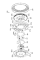
図2および図3に示すように、リクライニング装置20は、上述した両フレーム21,22に加えて、外歯車23、内歯車24、回転軸25、ブッシュ26、連結部材27、スプリング28、押さえ部材29および蓋部材30を備えている。なお、図3では、両フレーム21,22の記載を省略している。
As shown in FIGS. 2 and 3, the reclining
図2〜図4に示すように、外歯車23は、略円環状に形成されるとともにその外周面には外歯23aが形成されている。また、外歯車23の第1フレーム21側の側面である一側面23bに対向する他側面23cには、中央部から同軸的に突出する円筒部23dと外縁近傍から突出する2つの凸部23eが形成されている。両凸部23eは回転中心を基準に対称に設けられている。また、外歯車23の一側面23bには、当該外歯車23を第1フレーム21に連結するための複数の円柱状の突起23fが設けられている。
As shown in FIGS. 2 to 4, the
図2、図3および図5に示すように、内歯車24は、略円環状に形成されておりその一側面24bの外縁には内歯24aが形成されている。この内歯24aは、外歯23aに噛合可能であり当該外歯23aよりも歯数が多くなるように形成されている。また、一側面24bに対向する他側面24cには、当該内歯車24を第2フレーム22に連結するための2つの円弧状の突出部24dと2つの円柱状の突起24eとが、回転中心を基準に対称であって軸方向に突出するようにそれぞれ設けられている。
As shown in FIGS. 2, 3 and 5, the
また、内歯車24の一側面24bには、両突出部24dに対向する部位にて当該両突出部24dの突出量に応じて円弧状に凹む2つの凹部24fが設けられている(図2参照)。両凹部24fは、外歯23aおよび内歯24aが噛合するとき両凸部23eが挿入し、外歯車23および内歯車24が相対回転するとき所定の相対回転位置で両凸部23eにそれぞれ当接するように形成されている。
In addition, the one
回転軸25は、外歯車23の円筒部23dに対して同軸的であって回転自在に嵌合するように形成されている。この回転軸25は、シートバック12をシートクッション11に対して傾動させるときに操作レバーの操作に応じて回転駆動されるものであり、回転軸25の内面には、操作レバーを連結するためのセレーションが形成されている。
The rotating
上述のように構成される外歯車23および内歯車24は、両凸部23eが対応する凹部24fにそれぞれ挿入するように外歯23aおよび内歯24aが噛合して連結されている。
The
ここで、両凹部24fは突出部24dの突出量に応じて凹み量が設定されているため、内歯車の凸部と外歯車の凹部の側壁とを当接させることで両歯車の相対回転を規制するための空間を両歯車間に設ける必要がないので、噛合時における外歯車23の他側面23cと内歯車24の他側面24cとの軸方向の離間距離が小さくなる。
Here, since the
そして、内歯車24の内周面24gには耐摩耗性に優れた円筒形のブッシュ26が嵌め込まれるとともに、このブッシュ26の内周面と外歯車23の円筒部23dの外周面との間には、両者に接触するように、連結部材27が挿入される。
A
連結部材27は、ブッシュ26の内周面と円筒部23dの外周面との間に配置されることで、外歯車23に対して内歯車24を偏心させ、外歯23aに内歯24aを噛合させるものである。外歯車23に嵌合される回転軸25は、連結部材27により、外歯23aと内歯24aとを噛合させ、外歯車23および内歯車24のいずれか一方を他方の歯車軸を中心に公転させる。この連結部材27にはスプリング28が係合されており、回転軸25に回転力が入力されない限り、当該回転軸25と内歯車24との相対運動を禁止するように連結部材27がスプリング28によって付勢されている。
The connecting
そして、円筒状の押さえ部材29を、その内縁部近傍にて外歯車23の外縁近傍に接触した状態でその外縁部にて内歯車24の外周面に嵌合させることで、当該押さえ部材29により外歯車23と内歯車24とが互いに近接するように付勢される。
Then, the cylindrical pressing
続いて、略円環状に形成された蓋部材30を、その円弧状の2つの係合穴30aと円状の2つの係合穴30bを内歯車24の両突出部24dおよび両突起24eにそれぞれ係合するとともにその中央の貫通穴から回転軸25の一端部を突出させるようにして、内歯車24に組み付ける。これにより、連結部材27等が内歯車24の内周面24gの内方に収容されることとなる。
Subsequently, the
そして、座部フレーム11aに連結される第1フレーム21と外歯車23とを連結するために、各突起23fを第1フレーム21の係合穴21aにそれぞれ係合させる。また、背部フレーム12aに連結される第2フレーム22と内歯車24とを連結するために、蓋部材30が係合された両突出部24dおよび両突起24eを第2フレーム22の係合穴22aにそれぞれ係合させる。
これにより、図2に示すリクライニング装置20が完成する。
Then, in order to connect the
Thereby, the
次に、リクライニング装置20における両歯車23,24の相対回転の規制について説明する。
シートバック12をシートクッション11に対して傾動させるために上記操作レバーの操作に応じて回転軸25が回転駆動するとき、この回転軸25の回転駆動に応じて外歯車23および内歯車24が相対回転し、シートバック12がシートクッション11に対して傾動する。
Next, regulation of relative rotation of both
When the
そして、両歯車23,24が上述した所定の相対回転位置に相当する位置まで相対回転すると、内歯車24の両凹部24fにそれぞれ挿入されている外歯車23の両凸部23eが当該凹部24fの側壁にそれぞれ当接するため、当該相対回転が規制されることとなる。
When the
このように、両凸部23eと両凹部24fがそれぞれ当接することで両歯車23,24の相対回転が規制されるので、1つずつ設けた凸部および凹部が当接する場合と比較して、凸部23eおよび凹部24fの当接時の衝撃が分散されて両歯車23,24に作用する負荷が低減される。
In this way, since the relative rotation of both
以上説明したように、本実施形態に係るリクライニング装置20では、外歯車23には他側面23cから突出する凸部23eが設けられている。内歯車24には他側面24cに円弧状の2つの突出部24dが設けられており、両突出部24dが第2フレーム22に係合することにより当該内歯車24が第2フレーム22に連結される。そして、内歯車24の一側面24bには、両突出部24dに対向する部位にて当該突出部24dの突出量に応じて円弧状に凹む2つの凹部24fが設けられており、両凹部24fは、外歯23aおよび内歯24aが噛合するとき凸部23eがそれぞれ挿入し、外歯車23および内歯車24が相対回転するとき所定の相対回転位置で凸部23eにそれぞれ当接することで両歯車23,24の相対回転を一定範囲内に規制するように形成される。
As described above, in the
これにより、内歯車24において、他側面24cの両突出部24dは当該内歯車24を第2フレーム22に係合するための係合部材として機能し、一側面24bの両凹部24fは上記所定の相対回転位置で外歯車23の両凸部23eに当接して両歯車23,24の相対回転を規制する規制部材として機能し得る。このように、係合部材として突出する両突出部24dの突出量に応じて規制部材としての両凹部24fの凹み量が設定されることにより、上述したような内歯車の凸部と外歯車の凹部の側壁とを当接させることで両歯車の相対回転を規制するための空間を両歯車間に設ける必要がないので、噛合時における外歯車23の他側面23cと内歯車24の他側面24cとの軸方向の離間距離が小さくなり、当該リクライニング装置20の軸方向の厚みを薄くすることができる。
Thereby, in the
また、本実施形態に係るリクライニング装置20では、外歯車23には、その回転中心を基準に上記凸部23eが対称に2つ設けられ、内歯車24には、上記所定の相対回転位置に応じて両凸部23eに当接する上記凹部24fが2つ一側面24bに設けられるとともにこれら両凹部24fにそれぞれ対向する他側面24cの部位に上記突出部24dが2つ設けられている。
Further, in the
これにより、2つの凸部23eと2つの凹部24fがそれぞれ当接することで両歯車23,24の相対回転が規制されるので、凸部23eおよび凹部24fの当接時の衝撃が分散されて両歯車23,24に作用する負荷を低減することができる。特に、両凸部23eおよび両凹部24fは、回転中心を基準に対称に形成されることとなるため、両歯車23,24の組付け作業に関する作業ミスをなくすだけでなく、歯車製造時の熱処理歪み等の影響が少なくなるので、両凸部および両凹部が非対称に製造される場合と比較して、当該リクライニング装置20の製造コストを低減することができる。
As a result, the relative rotation of the two
なお、本発明は上記実施形態に限定されるものではなく、以下のように具体化してもよく、その場合でも、上記実施形態と同等の作用・効果が得られる。
(1)外歯車23の凸部23eと内歯車24の突出部24dおよび凹部24fとはそれぞれ2つ回転中心を基準に対称に設けられることに限らず、回転中心を基準にそれぞれ3つ以上対称に設けられてもよい。また、両歯車23,24の相対回転規制時の負荷が小さい場合には、外歯車23の凸部23eと内歯車24の突出部24dおよび凹部24fとを1つずつ設けるようにしてもよい。
In addition, this invention is not limited to the said embodiment, You may actualize as follows, and even in that case, an effect | action and effect equivalent to the said embodiment are acquired.
(1) The
(2)第1フレーム21および第2フレーム22は、座部フレーム11aおよび背部フレーム12aの一部であってもよい。
(2) The
10…車両用シート
11…シートクッション
12…シートバック
20…リクライニング装置
21…第1フレーム
22…第2フレーム
23…外歯車
23a…外歯
23b…一側面
23c…他側面
23e…凸部
24…内歯車
24a…内歯
24b…一側面
24c…他側面
24d…突出部
24f…凹部
25…回転軸
DESCRIPTION OF
Claims (2)
シートクッションおよびシートバックのいずれか一方に固定される第1フレームと、
シートクッションおよびシートバックの他方に固定される第2フレームと、
前記第1フレームに連結されて外周面に外歯が形成される外歯車であって、前記第1フレームに連結される側とは反対側の側面から軸方向に突出する凸部が設けられる外歯車と、
前記外歯に噛合可能であり当該外歯よりも歯数が多い内歯が形成される内歯車であって、前記内歯が形成される側の側面である一側面に対して対向する他側面から円弧状に突出する突出部にて前記第2フレームに係合することにより当該第2フレームに連結される内歯車と、
前記外歯車に同軸的かつ回転自在に嵌合するとともに、前記外歯車および前記内歯車のいずれか一方を他方の歯車軸を中心に公転させる回転軸と、を備え、
前記内歯車の前記一側面には、前記突出部に対向する部位にて当該突出部の突出量に応じて円弧状に凹む凹部が設けられており、
前記凹部は、前記外歯および前記内歯が噛合するとき前記凸部が挿入し、前記外歯車および前記内歯車が相対回転するとき所定の相対回転位置で前記凸部に当接することで前記相対回転を一定範囲内に規制するように形成されることを特徴とするリクライニング装置。 A seat reclining device that tiltably holds a seat back with respect to a seat cushion,
A first frame fixed to either the seat cushion or the seat back;
A second frame fixed to the other of the seat cushion and the seat back;
An external gear that is connected to the first frame and has external teeth formed on an outer peripheral surface thereof, and is provided with a convex portion that protrudes in an axial direction from a side surface opposite to the side connected to the first frame. Gears,
An internal gear that is capable of meshing with the external teeth and that has internal teeth with a larger number of teeth than the external teeth, and that is opposed to one side that is the side on the side where the internal teeth are formed. An internal gear coupled to the second frame by engaging the second frame with a projecting portion projecting in an arc from
A rotary shaft that is coaxially and rotatably fitted to the external gear and revolves around one of the external gear and the internal gear about the other gear shaft;
The one side surface of the internal gear is provided with a concave portion that is recessed in an arc shape in accordance with the protruding amount of the protruding portion at a portion facing the protruding portion.
The concave portion is inserted into the convex portion when the external teeth and the internal gear mesh with each other, and contacts the convex portion at a predetermined relative rotational position when the external gear and the internal gear rotate relative to each other. A reclining device formed to restrict rotation within a certain range.
前記内歯車には、前記所定の相対回転位置に応じて前記両凸部に当接する前記凹部が2つ設けられるとともにこれら両凹部にそれぞれ対向する前記他側面の部位に前記突出部が2つ設けられることを特徴とする請求項1に記載のリクライニング装置。 The external gear is provided with two convex portions symmetrically with respect to the rotation center thereof,
The internal gear is provided with two concave portions that contact the convex portions according to the predetermined relative rotational position, and two protruding portions that are provided on the other side surface respectively facing the concave portions. The reclining device according to claim 1, wherein
Priority Applications (1)
| Application Number | Priority Date | Filing Date | Title |
|---|---|---|---|
| JP2009107750A JP5262957B2 (en) | 2009-04-27 | 2009-04-27 | Reclining device |
Applications Claiming Priority (1)
| Application Number | Priority Date | Filing Date | Title |
|---|---|---|---|
| JP2009107750A JP5262957B2 (en) | 2009-04-27 | 2009-04-27 | Reclining device |
Publications (2)
| Publication Number | Publication Date |
|---|---|
| JP2010253101A JP2010253101A (en) | 2010-11-11 |
| JP5262957B2 true JP5262957B2 (en) | 2013-08-14 |
Family
ID=43314719
Family Applications (1)
| Application Number | Title | Priority Date | Filing Date |
|---|---|---|---|
| JP2009107750A Active JP5262957B2 (en) | 2009-04-27 | 2009-04-27 | Reclining device |
Country Status (1)
| Country | Link |
|---|---|
| JP (1) | JP5262957B2 (en) |
Families Citing this family (6)
| Publication number | Priority date | Publication date | Assignee | Title |
|---|---|---|---|---|
| DE102011051990A1 (en) * | 2011-07-20 | 2013-01-24 | C. Rob. Hammerstein Gmbh & Co. Kg | Seat fitting for a motor vehicle seat |
| CN104583002B (en) | 2013-06-27 | 2017-03-01 | 达世株式会社 | Seat angle adjuster |
| DE112014000343B4 (en) | 2013-06-27 | 2022-08-04 | Das Co., Ltd | Folding device for a vehicle seat |
| JP6431254B2 (en) * | 2013-09-30 | 2018-11-28 | トヨタ紡織株式会社 | Recliner |
| KR102046900B1 (en) | 2013-12-02 | 2019-11-21 | 주식회사 다스 | Recliner of vehicle seet |
| JP6807708B2 (en) | 2016-10-31 | 2021-01-06 | 株式会社Tf−Metal | Vehicle seat reclining device |
Family Cites Families (4)
| Publication number | Priority date | Publication date | Assignee | Title |
|---|---|---|---|---|
| JP3946948B2 (en) * | 2000-10-06 | 2007-07-18 | シロキ工業株式会社 | Reclining device |
| JP2004188043A (en) * | 2002-12-13 | 2004-07-08 | Shiroki Corp | Reclining device |
| JP5184762B2 (en) * | 2006-06-08 | 2013-04-17 | シロキ工業株式会社 | Reclining device |
| JP5086735B2 (en) * | 2007-08-13 | 2012-11-28 | シロキ工業株式会社 | Reclining device |
-
2009
- 2009-04-27 JP JP2009107750A patent/JP5262957B2/en active Active
Also Published As
| Publication number | Publication date |
|---|---|
| JP2010253101A (en) | 2010-11-11 |
Similar Documents
| Publication | Publication Date | Title |
|---|---|---|
| JP5262957B2 (en) | Reclining device | |
| JP5046682B2 (en) | Vehicle seat reclining device | |
| JP4784086B2 (en) | Vehicle seat reclining device | |
| JP2009201783A (en) | Seat reclining apparatus for vehicle | |
| JP2006020782A (en) | Reclining adjuster | |
| JP2014239721A (en) | Reclining device | |
| US20120306254A1 (en) | Reclining device | |
| JP2003009978A (en) | Seat reclining device | |
| WO2012001769A1 (en) | Seat reclining device for tiltably holding seat back | |
| JP2011087843A (en) | Reclining mechanism | |
| US20070295161A1 (en) | Reclining device incorporation by reference | |
| JP2009138758A (en) | Rotation stopper | |
| JP2019127210A (en) | Reclining device | |
| JP5424859B2 (en) | Vehicle seat reclining device | |
| JP7244752B2 (en) | reclining device | |
| JP5467908B2 (en) | Vehicle seat reclining device | |
| JP7479305B2 (en) | Reclining device | |
| JP2011207253A (en) | Reclining device | |
| JP2002291563A (en) | Seat reclining device for vehicle | |
| JP7417050B2 (en) | reclining device | |
| JP7460893B2 (en) | reclining device | |
| JP2003019052A (en) | Reclining device | |
| JP2011200476A (en) | Seat reclining device for vehicle | |
| JP2022172593A (en) | reclining device | |
| JP2006246987A (en) | Car sheet reclining device and its production method |
Legal Events
| Date | Code | Title | Description |
|---|---|---|---|
| A621 | Written request for application examination |
Free format text: JAPANESE INTERMEDIATE CODE: A621 Effective date: 20110802 |
|
| A977 | Report on retrieval |
Free format text: JAPANESE INTERMEDIATE CODE: A971007 Effective date: 20130327 |
|
| TRDD | Decision of grant or rejection written | ||
| A01 | Written decision to grant a patent or to grant a registration (utility model) |
Free format text: JAPANESE INTERMEDIATE CODE: A01 Effective date: 20130402 |
|
| A61 | First payment of annual fees (during grant procedure) |
Free format text: JAPANESE INTERMEDIATE CODE: A61 Effective date: 20130415 |
|
| R150 | Certificate of patent or registration of utility model |
Free format text: JAPANESE INTERMEDIATE CODE: R150 Ref document number: 5262957 Country of ref document: JP Free format text: JAPANESE INTERMEDIATE CODE: R150 |
|
| R250 | Receipt of annual fees |
Free format text: JAPANESE INTERMEDIATE CODE: R250 |
|
| R250 | Receipt of annual fees |
Free format text: JAPANESE INTERMEDIATE CODE: R250 |
|
| R250 | Receipt of annual fees |
Free format text: JAPANESE INTERMEDIATE CODE: R250 |
|
| R250 | Receipt of annual fees |
Free format text: JAPANESE INTERMEDIATE CODE: R250 |