JP5259657B2 - Constrained hopping in wireless communication systems - Google Patents
Constrained hopping in wireless communication systems Download PDFInfo
- Publication number
- JP5259657B2 JP5259657B2 JP2010173703A JP2010173703A JP5259657B2 JP 5259657 B2 JP5259657 B2 JP 5259657B2 JP 2010173703 A JP2010173703 A JP 2010173703A JP 2010173703 A JP2010173703 A JP 2010173703A JP 5259657 B2 JP5259657 B2 JP 5259657B2
- Authority
- JP
- Japan
- Prior art keywords
- subband
- transmission
- channel quality
- band
- sub
- Prior art date
- Legal status (The legal status is an assumption and is not a legal conclusion. Google has not performed a legal analysis and makes no representation as to the accuracy of the status listed.)
- Expired - Fee Related
Links
- 238000004891 communication Methods 0.000 title claims description 26
- 230000005540 biological transmission Effects 0.000 claims description 54
- 238000000034 method Methods 0.000 claims description 41
- 238000013468 resource allocation Methods 0.000 claims description 4
- 230000008569 process Effects 0.000 description 17
- 230000004044 response Effects 0.000 description 15
- 230000006870 function Effects 0.000 description 12
- 238000012545 processing Methods 0.000 description 6
- 238000007493 shaping process Methods 0.000 description 5
- 238000010586 diagram Methods 0.000 description 4
- 238000013461 design Methods 0.000 description 3
- 238000012549 training Methods 0.000 description 3
- 230000003213 activating effect Effects 0.000 description 2
- 238000013459 approach Methods 0.000 description 2
- 239000000969 carrier Substances 0.000 description 2
- 238000012937 correction Methods 0.000 description 2
- 238000013507 mapping Methods 0.000 description 2
- 230000003287 optical effect Effects 0.000 description 2
- 230000000737 periodic effect Effects 0.000 description 2
- 230000008054 signal transmission Effects 0.000 description 2
- 230000003068 static effect Effects 0.000 description 2
- KLDZYURQCUYZBL-UHFFFAOYSA-N 2-[3-[(2-hydroxyphenyl)methylideneamino]propyliminomethyl]phenol Chemical compound OC1=CC=CC=C1C=NCCCN=CC1=CC=CC=C1O KLDZYURQCUYZBL-UHFFFAOYSA-N 0.000 description 1
- RYGMFSIKBFXOCR-UHFFFAOYSA-N Copper Chemical compound [Cu] RYGMFSIKBFXOCR-UHFFFAOYSA-N 0.000 description 1
- 230000008901 benefit Effects 0.000 description 1
- 230000008859 change Effects 0.000 description 1
- 230000001427 coherent effect Effects 0.000 description 1
- 238000010924 continuous production Methods 0.000 description 1
- 229910052802 copper Inorganic materials 0.000 description 1
- 239000010949 copper Substances 0.000 description 1
- 238000013500 data storage Methods 0.000 description 1
- 201000001098 delayed sleep phase syndrome Diseases 0.000 description 1
- 208000033921 delayed sleep phase type circadian rhythm sleep disease Diseases 0.000 description 1
- 230000000694 effects Effects 0.000 description 1
- 238000005516 engineering process Methods 0.000 description 1
- 230000006872 improvement Effects 0.000 description 1
- 238000007726 management method Methods 0.000 description 1
- 238000012986 modification Methods 0.000 description 1
- 230000004048 modification Effects 0.000 description 1
- 230000010363 phase shift Effects 0.000 description 1
Images

Classifications
-
- H—ELECTRICITY
- H04—ELECTRIC COMMUNICATION TECHNIQUE
- H04B—TRANSMISSION
- H04B1/00—Details of transmission systems, not covered by a single one of groups H04B3/00 - H04B13/00; Details of transmission systems not characterised by the medium used for transmission
- H04B1/69—Spread spectrum techniques
- H04B1/713—Spread spectrum techniques using frequency hopping
-
- H—ELECTRICITY
- H04—ELECTRIC COMMUNICATION TECHNIQUE
- H04B—TRANSMISSION
- H04B1/00—Details of transmission systems, not covered by a single one of groups H04B3/00 - H04B13/00; Details of transmission systems not characterised by the medium used for transmission
- H04B1/69—Spread spectrum techniques
- H04B1/707—Spread spectrum techniques using direct sequence modulation
- H04B1/7097—Interference-related aspects
- H04B1/711—Interference-related aspects the interference being multi-path interference
- H04B1/7115—Constructive combining of multi-path signals, i.e. RAKE receivers
-
- H—ELECTRICITY
- H04—ELECTRIC COMMUNICATION TECHNIQUE
- H04B—TRANSMISSION
- H04B7/00—Radio transmission systems, i.e. using radiation field
- H04B7/02—Diversity systems; Multi-antenna system, i.e. transmission or reception using multiple antennas
- H04B7/022—Site diversity; Macro-diversity
- H04B7/024—Co-operative use of antennas of several sites, e.g. in co-ordinated multipoint or co-operative multiple-input multiple-output [MIMO] systems
-
- H—ELECTRICITY
- H04—ELECTRIC COMMUNICATION TECHNIQUE
- H04L—TRANSMISSION OF DIGITAL INFORMATION, e.g. TELEGRAPHIC COMMUNICATION
- H04L25/00—Baseband systems
- H04L25/02—Details ; arrangements for supplying electrical power along data transmission lines
- H04L25/0202—Channel estimation
- H04L25/0204—Channel estimation of multiple channels
-
- H—ELECTRICITY
- H04—ELECTRIC COMMUNICATION TECHNIQUE
- H04L—TRANSMISSION OF DIGITAL INFORMATION, e.g. TELEGRAPHIC COMMUNICATION
- H04L25/00—Baseband systems
- H04L25/02—Details ; arrangements for supplying electrical power along data transmission lines
- H04L25/0202—Channel estimation
- H04L25/0224—Channel estimation using sounding signals
- H04L25/0226—Channel estimation using sounding signals sounding signals per se
-
- H—ELECTRICITY
- H04—ELECTRIC COMMUNICATION TECHNIQUE
- H04L—TRANSMISSION OF DIGITAL INFORMATION, e.g. TELEGRAPHIC COMMUNICATION
- H04L5/00—Arrangements affording multiple use of the transmission path
- H04L5/0001—Arrangements for dividing the transmission path
- H04L5/0014—Three-dimensional division
- H04L5/0023—Time-frequency-space
-
- H—ELECTRICITY
- H04—ELECTRIC COMMUNICATION TECHNIQUE
- H04L—TRANSMISSION OF DIGITAL INFORMATION, e.g. TELEGRAPHIC COMMUNICATION
- H04L5/00—Arrangements affording multiple use of the transmission path
- H04L5/003—Arrangements for allocating sub-channels of the transmission path
- H04L5/0037—Inter-user or inter-terminal allocation
- H04L5/0039—Frequency-contiguous, i.e. with no allocation of frequencies for one user or terminal between the frequencies allocated to another
-
- H—ELECTRICITY
- H04—ELECTRIC COMMUNICATION TECHNIQUE
- H04L—TRANSMISSION OF DIGITAL INFORMATION, e.g. TELEGRAPHIC COMMUNICATION
- H04L5/00—Arrangements affording multiple use of the transmission path
- H04L5/003—Arrangements for allocating sub-channels of the transmission path
- H04L5/0048—Allocation of pilot signals, i.e. of signals known to the receiver
-
- H—ELECTRICITY
- H04—ELECTRIC COMMUNICATION TECHNIQUE
- H04L—TRANSMISSION OF DIGITAL INFORMATION, e.g. TELEGRAPHIC COMMUNICATION
- H04L5/00—Arrangements affording multiple use of the transmission path
- H04L5/003—Arrangements for allocating sub-channels of the transmission path
- H04L5/0053—Allocation of signalling, i.e. of overhead other than pilot signals
- H04L5/0057—Physical resource allocation for CQI
-
- H—ELECTRICITY
- H04—ELECTRIC COMMUNICATION TECHNIQUE
- H04L—TRANSMISSION OF DIGITAL INFORMATION, e.g. TELEGRAPHIC COMMUNICATION
- H04L5/00—Arrangements affording multiple use of the transmission path
- H04L5/003—Arrangements for allocating sub-channels of the transmission path
- H04L5/0058—Allocation criteria
- H04L5/006—Quality of the received signal, e.g. BER, SNR, water filling
-
- H—ELECTRICITY
- H04—ELECTRIC COMMUNICATION TECHNIQUE
- H04B—TRANSMISSION
- H04B7/00—Radio transmission systems, i.e. using radiation field
- H04B7/02—Diversity systems; Multi-antenna system, i.e. transmission or reception using multiple antennas
- H04B7/04—Diversity systems; Multi-antenna system, i.e. transmission or reception using multiple antennas using two or more spaced independent antennas
- H04B7/0413—MIMO systems
-
- H—ELECTRICITY
- H04—ELECTRIC COMMUNICATION TECHNIQUE
- H04L—TRANSMISSION OF DIGITAL INFORMATION, e.g. TELEGRAPHIC COMMUNICATION
- H04L1/00—Arrangements for detecting or preventing errors in the information received
- H04L1/0001—Systems modifying transmission characteristics according to link quality, e.g. power backoff
- H04L1/0023—Systems modifying transmission characteristics according to link quality, e.g. power backoff characterised by the signalling
- H04L1/0028—Formatting
- H04L1/0029—Reduction of the amount of signalling, e.g. retention of useful signalling or differential signalling
-
- H—ELECTRICITY
- H04—ELECTRIC COMMUNICATION TECHNIQUE
- H04L—TRANSMISSION OF DIGITAL INFORMATION, e.g. TELEGRAPHIC COMMUNICATION
- H04L25/00—Baseband systems
- H04L25/02—Details ; arrangements for supplying electrical power along data transmission lines
- H04L25/0202—Channel estimation
- H04L25/0224—Channel estimation using sounding signals
- H04L25/0228—Channel estimation using sounding signals with direct estimation from sounding signals
- H04L25/023—Channel estimation using sounding signals with direct estimation from sounding signals with extension to other symbols
- H04L25/0232—Channel estimation using sounding signals with direct estimation from sounding signals with extension to other symbols by interpolation between sounding signals
-
- H—ELECTRICITY
- H04—ELECTRIC COMMUNICATION TECHNIQUE
- H04L—TRANSMISSION OF DIGITAL INFORMATION, e.g. TELEGRAPHIC COMMUNICATION
- H04L5/00—Arrangements affording multiple use of the transmission path
- H04L5/003—Arrangements for allocating sub-channels of the transmission path
- H04L5/0044—Allocation of payload; Allocation of data channels, e.g. PDSCH or PUSCH
-
- H—ELECTRICITY
- H04—ELECTRIC COMMUNICATION TECHNIQUE
- H04L—TRANSMISSION OF DIGITAL INFORMATION, e.g. TELEGRAPHIC COMMUNICATION
- H04L5/00—Arrangements affording multiple use of the transmission path
- H04L5/0091—Signalling for the administration of the divided path, e.g. signalling of configuration information
- H04L5/0094—Indication of how sub-channels of the path are allocated
Landscapes
- Engineering & Computer Science (AREA)
- Signal Processing (AREA)
- Computer Networks & Wireless Communication (AREA)
- Power Engineering (AREA)
- Quality & Reliability (AREA)
- Mobile Radio Communication Systems (AREA)
Description
本開示は、一般に、通信システムに関し、特に、無線通信システムにおける制約されたホッピング及びチャネル推定に関する。 The present disclosure relates generally to communication systems, and more particularly to constrained hopping and channel estimation in wireless communication systems.
デジタル通信では、情報はビットと呼ばれるデジタルデータに変換される。送信機は、入力されたビットストリームを、通信チャネルによる送信用の波形へ変調する。受信機は、受信した波形をビットに復調し、もって、情報を復元する。理想的な通信システムでは、受信されたデータは、送信されたデータと一致するだろう。しかしながら、実際には、送信機から受信機への、通信チャネルによるデータ送信の間に、歪み又は雑音がもたらされうる。歪みが顕著な場合、この情報は、受信機において受信されたデータから復元できないかもしれない。 In digital communication, information is converted into digital data called bits. The transmitter modulates the input bit stream into a waveform for transmission over the communication channel. The receiver demodulates the received waveform into bits, thereby restoring information. In an ideal communication system, the received data will match the transmitted data. In practice, however, distortion or noise can be introduced during data transmission over the communication channel from the transmitter to the receiver. If the distortion is significant, this information may not be recoverable from the data received at the receiver.
直交周波数分割多重化(OFDM)は、システム帯域幅全体を、多くの(N個の)直交サブキャリアへ効果的に分割する変調技術である。このサブキャリアはまた一般に、トーン、ビン、及び周波数チャネルとも称される。 Orthogonal frequency division multiplexing (OFDM) is a modulation technique that effectively divides the entire system bandwidth into many (N) orthogonal subcarriers. This subcarrier is also commonly referred to as a tone, bin, and frequency channel.
OFDMは、様々な通信システム内で広く使用される。例えば、直交周波数分割多元接続(OFDMA)システムは、OFDMを利用し、多数のユーザをサポートすることができる。N個のサブキャリアは、システム設計に依存して、様々な手法のデータ送信及びパイロット送信に使用されうる。例えば、OFDMAシステムは、N個のサブキャリアを多数のバラバラなサブキャリアのグループに分割し、各サブキャリアグループを異なるユーザに割り当てる。そして、多数のユーザは、自分に割り当てられたサブキャリアグループによって同時にサポートされうる。 OFDM is widely used in various communication systems. For example, Orthogonal Frequency Division Multiple Access (OFDMA) systems can utilize OFDM and support a large number of users. The N subcarriers may be used for various methods of data transmission and pilot transmission, depending on the system design. For example, an OFDMA system divides N subcarriers into a number of disjoint subcarrier groups and assigns each subcarrier group to a different user. A large number of users can be simultaneously supported by the subcarrier groups assigned to them.
データは、送信中にしばしば歪められる。歪みの効果を緩和するために、チャネル推定は、データ送信中にデータにもたらされた歪みを補うために使用される1つの技術である。チャンネル推定は、広帯域パイロット信号の使用によってしばしば行われる。ここで、利用可能なトーン全体の一部が、パイロットシンボルのために確保される。これらのパイロットシンボルは、一般に、最適なパフォーマンスのために、帯域全体にわたって等間隔とされる。次に、受信機では、歪みを加えられた状態で受信されたデータを処理することによって、チャネル応答を推定することができる。例えば複数入力複数出力通信システム(MIMO)におけるユーザのようなユーザが、複数のチャネルを推定する必要があるのであれば、システムオーバヘッドが増加する。例えば、4アンテナMIMO送信では、3つの追加の広帯域パイロット信号を送信する必要がある。 Data is often distorted during transmission. In order to mitigate the effects of distortion, channel estimation is one technique used to compensate for distortion introduced to the data during data transmission. Channel estimation is often done through the use of wideband pilot signals. Here, some of the total available tones are reserved for pilot symbols. These pilot symbols are generally equally spaced throughout the band for optimal performance. The receiver can then estimate the channel response by processing the received data in a distorted state. For example, if a user such as a user in a multiple-input multiple-output communication system (MIMO) needs to estimate multiple channels, the system overhead increases. For example, in 4-antenna MIMO transmission, three additional wideband pilot signals need to be transmitted.
典型的なMIMOシステムは、データ送信のために、複数の(NT個の)送信アンテナと、複数の(NR個の)受信アンテナとを用い、(NT,NR)システムと称される。NT個の送信アンテナ及びNR個の受信アンテナによって形成されたMIMOチャネルは、NS個の空間チャネルに分解される。ここで、以下に示すように、NS≦min{NT,NR}である。NS個のデータストリームは、NS個の空間のチャネルによって送信されうる。複数の送信アンテナ及び複数の受信アンテナによって形成されたNS個の空間チャネルがデータ送信のために使用されるのであれば、MIMOシステムは、増加された送信能力を提供することができる。 A typical MIMO system uses multiple (N T ) transmit antennas and multiple (N R ) receive antennas for data transmission and is referred to as an (N T , N R ) system. The The MIMO channel formed by N T transmit antennas and N R receive antennas is broken down into N S spatial channels. Here, as shown below, N S ≦ min {N T , N R} is. N S data streams may be transmitted over the N S spatial channels. A MIMO system can provide increased transmission capability if NS spatial channels formed by multiple transmit antennas and multiple receive antennas are used for data transmission.
個々の空間チャネルの送信能力は、その空間チャネルによって達成される信号対雑音及び干渉比(SINR)に依存する。NS個の空間チャネルのSINRは、チャネル条件に依存し、更に、データストリームが受信機において復元される方式にも依存しうる。1つの従来のMIMOシステムでは、送信機が、静的MIMOチャネルのモデルに基づいて選択されたレートに従って各データストリームを符号化し、変調し、そして送信する。モデルが正確であり、かつ、MIMOチャネルが比較的静的(つまり、時間とともにあまり変化しないので)であれば、良好な性能を得ることができる。別の従来のMIMOシステムでは、受信機が、MIMOチャネルを推定し、このチャネル推定に基づいて、各空間チャネルに適切なレートを選択し、NS個の空間チャネル用に選択されたNS個のレートを送信機に送る。そして、送信機は、選択されたレートに従ってNS個のデータストリームを処理し、これらストリームを、NS個の空間チャネルに送信する。このシステムの性能は、MIMOチャネルの特徴と、チャネル推定の精度とに依存する。 The transmission capability of an individual spatial channel depends on the signal to noise and interference ratio (SINR) achieved by that spatial channel. The SINR of the N S spatial channels depends on the channel conditions and may also depend on the manner in which the data stream is recovered at the receiver. In one conventional MIMO system, a transmitter encodes, modulates, and transmits each data stream according to a rate selected based on a model of a static MIMO channel. Good performance can be obtained if the model is accurate and the MIMO channel is relatively static (ie, it does not change much over time). In another conventional MIMO system, a receiver estimates the MIMO channel based on this channel estimation, the N S to select an appropriate rate for each spatial channel, selected for the N S spatial channels Send the rate to the transmitter. The transmitter processes the N S data streams in accordance with the selected rate, these streams are transmitted to the N S spatial channels. The performance of this system depends on the characteristics of the MIMO channel and the accuracy of the channel estimation.
ユーザのシンボルが、全帯域にわたってホッピングパターンで送信される場合、チャネル推定値は、全帯域にわたって実行される必要がある。これは、広帯域パイロット信号が、推定された全てのチャネルに必要とされるとき、MIMOユーザの場合に悪化する。更に、全帯域にわたってユーザを活動させることは、チャネルバリエーションを縮小し、もって、マルチユーザーゲインを減少する。 If the user's symbols are transmitted in a hopping pattern over the entire band, channel estimates need to be performed over the entire band. This is exacerbated for MIMO users when wideband pilot signals are required for all estimated channels. Furthermore, activating users across the entire band reduces channel variation and thus reduces multi-user gain.
従って、利用可能な周波数帯域を介してユーザを活動させることはオーバヘッドを増加させる。更に、ユーザを、好ましいチャネル条件にスケジュールしない。従って、リソースを割り当てるためのより効率的な方法及びシステムに対するニーズがある。 Thus, activating users over the available frequency band increases overhead. In addition, users are not scheduled for preferred channel conditions. Thus, there is a need for more efficient methods and systems for allocating resources.
本願は、本明細書に参照によってその全体が組み込まれ、「Contiguous Hopping in an OFDMA Communication System」と題された2005年12月22日に出願の米国仮特許出願60/638,494からの35U.S.C 119条(e)の利益を要求する。 This application is incorporated by reference herein in its entirety and is 35 U.S. from US Provisional Patent Application 60 / 638,494, filed December 22, 2005, entitled “Contiguous Hopping in an OFDMA Communication System”. S. C 119 (e) profit is required.
ある局面では、与えられた周波数帯域上で動作する無線通信システムにおいて、チャネル推定のための方法は、周波数帯域のうちの1より多いサブ帯域において、複数のパイロット信号を受信することと、1つのサブ帯域について、そのサブ帯域で受信された複数のパイロット信号のうちの幾つかに基づいて、チャネル応答を推定することとを備える。 In an aspect, in a wireless communication system operating on a given frequency band, a method for channel estimation includes receiving a plurality of pilot signals in more than one subband of the frequency band, and one Estimating a channel response based on some of the plurality of pilot signals received in the subband.
他の局面では、与えられた周波数帯域上で動作する無線通信システムにおいて、送信のためのリソース割当方法は、単一のサブ帯域でユーザに送信するのが好ましいか、あるいは1より多いサブ帯域でユーザに送信するのが好ましいかを判定することを備える。ここで、各サブ帯域は、他のサブ帯域に関してオーバラップしないサブキャリアを含む。リソース割当方法は更に、この判定に基づいて、送信を、単一のサブ帯域内で引き起こるように割り当てるか、あるいは、1より多いサブ帯域内で動作するように割り当てることを備える。 In another aspect, in a wireless communication system operating on a given frequency band, the resource allocation method for transmission is preferably transmitted to the user in a single subband or in more than one subband Determining whether it is preferable to transmit to the user. Here, each subband includes subcarriers that do not overlap with respect to other subbands. The resource allocation method further comprises allocating transmissions to occur within a single subband based on this determination, or allocating to operate within more than one subband.
他の局面は、上記の機能及び他の構成を提供する手段と、同様の結果を生む方法とを含みうる。 Other aspects may include means for providing the above functions and other configurations and methods that produce similar results.
同一参照番号が同一要素を示す添付図面を参照して、様々な実施形態をより詳細に説明する。 Various embodiments are described in more detail with reference to the accompanying drawings, wherein like reference numerals indicate like elements.
従って、説明する実施形態は、1又は複数のサブ帯域に分割された周波数帯域内にユーザをスケジュールし、かつ、各ユーザによって1又は複数のサブ帯域内で受信されたパイロット信号に基づいて、チャネル応答を推定する。幾つかの局面では、興味のあるサブキャリアが、サブ帯域の端部近くにある場合、近隣のサブ帯域内で受信されたパイロット信号のうちの少なくとも一部が、チャネル応答を推定するために利用されうる。 Thus, the described embodiment schedules users in a frequency band that is divided into one or more subbands and channels based on pilot signals received by each user in one or more subbands. Estimate the response. In some aspects, if the subcarrier of interest is near the end of a subband, at least some of the pilot signals received in neighboring subbands are utilized to estimate the channel response Can be done.
説明する実施形態はまた、無線デバイスの送信のためのリソース割当を提供する。周波数帯域は、少なくとも2つのサブ帯域へ分割される。これらは隣接しているかも、あるいは隣接していないかもしれない。所定のユーザとの間で、単一のサブ帯域で送信するのが好ましいか、あるいは1より多いサブ帯域で送信するのが好ましいかが判定される。この送信は、単一のサブ帯域内で引き起こるように割り当てられるか、あるいは、1より多いサブ帯域内で動作するように割り当てられる。 The described embodiments also provide resource allocation for transmission of wireless devices. The frequency band is divided into at least two subbands. They may or may not be adjacent. It is determined whether it is preferable to transmit to a given user in a single subband, or to transmit in more than one subband. This transmission is assigned to occur within a single subband, or is assigned to operate within more than one subband.
下記の説明では、実施形態は、フローチャート、フロー図、構成図、あるいはブロック図として示される処理として説明されうる。フローチャートは動作を、連続的な処理として説明するかもしれないが、動作の多くは、並行して又は同時に実行することができる。更に、動作の順序が再調整されうる。その動作が完了すると処理は終了する。処理は、方法、機能、手順、サブルーチン、サブプログラム等に相当するかもしれない。処理が機能に相当する場合、その終了は、呼出し機能あるいは主機能への機能のリターンに相当する。 In the following description, the embodiments may be described as a process shown as a flowchart, a flow diagram, a configuration diagram, or a block diagram. Although a flowchart may describe the operations as a continuous process, many of the operations can be performed in parallel or concurrently. Furthermore, the order of operations can be readjusted. When the operation is completed, the process ends. A process may correspond to a method, function, procedure, subroutine, subprogram, and the like. If the process corresponds to a function, the end corresponds to the return of the function to the calling function or the main function.
本明細書に記載するように、用語「通信チャネル」は、無線通信チャネル及びワイヤーライン通信チャネルの両方を指す。無線通信チャネルの例は、ラジオ、衛星、及び音響通信チャネルである。ワイヤーライン通信チャネルの例は、限定される訳ではないが、光、銅、あるいは他の伝導性のワイヤ又は媒体を含む。用語「ルックアップテーブル」は、データベース又は様々な記憶媒体内のデータを指す。記憶媒体は、読取専用メモリ(ROM)、ランダムアクセスメモリ(RAM)、磁気ディスク記憶媒体、光記憶媒体、フラッシュメモリデバイス、及び/又はその他、情報を格納するための計算機読取可能媒体を含むデータ格納用の1又は複数のデバイスを表しうる。用語「計算機読取可能媒体」は、限定される訳ではないが、ポータブル又は固定式の記憶デバイス、光記憶デバイス、無線チャネル、及び、命令及び/又はデータを格納、包含、あるいは搬送することが可能なその他様々な媒体を含む。更に、説明の目的のために、実施形態は、直交周波数分割多重(OFDM)システムに関して記述される。しかしながら、本発明は、チャネル推定を必要とするその他のタイプのシステムに適用可能であることも良く理解されるであろう。 As described herein, the term “communication channel” refers to both wireless and wireline communication channels. Examples of wireless communication channels are radio, satellite, and acoustic communication channels. Examples of wireline communication channels include, but are not limited to, light, copper, or other conductive wires or media. The term “lookup table” refers to data in a database or various storage media. The storage medium is a data storage including read only memory (ROM), random access memory (RAM), magnetic disk storage medium, optical storage medium, flash memory device, and / or other computer readable medium for storing information. One or more devices may be represented. The term “computer-readable medium” includes, but is not limited to, a portable or fixed storage device, optical storage device, wireless channel, and instructions and / or data that can be stored, contained, or carried. Various other media. Further, for illustrative purposes, embodiments are described with reference to an orthogonal frequency division multiplexing (OFDM) system. However, it will be well understood that the present invention is applicable to other types of systems that require channel estimation.
OFDMは、周知のマルチキャリア通信技術の例である。一般に、OFDMは、異なる周波数において同時に送信される多数のサブ信号へ信号を分割するデジタル変調技術である。OFDMは、並行して送信される多くのサブチャネルにチャネルを分割するために、オーバラップした直交信号を用いる。OFDMは、低品質なチャネルによる高データレート送信を可能にするので、OFDMは、高速無線ローカルエリアネットワーク(LAN)内のような多くの無線アプリケーションにおいて成功している。 OFDM is an example of a well-known multicarrier communication technique. In general, OFDM is a digital modulation technique that divides a signal into multiple sub-signals that are transmitted simultaneously at different frequencies. OFDM uses overlapping orthogonal signals to divide the channel into many subchannels that are transmitted in parallel. Since OFDM enables high data rate transmission over low quality channels, OFDM has been successful in many wireless applications such as in high-speed wireless local area networks (LANs).
直交周波数分割多元接続(OFDMA)システムは、OFDMを利用し、多数のユーザを同時にサポートすることができる。操作周波数帯域幅は、信号の送信に使用され、複数の周波数サブキャリアへ細分割される。変調シンボル周期を適切に設計することによって、隣接した周波数サブキャリアは、互いにそれぞれ直交する。直交性は、機能の集合の特性であり、適切な間隔で設定されたセットのうちの任意の2つのメンバの積分が、ゼロになる。より具体的には、直交チャネル又は周波数は、互いに干渉しない。その結果、直交性は、受信機が、多重通信チャネルを介して並行して送信された他のサブキャリアを復調せずに、選択されたサブキャリアを復調することを可能にする。その結果、サブキャリア中の混線がなくなり、シンボル間干渉(inter-symbol-interference:ISI)は著しく低減される。 Orthogonal frequency division multiple access (OFDMA) systems utilize OFDM and can support multiple users simultaneously. The operating frequency bandwidth is used for signal transmission and is subdivided into a plurality of frequency subcarriers. By designing the modulation symbol period appropriately, adjacent frequency subcarriers are orthogonal to each other. Orthogonality is a property of a set of functions, where the integral of any two members of a set set at appropriate intervals is zero. More specifically, orthogonal channels or frequencies do not interfere with each other. As a result, orthogonality allows the receiver to demodulate selected subcarriers without demodulating other subcarriers transmitted in parallel over multiple communication channels. As a result, there is no cross-talk in subcarriers and inter-symbol-interference (ISI) is significantly reduced.
受信信号を調節するために使用することが可能なチャネル特性の正確な推定値が存在すれば、OFDMシステム性能は、コヒーレント復調を考慮することにより改善される場合がある。従って、パイロットシンボルパターン又はトレーニングシンボルとして知られているトレーニングシーケンスが、送信機によって送信される。このトレーニングシンボルは受信機に知られているので、受信機は、チャネル推定を実行することができる。 If there is an accurate estimate of the channel characteristics that can be used to adjust the received signal, OFDM system performance may be improved by considering coherent demodulation. Thus, a training sequence known as a pilot symbol pattern or training symbol is transmitted by the transmitter. Since this training symbol is known to the receiver, the receiver can perform channel estimation.
図1は、多くのユーザをサポートする典型的なOFDMAシステム100を示す。システム100は、多くの端末120のための通信をサポートする多くの基地局110を含んでいる。基地局は、端末と通信するために使用される固定局であり、アクセスポイント、ノードB、又はその他幾つかの用語を用いて称されうる。端末120は、一般に、システム全体にわたって分散しており、各端末は、固定式あるいは移動式でありうる。端末はまた、移動局、ユーザ機器(UE)、無線通信デバイス、あるいはその他幾つかの用語として称されうる。各端末はそれぞれ、任意の所定の瞬間において、順方向リンクで1又は複数の基地局と、及び/又は、逆方向リンクで1又は複数の基地局と通信しうる。これは、端末がアクティブであるか否か、ソフトハンドオフがサポートされているか否か、及び、端末がソフトハンドオフにあるか否かに依存する。順方向リンク(すなわち、ダウンリンク)は、基地局から端末への通信リンクを指す。また、逆方向リンク(すなわち、アップリンク)は、端末から基地局への通信リンクを指す。 FIG. 1 shows an exemplary OFDMA system 100 that supports many users. System 100 includes a number of base stations 110 that support communication for a number of terminals 120. A base station is a fixed station used to communicate with a terminal and may be referred to as an access point, Node B, or some other terminology. Terminals 120 are generally distributed throughout the system, and each terminal can be fixed or mobile. A terminal may also be referred to as a mobile station, user equipment (UE), a wireless communication device, or some other terminology. Each terminal may communicate with one or more base stations on the forward link and / or with one or more base stations on the reverse link at any given moment. This depends on whether the terminal is active, whether soft handoff is supported, and whether the terminal is in soft handoff. The forward link (ie, downlink) refers to the communication link from base stations to terminals. Also, the reverse link (ie, uplink) refers to the communication link from the terminal to the base station.
システムコントローラ130は、基地局110につながっており、(1)基地局110の調整及び制御、(2)これら基地局間のデータの経路付け、及び、(3)これら基地局によってサービス提供される端末のアクセス及び制御のような多くの機能を実行する。 The system controller 130 is connected to the base station 110 and (1) coordinates and controls the base station 110, (2) routes data between these base stations, and (3) is serviced by these base stations. It performs many functions such as terminal access and control.
各基地局110は、それぞれの地理的領域102に対して有効範囲を与える。簡略化のために、各基地局の有効範囲領域は、理想的な六角形によってしばしば表わされる。キャパシティを増加させるために、各基地局の有効範囲領域は、多数のセクタ104へ分割されうる。例えば、各セルは、図1に示すように3つのセクタに分割されるかもしれないが、そうでないかもしれない。この場合、簡略化のために、セクタ化されたセルの各セクタは、セルの1/3である理想的な120°のくさび形によって表されうる。各セクタは、対応する基地トランシーバサブシステム(BTS)によってサービス提供されうる。セクタ化されたセルの場合、そのセルの基地局は、一般に、セルのセクタのためのBTSを全て含んでいる。用語「セクタ」は、その用語が使用される状況に依存して、BTS及び/又はその有効範囲領域を指すことができる。簡略化のために、以下の記載では、用語「基地局」は、一般に、セルにサービス提供する固定局と、セクタにサービス提供する固定局との両方のために使用される。 Each base station 110 provides coverage for a respective geographic area 102. For simplicity, the coverage area of each base station is often represented by an ideal hexagon. To increase capacity, the coverage area of each base station can be divided into multiple sectors 104. For example, each cell may be divided into three sectors as shown in FIG. 1, but may not. In this case, for simplicity, each sector of a sectorized cell may be represented by an ideal 120 ° wedge shape that is 1/3 of the cell. Each sector may be served by a corresponding base transceiver subsystem (BTS). In the case of a sectorized cell, the base station of that cell typically contains all the BTSs for the sector of the cell. The term “sector” can refer to a BTS and / or its coverage area depending on the context in which the term is used. For simplicity, in the following description, the term “base station” is generally used for both a fixed station that serves a cell and a fixed station that serves a sector.
セクタ化されていないセル、異なるサイズのセクタ及び/又は異なる数のセクタを有するセルもまた利用されうることが注目されるべきである。 It should be noted that non-sectorized cells, cells with different sizes and / or numbers of sectors may also be utilized.
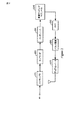
図2は、OFDMシステムで使用される送信機200の1つの実施形態を示す。送信機200は、スクランブラ210、エンコーダ220、インタリーバ230、変調マッピングモジュール240、逆高速フーリエ変換(IFFT)モジュール250、パルス整形モジュール260、及びアップコンバータ270を含む。送信機200は、データパケット、及び、このパケットが送信されるデータレートを受信する。この受信したパケットを、スクランブラ210がスクランブルし、エンコーダ220が符合化する。エンコーダ220は、従来型のエンコーダであるか、あるいは、誤り訂正符合化を可能にするその他幾つかの周知のエンコーダでありうる。
FIG. 2 shows one embodiment of a transmitter 200 used in an OFDM system. The transmitter 200 includes a
符号化されたビットは、ブロックへグループ化される。そして、各ブロックは、インタリーバ230によってインタリーブされ、変調マッピングモジュール240によって変調シンボルのシーケンスにマップされる。符号化され、インタリーブされた選択された長さのビットストリームは、変調に依存して、様々なビット数にグループ化される。一般に、このビットストリームは、1ビット、2ビット、4ビット、又は6ビットのうちの1つにグループ化され、バイフェースシフトキーイング(BPSK)変調、直交位相シフトキーイング(QPSK)変調、16直交振幅変調(QAM)、又は、64−QAMそれぞれにおける変調シンボルを表す複素数のシーケンスに変換される。BPSK、QPSK、及びQAMは、当該技術において周知の変調技術であり、詳細には説明しない。上述した変調フォーマットに加えて、あるいはその代わりに、他の変調フォーマットも利用されうることが注目されるべきである。
The encoded bits are grouped into blocks. Each block is then interleaved by
各OFDMシンボルはその後サブキャリアに割り当てられ、逆高速フーリエ変換される。これにより、単一のOFDMシンボルの時間ドメインサンプルが得られる。ここで、周期的なプレフィックスを各シンボルに加えることができる。パルス整形機能が送信機200によって提供されているのであれば、パルス整形モジュール260によってパルス整形が行われうる。そして、シンボルは、通信チャネルによって、送信のために、アップコンバータ270によってアップコンバートされる。ここで、プログラム可能なパルス整形が使用されてもよい。
Each OFDM symbol is then assigned to a subcarrier and inverse fast Fourier transformed. This gives a time domain sample of a single OFDM symbol. Here, a periodic prefix can be added to each symbol. If a pulse shaping function is provided by the transmitter 200, the
データパケットは、変調シンボルの他に他の情報を含みうる。例えば、ヘッダ、リーディング、及び/又はプレアンブルが、必要に応じて、スクランブル前にパケットに追加されうる。ヘッダ情報は、データレート、及び、パケット長さ情報を含みうる。ヘッダの内容は、一般に、スクランブルされない。 The data packet may include other information in addition to the modulation symbols. For example, headers, readings, and / or preambles can be added to the packet before scrambling, if necessary. The header information may include data rate and packet length information. The contents of the header are generally not scrambled.
チャネル応答の推定値を得るために、パイロット信号の送信が使用される。より多くのパイロット信号が使用されるほど、良好なチャネル応答の推定値が得られる。しかしながら、パイロット送信は、相当量のオーバヘッドを加える。従って、パイロット送信の使用は、オーバヘッド考慮とのバランスを検討する必要がある。更に、興味のある帯域全体を横切るパイロット送信は、システム内の全体的な雑音を増す。パイロットの使用が最小化される場合、チャネル応答はしばしば不正確になるか、及び/又は、信頼性が低下し、もって、満足できる性能を与えなくなる。 A pilot signal transmission is used to obtain an estimate of the channel response. As more pilot signals are used, a better estimate of the channel response is obtained. However, pilot transmission adds a significant amount of overhead. Therefore, the use of pilot transmission must be balanced with overhead considerations. Further, pilot transmission across the entire band of interest increases the overall noise in the system. If pilot usage is minimized, the channel response will often be inaccurate and / or unreliable and will not provide satisfactory performance.
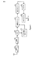
図3は、OFDMシステムで使用される受信機300の1つの実施形態を示す。受信機300は、無線周波数/中間周波数(RF/IF)フロントエンド310、同期モジュール380、高速フーリエ変換(FFT)モジュール320、復調モジュール330、逆インタリーバ340、デコーダ350、逆スクランブラ360、及び、チャネル推定モジュール370を備える。図2は、受信機の簡略ブロック図を示していることに注目されるべきである。より典型的な商用受信機は、1又は複数のRF/IFフロントエンド310、同期モジュール380、FFTモジュール320、復調モジュール330、逆インタリーバ340、デコーダ350、逆デスクランブラ360、及び、チャネル推定モジュール370を制御するためのプロセッサ(図示せず)及び記憶媒体(図示せず)のような追加要素を備えうる。
FIG. 3 shows one embodiment of a receiver 300 used in the OFDM system. The receiver 300 includes a radio frequency / intermediate frequency (RF / IF)
RF/IFフロントエンド310は通信チャネルを介してデータを受信する。そして、信号がFFTモジュール320へ入力され、時間ドメインから周波数ドメインに変換される。FFTは、必要に応じて、周期的プレフィックスを削除した後に行なわれる。チャネル推定モジュール370は、周波数ドメイン信号を受信し、チャネル推定値を提供する。また、周波数ドメイン信号は、受信信号を調節する際に位相誤り訂正を与える位相ロックループ(PLL)にも入力されうる。復調された信号は、逆インタリーバ340によって逆インタリーブされ、デコーダ350によって復号される。デコーダ350は、ビタビ(Viterbi)デコーダでありうる。そして、復号されたデータは、逆スクランブラ360によって逆スクランブルされ、オリジナルのデータ情報が復元される。信号フィールドが復号されている間、サンプルを保持するために、追加バッファも実装されうる。
The RF / IF
FFT処理後、各サブキャリアのチャネル推定を行なうために、プリアンブルが取得され、使用される。初期チャネル推定値は、パイロット信号に基づいて得ることができる。 After the FFT processing, a preamble is acquired and used to perform channel estimation for each subcarrier. An initial channel estimate can be obtained based on the pilot signal.
チャネル推定モジュール370は、周波数ドメイン信号のチャネル推定を行う。例えば、FFT処理の後、サブキャリアの信号は、以下のように、式[1]で表わすことができる。
Yn=HnXn+Nn [1]
しかしながら、他のアプローチ及び技術もまた利用されうる。
Y n = H n X n + N n [1]
However, other approaches and techniques can also be utilized.
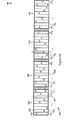
図4Aは、隣接するサブ帯域404、408、412、及び416へ分割された周波数帯域400の構成を例示する。一例として、図4Aは、4つの隣接するサブ帯域404、408、412、及び416を有する実施形態を図示している。設計制約又はその他の理由によって、任意数のサブ帯域が使用されてよい。サブ帯域の各々は、多くのサブキャリアを含む。サブキャリア420,422等であるそれらは、同じ数であるか、あるいは異なる数であるかもしれない。
FIG. 4A illustrates the configuration of frequency band 400 divided into
例えば、5MHzのシステムは、合計512のサブキャリアを持っているかもしれない。帯域幅全体が、4つの隣接するサブ帯域に分割されるのであれば、4つのサブ帯域404,408,412,及び416の各々は、それぞれ128のサブキャリアを有する1.25MHzに分割される。ある局面では、サブ帯域の各々は、2の累乗である数に分割され、個々のサブ帯域内のサブキャリアの数もまた2の累乗であるかもしれない。この特性は、個々のサブ帯域について高速フーリエ変換(FFT)及び逆高速フーリエ変換(IFFT)をとるのに役立つ。また、チャネル推定の目的にも役立つ。
For example, a 5 MHz system may have a total of 512 subcarriers. If the entire bandwidth is divided into four adjacent subbands, each of the four
帯域幅400の全体を、複数のサブ帯域に分割することによって、所定のサブ帯域内のサブキャリアが常に同じサブ帯域内でホップするようにホッピングパターンが制限される。従って、唯一のサブバンドに割り当てられたユーザは、その所定のサブ帯域にわたったチャネル推定値のみを決定する必要があり、そのサブ帯域のパイロットトーンのみを使用する。例えば、サブ帯域毎に異なるチャネルツリーが使用される場合、ユーザは、そのサブ帯域に割り当てられている限り、そのチャネルツリーに対しスケジュールされるかもしれない。 By dividing the entire bandwidth 400 into a plurality of subbands, the hopping pattern is limited so that subcarriers in a given subband always hop within the same subband. Thus, a user assigned to a single subband needs to determine only the channel estimate over that given subband and uses only the pilot tones for that subband. For example, if a different channel tree is used for each subband, the user may be scheduled for that channel tree as long as it is assigned to that subband.
上述したように、サブ帯域の各々は、複数のサブキャリアへ分割されうる。例えば、サブ帯域404は、サブキャリアC1,1、C1,2、…C1、N−1、及びC1,Nを含む。同様に、サブ帯域408,412,及び416は、複数のキャリアに分割される。 As described above, each subband may be divided into a plurality of subcarriers. For example, the subband 404 includes subcarriers C 1,1 , C 1,2 ,... C 1, N−1 , and C 1, N. Similarly, subbands 408, 412, and 416 are divided into a plurality of carriers.
チャネル推定は、一般的な広帯域パイロット信号の使用によって行なわれうる。トーンの一部は、パイロットシンボルのために確保される。図4Aは、これらパイロットシンボルを、文字「X」を用いて表す。これらパイロットシンボルは、一般に、システム設計に依存する最適な性能のために、帯域幅400の全体にわたって、例えば等間隔とされる。更に、ある場合には、パイロットは、ランダムパターン、準ランダムパターン、あるいはホッピングパターンによって送信されうる。 Channel estimation may be performed by using a general wideband pilot signal. Part of the tone is reserved for pilot symbols. FIG. 4A represents these pilot symbols using the letter “X”. These pilot symbols are typically equally spaced throughout the bandwidth 400 for optimum performance depending on the system design, for example. Further, in some cases, the pilot can be transmitted in a random pattern, a quasi-random pattern, or a hopping pattern.
ユーザが、与えられたサブ帯域のチャネルを推定する場合に生じうる問題は、サブ帯域の端部近くのサブ帯域キャリアにおいて、大きなチャネル推定誤差が生じうることである。この目的のために帯域の端部近くのサブキャリアのデータがわざとブランクに(blank out)される。他の局面では、ユーザが、近隣サブ帯域において、過剰にパイロットを使用できるのであれば、チャネル推定は、他のサブ帯域からのパイロットを使用することによって、与えられたサブ帯域の端部におけるサブキャリアにおいて改善されうる。この場合、ブランクキャリアは必要ではないかもしれない。 A problem that can occur when a user estimates a channel in a given subband is that a large channel estimation error can occur in a subband carrier near the edge of the subband. For this purpose, the data of the subcarriers near the edge of the band are intentionally blanked out. In other aspects, if the user is able to use excessive pilots in neighboring subbands, channel estimation can be performed by using pilots from other subbands, thereby reducing subbands at the end of a given subband. It can be improved in the carrier. In this case, a blank carrier may not be necessary.
例えば、誰かがサブキャリアC2,1のチャネルを推定しているのであれば、ユーザは、チャネル応答を推定であるために、サブ帯域408内のパイロット信号を使用するだろう。しかしながら、周波数においてはるかに離れたサブキャリアである次の所定のサブキャリアで受信されたパイロット信号を検討する場合、大きな誤差が含まれる。例えば、サブ帯域サブキャリアC2,Nにおけるパイロット信号は、サブキャリアC2,1から、周波数においてはるかに離れている。一方、サブキャリアC1,Nは、異なるサブ帯域(404)にあるが、サブキャリアC2,1に隣接している。同様に、サブ帯域C1,N−1は、2つ次のサブキャリアC2,1と周波数において比較的近い。この実施形態では、近隣のサブ帯域で受信されたパイロット信号が、周波数におけるある予め定めた差分のために使用されうる。この場合、線424は、サブキャリアC2,1がそのチャネル応答を推定する際に考慮する境界を表す。代替実施形態では、興味のあるこのサブ帯域内のパイロット信号でさえも、興味のあるサブキャリアから周波数において離れすぎていると考えられた場合には無視されうる。この実施形態では、線428の外側にあるサブキャリアは、サブキャリアC2,1のチャネル応答を決定する場合に考慮されない。
For example, if someone is estimating the channel of subcarrier C 2,1 , the user will use the pilot signal in
図4Bは、ハイブリッド隣接サブ帯域450を有する分割された周波数帯域幅の構造を図示する。この実施形態では、あるサブキャリアがグループ化され、隣接している。しかしながら、隣接するサブ帯域からなる小さなグループは、サブ帯域内のサブキャリアからなる他の小さなグループとは隣接していないかもしれない。例えば、C1サブ帯域は、グループ454,458,及び462によって表され、第2のサブ帯域は、サブキャリアグループ466,470、及び474によって表される。図4Aに記載したのと同じ方法で、与えられたサブキャリアに対するチャネル応答を推定することは、近隣のサブ帯域と同様に、サブ帯域のその部分で受信されたパイロット信号を用いて達成される。
FIG. 4B illustrates a divided frequency bandwidth structure with hybrid
ある局面では、ユーザとの送信をスケジュールすることによってホッピングが提供される。これによって、連続した送信期間、又は期間のグループが、例えば、サブ帯域を備えたサブキャリアのように、互いに異なるサブキャリアを使用できる。これらは、周知のパターン及びパターンジェネレータを用いることによって提供される。 In one aspect, hopping is provided by scheduling transmissions with users. Thereby, different transmission carriers can be used in continuous transmission periods or groups of periods, for example, subcarriers with subbands. These are provided by using known patterns and pattern generators.
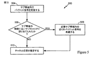
図5は、チャネル推定処理500を示す。ここでは、与えられたサブ帯域の外側で受信したパイロット信号が、チャネル推定処理において使用される。パイロット信号は、与えられたサブ帯域内で受信される(504)。興味のあるサブキャリアが、サブ帯域の端部近くにあるかが判定される。サブキャリアが「近い」と思われるものは、ネットワーク展開、チャネル条件、又はその他の要因に基づいて変わりうる。与えられたキャリアがサブ帯域の端部に近い場合、近隣のサブ帯域内で受信されたパイロット信号が利用される(508)。近隣のサブ帯域全体、あるいは、近隣のサブ帯域の予め定めた部分のパイロット信号が、チャネル応答を推定するために利用されうる(512)。割り当てられたサブキャリアが、サブ帯域の端部近くでないのであれば、近隣のパイロットは考慮される必要は無く、チャネル応答は、近隣のサブ帯域内のパイロット信号を用いることなく推定されうる(512)。一般に、ユーザのサブキャリアはサブ帯域全体にわたって分布しているので、サブ帯域全体に対するチャネル推定が使用される。従って、近隣のサブ帯域内のパイロットが、端部の近くのトーンのチャネルを推定するために使用される。サブ帯域内のパイロットは、他のすべてのトーンに使用される。
FIG. 5 shows a
例えば、アクティブセットベース制約(Active Set Based Restricted:ABSR)のような周波数再使用スキームは、その再使用セットとして、隣接するサブ帯域を使用しうる。ASBR技術は、2004年12月22日に出願され、"Feedback to Support Restrictive Reuse"と題された特許出願11/020,707号と、2004年12月22日に出願され、"Restrictive Reuse Set Management"と題された特許出願11/021,189号とにより詳細に記載されている。これらは本願と同じ譲受人に譲渡され、本明細書に参照によって明らかに組み込まれている。セル間干渉と格闘し、かつ信号対雑音比を改善するために、無線システムは、周波数再使用スキームを適用しうる。ここでは、システムにおいて利用可能なすべての周波数帯域が、各セル内で使用されるとは限らない。 For example, a frequency reuse scheme such as Active Set Based Restricted (ABS) may use adjacent subbands as its reuse set. ASBR technology was filed on Dec. 22, 2004, entitled “Feedback to Support Restrictive Reuse”, patent application 11 / 020,707, and filing on Dec. 22, 2004, “Restrictive Reuse Set Management. Is described in more detail in the patent application 11 / 021,189 entitled “. These are assigned to the same assignee as the present application and are expressly incorporated herein by reference. In order to combat inter-cell interference and improve the signal-to-noise ratio, the wireless system may apply a frequency reuse scheme. Here, not all frequency bands available in the system are used in each cell.
例えば、あるシステムは、7つのセル再使用パターン、及びK=7の再使用係数を適用しうる。このシステムについては、システム全体の帯域幅Wが、7つの等しい周波数帯域に分割される。また、7つのセルクラスタ内のセルはそれぞれ、7つの周波数帯域のうちの割り当てられた1つである。セルはそれぞれ、1つのみの周波数帯域を使用する。また、7番目のセル毎に同じ周波数帯域を再使用する。この周波数再使用スキームでは、同じ周波数帯域は、互いに隣接していないセル内のみで再使用される。そして、各セル内で観察されるセル間干渉は、全てのセルが同じ周波数帯域を使用する場合と比較して減少する。しかしながら、各セルは、システム帯域幅全体のうちの一部しか使用できないので、大きな再使用係数は、利用可能なシステムリソースの非効率的な使用を表わす。この同じ再使用スキームは、パイロット信号にも同様に適用されうる。このように、送信されたデータに関する信号対雑音比で見られる改善は、送信されたパイロットにおいても見られる。 For example, a system may apply 7 cell reuse patterns and a reuse factor of K = 7. For this system, the overall system bandwidth W is divided into seven equal frequency bands. Each cell in the seven cell clusters is an assigned one of the seven frequency bands. Each cell uses only one frequency band. The same frequency band is reused for every seventh cell. In this frequency reuse scheme, the same frequency band is reused only in cells that are not adjacent to each other. Then, the inter-cell interference observed in each cell is reduced compared to the case where all the cells use the same frequency band. However, since each cell can only use a portion of the overall system bandwidth, a large reuse factor represents an inefficient use of available system resources. This same reuse scheme can be applied to pilot signals as well. Thus, the improvement seen in the signal to noise ratio for the transmitted data is also seen in the transmitted pilot.
ユーザが、帯域幅のある部分を使用することに制限される場合、このユーザの帯域外出力は、実質的により低くなる。隣接ホッピングスキームは、この利益を得るために逆方向リンク上で使用することができる。同様に、更なる周波数ダイバーシティを得るために、ユーザは、与えられた任意の時間において単一のサブ帯域に割り当てられるが、このサブ帯域は時間にわたって変わりうる。 If a user is limited to using some portion of the bandwidth, the user's out-of-band power will be substantially lower. Adjacent hopping schemes can be used on the reverse link to gain this benefit. Similarly, to obtain additional frequency diversity, users are assigned to a single subband at any given time, but this subband can vary over time.
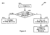
図6は、ユーザが、与えられたサブ帯域に割り当てられる処理600を示す。ユーザを、1より多いサブ帯域内で動作させることが望ましい状況がありうる。反対に、ユーザを、与えられたサブ帯域内のみで動作させることが望ましい状況がありうる。例えば、MIMOユーザは、多数の空間チャネルを推定する必要がある。従って、広帯域のパイロット信号が、推定された全ての空間チャネルに必要とされるだろう。4つのアンテナMIMO送信の場合、4つの広帯域パイロット信号を送信しなければならない。従って、MIMOユーザが、利用されている空間チャネルの全てについて変わりうるか、あるいは、同一でありうる特定のサブ帯域に割り当てられることが有用かもしれない。MIMOユーザの更なるチャネルを推定するために必要な追加のパイロットトーンが、与えられたサブ帯域内で割り当てられる必要がある。従って、帯域幅オーバヘッドが著しく低減される。
FIG. 6 shows a
別の例では、レイテンシに敏感なユーザが、周波数ダイバーシティを必要とする。従って、レイテンシに敏感なユーザは、多数のサブ帯域内のサブキャリアに割り当てられうる。個々のサブ帯域に対して、より少ない周波数ダイバーシティが利用可能であるので、マルチユーザダイバーシティゲインの能力が高められる。従って、レイテンシに敏感なユーザを、多数のサブ帯域内で動作させることは、周波数ダイバーシティを高め、マルチユーザダイバーシティゲインを下げる。 In another example, a latency sensitive user needs frequency diversity. Thus, latency sensitive users can be assigned to subcarriers in multiple subbands. Because less frequency diversity is available for individual subbands, the ability of multi-user diversity gain is enhanced. Thus, operating a latency sensitive user within multiple subbands increases frequency diversity and lowers multiuser diversity gain.
そのようなユーザが処理されうる処理を図6に示す。ユーザのニーズが識別される(604)。ユーザが、1より多いサブ帯域内にいる必要があるかが判定される(608)。ユーザを、1より多いサブ帯域内で動作させることが望ましいと判定された場合、ユーザは、多数のサブ帯域内の多数のサブキャリア内で動作するように割り当てられる(612)。この処理は、レイテンシに敏感なユーザのために生じうるものを代表する。一方、ユーザが、1つのサブ帯域のみで動作する必要があると判定された場合には、ユーザは、1つのサブ帯域内のサブキャリアに割り当てられる(616)。これは、MIMOユーザの例でありうる。従って、MIMOの場合、選択されたサブ帯域とともに、パイロット信号が割り当てられる(620)。 A process that can be processed by such a user is shown in FIG. User needs are identified (604). It is determined whether the user needs to be in more than one subband (608). If it is determined that it is desirable to operate the user in more than one subband, the user is assigned to operate in multiple subcarriers in multiple subbands (612). This process is representative of what can occur for latency sensitive users. On the other hand, if it is determined that the user needs to operate in only one subband, the user is assigned to a subcarrier in one subband (616). This can be an example of a MIMO user. Accordingly, for MIMO, a pilot signal is assigned (620) along with the selected subband.
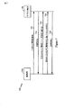
図7は、MIMOユーザを割り当てる処理700を示す。基地局704は、全帯域幅を介してパイロット信号を送る。それはモバイル端末708によって受信される。モバイル端末708は、パイロット信号を受信し、チャネル品質インジケータ(CQI)を決定する(712)。それは、基地局に送り戻される。条件及び希望に応じて、異なるCQIの表示が基地局に送られうる。
FIG. 7 shows a
CQIを計算し、送信するためのオプションは、各サブ帯域のためのCQIを基地局に送ることを含む。そして、基地局は、スケジューリング及びレート予測に関し、とりうる最良の決定を行うことができる。別のオプションは、最後に使用されたサブ帯域用のCQIを送信することである。又は、1つを越えるサブ帯域が使用された場合には、組み合わされたサブ帯域によってCQIを送る。この方法はオーバヘッドを減少させるが、基地局がユーザのサブ帯域を切り替えたい場合、レート予測アルゴリズム内の潜在的な不正確さと比較検討されねばならない。別のオプションは、ユーザの最良のサブ帯域用のCQIを送信することである。これは、サブ帯域インデクスの表示も必要とする。別のオプションは、ハンドセットが観察するものを、なしえる最良のサブ帯域として送信することである。更に、異なるサブ帯域用に多くのCQIが利用されうる。 Options for calculating and transmitting CQI include sending CQI for each subband to the base station. The base station can then make the best possible decisions regarding scheduling and rate prediction. Another option is to send the CQI for the last used subband. Or, if more than one subband is used, the CQI is sent by the combined subband. While this method reduces overhead, if the base station wants to switch user subbands, it must be compared with potential inaccuracies in the rate prediction algorithm. Another option is to send the CQI for the user's best subband. This also requires the display of the sub-band index. Another option is to transmit what the handset observes as the best sub-band that can be achieved. Moreover, many CQIs can be used for different subbands.
モバイル端末からCQIを受信すると、基地局704は、与えられたサブ帯域へユーザを割り当てる(716)。更に、基地局は、割り当てられたサブ帯域内で、追加のパイロット信号を送る(720)。そして、モバイル端末708は、選択されたサブ帯域内で、割り当てられた追加パイロット信号に対応するCQIを送る(724)。
Upon receiving the CQI from the mobile terminal, the
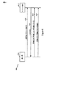
図8は、レイテンシに敏感なユーザを割り当てる処理800を示す。基地局804は、周波数帯域全体を介して、モバイル端末812に広帯域パイロット信号を送る(808)。CQIは、基地局804へ送り戻される(816)。そして、基地局804は、多数のサブ帯域内で動作するためのユーザを割り当てる(820)。これら多数のサブ帯域では、モバイル端末は、多数のサブ帯域で受信されたパイロット信号のCQIを決定し、興味のあるサブ帯域から基地局804へとCQIを送り戻す(824)。
FIG. 8 shows a
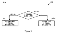
図9を参照して、スケジューリングのための構成を示す。このスケジューリング構成は、ユーザをスケジュールするためのサブ帯域数を決定する手段902を含む。これは、ユーザがMIMOユーザであるか否か、ユーザのレイテンシ、これらの組み合わせ、あるいはその他のアプローチに基づきうる。そして、ユーザを多数のサブ帯域にスケジュールする手段904、又は、ユーザを1つのサブ帯域にスケジュールする手段906が適切なものとして利用される。手段904及び手段906はまた、単一手段を備えうる。
With reference to FIG. 9, a configuration for scheduling is shown. This scheduling arrangement includes means 902 for determining the number of sub-bands for scheduling users. This may be based on whether the user is a MIMO user, the user's latency, a combination of these, or other approaches. Then, means 904 for scheduling the user in a number of sub-bands or means 906 for scheduling the user in one sub-band are used as appropriate.
図10には、チャネル推定のための構成1000が示される。この構成1000は、周波数帯域の1より多いサブ帯域内で、複数のパイロット信号が受信されたことを判定する手段1002と、1つのサブ帯域で受信された複数のパイロット信号のうちの幾つかに基づいて、その1つのサブ帯域のためのチャネル応答を推定する手段1004とを含む。更に、手段1004には、近隣のサブ帯域内で受信されたパイロット信号の少なくとも一部を使用して、与えられたサブ帯域におけるチャネル応答を推定する手段が含まれうる。
FIG. 10 shows a
本明細書で記載されたパイロット送信スキーム及びデータ送信スキームは、様々な手段によって実現されうる。例えば、これらの技術は、ハードウェア、ソフトウェア、あるいはそれらの組み合せで実現されうる。ハードウェア実装の場合、送信機ユニット及び受信機ユニットにおける処理を実行するために使用される要素は、1又は複数の特定用途向けIC(ASIC)、デジタル信号プロセッサ(DSP)、デジタル信号処理デバイス(DSPD)、プログラム可能論理回路(PLD)、フィールドプログラム可能なゲートアレイ(FPGA)、プロセッサ、コントローラ、マイクロコントローラ、マイクロプロセッサ、本明細書に記載の機能を実行するために設計されたその他の電子ユニット、又はこれらの組み合わせ内で実現されうる。 The pilot transmission scheme and data transmission scheme described herein may be implemented by various means. For example, these techniques can be realized in hardware, software, or a combination thereof. For hardware implementation, the elements used to perform processing in the transmitter unit and receiver unit are one or more application specific ICs (ASICs), digital signal processors (DSPs), digital signal processing devices ( DSPD), programmable logic circuit (PLD), field programmable gate array (FPGA), processor, controller, microcontroller, microprocessor, and other electronic units designed to perform the functions described herein , Or a combination thereof.
ソフトウェア実装の場合、本明細書に記載の送信スキームのため、送信機ユニット及び受信機ユニットにおける処理は、本明細書に記載の機能を実行するモジュール(例えば、手順、機能等)で実現されうる。ソフトウェアコードはメモリに格納され、プロセッサによって実行されうる。記憶ユニットは、プロセッサの内部又は外部に実装されうるが、何れの場合であれ、当該技術分野で周知の様々な手段を経由してプロセッサに通信可能に接続することができる。 For software implementations, because of the transmission scheme described herein, processing in the transmitter unit and receiver unit may be implemented with modules (eg, procedures, functions, etc.) that perform the functions described herein. . Software code may be stored in memory and executed by a processor. The storage unit may be implemented inside or outside the processor, but in any case can be communicatively connected to the processor via various means well known in the art.
開示した実施形態の前述した記載は、当業者が、本発明を実施又は利用することができるように提供される。これら実施形態に対する様々な変形は、当業者に容易に明らかになるであろう。また、本明細書で定めた一般的な原理は、本発明の精神又は範囲から逸脱することなく他の実施形態に適用されうる。従って、本発明は、本明細書に示した実施形態に限定されることは意図されておらず、本明細書に開示された原理及び斬新な特徴と一致する最も広いスコープが与えられるべきである。 The previous description of the disclosed embodiments is provided to enable any person skilled in the art to make or use the present invention. Various modifications to these embodiments will be readily apparent to those skilled in the art. In addition, the general principles defined herein may be applied to other embodiments without departing from the spirit or scope of the invention. Accordingly, the present invention is not intended to be limited to the embodiments shown herein, but is to be given the widest scope consistent with the principles and novel features disclosed herein. .
Claims (12)
ユーザのニーズを識別することと、
前記識別されたニーズにしたがって、前記ユーザへの送信が、単一のサブ帯域内が好ましいか、あるいは、1より多いサブ帯域内が好ましいかを判定することであって、各サブ帯域は、他の任意のサブ帯域に対してオーバラップしていないサブキャリアを含むことと、
前記判定に基づいて、前記送信を、前記単一のサブ帯域内で引き起こるように割り当てるか、あるいは、1より多いサブ帯域内で動作するように割り当てることと、
前記送信が前記単一のサブ帯域内で引き起こるように割り当てられた場合、前記単一のサブ帯域内に追加パイロット信号を割り当てることと
を備え、
前記判定することは更に、前記送信がMIMO送信であるかを判定し、
前記割り当てることは、前記送信がMIMO送信であると判定された場合には、前記送信を、前記単一のサブ帯域内で引き起こるように割り当て、
前記送信がMIMO送信であると判定され、かつ、前記単一のサブ帯域内に追加パイロット信号が割り当てられた場合、前記追加パイロット信号は、前記MIMO送信のために利用される、方法。 A resource allocation method for transmission in a wireless communication system operating within a given frequency band for a wireless device comprising:
Identifying user needs;
According to the identified needs, determining whether transmission to the user is preferred within a single sub-band or more than one sub-band, each sub-band being Including non-overlapping subcarriers for any subband of
Based on the determination, assigning the transmission to occur within the single subband, or assigning to operate within more than one subband ;
Allocating additional pilot signals within the single subband if the transmission is assigned to occur within the single subband ; and
The determining further determines whether the transmission is a MIMO transmission;
The assigning assigns the transmission to occur within the single subband if the transmission is determined to be a MIMO transmission;
The method, wherein if the transmission is determined to be a MIMO transmission and an additional pilot signal is assigned within the single subband, the additional pilot signal is utilized for the MIMO transmission .
を備える請求項1に記載の方法。 The method of claim 1, wherein the determining further comprises determining whether the transmission is a latency sensitive transmission.
前記識別されたニーズにしたがって、送信が、単一のサブ帯域内が好ましいか、あるいは、1より多いサブ帯域内が好ましいかを判定する手段と、
前記送信を、前記単一のサブ帯域内で引き起こるように割り当てるか、あるいは、1より多いサブ帯域内で動作するように割り当てる手段と、
前記送信が前記単一のサブ帯域内で引き起こるように割り当てられた場合、前記単一のサブ帯域内に追加パイロット信号を割り当てる手段と
を備え、
前記判定する手段は更に、前記送信がMIMO送信であるかを判定し、
前記割り当てる手段は、前記送信がMIMO送信であると判定された場合には、前記送信を、前記単一のサブ帯域内で引き起こるように割り当て、
前記送信がMIMO送信であると判定され、かつ、前記単一のサブ帯域内に追加パイロット信号が割り当てられた場合、前記追加パイロット信号は、前記MIMO送信のために利用される、装置。 A means of identifying user needs;
Means for determining whether transmission is preferred within a single sub-band or within more than one sub-band according to said identified needs;
Means for allocating the transmission to occur within the single sub-band, or to operate within more than one sub-band ;
Means for allocating additional pilot signals within the single subband if the transmission is assigned to occur within the single subband ;
The means for determining further determines whether the transmission is a MIMO transmission;
The means for allocating assigns the transmission to occur within the single subband if the transmission is determined to be a MIMO transmission;
The apparatus, wherein if the transmission is determined to be a MIMO transmission and an additional pilot signal is assigned within the single subband, the additional pilot signal is utilized for the MIMO transmission .
Applications Claiming Priority (2)
| Application Number | Priority Date | Filing Date | Title |
|---|---|---|---|
| US63849404P | 2004-12-22 | 2004-12-22 | |
| US60/638,494 | 2004-12-22 |
Related Parent Applications (1)
| Application Number | Title | Priority Date | Filing Date |
|---|---|---|---|
| JP2007548621A Division JP4620130B2 (en) | 2004-12-22 | 2005-12-22 | Constrained hopping in wireless communication systems |
Related Child Applications (1)
| Application Number | Title | Priority Date | Filing Date |
|---|---|---|---|
| JP2013038882A Division JP2013153469A (en) | 2004-12-22 | 2013-02-28 | Constrained hopping in wireless communication systems |
Publications (2)
| Publication Number | Publication Date |
|---|---|
| JP2011010334A JP2011010334A (en) | 2011-01-13 |
| JP5259657B2 true JP5259657B2 (en) | 2013-08-07 |
Family
ID=36123142
Family Applications (3)
| Application Number | Title | Priority Date | Filing Date |
|---|---|---|---|
| JP2007548621A Expired - Fee Related JP4620130B2 (en) | 2004-12-22 | 2005-12-22 | Constrained hopping in wireless communication systems |
| JP2010173703A Expired - Fee Related JP5259657B2 (en) | 2004-12-22 | 2010-08-02 | Constrained hopping in wireless communication systems |
| JP2013038882A Pending JP2013153469A (en) | 2004-12-22 | 2013-02-28 | Constrained hopping in wireless communication systems |
Family Applications Before (1)
| Application Number | Title | Priority Date | Filing Date |
|---|---|---|---|
| JP2007548621A Expired - Fee Related JP4620130B2 (en) | 2004-12-22 | 2005-12-22 | Constrained hopping in wireless communication systems |
Family Applications After (1)
| Application Number | Title | Priority Date | Filing Date |
|---|---|---|---|
| JP2013038882A Pending JP2013153469A (en) | 2004-12-22 | 2013-02-28 | Constrained hopping in wireless communication systems |
Country Status (14)
| Country | Link |
|---|---|
| US (2) | US8571132B2 (en) |
| EP (1) | EP1836818A1 (en) |
| JP (3) | JP4620130B2 (en) |
| KR (1) | KR100956042B1 (en) |
| CN (1) | CN101124795A (en) |
| AR (1) | AR052443A1 (en) |
| AU (1) | AU2005318997A1 (en) |
| BR (1) | BRPI0519541A2 (en) |
| CA (1) | CA2590629A1 (en) |
| IL (1) | IL183870A0 (en) |
| MX (1) | MX2007007743A (en) |
| RU (2) | RU2374775C2 (en) |
| TW (1) | TWI383604B (en) |
| WO (1) | WO2006069401A1 (en) |
Families Citing this family (46)
| Publication number | Priority date | Publication date | Assignee | Title |
|---|---|---|---|---|
| US8634432B2 (en) * | 2005-05-06 | 2014-01-21 | Samsung Electronics Co., Ltd. | System and method for subcarrier allocation in a multicarrier wireless network |
| US8594207B2 (en) * | 2005-10-31 | 2013-11-26 | Motorola Mobility Llc | Method and apparatus for providing channel quality feedback in an orthogonal frequency division multiplexing communication system |
| US8054894B2 (en) * | 2005-10-31 | 2011-11-08 | Motorola Mobility, Inc. | Method and apparatus for providing channel quality feedback in an orthogonal frequency division multiplexing communication system |
| EP1994650B1 (en) | 2006-02-28 | 2012-12-19 | Rotani Inc. | Methods and apparatus for overlapping mimo antenna physical sectors |
| JP4738240B2 (en) * | 2006-04-19 | 2011-08-03 | シャープ株式会社 | Communication frequency setting method for wireless communication |
| JP4907657B2 (en) * | 2006-06-26 | 2012-04-04 | パナソニック株式会社 | Wireless communication apparatus and CQI generation method |
| US8417248B2 (en) * | 2006-08-14 | 2013-04-09 | Texas Instruments Incorporated | Methods and apparatus to schedule uplink transmissions in wireless communication systems |
| US8098212B2 (en) * | 2006-08-15 | 2012-01-17 | Cisco Technology, Inc. | Method for antenna array partitioning |
| JP5329417B2 (en) | 2006-11-01 | 2013-10-30 | クゥアルコム・インコーポレイテッド | Sub-band dependent resource management |
| US8305999B2 (en) * | 2007-01-05 | 2012-11-06 | Ravi Palanki | Resource allocation and mapping in a wireless communication system |
| US8825065B2 (en) * | 2007-01-19 | 2014-09-02 | Wi-Lan, Inc. | Transmit power dependent reduced emissions from a wireless transceiver |
| US8290447B2 (en) * | 2007-01-19 | 2012-10-16 | Wi-Lan Inc. | Wireless transceiver with reduced transmit emissions |
| GB2446197A (en) | 2007-02-05 | 2008-08-06 | Nec Corp | Frequency-hopping method and mobile communication system |
| US8213483B2 (en) * | 2007-02-06 | 2012-07-03 | Qualcomm Incorporated | Hopping structures for broadband pilot signals |
| US8831116B2 (en) * | 2007-03-20 | 2014-09-09 | Motorola Mobility Llc | Method and apparatus for providing channel quality and precoding metric feedback in an orthogonal frequency division multiplexing communication system |
| WO2008118067A2 (en) * | 2007-03-26 | 2008-10-02 | Telefonaktiebolaget Lm Ericsson (Publ) | Preparation phase for switching between su-mimo and mu-mimo |
| KR101381475B1 (en) | 2007-04-13 | 2014-04-04 | 삼성전자주식회사 | A method for transitioning a radio resource control state of a user terminal to an idle state, a system for the same, and a terminal thereof |
| US8213943B2 (en) * | 2007-05-02 | 2012-07-03 | Qualcomm Incorporated | Constrained hopping of DL reference signals |
| KR101329854B1 (en) * | 2007-06-05 | 2013-11-14 | 엘지전자 주식회사 | Method for transmitting control information in multi antenna system |
| KR101481166B1 (en) | 2007-06-25 | 2015-01-28 | 엘지전자 주식회사 | Method of transmitting feedback data in a multi-antenna system |
| WO2009002087A1 (en) * | 2007-06-25 | 2008-12-31 | Lg Electronics Inc. | Method of transmitting feedback data in multiple antenna system |
| KR20100025586A (en) * | 2007-08-02 | 2010-03-09 | 후지쯔 가부시끼가이샤 | Pilot arrangement method in mobile radio communication system and transmitter/receiver adopting same |
| KR101478362B1 (en) | 2007-08-10 | 2015-01-28 | 엘지전자 주식회사 | Method of transmitting feedback data in a multi-antenna system |
| CN101409883A (en) * | 2007-10-12 | 2009-04-15 | Nxp股份有限公司 | Method and system for planning down link auxiliary reference signal in multi-carrier wideband system |
| CN101610101B (en) * | 2008-06-16 | 2013-02-27 | 中兴通讯股份有限公司 | Frequency hopping method for downlink special pilot frequencies |
| CN101610231B (en) * | 2008-06-18 | 2013-06-05 | 中兴通讯股份有限公司 | Method and device for realizing frequency hopping |
| US8095103B2 (en) * | 2008-08-01 | 2012-01-10 | Qualcomm Incorporated | Upconverter and downconverter with switched transconductance and LO masking |
| EP2334114B1 (en) * | 2008-09-22 | 2016-10-12 | Sharp Kabushiki Kaisha | Wireless communication system, base station device, mobile station device, and wireless communication method |
| KR101156618B1 (en) | 2008-11-21 | 2012-06-14 | 연세대학교 산학협력단 | Method for allocating resources for wireless network |
| KR101608784B1 (en) * | 2009-01-21 | 2016-04-20 | 엘지전자 주식회사 | Method for allocating resouce for multicast and/or broadcast service data in wireless communication system and an appratus therefor |
| US8718169B2 (en) | 2010-06-15 | 2014-05-06 | Qualcomm Incorporated | Using a field format on a communication device |
| WO2012034580A1 (en) * | 2010-09-13 | 2012-03-22 | Nokia Siemens Networks Oy | Reduced radio resource control connectivity |
| CN102064920A (en) * | 2010-12-31 | 2011-05-18 | 大唐移动通信设备有限公司 | Method and device for acquiring CQI (Channel Quality Indicator) information |
| GB2487782B (en) * | 2011-02-04 | 2015-05-20 | Sca Ipla Holdings Inc | Telecommunications method and system |
| FR2992506B1 (en) * | 2012-06-25 | 2014-06-20 | Sigfox Wireless | METHOD FOR AUTHENTICATING DATA PACKETS RECEIVED BY A STATION OF A DIGITAL TELECOMMUNICATIONS SYSTEM |
| CN108495319B (en) * | 2012-09-07 | 2022-07-01 | 索尼公司 | Wireless transmission resource management device and method |
| CN104113843B (en) * | 2013-04-18 | 2020-09-11 | 索尼公司 | Spectrum management system and method |
| US9590764B2 (en) | 2014-09-15 | 2017-03-07 | Texas Instruments Incorporated | LTE transmission mask adjustment to maximize performance and reduce interference |
| WO2017135882A1 (en) | 2016-02-05 | 2017-08-10 | Telefonaktiebolaget Lm Ericsson (Publ) | Radio resource allocation in a narrowband communication system |
| JP7109883B2 (en) * | 2017-02-24 | 2022-08-01 | 株式会社Nttドコモ | Radio base station and radio communication method |
| CN109274628B (en) * | 2017-07-17 | 2021-08-03 | 普天信息技术有限公司 | A method and device for sending uplink services in a multi-subband system |
| US11405924B2 (en) * | 2017-12-08 | 2022-08-02 | Mediatek Singapore Pte. Ltd. | Communication interference mitigation systems and methods |
| US10772074B2 (en) | 2018-02-16 | 2020-09-08 | At&T Intellectual Property I, L.P. | Facilitation of reporting sub-band channel quality indicators for 5G or other next generation network |
| RU2713378C1 (en) * | 2019-06-14 | 2020-02-05 | Акционерное общество "Концерн "Созвездие" | Method of estimating channel parameters in ofdm systems |
| US11849438B2 (en) * | 2021-06-21 | 2023-12-19 | Qualcomm Incorporated | Channel oriented tone reservation for multiple input multiple output communications |
| CN113630360B (en) * | 2021-08-10 | 2022-05-24 | 中国科学院计算技术研究所 | Frequency hopping method and device for wireless communication |
Family Cites Families (45)
| Publication number | Priority date | Publication date | Assignee | Title |
|---|---|---|---|---|
| SE9401319L (en) * | 1994-04-19 | 1995-10-20 | Ellemtel Utvecklings Ab | telecommunication systems |
| US6359923B1 (en) * | 1997-12-18 | 2002-03-19 | At&T Wireless Services, Inc. | Highly bandwidth efficient communications |
| US20020154705A1 (en) | 2000-03-22 | 2002-10-24 | Walton Jay R. | High efficiency high performance communications system employing multi-carrier modulation |
| EP1720277B1 (en) * | 2000-07-05 | 2017-09-27 | Sony Deutschland Gmbh | Pilot pattern design for multiple antennas in an OFDM system |
| CN100576901C (en) * | 2000-08-25 | 2009-12-30 | 索尼公司 | Digit broadcasting system |
| US6907270B1 (en) | 2000-10-23 | 2005-06-14 | Qualcomm Inc. | Method and apparatus for reduced rank channel estimation in a communications system |
| US6654408B1 (en) * | 2000-10-27 | 2003-11-25 | Wisconsin Alumni Research Foundation | Method and system for multi-carrier multiple access reception in the presence of imperfections |
| US6959050B2 (en) * | 2001-06-15 | 2005-10-25 | Motorola, Inc. | Method and apparatus for synchronizing an OFDM signal |
| JP2003110529A (en) | 2001-10-02 | 2003-04-11 | Sony Corp | Transmission device, communication system and communication method thereof |
| JP4245330B2 (en) | 2001-10-31 | 2009-03-25 | パナソニック株式会社 | Wireless transmission apparatus and wireless communication method |
| US7130592B2 (en) | 2001-10-31 | 2006-10-31 | Matsushita Electric Industrial Co., Ltd. | Radio transmission apparatus and radio communication method |
| US7020110B2 (en) | 2002-01-08 | 2006-03-28 | Qualcomm Incorporated | Resource allocation for MIMO-OFDM communication systems |
| JP3993441B2 (en) | 2002-02-01 | 2007-10-17 | 株式会社日立国際電気 | OFDM signal receiver |
| US7295626B2 (en) * | 2002-03-08 | 2007-11-13 | Alvarion Ltd. | Orthogonal division multiple access technique incorporating single carrier and OFDM signals |
| GB2386519B (en) | 2002-03-12 | 2004-05-26 | Toshiba Res Europ Ltd | Adaptive Multicarrier Communication |
| GB2386476B (en) * | 2002-03-14 | 2004-05-12 | Toshiba Res Europ Ltd | Antenna signal processing systems |
| US7173991B2 (en) * | 2002-06-17 | 2007-02-06 | Hitachi, Ltd. | Methods and apparatus for spectral filtering channel estimates |
| US7551546B2 (en) * | 2002-06-27 | 2009-06-23 | Nortel Networks Limited | Dual-mode shared OFDM methods/transmitters, receivers and systems |
| EP1392005A1 (en) | 2002-08-13 | 2004-02-25 | Siemens Aktiengesellschaft | Method for channel estimation and corresponding radio communications system |
| US8320301B2 (en) * | 2002-10-25 | 2012-11-27 | Qualcomm Incorporated | MIMO WLAN system |
| US7039001B2 (en) | 2002-10-29 | 2006-05-02 | Qualcomm, Incorporated | Channel estimation for OFDM communication systems |
| US6928062B2 (en) | 2002-10-29 | 2005-08-09 | Qualcomm, Incorporated | Uplink pilot and signaling transmission in wireless communication systems |
| JP4163937B2 (en) | 2002-12-06 | 2008-10-08 | 松下電器産業株式会社 | OFDM-CDMA transmitter and OFDM-CDMA transmission method |
| US20040120300A1 (en) * | 2002-12-02 | 2004-06-24 | Board Of Regents, The University Of Texas System | System, method and apparatus for parallel information transmission in wireless communication systems |
| KR100575980B1 (en) * | 2002-12-24 | 2006-05-02 | 삼성전자주식회사 | Apparatus and method for minimizing peak to average power ratio in a communication system using orthogonal frequency division multiplexing scheme |
| US7280467B2 (en) | 2003-01-07 | 2007-10-09 | Qualcomm Incorporated | Pilot transmission schemes for wireless multi-carrier communication systems |
| WO2004077777A1 (en) * | 2003-02-28 | 2004-09-10 | Nortel Networks Limited | Sub-carrier allocation for ofdm |
| JP2004304590A (en) | 2003-03-31 | 2004-10-28 | Sony Corp | OFDM demodulator and method |
| JP3838237B2 (en) | 2003-04-30 | 2006-10-25 | ソニー株式会社 | Wireless communication system, transmitting apparatus and receiving apparatus |
| US7286603B2 (en) * | 2003-05-01 | 2007-10-23 | Nokia Corporation | Method and apparatus for increasing data rates in a wideband MC-CDMA telecommunication system |
| US7177297B2 (en) | 2003-05-12 | 2007-02-13 | Qualcomm Incorporated | Fast frequency hopping with a code division multiplexed pilot in an OFDMA system |
| KR100640461B1 (en) * | 2003-07-30 | 2006-10-30 | 삼성전자주식회사 | Apparatus and method for subchannel allocation in mobile communication system using orthogonal frequency division multiple access |
| US6985535B2 (en) * | 2003-10-31 | 2006-01-10 | Motorola, Inc. | Channel condition estimation for pilot coefficient selection |
| JP4314099B2 (en) | 2003-11-19 | 2009-08-12 | パナソニック株式会社 | OFDM receiver |
| US7489621B2 (en) * | 2003-12-30 | 2009-02-10 | Alexander A Maltsev | Adaptive puncturing technique for multicarrier systems |
| WO2005089125A2 (en) * | 2004-03-05 | 2005-09-29 | Interdigital Technology Corporation | Full duplex communication system using disjoint spectral blocks |
| KR100620914B1 (en) | 2004-04-07 | 2006-09-13 | 삼성전자주식회사 | Apparatus and method for switching between MC mode and diversity mode in broadband wireless communication system |
| US7047006B2 (en) * | 2004-04-28 | 2006-05-16 | Motorola, Inc. | Method and apparatus for transmission and reception of narrowband signals within a wideband communication system |
| US7257406B2 (en) | 2004-07-23 | 2007-08-14 | Qualcomm, Incorporated | Restrictive reuse set management |
| KR100929103B1 (en) * | 2004-08-17 | 2009-11-30 | 삼성전자주식회사 | Frequency allocating apparatus and method for supporting high speed forward packet data service in orthogonal frequency multiplexing mobile communication system |
| US20060045192A1 (en) * | 2004-08-25 | 2006-03-02 | Hiroshi Hayashi | Method and apparatus for pilot channel transmission and reception within a multi-carrier communication system |
| US7672383B2 (en) | 2004-09-17 | 2010-03-02 | Qualcomm Incorporated | Noise variance estimation in wireless communications for diversity combining and log-likelihood scaling |
| JP2006101019A (en) | 2004-09-28 | 2006-04-13 | Matsushita Electric Ind Co Ltd | OFDM receiving apparatus and OFDM relay apparatus |
| JP4516489B2 (en) | 2004-10-12 | 2010-08-04 | 日本放送協会 | Receiver |
| US7548752B2 (en) | 2004-12-22 | 2009-06-16 | Qualcomm Incorporated | Feedback to support restrictive reuse |
-
2005
- 2005-12-21 US US11/315,744 patent/US8571132B2/en not_active Expired - Fee Related
- 2005-12-22 AR ARP050105520A patent/AR052443A1/en unknown
- 2005-12-22 JP JP2007548621A patent/JP4620130B2/en not_active Expired - Fee Related
- 2005-12-22 KR KR1020077016202A patent/KR100956042B1/en not_active Expired - Fee Related
- 2005-12-22 CN CNA2005800485533A patent/CN101124795A/en active Pending
- 2005-12-22 EP EP05856110A patent/EP1836818A1/en not_active Withdrawn
- 2005-12-22 AU AU2005318997A patent/AU2005318997A1/en not_active Abandoned
- 2005-12-22 TW TW094146433A patent/TWI383604B/en not_active IP Right Cessation
- 2005-12-22 MX MX2007007743A patent/MX2007007743A/en active IP Right Grant
- 2005-12-22 WO PCT/US2005/047647 patent/WO2006069401A1/en not_active Ceased
- 2005-12-22 RU RU2007127882/09A patent/RU2374775C2/en not_active IP Right Cessation
- 2005-12-22 BR BRPI0519541-1A patent/BRPI0519541A2/en not_active IP Right Cessation
- 2005-12-22 CA CA002590629A patent/CA2590629A1/en not_active Abandoned
-
2007
- 2007-06-12 IL IL183870A patent/IL183870A0/en unknown
-
2009
- 2009-09-02 RU RU2009133038/09A patent/RU2009133038A/en not_active Application Discontinuation
-
2010
- 2010-08-02 JP JP2010173703A patent/JP5259657B2/en not_active Expired - Fee Related
-
2013
- 2013-02-28 JP JP2013038882A patent/JP2013153469A/en active Pending
- 2013-10-28 US US14/064,482 patent/US20140050249A1/en not_active Abandoned
Also Published As
| Publication number | Publication date |
|---|---|
| KR100956042B1 (en) | 2010-05-06 |
| BRPI0519541A2 (en) | 2009-02-17 |
| US8571132B2 (en) | 2013-10-29 |
| US20060146760A1 (en) | 2006-07-06 |
| CN101124795A (en) | 2008-02-13 |
| JP2013153469A (en) | 2013-08-08 |
| IL183870A0 (en) | 2007-10-31 |
| JP2008526141A (en) | 2008-07-17 |
| RU2007127882A (en) | 2009-01-27 |
| RU2009133038A (en) | 2011-03-10 |
| TW200640174A (en) | 2006-11-16 |
| AR052443A1 (en) | 2007-03-21 |
| TWI383604B (en) | 2013-01-21 |
| AU2005318997A1 (en) | 2006-06-29 |
| EP1836818A1 (en) | 2007-09-26 |
| MX2007007743A (en) | 2007-08-21 |
| WO2006069401A1 (en) | 2006-06-29 |
| JP2011010334A (en) | 2011-01-13 |
| US20140050249A1 (en) | 2014-02-20 |
| RU2374775C2 (en) | 2009-11-27 |
| KR20070087097A (en) | 2007-08-27 |
| CA2590629A1 (en) | 2006-06-29 |
| JP4620130B2 (en) | 2011-01-26 |
Similar Documents
| Publication | Publication Date | Title |
|---|---|---|
| JP5259657B2 (en) | Constrained hopping in wireless communication systems | |
| KR100571806B1 (en) | A method for reducing channel state information fed back from an adaptive OPM system and an adaptive OMD system using the same | |
| CN101548517B (en) | Wireless communication method and apparatus for allocating training signals and information bits | |
| USRE46774E1 (en) | Receiving a pilot design and channel estimation | |
| JP5062852B2 (en) | Pilot signal transmission method | |
| JP4046712B2 (en) | Subcarrier allocation apparatus and method in orthogonal frequency division multiplexing system | |
| US7526035B2 (en) | Apparatus and method for switching between an AMC mode and a diversity mode in a broadband wireless communication system | |
| CN1674572B (en) | Apparatus and method for subcarrier allocation in OFDM communication system | |
| KR20050014695A (en) | Apparatus and method for assigning sub channel in a communication system using orthogonal frequency division multiple access scheme | |
| KR101139170B1 (en) | Method and apparatus for transmitting/receiving packet data control channel in wireless communication system using ofdma | |
| JP2008541548A (en) | Configuration and operation method of channel in wireless communication system using adaptive modulation channel, diversity channel and diversity channel, transmission / reception apparatus and system for the same | |
| CN101064701B (en) | Method for transmitting measurement pilot and its user terminal, system | |
| KR100456477B1 (en) | System for channel information determining of OFDM and method thereof, its program stored recording medium | |
| JP4689682B2 (en) | Signal transmission / reception apparatus and method for high-speed frequency hopping-orthogonal frequency division communication system | |
| HK1112346A (en) | Constrained hopping in wireless communication systems | |
| HK1137594A (en) | Joint use of multi-carrier and single-carrier multiplexing schemes for wireless communication |
Legal Events
| Date | Code | Title | Description |
|---|---|---|---|
| A131 | Notification of reasons for refusal |
Free format text: JAPANESE INTERMEDIATE CODE: A131 Effective date: 20120605 |
|
| A601 | Written request for extension of time |
Free format text: JAPANESE INTERMEDIATE CODE: A601 Effective date: 20120905 |
|
| A602 | Written permission of extension of time |
Free format text: JAPANESE INTERMEDIATE CODE: A602 Effective date: 20120910 |
|
| A521 | Request for written amendment filed |
Free format text: JAPANESE INTERMEDIATE CODE: A523 Effective date: 20121011 |
|
| A02 | Decision of refusal |
Free format text: JAPANESE INTERMEDIATE CODE: A02 Effective date: 20121030 |
|
| A521 | Request for written amendment filed |
Free format text: JAPANESE INTERMEDIATE CODE: A523 Effective date: 20130228 |
|
| A911 | Transfer to examiner for re-examination before appeal (zenchi) |
Free format text: JAPANESE INTERMEDIATE CODE: A911 Effective date: 20130308 |
|
| TRDD | Decision of grant or rejection written | ||
| A01 | Written decision to grant a patent or to grant a registration (utility model) |
Free format text: JAPANESE INTERMEDIATE CODE: A01 Effective date: 20130326 |
|
| A61 | First payment of annual fees (during grant procedure) |
Free format text: JAPANESE INTERMEDIATE CODE: A61 Effective date: 20130424 |
|
| FPAY | Renewal fee payment (event date is renewal date of database) |
Free format text: PAYMENT UNTIL: 20160502 Year of fee payment: 3 |
|
| R150 | Certificate of patent or registration of utility model |
Free format text: JAPANESE INTERMEDIATE CODE: R150 |
|
| R250 | Receipt of annual fees |
Free format text: JAPANESE INTERMEDIATE CODE: R250 |
|
| LAPS | Cancellation because of no payment of annual fees |