JP5113239B2 - Methods and configurations for communication networks - Google Patents
Methods and configurations for communication networks Download PDFInfo
- Publication number
- JP5113239B2 JP5113239B2 JP2010500872A JP2010500872A JP5113239B2 JP 5113239 B2 JP5113239 B2 JP 5113239B2 JP 2010500872 A JP2010500872 A JP 2010500872A JP 2010500872 A JP2010500872 A JP 2010500872A JP 5113239 B2 JP5113239 B2 JP 5113239B2
- Authority
- JP
- Japan
- Prior art keywords
- mimo
- mode
- user
- modes
- preparation phase
- Prior art date
- Legal status (The legal status is an assumption and is not a legal conclusion. Google has not performed a legal analysis and makes no representation as to the accuracy of the status listed.)
- Expired - Fee Related
Links
Images


Classifications
-
- H—ELECTRICITY
- H04—ELECTRIC COMMUNICATION TECHNIQUE
- H04B—TRANSMISSION
- H04B7/00—Radio transmission systems, i.e. using radiation field
- H04B7/02—Diversity systems; Multi-antenna system, i.e. transmission or reception using multiple antennas
- H04B7/04—Diversity systems; Multi-antenna system, i.e. transmission or reception using multiple antennas using two or more spaced independent antennas
- H04B7/0413—MIMO systems
- H04B7/0452—Multi-user MIMO systems
-
- H—ELECTRICITY
- H04—ELECTRIC COMMUNICATION TECHNIQUE
- H04B—TRANSMISSION
- H04B7/00—Radio transmission systems, i.e. using radiation field
- H04B7/02—Diversity systems; Multi-antenna system, i.e. transmission or reception using multiple antennas
- H04B7/04—Diversity systems; Multi-antenna system, i.e. transmission or reception using multiple antennas using two or more spaced independent antennas
- H04B7/0413—MIMO systems
- H04B7/0417—Feedback systems
-
- H—ELECTRICITY
- H04—ELECTRIC COMMUNICATION TECHNIQUE
- H04B—TRANSMISSION
- H04B7/00—Radio transmission systems, i.e. using radiation field
- H04B7/02—Diversity systems; Multi-antenna system, i.e. transmission or reception using multiple antennas
- H04B7/04—Diversity systems; Multi-antenna system, i.e. transmission or reception using multiple antennas using two or more spaced independent antennas
- H04B7/06—Diversity systems; Multi-antenna system, i.e. transmission or reception using multiple antennas using two or more spaced independent antennas at the transmitting station
- H04B7/0613—Diversity systems; Multi-antenna system, i.e. transmission or reception using multiple antennas using two or more spaced independent antennas at the transmitting station using simultaneous transmission
- H04B7/0615—Diversity systems; Multi-antenna system, i.e. transmission or reception using multiple antennas using two or more spaced independent antennas at the transmitting station using simultaneous transmission of weighted versions of same signal
- H04B7/0619—Diversity systems; Multi-antenna system, i.e. transmission or reception using multiple antennas using two or more spaced independent antennas at the transmitting station using simultaneous transmission of weighted versions of same signal using feedback from receiving side
- H04B7/0621—Feedback content
- H04B7/0634—Antenna weights or vector/matrix coefficients
-
- H—ELECTRICITY
- H04—ELECTRIC COMMUNICATION TECHNIQUE
- H04B—TRANSMISSION
- H04B7/00—Radio transmission systems, i.e. using radiation field
- H04B7/02—Diversity systems; Multi-antenna system, i.e. transmission or reception using multiple antennas
- H04B7/04—Diversity systems; Multi-antenna system, i.e. transmission or reception using multiple antennas using two or more spaced independent antennas
- H04B7/06—Diversity systems; Multi-antenna system, i.e. transmission or reception using multiple antennas using two or more spaced independent antennas at the transmitting station
- H04B7/0613—Diversity systems; Multi-antenna system, i.e. transmission or reception using multiple antennas using two or more spaced independent antennas at the transmitting station using simultaneous transmission
- H04B7/0615—Diversity systems; Multi-antenna system, i.e. transmission or reception using multiple antennas using two or more spaced independent antennas at the transmitting station using simultaneous transmission of weighted versions of same signal
- H04B7/0619—Diversity systems; Multi-antenna system, i.e. transmission or reception using multiple antennas using two or more spaced independent antennas at the transmitting station using simultaneous transmission of weighted versions of same signal using feedback from receiving side
- H04B7/0636—Feedback format
- H04B7/0639—Using selective indices, e.g. of a codebook, e.g. pre-distortion matrix index [PMI] or for beam selection
-
- H—ELECTRICITY
- H04—ELECTRIC COMMUNICATION TECHNIQUE
- H04B—TRANSMISSION
- H04B7/00—Radio transmission systems, i.e. using radiation field
- H04B7/02—Diversity systems; Multi-antenna system, i.e. transmission or reception using multiple antennas
- H04B7/04—Diversity systems; Multi-antenna system, i.e. transmission or reception using multiple antennas using two or more spaced independent antennas
- H04B7/06—Diversity systems; Multi-antenna system, i.e. transmission or reception using multiple antennas using two or more spaced independent antennas at the transmitting station
- H04B7/0613—Diversity systems; Multi-antenna system, i.e. transmission or reception using multiple antennas using two or more spaced independent antennas at the transmitting station using simultaneous transmission
- H04B7/0615—Diversity systems; Multi-antenna system, i.e. transmission or reception using multiple antennas using two or more spaced independent antennas at the transmitting station using simultaneous transmission of weighted versions of same signal
- H04B7/0619—Diversity systems; Multi-antenna system, i.e. transmission or reception using multiple antennas using two or more spaced independent antennas at the transmitting station using simultaneous transmission of weighted versions of same signal using feedback from receiving side
- H04B7/0652—Feedback error handling
- H04B7/0654—Feedback error handling at the receiver, e.g. antenna verification at mobile station
-
- H—ELECTRICITY
- H04—ELECTRIC COMMUNICATION TECHNIQUE
- H04B—TRANSMISSION
- H04B7/00—Radio transmission systems, i.e. using radiation field
- H04B7/02—Diversity systems; Multi-antenna system, i.e. transmission or reception using multiple antennas
- H04B7/04—Diversity systems; Multi-antenna system, i.e. transmission or reception using multiple antennas using two or more spaced independent antennas
- H04B7/06—Diversity systems; Multi-antenna system, i.e. transmission or reception using multiple antennas using two or more spaced independent antennas at the transmitting station
- H04B7/0686—Hybrid systems, i.e. switching and simultaneous transmission
- H04B7/0689—Hybrid systems, i.e. switching and simultaneous transmission using different transmission schemes, at least one of them being a diversity transmission scheme
Landscapes
- Engineering & Computer Science (AREA)
- Computer Networks & Wireless Communication (AREA)
- Signal Processing (AREA)
- Physics & Mathematics (AREA)
- Mathematical Physics (AREA)
- Mobile Radio Communication Systems (AREA)
- Radio Transmission System (AREA)
Description
本発明は、通信ネットワークにおいて異なる送信モードを切替えるための方法および構成に関し、上記ネットワークは複数の送信アンテナおよび複数の受信アンテナを備え、上記モードはシングルユーザモードおよびマルチユーザモードを含む。 The present invention relates to a method and arrangement for switching between different transmission modes in a communication network, the network comprising a plurality of transmitting antennas and a plurality of receiving antennas, the modes comprising a single user mode and a multiuser mode.
E−UTRAN(Evoluted UTRAN)は、シングルユーザ(SU)およびマルチユーザ(MU)MIMO技術をサポートするので、上記モード間の切換えをサポートする必要がある。 Since E-UTRAN (Evolved UTRAN) supports single user (SU) and multi-user (MU) MIMO technologies, it is necessary to support switching between the above modes.
シングルユーザ(SU−)MIMOの送信スキームにおいては、全てのMIMOストリームが同時に1のユーザに割当てられ、このユーザによる非常に高いピークのデータレートの実現を可能とする。このアプローチは、基地局がユーザへ送信される十分な量のトラフィックデータをバッファしており、全てのMIMOストリームが十分に良好なチャネル品質を示す場合に実行できる。一般的には、シングルユーザMIMOは、分散の少ないチャネル環境において高いゲインを提供する。 In a single-user (SU-) MIMO transmission scheme, all MIMO streams are assigned to one user at the same time, allowing a very high peak data rate to be achieved by this user. This approach can be performed if the base station is buffering a sufficient amount of traffic data to be transmitted to the user and all MIMO streams exhibit a sufficiently good channel quality. In general, single user MIMO provides high gain in a less distributed channel environment.
マルチユーザ(MU−)MIMOの送信スキームにおいては、異なるMIMOストリーム上で同一のリソースブロックが数ユーザに同時に割当てられる。このスキームは、システムに同期して動作する多くのユーザが存在し、各ユーザが高いピークのデータレートを要求しない場合に効果的である。自明なソリューションは、これらの動作中のユーザの間でダウンリンクリソースを共有することである。 In a multi-user (MU-) MIMO transmission scheme, the same resource block is allocated to several users simultaneously on different MIMO streams. This scheme is effective when there are many users operating in sync with the system and each user does not require a high peak data rate. A trivial solution is to share downlink resources between these active users.
セルサーチおよびセル取得、セル識別、ユーザ装置測定、およびチャネル推定のためにリファレンス信号またはパイロット信号が利用される。リファレンス信号には、共通レファレンス信号(Common reference signal)と個別リファレンス信号(Dedicated reference signal)の2種類が存在する。 Reference or pilot signals are used for cell search and cell acquisition, cell identification, user equipment measurement, and channel estimation. There are two types of reference signals: a common reference signal (Common reference signal) and an individual reference signal (Dedicated reference signal).
FDDに基づくE−UTRANシステムにおいては、ユーザ装置が、シングルユーザMIMO(SU−MIMO)またはマルチユーザMIMO(MU−MIMO)モードのいずれであっても、同一の共通リファレンス信号を全ての状況において利用することが想定される。ユーザ装置は、上記共通リファレンス信号の測定に基づき、プリコーディングアンテナ重み(プリコーディング行列)を決定し、好敵なコードブックをフィードバック情報として基地局に供給する。しかし、共通リファレンス信号のみを利用することは、例えば、共通リファレンス信号を多様な状況(高分散、見通し有り(LoS)チャネル)に最適化することはできない、また、作成されたコードブックが全ての状況および全ての利用可能アンテナのソリューションを満たすためにフィードバックコードブック情報が(ビット数の観点から)比較的大きくなるなどの不都合を生じ得る。 In an E-UTRAN system based on FDD, the same common reference signal is used in all situations regardless of whether the user equipment is in a single user MIMO (SU-MIMO) mode or a multiuser MIMO (MU-MIMO) mode. It is assumed that The user apparatus determines a precoding antenna weight (precoding matrix) based on the measurement of the common reference signal, and supplies a favorable codebook to the base station as feedback information. However, using only the common reference signal, for example, cannot optimize the common reference signal in various situations (highly distributed, line-of-sight (LoS) channel), There may be inconveniences such as the feedback codebook information becomes relatively large (in terms of the number of bits) to meet the situation and all available antenna solutions.
共通リファレンス信号に加え、チャネル推定、および重み確認などを改善するために個別リファレンス信号を使用することができる。例えば、IEEE802.16の仕様書においては、個別リファレンス信号は任意的な特徴として規定されており、ユーザ装置がプリコーディング/ビームフォーミング行列を有さないので、利用される重みでなくプリコーディングパイロット信号をダウンリンク制御チャネルにおいて送信される場合に、オープンループプリコーディングまたはクローズドループ送信の利用をサポートできる。このため、ユーザ装置はこれらの個別パイロットシンボルを重みが正しくシステムに適用されるかを確認するために利用することができる。なお、個別パイロットは厳密にユーザ特有であってもよいし、同一の個別パイロットの組がユーザグループに割当てられていてもよい。後者のアプローチは、自明であるが、オーバーヘッドが少ない。個別パイロットの詳細な構成は本発明の範囲外であるが、例えばUS2007/0025460、およびUS2006/0109922のように、個別パイロットを構成するための多様な方法が存在する。一般的に個別チャネルによるいくつかの利益が存在する。例えば、個別チャネルを多様な状況(高分散、Losチャネルなど)に最適化して構成し、チャネル推定を改善し、セルオリエンテーション推定の向上を実現することができる。もう一つの重要な利点は、あらゆる可能性のある状況を含む大きなコードブックを利用するのでなく、考慮中の状況のために状況特有のコードブックを選択できるので、フィードバックコードブックシグナリングのオーバーヘッド(抑制されたビット数)を抑制できることである。 In addition to common reference signals, individual reference signals can be used to improve channel estimation, weight confirmation, and the like. For example, in the IEEE 802.16 specification, the individual reference signal is defined as an optional feature, and since the user equipment does not have a precoding / beamforming matrix, the precoding pilot signal is used instead of the weight used. Can be used in the downlink control channel to support the use of open-loop precoding or closed-loop transmission. For this reason, the user equipment can use these individual pilot symbols in order to confirm whether the weight is correctly applied to the system. The individual pilots may be strictly user-specific, or the same individual pilot set may be assigned to the user group. The latter approach is self-evident, but has less overhead. The detailed configuration of the individual pilots is outside the scope of the present invention, but there are various ways to configure the individual pilots, such as US2007 / 0025460 and US2006 / 0109922. There are generally some benefits from individual channels. For example, an individual channel can be optimized and configured for various situations (high dispersion, Los channel, etc.), channel estimation can be improved, and cell orientation estimation can be improved. Another important advantage is that you can choose a situation-specific codebook for the situation you are considering rather than using a large codebook that contains all possible situations, thus reducing the overhead of feedback codebook signaling (suppression) The number of bits generated).
このようなMIMO処理のための個別リファレンス信号のコンセプトは、TDDに基づくE−UTRANシステムにも適用することができる。 The concept of the individual reference signal for the MIMO processing can be applied to an E-UTRAN system based on TDD.
セル内でSU−MIMOまたはMU−MIMOが同時に利用される。2のスキーム間の切り替えは、各状況においてSU−およびMU−のゲインによる十分な利益を受けることが望まれる。上記切り替えは、ユーザトラフィック量、無線状況、ユーザによる通信品質要求に基づいてもよい。 In the cell, SU-MIMO or MU-MIMO is simultaneously used. Switching between the two schemes is desired to benefit fully from the SU- and MU- gains in each situation. The switching may be based on a user traffic amount, a radio situation, and a communication quality request by a user.
主に共通リファレンス信号に基づく現在のE−UTRANシステムにおいては、上記切り替えは半動的、または動的に行われる。双方の場合で、セル内のユーザ装置は適切なシグナリングにより知らされる。全てのユーザは同時に2つの方法を利用することになるので、切替関連情報をセル内の全てのユーザにブロードキャストすることがよりリソース効率が高い。また、シグナリングのオーバーヘッドを無く、切り替えが迅速であるという利点を伴うMIMOスキーム間の突然の切換えを行うことも可能であるが、ユーザ装置はどのスキームがスケジュールされているかを把握できない。SU−MIMOとMU−MIMOの切換えまたはその逆は、双方のスキームの利点を活用するために利用されるよく知られた技術である。しかし、TDDに基づくE−UTRANにおける前提は、同一の共通リファレンス信号がSU−MIMOおよびMU−MIMOの各々に利用されることである。これは、シンプルな構成であるが、チャネルの見通しやセルオリエンテーション推定から最適なアプローチではない。一方、個別リファレンス信号は、TDDに基づくE−UTRANに適するであろう。 In the current E-UTRAN system mainly based on a common reference signal, the switching is performed semi-dynamically or dynamically. In both cases, the user equipment in the cell is informed by appropriate signaling. Since all users will use two methods at the same time, it is more resource efficient to broadcast the switching related information to all users in the cell. It is also possible to switch suddenly between MIMO schemes with the advantage of fast switching without signaling overhead, but the user equipment cannot know which scheme is scheduled. Switching between SU-MIMO and MU-MIMO or vice versa is a well-known technique used to exploit the advantages of both schemes. However, the premise in E-UTRAN based on TDD is that the same common reference signal is used for each of SU-MIMO and MU-MIMO. Although this is a simple configuration, it is not an optimal approach from channel perspectives or cell orientation estimation. On the other hand, the individual reference signal would be suitable for E-UTRAN based on TDD.
SU−MIMOおよびMU−MIMOは、一般的にチャネル環境やトラフィック負荷などの異なるシナリオに最も適する。このため、異なるシナリオにおけるSU−MIMOおよびMU−MIMOに最適なパイロットは異なる。また、パイロットは好ましくは実際に利用されるスキームに関連づけられるべきである、すなわち、SU−MIMOおよびMU−MIMOに固有であるべきである。換言すると、個別またはMIMOモード固有パイロットは、最適なパフォーマンスを実現するため、および特定のMIMOスキームの利益を存分に活用するために必要である。 SU-MIMO and MU-MIMO are generally most suitable for different scenarios such as channel environment and traffic load. For this reason, the optimal pilots for SU-MIMO and MU-MIMO in different scenarios are different. Also, the pilot should preferably be associated with the scheme actually used, i.e., unique to SU-MIMO and MU-MIMO. In other words, individual or MIMO mode specific pilots are necessary to achieve optimal performance and to fully exploit the benefits of a particular MIMO scheme.
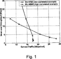
例えば、異なる環境においては異なるスキームが適する。図1に示したように、SIC(Successive Interference Cancellation)を伴うPARC(Per Antenna Rate Control)は、低相関状況におけるSU−MIMOのためのアンテナソリューションとして利用される。一方、直交ビーム選択を伴うDFT(Discrete Fourier Transform)に基づくビームフォーミングは、高相関状況におけるMU−MIMOのために利用される。DFTに基づくビームフォーミングソリューションによれば、アンテナ重みはDFTに基づく行列により得られ、同一のリソースブロックにおいて異なるユーザに信号を伝送するために直交重みが選択される。SU−MIMOおよびMU−MIMOの間の切り替えは、時間とともに例えばユーザ装置の位置の変化により相関が変化した場合にシステムを最適化するために有効である。同様に、半波長送信アンテナを利用する屋内および屋外環境は、ビームフォーミングの利用が屋外環境で有効であるが、屋内環境で有効でないという異なるバラバラな状態を示す。DFTに基づくパイロットは屋外の高相関MU−MIMO状況で利用される一方、分散的FDMパイロットは屋内の低相関SU−MIMO状況で利用される。特定のシナリオにおける所定のスキームに関してはただ一つの個別パイロットの組を有すれば十分かもしれないが、例えばシステム負荷における変化により状況が変わった場合、他の個別パイロットの組を要求する異なるMIMOモードが利用される。同じ組の個別パイロットはMIMOユーザのグループに関して利用される。 For example, different schemes are suitable in different environments. As shown in FIG. 1, PARC (Per Antenna Rate Control) with SIC (Successive Interference Cancellation) is used as an antenna solution for SU-MIMO in a low correlation situation. On the other hand, beam forming based on DFT (Discrete Fourier Transform) with orthogonal beam selection is used for MU-MIMO in a highly correlated situation. According to the DFT-based beamforming solution, antenna weights are obtained by a DFT-based matrix, and orthogonal weights are selected to transmit signals to different users in the same resource block. Switching between SU-MIMO and MU-MIMO is effective for optimizing the system when the correlation changes over time, for example due to a change in the position of the user equipment. Similarly, indoor and outdoor environments that use half-wavelength transmission antennas exhibit different and disparate states that the use of beamforming is effective in outdoor environments but not effective in indoor environments. DFT based pilots are utilized in outdoor high correlation MU-MIMO situations, while distributed FDM pilots are utilized in indoor low correlation SU-MIMO situations. It may be sufficient to have only one individual pilot set for a given scheme in a particular scenario, but if the situation changes due to changes in system load, for example, different MIMO modes that require other individual pilot sets Is used. The same set of individual pilots is utilized for a group of MIMO users.
上述した個別パイロットの組は、これまでのユーザ装置特有のパイロットとは、後者が多くのオーバーヘッドを伴う点で異なる。したがって、前者(すなわち、MIMOモードおよび状況に特有の個別パイロットの組)の主な利点は、通常のパイロットと比べて良好なシステムパフォーマンス(例えば、良好なチャネル推定、CQI推定、セルオリエンテーション推定の観点から)を確保すること、ユーザ装置特有のパイロットに比べて伴うパイロットのオーバーヘッドが少ないことである。 The set of individual pilots described above differs from previous pilots specific to user equipment in that the latter involves a lot of overhead. Thus, the main advantage of the former (ie, the MIMO mode and set of individual pilots specific to the situation) is that the system performance (eg, good channel estimation, CQI estimation, cell orientation estimation) better than normal pilots )), And the pilot overhead associated with the pilot specific to the user equipment is small.
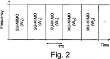
前述の議論において、多様な個別パイロットシンボルは多様な状況におけるSU−MIMOおよびMU−MIMOのために最適であることを論じた。この前提では、これらの2つのモード間で切替えを行う場合、SU−MIMOおよびMU−MIMOモード間の急な移行が生じるだろう。これを図2に示す。図2では、あるTTIにおいてその時点でのMIMOモードによる送信が止まり、すぐ次のTTIにおいて他のMIMOモードが始まる。SU−MIMOおよびMU−MIMOのための個別パイロットは、各々、所定の位相および振幅値により特徴づけられる所定の重み行列W1およびW2に関連付けられる。 In the foregoing discussion, it was discussed that various individual pilot symbols are optimal for SU-MIMO and MU-MIMO in various situations. Under this assumption, when switching between these two modes, a sudden transition between SU-MIMO and MU-MIMO modes will occur. This is shown in FIG. In FIG. 2, transmission in the MIMO mode at that time is stopped in a certain TTI, and another MIMO mode is started in the next TTI. The dedicated pilots for SU-MIMO and MU-MIMO are associated with predetermined weight matrices W 1 and W 2 that are characterized by predetermined phase and amplitude values, respectively.
図2に例示したソリューションには2つの欠点がある。第1に、切り替え時に未処理のHARQ再送信(もしあれば)は失われる、または遅延する可能性がある。これは、次のMIMOモードが始まった場合、同じユーザがすぐにスケジュールされないこともあるからである。もう一つの欠点は、新たなMIMOモードが適用されて一番目のTTIにおいて、ユーザ装置は以前のMIMOモードによるCQIを報告することである。このため、チャネルまたはセルオリエンテーション推定(予測)は、モード切替により誤った個別パイロットに基づいて行われ、少なくとも一番目のTTIにおいて、スケジューリング、パワー制御、およびリンクアダプテーションが適切なプリコーティング行列に基づいて行われないため、データスループットの低下を招くであろう。 The solution illustrated in FIG. 2 has two drawbacks. First, outstanding HARQ retransmissions (if any) at the time of switching may be lost or delayed. This is because the same user may not be scheduled immediately when the next MIMO mode begins. Another disadvantage is that in the first TTI when a new MIMO mode is applied, the user equipment reports CQI according to the previous MIMO mode. For this reason, channel or cell orientation estimation (prediction) is performed based on erroneous individual pilots due to mode switching, and scheduling, power control, and link adaptation are based on an appropriate pre-coating matrix at least in the first TTI. Since this is not done, the data throughput will be reduced.
そこで、本発明の目的は、シングルユーザおよびマルチユーザモード間の切換えを行う場合に、MIMOに基づく通信システムにおいてデータスループットを改善するための方法および構成を実現することである。 Accordingly, an object of the present invention is to realize a method and configuration for improving data throughput in a communication system based on MIMO when switching between single-user and multi-user modes.
この目的および他の目的は、複数の送信アンテナおよび複数の受信アンテナを有する通信ネットワークにおいて異なるシングルユーザモードおよびマルチユーザモードを切替えるために基地局が行う方法により実現される。本発明は、期間が複数のTTI(Transmission Time INterval)である準備段階を取り入れ、この準備段階中には、双方のモードに対応する適切なレファレンス信号(または所定シーケンス)が、これらのモードに関する各重み行列で基地局により送信される。この意図は、準備段階後に新たな送信モードが適用されたときに直ちに利用可能なスケジューリング情報を基地局が得られるように、ユーザ装置から新たな送信モードに関するMIMO関連フィードバック情報を回収および収集することである。基地局は、全て、または少なくともユーザ装置のグループがアクセスできるチャネルにより、準備段階の開始および期間長を直接または間接的に通知する。 This and other objectives are realized by the method performed by the base station to switch between different single-user mode and multi-user mode in a communication network having multiple transmit antennas and multiple receive antennas. The present invention incorporates a preparatory stage in which the period is a plurality of TTIs (Transmission Time Intervals), during which the appropriate reference signal (or a predetermined sequence) corresponding to both modes is provided for each of these modes. Sent by the base station in a weight matrix. The intent is to collect and collect MIMO related feedback information about the new transmission mode from the user equipment so that the base station can get the scheduling information available immediately when the new transmission mode is applied after the preparation phase. It is. The base station reports directly or indirectly the start of the preparation phase and the length of the period by means of a channel that is accessible by all or at least a group of user equipment.
また、本発明は、双方のモードに対応し各々のモードの重み行列によるリファレンス信号(または所定シーケンス)を上記準備段階中に受信し、新たなモードに関するフィードバックを、従前のモードによる通信を継続しつつ提供するユーザ装置による方法に関する。 In addition, the present invention receives a reference signal (or a predetermined sequence) corresponding to both modes in accordance with the weight matrix of each mode during the preparation stage, and continues communication in the previous mode with feedback regarding the new mode. It is related with the method by the user apparatus provided.
さらに、本発明は、上述した方法を実行するための手段を備える基地局およびユーザ装置において利用される構成に関する。 Furthermore, the present invention relates to a configuration used in a base station and user equipment comprising means for performing the method described above.
これにより、本発明は以下の効果を伴う。 Thereby, the present invention has the following effects.
本発明による第1の効果は、基地局がモード切替を実行する前にユーザ装置が新たなMIMOモードの準備およびCQIの測定を行うことができるので、特にSU−MIMOおよびMU−MIMOにおいて、MIMOモード間での円滑な移行を可能とすることである。 The first effect of the present invention is that, since the user equipment can prepare for a new MIMO mode and measure CQI before the base station performs mode switching, the MIMO is particularly effective in SU-MIMO and MU-MIMO. It is to enable a smooth transition between modes.
さらなる本発明による効果は、HARQ送信、特にHARQ再送信の損失を最小化できることである。 A further advantage of the present invention is that the loss of HARQ transmissions, in particular HARQ retransmissions, can be minimized.
他の効果によれば、本発明は、新たなMIMOモードによる送信が始まると直ちにネットワークが最適なデータスループットに関してベストなユーザをスケジューリングのために選択することを促進にする。 According to another advantage, the present invention facilitates the network to select the best user for scheduling for optimal data throughput as soon as transmission in a new MIMO mode begins.
本発明の他の目的、効果および新規な特徴は、特許請求の範囲および添付の図面と併せて、以下の本発明の詳細な説明から明らかになるであろう。 Other objects, advantages and novel features of the invention will become apparent from the following detailed description of the invention when taken in conjunction with the claims and the accompanying drawings.
本発明は、図面に示した複数の実施形態を参照しながら限定されない方法で説明される。
以下の説明では、E−UTRANシステムに焦点が当てられる。しかし、本発明は、個別リファレンス信号を利用するMIMOまたは類似のスキームが用いられる他の技術にも適用されることは当業者に認められるべきことである。E−UTRANは、ダウンリンクにおいてOFDMA技術を用いる。しかし、双方のMIMO技術は、OFDMA、CDMA、およびTDMAなどのいかなるアクセス技術にも利用することができる。これは、個別リファレンス信号を利用するIEEE802.16の仕様書によるシステムもまた包含する。 In the following description, the focus will be on the E-UTRAN system. However, it should be appreciated by those skilled in the art that the present invention applies to other techniques in which MIMO or similar schemes that utilize individual reference signals are used. E-UTRAN uses OFDMA technology in the downlink. However, both MIMO technologies can be utilized for any access technology such as OFDMA, CDMA, and TDMA. This also encompasses a system according to the IEEE 802.16 specification that utilizes individual reference signals.
この説明ではFDDに基づくE−UTRANシステムにおいてMIMOが共通リファレンス信号のみを利用することを想定するが、本発明は将来のFDD E−UTRANの充実にもまた利用できることを理解されたい。 Although this description assumes that MIMO uses only a common reference signal in an FDD-based E-UTRAN system, it should be understood that the present invention can also be used to enrich future FDD E-UTRAN.
以下の説明は、本発明の第1の観点としての準備段階に関する。 The following description relates to the preparation stage as the first aspect of the present invention.
SU−MIMOからMU−MIMOへの移行およびその逆は、N個のTTIからなる長さを有する準備段階(Dp)により特徴づけられる。準備段階においては、SU−MIMOおよびMU−MIMOで要求されるリファレンス信号(および他の関連既知シーケンス)が、各々の重み行列W1およびW2と関連付けられた各々の個別パイロットと共に送信される。準備段階の期間長は、標準化されていても(すなわち、固定の期間長であっても)、ブロードキャストメッセージ(半動的)においてユーザ装置に指示されても、共有制御(Shared Control)チャネル(動的)で送信されてもよい。 The transition from SU-MIMO to MU-MIMO and vice versa is characterized by a preparation phase (Dp) having a length of N TTIs. In the preparation phase, the reference signals (and other related known sequences) required in SU-MIMO and MU-MIMO are transmitted with each individual pilot associated with each weight matrix W 1 and W 2 . The period length of the preparation phase may be standardized (ie, a fixed period length), or may be instructed to the user equipment in a broadcast message (semi-dynamic), and may be shared control channel (dynamic May be transmitted.
準備段階は、実行中のHARQ処理を完了させるため、および、スケジューリング決定およびリンクアダプテーションを改善するために次のMIMOモードに関するチャネル推定情報(またはCQI)を受信および収集するために利用される。 The preparatory phase is utilized to receive and collect channel estimation information (or CQI) for the next MIMO mode to complete the ongoing HARQ process and to improve scheduling decisions and link adaptation.
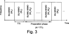
このため、本発明の方法によれば、SU−MIMOおよびMU−MIMOモード間の切換えは瞬間的に行われず、図3に示したように、少なくとも1または2以上のTTIからなる期間(Dp)を有する準備段階が存在する。図示したように、準備段階中は、SU−MIMOおよびMU−MIMOモードの双方に関して少なくともいくつかのリファレンス信号(または関連既知シーケンス)が対応する重み行列W1およびW2で送信される。これは、SU−MIMOおよびMU−MIMOモードとでリファレンス信号の位置が異なる(少なくとも周波数領域において)ことにより実現される。なお、重み行列W1およびW2は、リファレンス信号または既知シーケンスにのみ作用する。 For this reason, according to the method of the present invention, switching between SU-MIMO and MU-MIMO modes is not instantaneously performed, and as shown in FIG. 3, a period (Dp) composed of at least one or more TTIs. There is a preparatory stage with As shown, during the preparation phase, at least some reference signals (or associated known sequences) are transmitted in the corresponding weight matrices W 1 and W 2 for both SU-MIMO and MU-MIMO modes. This is realized by the position of the reference signal being different (at least in the frequency domain) between the SU-MIMO mode and the MU-MIMO mode. Note that the weight matrices W 1 and W 2 operate only on the reference signal or the known sequence.
準備段階中は、既に動作中のユーザはその時点での(先行する)MIMOモード(図3の例ではSU−MIMO)によりスケジュールされる。これにより、実行中のHARQ処理および未処理のHARQ再送信を完了することが可能となる。一方、準備段階中、ユーザは次の(後続の)MIMOモード(図3の例ではMU−MIMO)のための準備をすることができる。本発明による方法における準備の意は、特に、ユーザ装置が次のMIMOモードによるCQIを測定し、それをネットワークに報告できることである。これは、新たなMIMOモードが始動する時にネットワークが的確なユーザをスケジュールのために選択することを可能とする。準備段階は少なくとも1のTTIである。 During the preparation phase, already active users are scheduled in the current (preceding) MIMO mode (SU-MIMO in the example of FIG. 3). As a result, the HARQ process being executed and the unprocessed HARQ retransmission can be completed. On the other hand, during the preparation phase, the user can prepare for the next (subsequent) MIMO mode (MU-MIMO in the example of FIG. 3). The preparation in the method according to the invention is in particular that the user equipment can measure the CQI according to the next MIMO mode and report it to the network. This allows the network to select the correct user for the schedule when a new MIMO mode is started. The preparation phase is at least one TTI.
他の可能性のある準備段階の取り決めは、リファレンス信号を、新たなMIMOモードの重み行列(この例ではW2)を利用して、データ送信に利用されないバンド幅の一部において(図4に示したように)送信することである。 Another possible preparatory arrangement is to use the reference signal in a portion of the bandwidth not used for data transmission (see FIG. 4) using the new MIMO mode weight matrix (W 2 in this example). (As shown) to send.
準備段階の取り入れによる一つの結果が、双方のMIMOモードのためのリファレンス信号が送信されることに起因する追加的なオーバーヘッドである。しかし、リファレンス信号はシステムのバンド幅のとても小さな一部分の構成要素であるので、このオーバーヘッドによる影響はわずかである。一方、仮に準備段階を用いない場合、MIMOモード切替後の最初のいくつかのTTIで相当なスループット損失のリスクが存在する。 One result of incorporating the preparatory phase is additional overhead due to the transmission of reference signals for both MIMO modes. However, since the reference signal is a component of a very small part of the system bandwidth, the effect of this overhead is small. On the other hand, if the preparation stage is not used, there is a considerable risk of throughput loss in the first few TTIs after switching to the MIMO mode.
準備段階を設定する際にCQIレポートの遅延を考慮することは、新たなMIMOモードが始まった最初のTTIにおいて適切なCQIを利用可能とすることを確実にするので、重要である。CQIレポートの遅延は、ユーザ装置における測定遅延(標準化された)と、基地局での処理遅延(実装依存)との組み合わせである。ネットワークはこれらの全ての遅延を把握するので、準備段階の最適な期間は容易に設定することができる。典型的には、準備遅延は数TTI(2または3TTI)程度であろう。 Considering the CQI report delay when setting up the preparatory phase is important as it ensures that the appropriate CQI is available at the first TTI where a new MIMO mode has begun. The CQI report delay is a combination of a measurement delay (standardized) in the user equipment and a processing delay (implementation dependent) in the base station. Since the network keeps track of all these delays, the optimal period of the preparation phase can be easily set. Typically, the preparation delay will be on the order of a few TTIs (2 or 3 TTIs).
以下の説明は、本発明の第2の観点としての、上述した準備段階についての情報を提供するためのメカニズムの多様な選択肢に関する。 The following description relates to various options of the mechanism for providing information about the above-mentioned preparation steps as a second aspect of the present invention.
SU−MIMOおよびMU−MIMO間の切替えのための準備段階に関するルールは、規格において明示される必要がある。明示、選択、およびセル内のユーザ装置への準備段階の期間を通知のための考え得る選択肢は3つ存在する。3つの選択肢は、
・完全に静的な準備段階(事前定義されたルールによって)、
・完全に動的な準備段階(共有制御チャネルを介して通知)、および、
・半動的な準備段階(BCHおよび共有制御チャネルを介して通知)、を含む。
Rules regarding the preparatory stage for switching between SU-MIMO and MU-MIMO need to be specified in the standard. There are three possible options for notifying, selecting, and notifying the user equipment in the cell during the preparation phase. The three options are
A completely static preparatory stage (by predefined rules),
A fully dynamic preparation phase (notification via a shared control channel), and
Semi-dynamic preparation phase (notification via BCH and shared control channel).
完全に静的なアプローチを適用する場合、準備段階の長さ(Dp)は、N個のTTIに固定される。この長さは、全てのネットワーク装置がそれを利用できるよう、無線ネットワークにおいて統一される必要がある。この実施形態の変形例によれば、同じ値が全ての状況のために指定されても、異なる状況のために異なる値が指定されてもよい。さらに、任意の状況のために複数の値(Dp)を指定することも可能である。 When applying a fully static approach, the length of the preparation phase (Dp) is fixed to N TTIs. This length needs to be unified in the wireless network so that all network devices can use it. According to a variation of this embodiment, the same value may be specified for all situations, or different values may be specified for different situations. Furthermore, it is possible to specify multiple values (Dp) for any situation.
T0で表される準備段階(またはMIMO切り替え)が開始されるTTIを、切替の直前(例えば、準備段階開始の1つ前のTTI)に全てのユーザ装置がアクセス可能な適切な共有または共通チャネルで通知すれば足りる。通知される情報は、与えられた状況に関して規定されるDpの値が1つである場合、1ビットのみから構成される。これを以下の表1に示す。 Appropriate shared or common TTI where the preparation phase (or MIMO switching) represented by T 0 is started, which can be accessed by all user devices immediately before the switching (eg, the TTI immediately before the start of the preparation phase). It is enough to notify on the channel. The notified information is composed of only one bit when the value of D p defined for a given situation is one. This is shown in Table 1 below.

2以上のDpの値(例えば、K個の値)が規定される場合、シグナリングのオーバーヘッドが増加することになるが、準備段階の期間も通知するためにマルチレベルの信号が必要となる。ネットワークは、以下の表2に示すように、M(K≦2M)ビットを送信しなくてはならない。 When two or more Dp values (eg, K values) are defined, signaling overhead increases, but a multi-level signal is required to notify the preparatory period. The network must transmit M (K ≦ 2 M ) bits as shown in Table 2 below.
共有制御チャネルは、例えば、E−UTRANまたはUTRANでのHA−SCCHにおけるPDCCH(Physical Downlink Control CHannel)である。E−UTRANでは、セル送信バンド幅全体中で規定されたいくつかのサブキャリアにより、1番目、2番目または3番目のOFDMシンボルにおいて制御情報(PDCCH)が送信される。 The shared control channel is, for example, PDCCH (Physical Downlink Control Channel) in HA-SCCH in E-UTRAN or UTRAN. In E-UTRAN, control information (PDCCH) is transmitted in the first, second, or third OFDM symbol by several subcarriers defined in the entire cell transmission bandwidth.
完全に動的なアプローチを適用する場合、準備段階の長さ(Dp)は固定されず、各セルにおいて動的に決定され、上述した完全に静的なケースよりも柔軟なアプローチとすることができる。例えば、無線環境、トラフィック状況、および/または他の状態が他のMIMOモードへの切り替えに適しているとネットワークが把握した場合や、HARQ送信や再送信要求が無い場合、ネットワークは、1個のTTIのように、顕著に短い準備段階(Dp)を選択することができる。これは、準備段階が、次のMIMOモードによるCQIをユーザが測定するために必要だからである。一方、HARQ送信や再送信要求が要求される場合、ネットワークは長い準備長さ(Dp)を選択してもよい。 When applying a fully dynamic approach, the length of the preparation phase (D p ) is not fixed, but is determined dynamically in each cell, making the approach more flexible than the fully static case described above Can do. For example, if the network knows that the wireless environment, traffic conditions, and / or other conditions are suitable for switching to another MIMO mode, or if there is no HARQ transmission or retransmission request, the network As with TTI, a significantly shorter preparation stage (D p ) can be selected. This is because the preparation stage is necessary for the user to measure the CQI according to the next MIMO mode. On the other hand, when a HARQ transmission or a retransmission request is requested, the network may select a long preparation length (D p ).
この場合、T0で表される準備段階(またはMIMO切り替え)が開始されるTTIは、準備段階(Dp)と共に、全てのユーザ装置がアクセス可能ないくつかの共有または共通チャネルでユーザ装置に通知される必要がある(準備段階開始の直前に)。明らかな欠点は、(Dp)による追加的なシグナリングのオーバーヘッドが必要となることである。より詳細には、マルチレベルのシグナリング、すなわち2またはそれ以上のビットは不可避である。実際のビット数は、望まれの柔軟度に依存する。したがって、この方法は、シグナリングのオーバーヘッドと柔軟性とのトレードである。T0およびDpを伝送する共有制御チャネルは、例えば、E−UTRANまたはUTRANでのHA−SCCHにおけるPDCCHである。 In this case, the TTI in which the preparation phase (or MIMO switching) represented by T 0 is initiated, along with the preparation phase (D p ), is transmitted to the user equipment on several shared or common channels accessible to all user equipments. Need to be notified (just before the start of the preparation phase). The obvious drawback is that additional signaling overhead due to (D p ) is required. More particularly, multi-level signaling, ie 2 or more bits, is unavoidable. The actual number of bits depends on the desired flexibility. This method is therefore a trade-off between signaling overhead and flexibility. The shared control channel that transmits T 0 and D p is, for example, PDCCH in HA-SCCH in E-UTRAN or UTRAN.
半動的な準備段階は、上述した完全に静的なアプローチおよび完全に動的なアプローチの中間物である。半動的なアプローチによれば、準備段階の期間(Dp)は、BCH(Broadcast CHannel)により送信される。新たなセルを再選択するアイドルモード(または低RRC活動状態)の新参は、BCH情報をデコードするときにその時点でのDpの値を取得するだろう。ネットワークは、長い時間スケールでDpを変更し、BCH情報を修正することができる。Dpに何かしらの変化があった場合、ユーザ装置は、BCH情報の変化を解釈し、セルにおける新たなDpを取得することが要求される。他の方法は、新たなDpの値をRRCシグナリングを介して個別通信により接続モードのユーザ装置に通知することである。 The semi-dynamic preparation stage is an intermediate between the fully static approach and the fully dynamic approach described above. According to the semi-dynamic approach, the preparatory period (D p ) is transmitted by BCH (Broadcast Channel). Newcomer in idle mode to reselect a new cell (or low RRC activity state) will get the value of D p at the time when decoding BCH information. Network changes the D p over a timescale can modify the BCH information. If there is something changes in D p, the user equipment interprets the changes in the BCH information, it is required to obtain a new D p in the cell. Another method is to notify the user device in the connected mode of the new value of D p by individual communication via RRC signaling.
前述のケースでは、T0で表される準備段階(またはMIMO切り替え)が開始されるTTIは、全てのユーザ装置に連絡可能ないくつかの共有共通制御(Shared Common Control)チャネルでユーザ装置に通知されるべきである。この場合、通知情報(T0に関する)は、上記の表1に従う1ビットにより構成される。この情報は、準備段階が開始するTTIのみを示す。このため、共有制御チャネルのオーバーヘッドは抑制される(上述の静的なケースと同様に)。上記と同一の共有制御チャネルは、T0関連情報の伝送に利用される。概して、このスキームは、いく分の柔軟性を提供し、同時に、伴うオーバーヘッドを完全に動的なケースより減少させる。 In the above case, the TTI where the preparation phase represented by T 0 (or MIMO switching) is initiated informs the user equipment on several shared common control channels that can contact all user equipment. It should be. In this case, the notification information (about T 0) is composed of 1 bit according to Table 1 above. This information only indicates the TTI at which the preparation phase starts. This reduces the overhead of the shared control channel (similar to the static case described above). Same shared control channel and above are used to transmit T 0 related information. In general, this scheme provides some flexibility and at the same time reduces the associated overhead over the fully dynamic case.
図5は、データストリームを送受信するためのアンテナ131a、131bを備えるユーザ装置とデータストリームを送受信するための、1または2のアンテナ121a、121bを有するアンテナアレンジメント、と接続された複数の基地局120からなるMIMO通信ネットワーク100を示している。ここでは、2×2のMIMOシステムが示されているが、当業者であれば、アンテナの数は変化してもよいことが理解されるべきである。
FIG. 5 shows a plurality of
上述したステップは、例えば図5に概略的に示したMIMOシステムにおける、所定の重み行列によるユニークなリファレンス信号シーケンスを利用して同時に同じユーザにデータを送信するために全てのアンテナを利用する無線基地局に関して簡単に説明される。重み行列は、所定の位相および振幅値により特徴づけられる。 The above-described steps are for example a radio base using all antennas to transmit data to the same user simultaneously using a unique reference signal sequence with a predetermined weight matrix in the MIMO system schematically shown in FIG. A brief description of the station. The weight matrix is characterized by a predetermined phase and amplitude value.
多数または1のユーザに同時に送信される位相および振幅は、異なる重み行列を有する他のレファレンス信号シーケンスを利用する。シングルユーザ送信およびマルチユーザ送信間の切換えは半動的または動的である。シングルユーザからマルチユーザモード、またはその逆の切り替えは、
−1または2以上のTTIで構成される準備段階中に、シングルユーザおよびマルチユーザMIMOの各々に対応するリファレンス信号または既知シーケンスを各々の重み行列で送信し、
−セル内の全てのユーザ装置に、少なくとも準備段階の開始および期間(特定の実施形態においては)を通知すること、
を含む。
The phase and amplitude transmitted simultaneously to multiple or one user utilizes other reference signal sequences with different weight matrices. Switching between single-user transmission and multi-user transmission is semi-dynamic or dynamic. Switching from single user to multi-user mode, or vice versa,
During the preparatory phase consisting of −1 or more TTIs, a reference signal or known sequence corresponding to each of the single-user and multi-user MIMO is transmitted in each weight matrix;
Notifying all user equipments in the cell at least the start and duration (in a particular embodiment) of the preparation phase;
including.
準備段階中、既存のMIMOモードと後続(次の)モードのためのリファレンス信号はセル送信バンド幅の異なる位置に制限されるものの、シングルユーザおよびマルチユーザモードに関するリファレンス信号は、セル送信バンド幅の全体中に分散される。事前定義されたルールにより1または2以上の準備長さのパターンが規定される。さらに、セル内の全てのユーザ装置に、次のTTIにおける準備段階の開始、および必要に応じ、規定された準備長さのうちで実際の準備長さのポインタを示す、1または2以上のビットの情報が共有制御チャネルにより送信される。また、セル内の全てのユーザ装置に、次のTTIにおける準備段階の開始、および絶対的な準備長さを示すマルチレベルのシグナリングを共有制御チャネルにより送信することも可能である。 During the preparation phase, the reference signal for the existing MIMO mode and the subsequent (next) mode is limited to different positions in the cell transmission bandwidth, while the reference signal for single user and multi-user mode is Distributed throughout. One or more preparation length patterns are defined by predefined rules. Furthermore, one or more bits indicating to all user equipments in the cell the start of the preparation phase in the next TTI and, if necessary, a pointer to the actual preparation length of the prescribed preparation length Are transmitted through the shared control channel. It is also possible to transmit the multi-level signaling indicating the start of the preparation phase in the next TTI and the absolute preparation length to all user apparatuses in the cell through the shared control channel.
次のTTIにおける準備段階の開始を示す1ビットの情報を全てのユーザに送信するに加え、準備段階のパターンが、セル内の全てのユーザ装置にブロードキャストチャネルにより送信されても、ユーザ装置に個別的に共有データチャネルにより送信されてもよい。準備段階中、無線基地局は、HARQ再送信、およびその時点でのMIMOモードによる実行中のセッションが可能であれば先の送信を完了させようとする。無線基地局は、準備段階中にユーザ装置からの新たな(後続の)MIMOモードに関するチャネル品質フィードバック情報を利用し、それを新たなMIMOモードによるデータ送信が開始したときの適切なスケジューリング、パワー制御、リンクアダプテーション、および他の無線リソース割当て技術のために利用する。 In addition to transmitting 1-bit information indicating the start of the preparation phase in the next TTI to all users, even if the pattern of the preparation phase is transmitted over the broadcast channel to all user devices in the cell, Alternatively, it may be transmitted via a shared data channel. During the preparation phase, the radio base station attempts to complete the previous transmission if the HARQ retransmission and a session currently in progress in the MIMO mode are possible. The radio base station uses the channel quality feedback information regarding the new (subsequent) MIMO mode from the user equipment during the preparation phase, and uses it to perform appropriate scheduling and power control when data transmission in the new MIMO mode starts. , Link adaptation, and other radio resource allocation techniques.
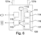
図6は、本発明による基地局120(または通信ゲートウェイ)を示す。この基地局は、少なくとも1の処理構成111と、例えば準備段階中にユーザ装置から受信されたフィードバック情報の収集および記憶のために利用可能少なくとも1のメモリ112(揮発性、および/または不揮発性)を備える。さらに、基地局は、ユーザ装置130へ向かう通信インターフェース113と、インフラストラクチャーネットワークに向かう通信インターフェース115と、を備える。加えて、基地局は、1または2以上のTTIの長さからなる準備段階中に、双方のモードに対応するリファレンス信号を各モードの重み行列で送信するための準備をする手段116と、受信エリア内のすべての受信装置に準備段階の開始および期間を示すシグナリング情報を共通チャネルで送信するための準備をする手段117とを備える。さらに、基地局は、ユーザ装置から受信されたフィードバック情報に基づいて準備段階後にユーザ装置をスケジューリングするためのスケジューラ114を備えてもよい。上記の多くの機能は、例えば処理構成111によって実行される。
FIG. 6 shows a base station 120 (or communication gateway) according to the present invention. The base station has at least one
これにより、準備段階中、ユーザ装置は、新たなMIMOモードのチャネル特性およびチャネル品質を推定することができ、また、必要であれば、対応するチャネル品質を無線基地局に報告することができる。 Thereby, during the preparation stage, the user apparatus can estimate the channel characteristics and channel quality of the new MIMO mode, and can report the corresponding channel quality to the radio base station if necessary.
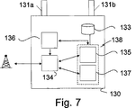
無線基地局がシングルユーザからマルチユーザモードに切り替える場合またはその逆の場合に、1または2以上の送信アンテナ131a、131bから送信信号を受信する図7に概略的に示したユーザ装置130は、
−1または2以上のTTIからなる準備期間中に、シングルユーザおよびマルチユーザMIMOの双方に対応する各々の重み行列によるリファレンス信号または既知シーケンスを受信する受信部137と、
−無線基地局から共有制御チャネルにより準備段階の開始および期間を示すシグナリング情報を受信して正しく解釈する手段と(処理部132により行われてもよい。)、
−従前のモードによる通信を維持しつつ、新たな送信モードに関するフィードバックを提供するための手段136と、
を備える。
When the radio base station switches from a single user to a multi-user mode or vice versa, the
A receiving
Means for receiving and correctly interpreting signaling information indicating the start and duration of the preparation stage from the radio base station via the shared control channel (may be performed by the processing unit 132);
-
Is provided.
ユーザ装置は、さらに、メモリ部133、ユーザインターフェース部134、パワーサプライ135、およびアンテナ131a、131bを備える。これらのユーザ装置の要素は当業者によく知られている。
The user device further includes a
図8は、無線基地局120により実行される本発明による方法のフローチャートを示す。この方法は、通信ネットワーク100における異なるMIMO送信モード間、すなわちシングルユーザモードおよびマルチユーザモード間またはその逆の切換えを意図するものである。この方法によれば、無線基地局120が受信エリア内の全ての受信ユーザ装置130に、少なくとも準備段階の開始の通知を含むシグナリング情報を共通または共有チャネルで送信し(81)、準備段階の開始した後は、準備段階中(82)、双方のMIMO送信モードに対応するリファレンス信号を各モードの重み行列により送信する(83)。準備段階後、MIMO送信モードは、従前、すなわち準備段階の前および準備段階中に適用されるモードから、新たに、すなわち準備段階後に適用されるモードに切り替えられる。さらに無線基地局120は、準備段階中、ユーザ装置130からのMIMOフィードバック情報を収集し(84)、この情報を、新たなMIMO送信モードが適用される準備段階後に行われるダウンリンク送信に利用されるストリームの最適なフィードバックを有するユーザ装置のスケジューリングを準備するために利用する(85)。
FIG. 8 shows a flowchart of the method according to the invention performed by the
図9は、ユーザ装置130により実行される本発明による方法のフローチャートを示す。この方法は、通信ネットワーク100における異なるMIMO送信モード間、すなわちシングルユーザモードおよびマルチユーザモード間またはその逆の切換えをサポートすることを意図するものである。この方法によれば、共通または共有チャネルにより送信された少なくとも準備段階の開始の通知を含むシグナリング情報をユーザ装置130が受信して解釈する(91)。準備段階の開始後、ユーザ装置130は各モードに対応する各モードの重み行列によるリファレンス信号を受信し(93)、従前、すなわち準備段階前に適用されたMIMO送信モードによつ通信を維持しつつ、新たなMIMOモード、すなわち準備段階後に適用されるMIMOモードによるダウンリンク送信のためのデータストリームに関するMIMOフィードバック情報を提供する(94)。
FIG. 9 shows a flow chart of the method according to the present invention performed by the
MIMO技術は、複数の送信アンテナおよび複数の受信アンテナを利用することにより、空間多重化、空間ダイバーシティ、および/またはビームフォーミング利得をもたらす。SIMOおよびMISOはMIMOの特別なケースであるので、本発明はSIMOおよびMISOにも適用可能である。SIMOによれば、複数の受信アンテナは1の送信アンテナからの受信信号をコヒーレントに結合する。MISOによれば、複数の送信アンテナおよび1の受信アンテナを利用することにより送信ダイバーシティが実現される。 MIMO technology provides spatial multiplexing, spatial diversity, and / or beamforming gain by utilizing multiple transmit antennas and multiple receive antennas. Since SIMO and MISO are special cases of MIMO, the present invention is also applicable to SIMO and MISO. According to SIMO, a plurality of receiving antennas coherently combine received signals from one transmitting antenna. According to MISO, transmission diversity is realized by using a plurality of transmission antennas and one reception antenna.
略記
UE: User Equipment
UTRAN: UMTS Terrestrial Radio Access
Network
E−UTRAN:Evolved UTRAN
TTI: Transmission Time Interval
MIMO: Multiple Input Multiple Output
BCH: Broadcast CHannel
PDCCH: Physical Downlink Control
CHannel
HS−SCCH:High Speed Signaling Control
CHannel
CQI: Channel Quality Indicator
SU−MIMO:Single User MIMO
MU−MIMO:Multi−User MIMO
PARC: Per Antenna Rate Control
SIC: Successive Interference
Cancellation
DFT: Discrete Fourier Transform
Los: Line of Sight
Abbreviation UE: User Equipment
UTRAN: UMTS Terrestrial Radio Access
Network
E-UTRAN: Evolved UTRAN
TTI: Transmission Time Interval
MIMO: Multiple Input Multiple Output
BCH: Broadcast Channel
PDCCH: Physical Downlink Control
Channel
HS-SCCH: High Speed Signaling Control
Channel
CQI: Channel Quality Indicator
SU-MIMO: Single User MIMO
MU-MIMO: Multi-User MIMO
PARC: Per Antenna Rate Control
SIC: Successive Interference
Cancellation
DFT: Discrete Fourier Transform
Los: Line of Light
Claims (5)
少なくとも準備段階の開始の通知を含むシグナリング情報を、共通または共有チャネルで受信エリア内の全てのユーザ受信装置に送信するステップと、
1または2以上のTTIからなる前記準備段階中に、前記MIMO送信モードの双方に対応するリファレンス信号を各々のモードのための重み行列で送信するステップと、
を含むことを特徴とする、方法。A method by a base station for switching between different MIMO transmission modes in a communication network , the communication network comprising a plurality of transmit antennas and a plurality of receive antennas, the modes comprising a single user mode and a multi-user mode,
Transmitting signaling information including notification of at least the start of the preparation phase to all user receiving devices in the reception area on a common or shared channel;
Transmitting a reference signal corresponding to both of the MIMO transmission modes in a weighting matrix for each mode during the preparatory phase consisting of one or more TTIs;
A method comprising the steps of:
前記準備段階後に行われるダウンリンク送信に利用されるストリームの最適なフィードバックを有するユーザ装置のスケジューリングを準備するステップと、
をさらに含む、請求項1に記載の方法。Collecting MIMO feedback information from user equipment during the preparation phase;
Preparing scheduling of user equipment with optimal feedback of streams utilized for downlink transmission performed after said preparation step;
The method of claim 1, further comprising:
共通または共有チャネルで送信された少なくとも準備段階の開始の通知を含むシグナリング情報を受信して解釈するステップと;
1または2以上のTTIからなる前記準備段階中に、前記モードの双方に対応する、前記モードの各々のための各重み行列によるリファレンス信号を受信するステップと;
従前に適用されるMIMO送信モードによる通信を維持する一方で、新たなMIMO送信モードに関してダウンリンク送信に利用されるデータストリームのMIMOフィードバック情報を前記準備段階中に供給するステップと;
を含むことを特徴とする、方法。A method by a user equipment comprising a plurality of antennas for receiving signals in different MIMO transmission modes in a communication network, wherein the different MIMO transmission modes include a single user mode and a multi-user mode,
Receiving and interpreting signaling information transmitted on a common or shared channel, including at least a notification of the start of the preparation phase;
Receiving a reference signal with each weight matrix for each of said modes, corresponding to both of said modes, during said preparatory phase consisting of one or more TTIs;
Providing MIMO feedback information of the data stream used for downlink transmission during the preparation phase while maintaining communication according to the previously applied MIMO transmission mode;
A method comprising the steps of:
1または2以上のTTIからなる準備段階中に、前記モードの双方に対応し、前記モードのための各重み行列により構成される送信リファレンス信号を用意する手段と;
少なくとも準備段階の開始の通知を含むシグナリング情報を、共通または共有チャネルで受信エリア内の全てのユーザ受信装置に送信するための用意をする手段と;
を備えることを特徴とする、構成。A configuration used in a base station in a communication network , wherein the base station communicates with a plurality of antennas, the configuration is provided for switching between different modes in the communication network, and the different modes are single users. Mode and multi-user mode,
In one or more of the TTI Tona Ru Preparation phase, corresponding to both the mode, means for providing a transmit reference signal composed of the weighting matrix for the mode;
Means for preparing signaling information including at least a notification of the start of the preparation phase to be transmitted to all user receiving devices in the reception area on a common or shared channel;
The structure characterized by comprising.
1または2以上のTTIからなる準備段階中に、前記モードの双方に対応し、前記モードの各重み行列によるリファレンス信号を受信する手段と;
従前のモードによる通信を維持する一方で、新たなモードに関するフィードバックを行うための手段と;
を備えることを特徴とする、構成。A configuration utilized in a user equipment, wherein the configuration is provided for receiving signals in different modes in a communication network, the modes including a single user mode and a multi-user mode;
Means for receiving a reference signal corresponding to both of the modes and corresponding to each weight matrix during the preparatory phase consisting of one or more TTIs;
Means for providing feedback on the new mode while maintaining communication in the previous mode;
The structure characterized by comprising.
Applications Claiming Priority (3)
| Application Number | Priority Date | Filing Date | Title |
|---|---|---|---|
| SE0700766-9 | 2007-03-26 | ||
| SE0700766 | 2007-03-26 | ||
| PCT/SE2008/050277 WO2008118067A2 (en) | 2007-03-26 | 2008-03-13 | Preparation phase for switching between su-mimo and mu-mimo |
Publications (3)
| Publication Number | Publication Date |
|---|---|
| JP2010523041A JP2010523041A (en) | 2010-07-08 |
| JP2010523041A5 JP2010523041A5 (en) | 2011-04-07 |
| JP5113239B2 true JP5113239B2 (en) | 2013-01-09 |
Family
ID=39789135
Family Applications (1)
| Application Number | Title | Priority Date | Filing Date |
|---|---|---|---|
| JP2010500872A Expired - Fee Related JP5113239B2 (en) | 2007-03-26 | 2008-03-13 | Methods and configurations for communication networks |
Country Status (4)
| Country | Link |
|---|---|
| US (1) | US8798012B2 (en) |
| EP (1) | EP2127135B1 (en) |
| JP (1) | JP5113239B2 (en) |
| WO (1) | WO2008118067A2 (en) |
Families Citing this family (28)
| Publication number | Priority date | Publication date | Assignee | Title |
|---|---|---|---|---|
| KR20080043899A (en) * | 2006-11-15 | 2008-05-20 | 삼성전자주식회사 | Apparatus and method for a transmission mode feedback in communication systems |
| JP5113239B2 (en) * | 2007-03-26 | 2013-01-09 | テレフオンアクチーボラゲット エル エム エリクソン(パブル) | Methods and configurations for communication networks |
| ES2536765T3 (en) * | 2007-06-27 | 2015-05-28 | Unwired Planet International Limited | Method and provisions in a telecommunications system |
| KR101537591B1 (en) * | 2008-04-07 | 2015-07-20 | 엘지전자 주식회사 | Method for mode adaptation in MIMO system |
| US8406171B2 (en) * | 2008-08-01 | 2013-03-26 | Texas Instruments Incorporated | Network MIMO reporting, control signaling and transmission |
| CN101741443A (en) * | 2008-11-05 | 2010-06-16 | 中兴通讯股份有限公司 | Method and device for regulating in multiple-input multiple-output mode |
| CN101754330A (en) * | 2008-12-04 | 2010-06-23 | 华为技术有限公司 | Multi-input multi-output mode control method, device and system |
| WO2010072020A1 (en) | 2008-12-22 | 2010-07-01 | Huawei Technologies Co., Ltd. | Method for signalling in a wireless communication system |
| US8693429B2 (en) | 2009-03-31 | 2014-04-08 | Qualcomm Incorporated | Methods and apparatus for generation and use of reference signals in a communications system |
| CN102077502B (en) | 2009-04-30 | 2013-04-24 | 华为技术有限公司 | Data retransmission method and user equipment |
| CN101902305B (en) * | 2009-05-25 | 2013-10-30 | 富士通株式会社 | Communication device, communication method and base station |
| US8515363B2 (en) | 2009-06-19 | 2013-08-20 | Sharp Kabushiki Kaisha | Systems and methods for providing a reduced power amplifier transmission mode |
| US8768362B2 (en) | 2009-06-22 | 2014-07-01 | Sharp Kabushiki Kaisha | Communication system, mobile station, base station, and communication method |
| US9042331B2 (en) * | 2009-09-09 | 2015-05-26 | Lg Electronics Inc. | Method and apparatus for transmitting control information in WLAN system |
| WO2011131210A1 (en) * | 2010-04-20 | 2011-10-27 | Telecom Italia S.P.A. | Method and system for wireless communications, corresponding network and computer |
| US8824386B2 (en) * | 2010-05-05 | 2014-09-02 | Mediatek Inc. | Method and system of operating a multi-user system |
| US8891652B2 (en) | 2010-06-24 | 2014-11-18 | Qualcomm Incorporated | Structured MIMO codebook |
| JP5585306B2 (en) | 2010-08-25 | 2014-09-10 | ソニー株式会社 | BASE STATION, RADIO COMMUNICATION DEVICE, RADIO COMMUNICATION SYSTEM, RADIO COMMUNICATION METHOD, AND PROGRAM |
| CN102387593B (en) | 2010-09-06 | 2014-05-07 | 电信科学技术研究院 | Communication method adopting space-division multiple access (SDMA) and base station |
| WO2013139528A1 (en) * | 2012-03-23 | 2013-09-26 | Nokia Siemens Networks Oy | Methods, devices and computer program products for receiving downlink transmissions from more than one network transceiver device |
| US8761039B2 (en) * | 2012-03-28 | 2014-06-24 | Apple Inc. | Adaptive generation of channel quality indicators (CQIs) based on a current communication scenario |
| JP6147329B2 (en) * | 2012-04-17 | 2017-06-14 | テレフオンアクチーボラゲット エルエム エリクソン(パブル) | Method and node for maintaining a wireless connection in a wireless communication network |
| KR101972950B1 (en) * | 2012-07-19 | 2019-04-26 | 삼성전자 주식회사 | Apparatus and method of power control for multi-beam forming in wireless communication system |
| US20150207602A1 (en) * | 2014-01-21 | 2015-07-23 | Qualcomm Incorporated | Pilot mapping for mu-mimo |
| JP5958592B2 (en) * | 2015-04-14 | 2016-08-02 | ソニー株式会社 | Mobile station and base station |
| US10348523B2 (en) * | 2015-06-11 | 2019-07-09 | Lg Electronics Inc. | Reference signal configuration method for V2V communication in wireless communication system, and apparatus therefor |
| US10135591B2 (en) | 2016-08-19 | 2018-11-20 | Qualcomm Incorporated | Techniques for improving URLLC communications in new radio |
| CN109150452B (en) * | 2017-06-16 | 2021-03-09 | 电信科学技术研究院 | Method for indicating pilot frequency precoding mode, network side equipment and terminal |
Family Cites Families (20)
| Publication number | Priority date | Publication date | Assignee | Title |
|---|---|---|---|---|
| US5909471A (en) * | 1997-08-08 | 1999-06-01 | Arraycomm, Inc. | Method and system for rapid initial control signal detection in a wireless communications system |
| IL151937A0 (en) * | 2002-02-13 | 2003-07-31 | Witcom Ltd | Near-field spatial multiplexing |
| US7929921B2 (en) * | 2003-06-10 | 2011-04-19 | Motorola Mobility, Inc. | Diversity control in wireless communications devices and methods |
| KR100929094B1 (en) * | 2003-09-20 | 2009-11-30 | 삼성전자주식회사 | System and method for dynamic resource allocation in a communication system using orthogonal frequency division multiple access scheme |
| US7437166B2 (en) * | 2003-09-24 | 2008-10-14 | Telefonaktiebolaget Lm Ericsson (Publ) | Reducing shared downlink radio channel interference by transmitting to multiple mobiles using multiple antenna beams |
| US7830976B2 (en) | 2004-07-16 | 2010-11-09 | Qualcomm Incorporated | Iterative channel and interference estimation with dedicated pilot tones for OFDMA |
| US20060067263A1 (en) * | 2004-09-30 | 2006-03-30 | Qinghua Li | Techniques to manage multiple receivers |
| US8571132B2 (en) * | 2004-12-22 | 2013-10-29 | Qualcomm Incorporated | Constrained hopping in wireless communication systems |
| US20070058595A1 (en) * | 2005-03-30 | 2007-03-15 | Motorola, Inc. | Method and apparatus for reducing round trip latency and overhead within a communication system |
| US7872981B2 (en) * | 2005-05-12 | 2011-01-18 | Qualcomm Incorporated | Rate selection for eigensteering in a MIMO communication system |
| US7751510B2 (en) | 2005-07-26 | 2010-07-06 | Qualcomm Incorporated | Simplified channel and interference estimation with dedicated pilot tones for OFDMA |
| US8638771B2 (en) * | 2005-08-12 | 2014-01-28 | Qualcomm Incorporated | Transmission structure supporting multi-user scheduling and MIMO transmission |
| KR100819285B1 (en) * | 2006-03-16 | 2008-04-02 | 삼성전자주식회사 | Method for transmiting/receiving feedback information in a multi-antenna system of selporting multi-user and system thereof |
| US9130791B2 (en) * | 2006-03-20 | 2015-09-08 | Qualcomm Incorporated | Uplink channel estimation using a signaling channel |
| US8059609B2 (en) * | 2006-03-20 | 2011-11-15 | Qualcomm Incorporated | Resource allocation to support single-user and multi-user MIMO transmission |
| US8914015B2 (en) * | 2006-03-20 | 2014-12-16 | Qualcomm Incorporated | Grouping of users for MIMO transmission in a wireless communication system |
| US7689177B2 (en) * | 2006-05-24 | 2010-03-30 | Samsung Electronics Co., Ltd. | Method and apparatus for transmitting/receiving feedback information and system supporting the same in a multi-user multi-antenna system |
| US8363606B2 (en) * | 2006-09-05 | 2013-01-29 | Qualcomm Incorporated | Method and apparatus for data and control multiplexing |
| JP5113239B2 (en) * | 2007-03-26 | 2013-01-09 | テレフオンアクチーボラゲット エル エム エリクソン(パブル) | Methods and configurations for communication networks |
| US7885176B2 (en) * | 2007-06-01 | 2011-02-08 | Samsung Electronics Co., Ltd. | Methods and apparatus for mapping modulation symbols to resources in OFDM systems |
-
2008
- 2008-03-13 JP JP2010500872A patent/JP5113239B2/en not_active Expired - Fee Related
- 2008-03-13 EP EP08724224.4A patent/EP2127135B1/en active Active
- 2008-03-13 US US12/527,964 patent/US8798012B2/en active Active
- 2008-03-13 WO PCT/SE2008/050277 patent/WO2008118067A2/en active Application Filing
Also Published As
| Publication number | Publication date |
|---|---|
| EP2127135B1 (en) | 2015-01-21 |
| JP2010523041A (en) | 2010-07-08 |
| US8798012B2 (en) | 2014-08-05 |
| WO2008118067A3 (en) | 2008-11-13 |
| EP2127135A2 (en) | 2009-12-02 |
| WO2008118067A2 (en) | 2008-10-02 |
| EP2127135A4 (en) | 2014-01-22 |
| US20100091743A1 (en) | 2010-04-15 |
Similar Documents
| Publication | Publication Date | Title |
|---|---|---|
| JP5113239B2 (en) | Methods and configurations for communication networks | |
| JP6463721B2 (en) | Method and apparatus for feeding back channel state information in a wireless communication system | |
| JP6301417B2 (en) | Method and apparatus for feeding back channel state information in a wireless communication system | |
| JP6208814B2 (en) | Method and apparatus for reporting channel state information in a wireless communication system | |
| US9276783B2 (en) | Uplink transmission mode switching in single user multiple-input communication | |
| US8670719B2 (en) | Multi-point opportunistic beamforming with selective beam attenuation | |
| US7756099B2 (en) | Method and system for selecting antennas adaptively in OFDMA networks | |
| JP4889532B2 (en) | Base station apparatus and method in mobile communication system | |
| KR101736951B1 (en) | Apparatus and method for transmission of uplink sounding reference signals in a wireless network | |
| RU2533808C2 (en) | Transmitter (versions) and signal transmission method (versions) | |
| JP5249322B2 (en) | Data transmission method in multi-antenna system | |
| KR20080036939A (en) | System and method for generating reference signals in a wireless communication system | |
| KR20080005396A (en) | Systems and methods for control channel signaling | |
| WO2010032810A1 (en) | Base station apparatus, user equipment and precoding method | |
| WO2009060650A1 (en) | Method for selecting antennas in a spatial division multiple access (sdma) wireless network | |
| KR101448639B1 (en) | A method for transmitting a data by collaborating of a plurality of base station in a multi-cell environments and a method for receiving using the same | |
| EP2299751B1 (en) | Mobile station apparatus, communication system, and communication method | |
| WO2016114699A1 (en) | Resource scheduling of uplink resources | |
| TWI444000B (en) | Method and apparatus for transmitting feedback request and method and apparatus for receiving feedback request in wireless communication system | |
| KR20120023635A (en) | Method and apparatus for transmitting/receiving a sounding reference signal in a wireless communication system |
Legal Events
| Date | Code | Title | Description |
|---|---|---|---|
| A521 | Request for written amendment filed |
Free format text: JAPANESE INTERMEDIATE CODE: A523 Effective date: 20110208 |
|
| A621 | Written request for application examination |
Free format text: JAPANESE INTERMEDIATE CODE: A621 Effective date: 20110208 |
|
| A131 | Notification of reasons for refusal |
Free format text: JAPANESE INTERMEDIATE CODE: A131 Effective date: 20120828 |
|
| A521 | Request for written amendment filed |
Free format text: JAPANESE INTERMEDIATE CODE: A523 Effective date: 20120906 |
|
| TRDD | Decision of grant or rejection written | ||
| A01 | Written decision to grant a patent or to grant a registration (utility model) |
Free format text: JAPANESE INTERMEDIATE CODE: A01 Effective date: 20121002 |
|
| A01 | Written decision to grant a patent or to grant a registration (utility model) |
Free format text: JAPANESE INTERMEDIATE CODE: A01 |
|
| A61 | First payment of annual fees (during grant procedure) |
Free format text: JAPANESE INTERMEDIATE CODE: A61 Effective date: 20121011 |
|
| FPAY | Renewal fee payment (event date is renewal date of database) |
Free format text: PAYMENT UNTIL: 20151019 Year of fee payment: 3 |
|
| R150 | Certificate of patent or registration of utility model |
Ref document number: 5113239 Country of ref document: JP Free format text: JAPANESE INTERMEDIATE CODE: R150 Free format text: JAPANESE INTERMEDIATE CODE: R150 |
|
| R250 | Receipt of annual fees |
Free format text: JAPANESE INTERMEDIATE CODE: R250 |
|
| R250 | Receipt of annual fees |
Free format text: JAPANESE INTERMEDIATE CODE: R250 |
|
| R250 | Receipt of annual fees |
Free format text: JAPANESE INTERMEDIATE CODE: R250 |
|
| R250 | Receipt of annual fees |
Free format text: JAPANESE INTERMEDIATE CODE: R250 |
|
| R250 | Receipt of annual fees |
Free format text: JAPANESE INTERMEDIATE CODE: R250 |
|
| R250 | Receipt of annual fees |
Free format text: JAPANESE INTERMEDIATE CODE: R250 |
|
| LAPS | Cancellation because of no payment of annual fees |