JP4889532B2 - Base station apparatus and method in mobile communication system - Google Patents
Base station apparatus and method in mobile communication system Download PDFInfo
- Publication number
- JP4889532B2 JP4889532B2 JP2007073726A JP2007073726A JP4889532B2 JP 4889532 B2 JP4889532 B2 JP 4889532B2 JP 2007073726 A JP2007073726 A JP 2007073726A JP 2007073726 A JP2007073726 A JP 2007073726A JP 4889532 B2 JP4889532 B2 JP 4889532B2
- Authority
- JP
- Japan
- Prior art keywords
- base station
- station apparatus
- precoding vector
- user
- communication
- Prior art date
- Legal status (The legal status is an assumption and is not a legal conclusion. Google has not performed a legal analysis and makes no representation as to the accuracy of the status listed.)
- Expired - Fee Related
Links
Images


Classifications
-
- H—ELECTRICITY
- H01—ELECTRIC ELEMENTS
- H01Q—ANTENNAS, i.e. RADIO AERIALS
- H01Q1/00—Details of, or arrangements associated with, antennas
- H01Q1/12—Supports; Mounting means
- H01Q1/22—Supports; Mounting means by structural association with other equipment or articles
- H01Q1/24—Supports; Mounting means by structural association with other equipment or articles with receiving set
- H01Q1/241—Supports; Mounting means by structural association with other equipment or articles with receiving set used in mobile communications, e.g. GSM
- H01Q1/246—Supports; Mounting means by structural association with other equipment or articles with receiving set used in mobile communications, e.g. GSM specially adapted for base stations
-
- H—ELECTRICITY
- H04—ELECTRIC COMMUNICATION TECHNIQUE
- H04B—TRANSMISSION
- H04B7/00—Radio transmission systems, i.e. using radiation field
- H04B7/02—Diversity systems; Multi-antenna system, i.e. transmission or reception using multiple antennas
- H04B7/04—Diversity systems; Multi-antenna system, i.e. transmission or reception using multiple antennas using two or more spaced independent antennas
- H04B7/06—Diversity systems; Multi-antenna system, i.e. transmission or reception using multiple antennas using two or more spaced independent antennas at the transmitting station
- H04B7/0613—Diversity systems; Multi-antenna system, i.e. transmission or reception using multiple antennas using two or more spaced independent antennas at the transmitting station using simultaneous transmission
- H04B7/0615—Diversity systems; Multi-antenna system, i.e. transmission or reception using multiple antennas using two or more spaced independent antennas at the transmitting station using simultaneous transmission of weighted versions of same signal
- H04B7/0619—Diversity systems; Multi-antenna system, i.e. transmission or reception using multiple antennas using two or more spaced independent antennas at the transmitting station using simultaneous transmission of weighted versions of same signal using feedback from receiving side
- H04B7/0621—Feedback content
- H04B7/0634—Antenna weights or vector/matrix coefficients
-
- H—ELECTRICITY
- H04—ELECTRIC COMMUNICATION TECHNIQUE
- H04B—TRANSMISSION
- H04B7/00—Radio transmission systems, i.e. using radiation field
- H04B7/02—Diversity systems; Multi-antenna system, i.e. transmission or reception using multiple antennas
- H04B7/04—Diversity systems; Multi-antenna system, i.e. transmission or reception using multiple antennas using two or more spaced independent antennas
- H04B7/06—Diversity systems; Multi-antenna system, i.e. transmission or reception using multiple antennas using two or more spaced independent antennas at the transmitting station
- H04B7/0613—Diversity systems; Multi-antenna system, i.e. transmission or reception using multiple antennas using two or more spaced independent antennas at the transmitting station using simultaneous transmission
- H04B7/0615—Diversity systems; Multi-antenna system, i.e. transmission or reception using multiple antennas using two or more spaced independent antennas at the transmitting station using simultaneous transmission of weighted versions of same signal
- H04B7/0619—Diversity systems; Multi-antenna system, i.e. transmission or reception using multiple antennas using two or more spaced independent antennas at the transmitting station using simultaneous transmission of weighted versions of same signal using feedback from receiving side
- H04B7/0636—Feedback format
- H04B7/0645—Variable feedback
- H04B7/065—Variable contents, e.g. long-term or short-short
-
- H—ELECTRICITY
- H04—ELECTRIC COMMUNICATION TECHNIQUE
- H04B—TRANSMISSION
- H04B7/00—Radio transmission systems, i.e. using radiation field
- H04B7/02—Diversity systems; Multi-antenna system, i.e. transmission or reception using multiple antennas
- H04B7/04—Diversity systems; Multi-antenna system, i.e. transmission or reception using multiple antennas using two or more spaced independent antennas
- H04B7/06—Diversity systems; Multi-antenna system, i.e. transmission or reception using multiple antennas using two or more spaced independent antennas at the transmitting station
- H04B7/0613—Diversity systems; Multi-antenna system, i.e. transmission or reception using multiple antennas using two or more spaced independent antennas at the transmitting station using simultaneous transmission
- H04B7/0615—Diversity systems; Multi-antenna system, i.e. transmission or reception using multiple antennas using two or more spaced independent antennas at the transmitting station using simultaneous transmission of weighted versions of same signal
- H04B7/0619—Diversity systems; Multi-antenna system, i.e. transmission or reception using multiple antennas using two or more spaced independent antennas at the transmitting station using simultaneous transmission of weighted versions of same signal using feedback from receiving side
- H04B7/0658—Feedback reduction
- H04B7/066—Combined feedback for a number of channels, e.g. over several subcarriers like in orthogonal frequency division multiplexing [OFDM]
-
- H—ELECTRICITY
- H04—ELECTRIC COMMUNICATION TECHNIQUE
- H04B—TRANSMISSION
- H04B7/00—Radio transmission systems, i.e. using radiation field
- H04B7/02—Diversity systems; Multi-antenna system, i.e. transmission or reception using multiple antennas
- H04B7/04—Diversity systems; Multi-antenna system, i.e. transmission or reception using multiple antennas using two or more spaced independent antennas
- H04B7/06—Diversity systems; Multi-antenna system, i.e. transmission or reception using multiple antennas using two or more spaced independent antennas at the transmitting station
- H04B7/0686—Hybrid systems, i.e. switching and simultaneous transmission
- H04B7/0689—Hybrid systems, i.e. switching and simultaneous transmission using different transmission schemes, at least one of them being a diversity transmission scheme
-
- H—ELECTRICITY
- H04—ELECTRIC COMMUNICATION TECHNIQUE
- H04W—WIRELESS COMMUNICATION NETWORKS
- H04W72/00—Local resource management
- H04W72/04—Wireless resource allocation
-
- H—ELECTRICITY
- H04—ELECTRIC COMMUNICATION TECHNIQUE
- H04B—TRANSMISSION
- H04B7/00—Radio transmission systems, i.e. using radiation field
- H04B7/02—Diversity systems; Multi-antenna system, i.e. transmission or reception using multiple antennas
- H04B7/04—Diversity systems; Multi-antenna system, i.e. transmission or reception using multiple antennas using two or more spaced independent antennas
- H04B7/06—Diversity systems; Multi-antenna system, i.e. transmission or reception using multiple antennas using two or more spaced independent antennas at the transmitting station
- H04B7/0613—Diversity systems; Multi-antenna system, i.e. transmission or reception using multiple antennas using two or more spaced independent antennas at the transmitting station using simultaneous transmission
- H04B7/0615—Diversity systems; Multi-antenna system, i.e. transmission or reception using multiple antennas using two or more spaced independent antennas at the transmitting station using simultaneous transmission of weighted versions of same signal
- H04B7/0619—Diversity systems; Multi-antenna system, i.e. transmission or reception using multiple antennas using two or more spaced independent antennas at the transmitting station using simultaneous transmission of weighted versions of same signal using feedback from receiving side
- H04B7/0621—Feedback content
- H04B7/0632—Channel quality parameters, e.g. channel quality indicator [CQI]
-
- H—ELECTRICITY
- H04—ELECTRIC COMMUNICATION TECHNIQUE
- H04B—TRANSMISSION
- H04B7/00—Radio transmission systems, i.e. using radiation field
- H04B7/02—Diversity systems; Multi-antenna system, i.e. transmission or reception using multiple antennas
- H04B7/04—Diversity systems; Multi-antenna system, i.e. transmission or reception using multiple antennas using two or more spaced independent antennas
- H04B7/06—Diversity systems; Multi-antenna system, i.e. transmission or reception using multiple antennas using two or more spaced independent antennas at the transmitting station
- H04B7/0613—Diversity systems; Multi-antenna system, i.e. transmission or reception using multiple antennas using two or more spaced independent antennas at the transmitting station using simultaneous transmission
- H04B7/0667—Diversity systems; Multi-antenna system, i.e. transmission or reception using multiple antennas using two or more spaced independent antennas at the transmitting station using simultaneous transmission of delayed versions of same signal
- H04B7/0671—Diversity systems; Multi-antenna system, i.e. transmission or reception using multiple antennas using two or more spaced independent antennas at the transmitting station using simultaneous transmission of delayed versions of same signal using different delays between antennas
-
- H—ELECTRICITY
- H04—ELECTRIC COMMUNICATION TECHNIQUE
- H04W—WIRELESS COMMUNICATION NETWORKS
- H04W72/00—Local resource management
- H04W72/12—Wireless traffic scheduling
Description
本発明は移動通信システムにおける基地局装置、ユーザ装置及び方法に関する。 The present invention relates to a base station apparatus, a user apparatus and a method in a mobile communication system.
この種の技術分野では次世代移動通信方式に関する研究開発が急ピッチで進められている。W-CDMAの標準化団体3GPPは、W-CDMAやHSDPA、HSUPAの後継となる通信方式がとして、ロングタームエボリューション(LTE: Long Term Evolution)を検討している。LTEでは無線アクセス方式として下りリンクにOFDM方式を、上りリンクにSC-FDMA(Single-Carrier Frequency Division Multiple Access)を予定している (例えば、非特許文献1参照)。
直交周波数分割多重接続(OFDM)方式は、周波数帯域を複数の狭い周波数帯域(サブキャリア)に分割し、各周波数帯上にデータを載せて伝送を行うマルチキャリア方式であり、サブキャリアを周波数上に、一部重なりあいながらも互いに干渉することなく密に並べることで、高速伝送を実現し、周波数の利用効率を上げることができる。
In this type of technical field, research and development related to next-generation mobile communication systems are proceeding at a rapid pace. The standardization organization 3GPP of W-CDMA is considering Long Term Evolution (LTE) as a communication system that succeeds W-CDMA, HSDPA, and HSUPA. In LTE, as a radio access scheme, the OFDM scheme is planned for the downlink and SC-FDMA (Single-Carrier Frequency Division Multiple Access) is planned for the uplink (for example, see Non-Patent Document 1).
The Orthogonal Frequency Division Multiple Access (OFDM) system is a multi-carrier system that divides a frequency band into multiple narrow frequency bands (subcarriers) and transmits data on each frequency band. Moreover, by arranging them closely without interfering with each other even though they partially overlap, it is possible to realize high-speed transmission and increase the frequency utilization efficiency.
シングルキャリアFDMA(SC-FDMA)は、周波数帯域を分割し、複数の端末間で異なる周波数帯域を用いて伝送することで、端末間の干渉を低減することができるシングルキャリア方式の伝送方式である。SC−FDMAでは、送信電力の変動が小さくなる特徴を持つことから、端末の低消費電力化及び広いカバレッジを実現できる。 Single-carrier FDMA (SC-FDMA) is a single-carrier transmission method that can reduce interference between terminals by dividing the frequency band and transmitting using different frequency bands among multiple terminals. . Since SC-FDMA has a feature that fluctuations in transmission power are reduced, it is possible to realize low power consumption and wide coverage of a terminal.
LTEは、上りリンク、下りリンクともに1つないし2つ以上の物理チャネルを複数のユーザ装置で共有して通信を行うシステムである。上記複数のユーザ装置で共有されるチャネルは、一般に共有チャネルと呼ばれ、LTEでは上り共有物理チャネル(PUSCH: Physical Uplink Shared Channel)により上りリンクの通信が、下り共有物理チャネル(PDSCH: Physical Downlink Shared Channel)により下り通信が行われる。 LTE is a system in which one or two or more physical channels are shared by a plurality of user apparatuses for both uplink and downlink. The channel shared by the plurality of user apparatuses is generally called a shared channel, and in LTE, uplink communication is performed using an uplink shared physical channel (PUSCH: Physical Uplink Shared Channel), and a downlink shared physical channel (PDSCH: Physical Downlink Shared). Channel) is used for downlink communication.
これらの共有チャネルを用いた通信システムではサブフレーム(Sub-frame)(LTEでは1ms)毎に、どのユーザ装置に対して上記共有チャネルを割り当てるかをシグナリングする必要がある。このシグナリングに用いられる制御チャネルは、LTEでは、物理下りリンク制御チャネル(PDCCH: Physical Donwlink Control Channel)または、下りL1/L2制御チャネル(DL-L1/L2 Control Channel)と呼ばれる。上記物理下りリンク制御チャネルの情報には、例えば、下りスケジューリング情報又はダウンリンクスケジューリングインフォメーション(Downlink Scheduling Information)、送達確認情報(ACK/NACK: Acknowledgement information)、上りリンクスケジューリンググラント(Uplink Scheduling Grant)、オーバロードインジケータ(Overload Indicator)、送信電力制御コマンドビット(Transmission Power Control Command Bit)等が含まれる(例えば、非特許文献2参照)。 In a communication system using these shared channels, it is necessary to signal to which user apparatus the shared channel is allocated for each sub-frame (1 ms in LTE). The control channel used for this signaling is called a physical downlink control channel (PDCCH) or a downlink L1 / L2 control channel (DL-L1 / L2 Control Channel) in LTE. The physical downlink control channel information includes, for example, downlink scheduling information or downlink scheduling information (Downlink Scheduling Information), acknowledgment information (ACK / NACK), uplink scheduling grant (Uplink Scheduling Grant), A load indicator (Overload Indicator), a transmission power control command bit (Transmission Power Control Command Bit), etc. are included (for example, refer nonpatent literature 2).
上記下りスケジューリング情報や上りリンクスケジューリンググラントが、どのユーザ装置に対して上記共有チャネルを割り当てるかをシグナリングするための情報に相当する。上記下りスケジューリング情報には、例えば、下りリンクの共有チャネルに関する、下りリンクのリソースブロック(RB: Resource Block)の割り当て情報、UEのID、MIMOが行われる場合のストリームの数、プリコーディングベクトル(Precoding Vector)に関する情報、データサイズ、変調方式、HARQ(Hybrid Automatic Repeat reQuest)に関する情報等が含まれる。また、上記上りリンクスケジューリンググラントには、例えば、上りリンクの共有チャネルに関する、上りリンクのリソースの割り当て情報、UEのID、データサイズ、変調方式、上りリンクの送信電力情報、アップリンクMIMO(Uplink MIMO)におけるデモジュレーションレファレンスシグナル(Demodulation Reference Signal)の情報等が含まれる。 The downlink scheduling information and the uplink scheduling grant correspond to information for signaling which user apparatus is assigned the shared channel. The downlink scheduling information includes, for example, downlink resource block (RB: Resource Block) allocation information, UE ID, number of streams when MIMO is performed, and precoding vector (Precoding vector) for downlink shared channels. Information on Vector), data size, modulation scheme, information on HARQ (Hybrid Automatic Repeat reQuest), and the like are included. The uplink scheduling grant includes, for example, uplink resource allocation information, UE ID, data size, modulation scheme, uplink transmission power information, uplink MIMO (Uplink MIMO) related to the uplink shared channel. ) Includes information of a demodulation reference signal (Demodulation Reference Signal).
マルチインプットマルチアウトプット(MIMO)方式は、通信に複数のアンテナを用いることで伝送信号の高速化及び/又は高品質化を図るマルチアンテナ方式の通信である。更に、送信信号のストリームを複製し、複製された各ストリームを適切な重みと共に合成して送信することで、指向性の制御されたビームで通信相手に信号を送ることができる。これは、プリコーディング方式と呼ばれ、使用される重み(ウエイト)はプリコーディングベクトルと呼ばれる。 The multi-input multi-output (MIMO) system is a multi-antenna system communication that uses a plurality of antennas for communication to increase the speed and / or quality of transmission signals. Furthermore, by duplicating the stream of the transmission signal and combining and transmitting each of the duplicated streams with appropriate weights, it is possible to send a signal to the communication partner with a beam having a controlled directivity. This is called a precoding scheme, and the weight used is called a precoding vector.
図1はプリコーディングが行われる様子を模式的に示す。2つのストリーム(送信信号1,2)はそれぞれコピー部で2系統に複製され、各系統でプリコーディングベクトルが乗算され、合成された後に送信される。プリコーディングベクトルは受信側(ユーザ装置)からのフィードバックに基づいて、より適切な値になるよう適応的に制御される。上述したようにLTEでは下りリンクにOFDM方式が使用され、かなり広範囲にわたる帯域がシステム帯域として用意される。その結果、周波数軸方向のフェージング変動が大きくなるかもしれない。
FIG. 1 schematically shows how precoding is performed. The two streams (
図2は周波数軸方向でフェージング変動が生じている様子を示す。送信信号(ストリーム)は各サブキャリアにマッピングされて送信される。図示の例では4ストリームが送信されることを想定している。周波数に依存してフェージングの影響は異なるので、プリコーディングベクトルもそのような変動に適合して決定されることが好ましいかもしれない。例えば、図示の例では、5MHzのシステム帯域に25個のリソースブロックが含まれており、5リソースブロック毎に異なるプリコーディングベクトルが各ストリームに用意される。言い換えれば或るストリームに関し、リソースブロック5つ分の周波数範囲については同じプリコーディングベクトルが適用される。同じプリコーディングベクトルが適用されるリソースブロック数を少なくすることで、大きなフェージング変動に対応することができる。しかしながらそのようにすると、プリコーディングベクトルのフィードバック制御ループ数も多く用意しなければならなくなり、制御負担(オーバーヘッド)が大きくなってしまう。特に高速に移動しているユーザ装置については、信号処理遅延に起因して追従性の悪化が懸念されるかもしれない。 FIG. 2 shows how fading fluctuations occur in the frequency axis direction. A transmission signal (stream) is transmitted after being mapped to each subcarrier. In the illustrated example, it is assumed that four streams are transmitted. Depending on the frequency, the effect of fading differs, so it may be preferable that the precoding vector is also determined to accommodate such variations. For example, in the illustrated example, 25 resource blocks are included in a 5 MHz system band, and a different precoding vector is prepared for each stream for each 5 resource block. In other words, the same precoding vector is applied to a frequency range corresponding to five resource blocks for a certain stream. By reducing the number of resource blocks to which the same precoding vector is applied, it is possible to cope with large fading fluctuations. However, if this is done, a large number of feedback control loops for the precoding vector must be prepared, and the control burden (overhead) increases. Especially for user devices moving at high speed, there may be a concern that the follow-up performance is deteriorated due to the signal processing delay.
一方、遅延ダイバーシチ又はサイクリック遅延ダイバーシチ(CDD: Cyclic Delay Diversity)と呼ばれる技術も提案されている。これは、送信信号をアンテナ数分複製し、複製部から各アンテナに至るまでの経路遅延が意図的に異なるように設定される。複数のアンテナからは時間的に異なるタイミングで同じ信号が送信される。受信側ではそれらは複数のパスとして受信され、それらを合成することでダイバーシチ効果を期待することができる。 On the other hand, a technique called delay diversity or cyclic delay diversity (CDD) is also proposed. This is set so that the transmission signal is duplicated by the number of antennas, and the path delay from the duplication unit to each antenna is intentionally different. The same signal is transmitted from a plurality of antennas at different timings. On the receiving side, they are received as a plurality of paths, and by combining them, a diversity effect can be expected.
図3はCDD方式とプリコーディング方式を2アンテナ系に適用した例を示す。
図4は図2と同様に4ストリームの送信信号が下りリンクで送信される場合に、周波数軸方向でフェージング変動が生じている様子を示す。周波数に依存してフェージングの影響は異なるので、CDD方式の遅延量もそのような変動に適合して決定されることが好ましい。しかしながらそのような観点から遅延量を正確に決定しようとする技術は十分に研究されていない。 FIG. 4 shows a state in which fading fluctuation occurs in the frequency axis direction when four streams of transmission signals are transmitted in the downlink, as in FIG. Since the influence of fading differs depending on the frequency, it is preferable that the delay amount of the CDD system is also determined in accordance with such fluctuations. However, a technique for accurately determining the delay amount from such a viewpoint has not been sufficiently studied.
ところで、プリコーディングは信号に何らかのウエイトを乗算するものであるが、これは周波数軸上で何らかの位相回転を信号に与えることに対応する。CDDは特定の複製系列に時間遅延を与えるが、これも周波数軸上で見れば何らかの位相回転を信号にあたることに相当する。 By the way, precoding multiplies a signal by some weight, and this corresponds to giving the signal some phase rotation on the frequency axis. CDD gives a time delay to a specific replication sequence, and this also corresponds to applying some phase rotation to the signal on the frequency axis.
図4の例では各ストリームについてリソースブロック毎に遅延量に相当する重みが存在する様子を示す。図示の例では、ストリーム1について第1リソースブロックにはウエイトw1が適用され、別のリソースブロックではw1と位相がφだけ異なるw2が適用されている。以下同様にストリーム1について位相がw1と2φだけ異なるw3、3φだけ異なるw4等が適用されている。説明の簡明化を図るため、ストリーム2の第1リソースブロックに適用されるウエイトw2は、ストリーム1の第2リソースブロックに適用されるウエイトに等しい。
The example of FIG. 4 shows a state in which a weight corresponding to the delay amount exists for each resource block for each stream. In the illustrated example, the weight w1 is applied to the first resource block for the
従ってプリコーディング方式とCDD方式とを組み合わせる場合には、プリコーディングベクトル及び遅延量を別個独立に決定することはできず、総合的に決定する必要がある。しかしながらプリコーディングベクトル及び遅延量をそのような観点から総合的に決める技術は十分に研究されていない。 Therefore, when the precoding scheme and the CDD scheme are combined, the precoding vector and the delay amount cannot be determined independently, but must be determined comprehensively. However, a technique for comprehensively determining the precoding vector and the delay amount from such a viewpoint has not been sufficiently studied.
上述したようにプリコーディングベクトルが過剰に細かく制御されると、フィードバック制御負担が過剰に大きくなり、スループットに悪影響を及ぼしてしまう。また、CDD方式における遅延量が適切に設定されなかった場合は、伝送品質の悪化をもたらしてしまう。 As described above, when the precoding vector is excessively finely controlled, the feedback control burden becomes excessively large, which adversely affects the throughput. In addition, if the delay amount in the CDD method is not set appropriately, the transmission quality deteriorates.
本発明の課題は、プリコーディング方式を使用するマルチアンテナ通信及び遅延ダイバーシチを行う通信をサポートする移動通信システムにおいて、プリコーディングベクトルのフィードバック制御負担の適正化及び伝送品質の向上を図ることである。 An object of the present invention is to optimize the feedback control burden of a precoding vector and improve transmission quality in a mobile communication system that supports multi-antenna communication using a precoding scheme and communication that performs delay diversity.
本発明で使用される基地局装置は、プリコーディング方式を使用するマルチアンテナ通信及び遅延ダイバーシチを行う通信をサポートする移動通信システムで使用される。基地局装置は、下り通信を要求する1以上のユーザに割り当てるリソースを決定するスケジューリング手段と、各ユーザ装置からのフィードバック信号に応じて、複数のアンテナに適用するプリコーディングベクトルを決定する手段と、所定数のリソースブロック毎にプリコーディングベクトルのフィードバック制御を行うか否かを、各ユーザの要求する下りデータ量に応じてユーザ毎に決定する通信方式決定手段と、スケジューリング手段で決定されたリソースで、前記複数のアンテナから下り信号を送信する手段とを有する。前記通信方式決定手段は、プリコーディングベクトルのフィードバック制御が、システム帯域中のリソースブロックに共通に行われる場合に、遅延ダイバーシチを下り通信に使用するか否かも決定する。 The base station apparatus used in the present invention is used in a mobile communication system that supports multi-antenna communication using a precoding scheme and communication that performs delay diversity. The base station apparatus determines scheduling resources to be allocated to one or more users who request downlink communication, means for determining precoding vectors to be applied to a plurality of antennas according to feedback signals from each user apparatus, Whether to perform feedback control of the precoding vector for each predetermined number of resource blocks, depending on the amount of downlink data requested by each user, communication method determining means and resources determined by the scheduling means And means for transmitting a downlink signal from the plurality of antennas. The communication scheme determining means also determines whether or not to use delay diversity for downlink communication when feedback control of a precoding vector is performed in common for resource blocks in a system band.
本発明によれば、プリコーディング方式を使用するマルチアンテナ通信及び遅延ダイバーシチを行う通信をサポートする移動通信システムにおいて、プリコーディングベクトルのフィードバック制御負担の適正化及び伝送品質の向上を図ることができる。 ADVANTAGE OF THE INVENTION According to this invention, in the mobile communication system which supports the communication which performs multi-antenna communication which uses a precoding system, and delay diversity, the optimization of the feedback control burden of a precoding vector and improvement of transmission quality can be aimed at.
図5は本発明の一実施例による基地局装置のブロック図を示す。図5には、各ユーザ毎の上りリンク信号の復調及び復号部502、下りリンクスケジューラ504、プリコーディング法選択部506、ユーザデータチャネル生成部508、プリコーディング部510、周波数領域位相回転部512、下りリンク(L1/L2)制御チャネル生成部514、送信ダイバーシチ用変調部516、共通パラメータ設定部520、報知チャネル生成部522、送信ダイバーシチ用変調部524、直交リファレンス信号生成部526及びOFDM信号生成部530が描かれている。
FIG. 5 shows a block diagram of a base station apparatus according to an embodiment of the present invention. FIG. 5 shows uplink signal demodulation and
各ユーザ毎の上りリンク信号の復調及び復号部502は、受信された上りリンク信号を復調及び復号する。上りリンク信号には制御チャネル、データチャネルだけでなくランダムアクセスチャネル(RACH)が含まれてもよい。復調及び復号されたデータチャネルは、ユーザデータとして上位のネットワークに伝送される。制御チャネルには、下りリファレンス信号の受信品質を示す情報(CQI)、過去に下りリンクで伝送されたデータチャネルに対する送達確認情報(ACK/NACK)等が含まれてよい。RACH又は他の制御チャネルである、通信を要求する信号には、その通信に要求される各種パラメータの値が含まれる。パラメータの具体例は、ユーザの希望する伝送品質や伝送速度、ユーザの希望するストリーム数、ユーザの希望するプリコーディングベクトル、ユーザの希望するCDD方式の遅延量(遅延量に等価な周波数領域における位相角でもよい)等である。また、上り制御チャネルには、プリコーディング方式におけるフィードバック信号も含まれる。
The uplink signal demodulation and
下りリンクスケジューラ504は、各ユーザから報告されたCQI等の情報に基づいて、下りリンクにおける無線リソースの割り当てを計画する。スケジューラ504は、割り当てユーザ決定部、MCS決定部、プリコーディングベクトル決定部及び周波数領域位相回転量決定部を有する。 The downlink scheduler 504 plans downlink radio resource allocation based on information such as CQI reported from each user. The scheduler 504 includes an allocation user determination unit, an MCS determination unit, a precoding vector determination unit, and a frequency domain phase rotation amount determination unit.
割り当てユーザ決定部は、CQIの優劣等に基づいて下り通信を希望するユーザの内、1以上のユーザを選択する。 The assigned user determining unit selects one or more users among users who desire downlink communication based on superiority or inferiority of CQI.
MCS(Modulation and channel Coding Scheme)決定部は、適応変調及びチャネル符号化(AMC: Automatic Modulation and channel Coding)が行われる場合に、選択されたユーザ宛の下りデータチャネルに適用されるデータ変調方式及びチャネル符号化率を決定する。より具体的には、データ変調方式及びチャネル符号化率の所定の組み合わせの内、適切な組み合わせの番号(MCS番号)が指定される。 MCS (Modulation and channel Coding Scheme) decision unit, when adaptive modulation and channel coding (AMC: Automatic Modulation and channel Coding) is performed, the data modulation scheme applied to the downlink data channel addressed to the selected user and Determine the channel coding rate. More specifically, an appropriate combination number (MCS number) is designated among predetermined combinations of data modulation schemes and channel coding rates.
プリコーディングベクトル決定部は、ユーザからのフィードバック信号に基づいて、そのユーザに対する下り通信に使用されるプリコーディングベクトルを決定する。本実施例では、プリコーディングベクトルは、例えば5MHzのようなシステム帯域に含まれる例えば25個のリソースブロック全てに共通に設定されてもよいし、或いは、5リソースブロック毎に異なるように設定されてもよい。何れが設定されるかはプリコーディング法選択部506で決定される。システム帯域は5MHzだけでなく、10MHz,20MHz等適切な様々な帯域でもよい。
The precoding vector determination unit determines a precoding vector used for downlink communication for the user based on a feedback signal from the user. In this embodiment, the precoding vector may be set in common to, for example, all 25 resource blocks included in a system band such as 5 MHz, or may be set to be different for every 5 resource blocks. Also good. Which is set is determined by the precoding
周波数領域位相回転量決定部は、サイクリック遅延ダイバーシチ(CDD)方式が行われる場合に、各アンテナに至る各系列に如何なる遅延量が設定されるべきかが決定される。時間軸における遅延量τは、周波数軸上における何らかの位相回転角φτに対応する。 When the cyclic delay diversity (CDD) method is performed, the frequency domain phase rotation amount determination unit determines what delay amount should be set for each series reaching each antenna. The delay amount τ on the time axis corresponds to some phase rotation angle φ τ on the frequency axis.
プリコーディング法選択部506は、ユーザから通知された情報に基づいて、そのユーザ宛の下り通信で、プリコーディングベクトルのフィードバック制御をどのように行うかを決定する。ユーザから通知された情報は、典型的には下り通信のデータ量であるが、他の情報を参照してもよい。本実施例では、プリコーディングベクトルのフィードバック制御は、(1)システム帯域に含まれる全てのリソースブロックに共通になされるモードと、(2)システム帯域に含まれるリソースブロックの内、連続する所定数個(例えば、5個)のリソースブロック毎に多数のフィードバックループが用意されるモードとが用意されている。本実施例では、ユーザの要求する下り通信のデータ量が比較的多い場合は(1)のモードが選択され、それが比較的少ない場合には(2)のモードが選択される。後述されるように、後者のモードは基準モードとCDDモードに分けられる。
Based on the information notified from the user, the precoding
ユーザデータチャネル生成部508は、各ユーザ装置宛の下りデータチャネル(PDSCH)を、選択されたMCS及び選択されたプリコーディング法に基づいて作成する。
The user data
プリコーディング部510は、特定のユーザ宛のデータチャネルを複数系列に複製し、複数系列の各々に適切なプリコーディングベクトル(重み)を適用し、出力する。
周波数領域位相回転部512は、プリコーディングベクトルで重み付けされた複数の信号系列各々に所定の位相回転を与えて出力する。所定の位相回転角は、サイクリック遅延ダイバーシチ(CDD)方式が適用されない場合には0に設定されるが、CDD方式が適用される場合にはCDD方式における遅延量τに対応する位相角φτである。
The frequency domain
下りリンク(L1/L2)制御チャネル生成部514は、下りリンクの低レイヤ制御チャネル(L1/L2制御チャネル)を作成する。下りリンクL1/L2制御チャネルは、一般的には、下り又は上りスケジューリング情報、MIMO情報、送達確認情報(ACK/NACK)、再送制御情報(HARQ)、送信電力制御(TPC)コマンドビット等を含む。下り又は上りスケジューリング情報は、データチャネルのリソースブロックや適用されるMCS等を特定する。図示の例では、下りL1/L2制御チャネルに、選択されたプリコーディングベクトル及びCDD方式が適用された場合の位相回転量の情報が含まれる。
The downlink (L1 / L2) control
送信ダイバーシチ用変調部516は、複数のアンテナから下りL1/L2制御チャネルを送信するための変調を行う。一例として送信ダイバーシチは、時空間ブロック符号化(STBC: Space Time Block Coding)で行われてもよいし、周波数空間ブロック符号化(SFBC: Space Frequency Block Coding)で行われてもよい。
The transmission
共通パラメータ設定部520は、セル内の全てのユーザに共通するパラメータを用意する。本実施例では特にそのセルで使用される又は使用されてもよいプリコーディングベクトル、そのセルで使用される又は使用されてもよい遅延量(位相回転量)が用意される。
The common
報知チャネル生成部522は、共通パラメータ設定部520で用意されたプリコーディングベクトル及び/又は遅延量の値を含む報知チャネル(BCH)を作成する。
The broadcast
送信ダイバーシチ用変調部524は、複数のアンテナから報知チャネルを送信するための変調を行う。一例として送信ダイバーシチは、時空間ブロック符号化(STBC)や周波数空間ブロック符号化(SFBC)等で行われてもよい。
The transmission
直交リファレンス信号生成部526は、そのセルで使用されるリファレンス信号を用意する。
The orthogonal reference
OFDM信号生成部530は、高速逆フーリエ変換等を行うことで、或るアンテナから送信されるOFDM方式の送信信号を作成する。
The OFDM
図6は本発明の一実施例によるユーザ装置のブロック図を示す。図6には、OFDM信号復調部602、直交リファレンス信号レプリカ生成部603、チャネル推定部604、L1/L2制御チャネル復調及び復号部606、報知チャネル復調及び復号部608、乗算部610、データチャネル復調及び復号部612、プリコーディングベクトル候補生成部614、CDDに基づく周波数領域位相回転量生成部616、推定部618、上りリンクL1/L2制御チャネル生成部620、上りリンクデータチャネル生成部622、SC-FDMA変調部624が示されている。
FIG. 6 shows a block diagram of a user equipment according to an embodiment of the present invention. 6 shows an
OFDM信号復調部602は、ガードインターバルの除去及び高速フーリエ変換等を行うことで、受信したOFDM方式の信号からリファレンス信号、報知チャネル、下りL1/L2制御チャネル、データチャネル等を抽出する。
The OFDM
直交リファレンス信号レプリカ生成部603は、リファレンス信号のレプリカを用意し、チャネル推定部604に与える。
The orthogonal reference signal
チャネル推定部604は、送信アンテナ及び/又は受信アンテナ毎に、受信した下りリファレンス信号に基づいてチャネル推定を行う。説明の便宜上、チャネル推定結果を「A」で表す。
The
L1/L2制御チャネル復調及び復号部606は、チャネル推定値に基づいて、下りL1/L2制御チャネルを復調及び復号する。上述したようにL1/L2制御チャネルには様々な情報が含まれているかもしれないが、図示の例では特に、MCS(選択されたデータ変調方式及びチャネル符号化率)、使用されたプリコーディングベクトル、CDD方式が適用された場合に使用された遅延量(に相当する周波数領域の位相回転量))に関する情報がL1/L2制御チャネルから抽出される。説明の便宜上、これらの情報を「B」とする。 The L1 / L2 control channel demodulation and decoding unit 606 demodulates and decodes the downlink L1 / L2 control channel based on the channel estimation value. As described above, various information may be included in the L1 / L2 control channel, but in the illustrated example, in particular, MCS (selected data modulation scheme and channel coding rate), precoding used Information regarding the amount of delay used when the vector and CDD methods are applied (corresponding to the amount of phase rotation in the frequency domain) is extracted from the L1 / L2 control channel. For convenience of explanation, these pieces of information are referred to as “B”.
報知チャネル復調及び復号部608も、チャネル推定値に基づいて、報知チャネルを復調及び復号する。報知チャネルにも様々な情報が含まれているかもしれないが、図示の例では特に、プリコーディングベクトルのフィードバック制御が所定数個のリソースブロック毎に行われる場合の「所定数」が何であるか(周波数方向のプリコーディング解像度)、CDD方式が適用された場合に如何なる遅延量(それに対応する周波数領域の位相回転量)が何であるかを示す情報が、報知チャネルから抽出される。説明の便宜上、これらの情報を「C」とする。 The broadcast channel demodulation and decoding unit 608 also demodulates and decodes the broadcast channel based on the channel estimation value. Although various information may be included in the broadcast channel, in the illustrated example, in particular, what is the “predetermined number” when the feedback control of the precoding vector is performed for each predetermined number of resource blocks? (Precoding resolution in the frequency direction) and information indicating what delay amount (phase rotation amount in the corresponding frequency domain) is extracted from the broadcast channel when the CDD scheme is applied. For convenience of explanation, this information is assumed to be “C”.
乗算部610は、情報「B」に基づいて、チャネル推定値を補正する。具体的には、チャネル推定値にプリコーディングベクトルを乗算し、必要に応じてCDD方式の遅延量に対応する位相回転量を加えることで、チャネル推定値が補正される。 Multiplier 610 corrects the channel estimation value based on information “B”. Specifically, the channel estimation value is corrected by multiplying the channel estimation value by a precoding vector and adding a phase rotation amount corresponding to the delay amount of the CDD method as necessary.
データチャネル復調及び復号部612は、補正後のチャネル推定値及び情報「B」に基づいて、データチャネルを復調及び復元する。データチャネルには再生されたユーザデータに加えて、上位レイヤの制御データが含まれていてもよい。この制御データには例えば、そのユーザ装置用に決定されたプリコーディングベクトルの制御法を示す情報が含まれてもよい。説明の便宜上、この情報を「D」とする。
The data channel demodulation and
プリコーディングベクトル候補生成部614は、情報「C」及び「D」に基づいて、プリコーディングベクトル(決定された値又は候補値)を用意する。
The precoding vector
CDDに基づく周波数領域位相回転量生成部616は、情報「C」及び「D」に基づいて、CDD方式が適用される場合の各アンテナに対する遅延量(決定された値又は候補値)を用意する。
The frequency domain phase rotation
推定部618は、614,616で用意された値に基づいて、予想される信号品質(CQI)を推定する。プリコーディングベクトルがいくつかの候補で選択肢として614で用意されていた場合には、それらの内最適な候補が選択される。CDD方式が適用される場合の遅延量についても、それがいくつかの候補で選択肢として614で用意されていた場合には、それらの内最適な候補が選択される。そして、最適な候補のプリコーディングベクトル及び必要に応じて遅延量を用いて下り通信が仮になされた場合に、予想される受信信号品質を示す量(CQI)が推定される。プリコーディングベクトル及び/又は遅延量が選択肢でなく基地局で一意に決定された値であった場合は、その値を用いて下り通信が仮になされた場合に、予想される受信信号品質を示す量(CQI)が推定される。ユーザ装置で選択された又は基地局で特定されたプリコーディングベクトル及び(必要に応じて)遅延量、それらが使用された場合に予想されるCQIを示す情報は、説明の便宜上「E」として示される。
The
上りリンクL1/L2制御チャネル生成部620、は、情報「E」を含む上りリンクL1/L2制御チャネルを生成する。
Uplink L1 / L2 control
上りリンクデータチャネル生成部622は、ユーザデータを含む上りリンクのデータチャネルを作成する。
The uplink data
SC-FDMA変調部624は、離散フーリエ変換、周波数領域でのマッピング、逆フーリエ変換等を行うことで、上りリンクの制御チャネル及びデータチャネルを含むシングルキャリア方式の送信信号を作成する。
The SC-
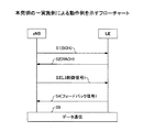
図7は本発明の一実施例による動作例を示すフローチャートである。図示の簡明化を図るため、無線リソースの割り当てに関する手順等は図示されていない。ステップS1で示されるように、基地局装置(eNB)からユーザ装置(UE)へ報知チャネル(BCH)が送信される。報知チャネルには、セル内で使用される様々なパラメータが含まれ、本実施例では特に周波数方向のプリコーディング解像度、CDDにおける遅延量に関する情報が報知チャネルに含まれている。 FIG. 7 is a flowchart showing an operation example according to an embodiment of the present invention. In order to simplify the illustration, the procedure related to radio resource allocation is not shown. As shown in step S1, a broadcast channel (BCH) is transmitted from the base station apparatus (eNB) to the user apparatus (UE). The broadcast channel includes various parameters used in the cell. In this embodiment, information on the precoding resolution in the frequency direction and the delay amount in CDD is included in the broadcast channel.
ステップS2ではユーザ装置が下り通信を要求する信号を送信する。図示の例ではRACHであるが、RACHに限定されず、何らかの通信を要求する信号でよい。 In step S2, the user apparatus transmits a signal requesting downlink communication. Although it is RACH in the illustrated example, the signal is not limited to RACH, and may be a signal requesting some kind of communication.
ステップS3では、上位レイヤ制御信号により、下り通信に使用される通信モードが何であるかが指定される。具体的には、そのユーザとの下り通信で行われるプリコーディングベクトルのフィードバック制御が、所定数個のリソースブロック毎に行われるか或いはシステム帯域の全リソースブロック共通に行われるかを示す情報、プリコーディングベクトルのフィードバック制御が全帯域共通になされる場合に、CDD方式が使用されるか否かを示す情報等が上位レイヤ制御信号に含まれる。 In step S3, the upper layer control signal specifies what communication mode is used for downlink communication. Specifically, information indicating whether feedback control of a precoding vector performed in downlink communication with the user is performed for every predetermined number of resource blocks or common to all resource blocks in the system band, When the feedback control of the coding vector is made common to all bands, information indicating whether or not the CDD scheme is used is included in the upper layer control signal.
図8は本実施例で用意されている3つの通信モードの相互関係を示す。通信モードは、基準モード、非CDDモード又はCDDモードである。 FIG. 8 shows the relationship between the three communication modes prepared in this embodiment. The communication mode is a reference mode, a non-CDD mode, or a CDD mode.
基準モードでは、プリコーディングベクトルのフィードバック制御が、システム帯域内の全リソースブロックに共通になされる。従ってフィードバック制御ループはストリーム数だけで済み、フィードバック制御負担は小さい。しかしながら周波数方向のフェージング変動が大きいようなチャネル状態にはふさわしくない。基準モードでは、CDD方式は使用されない。CDD方式を使用するか否かは、図中τ=0,τ≠0で表現されている。 In the reference mode, feedback control of the precoding vector is made common to all resource blocks in the system band. Therefore, the feedback control loop needs only the number of streams and the feedback control burden is small. However, it is not suitable for a channel state in which fading fluctuation in the frequency direction is large. In the reference mode, the CDD method is not used. Whether to use the CDD method is expressed by τ = 0 and τ ≠ 0 in the figure.
非CDDモードでは、プリコーディングベクトルのフィードバック制御が、システム帯域の区分けされた帯域毎に(例えば、例えばシステム帯域に25リソースブロック含まれていた場合に、5リソースブロック分の帯域毎に)行われる。従ってフィードバック制御ループは、(ストリーム数)×(全リソースブロック数÷所定数個)だけ必要になり、フィードバック制御負担は比較的多くなる。しかしながら、周波数方向のフェージング変動が大きいようなチャネル状態に適切に対応できる。 In the non-CDD mode, feedback control of the precoding vector is performed for each band obtained by dividing the system band (for example, for each band corresponding to 5 resource blocks when 25 resource blocks are included in the system band). . Therefore, the feedback control loop is required by (number of streams) × (total number of resource blocks ÷ predetermined number), and the feedback control burden becomes relatively large. However, it is possible to appropriately cope with a channel state in which fading fluctuation in the frequency direction is large.
CDDモードでは、基準モードと同様に、プリコーディングベクトルのフィードバック制御が、システム帯域内の全リソースブロックに共通になされる。CDDモードでは更にサイクリック遅延ダイバーシチが使用され、各アンテナに至る信号経路に何らかの遅延量τが設定される。 In the CDD mode, as in the reference mode, feedback control of the precoding vector is performed in common for all resource blocks in the system band. In the CDD mode, cyclic delay diversity is further used, and some amount of delay τ is set in the signal path to each antenna.
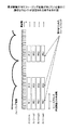
これらの通信モードは状況に応じて適宜切り替えられてよいが、本実施例では特に下りデータ量に応じて通信モードが使い分けられる。下りデータ量が比較的多い場合は、非CDDモードが使用される。従って非CDDモードは、例えば移動度が小さい場合に比較的多くのデータ通信をする場合に相応しい。非CDDモードでは、主にプリコーディングベクトルを周波数軸方向に5リソースブロック毎に細かく制御することで、伝送品質が向上するよう制御が行われる。これに対して、例えば音声パケットのように下りデータ量が比較的少ない場合は、基準モード又はCDDモードが使用される。見通しの悪い環境では例えば都市部ではマルチパスの遅延スプレッド自体が比較的大きいので、CDD方式は使用されず、基準モードが使用される。例えば見通しの良い環境では遅延スプレッドは比較的小さい。この場合、複数のパスを用いてダイバーシチを効果高め、信号品質を向上させるには、アンテナ毎の信号送信時刻が異なるようにCDDモードが使用される。基準モード又はCDDモードは、移動度が大きい場合や、音声パケットのようにデータ量が比較的少ない場合に相応しい。 These communication modes may be appropriately switched according to the situation, but in the present embodiment, the communication modes are selectively used according to the amount of downlink data. When the amount of downlink data is relatively large, the non-CDD mode is used. Therefore, the non-CDD mode is suitable for a case where a relatively large amount of data communication is performed, for example, when the mobility is small. In the non-CDD mode, control is performed so as to improve transmission quality mainly by finely controlling the precoding vector every 5 resource blocks in the frequency axis direction. On the other hand, for example, when the amount of downlink data is relatively small like a voice packet, the reference mode or the CDD mode is used. In an environment with poor visibility, for example, in urban areas, the multipath delay spread itself is relatively large, so the CDD method is not used and the reference mode is used. For example, the delay spread is relatively small in a good-looking environment. In this case, in order to improve diversity and improve signal quality using a plurality of paths, the CDD mode is used so that the signal transmission time differs for each antenna. The reference mode or CDD mode is suitable when the mobility is large or when the amount of data is relatively small such as a voice packet.
ところで、データ量が比較的少ない場合でも、周波数軸方向に5リソースブロック毎に細かくプリコーディングベクトルを制御することも理論上は考えられるかもしれない。しかしながら、プリコーディングベクトルの制御も、CDD方式における遅延量の制御も共に周波数領域での位相回転量の制御に帰着する。従って、双方の制御を行うかなり複雑な通信モードを敢えて用意する実益は乏しい。しかも、音声パケットのようなデータ量の少ない通信で、大きなフィードバック制御負担を強いることは、リソースの利用効率の観点からも得策ではない。従って図8で「×」印で示される通信モードは用意されていない。本実施例では、プリコーディングベクトルのフィードバック制御は、5リソースブロック毎に行われるか否かの2者択一であるが、更に多くの選択肢が用意されてもよい。例えば、3リソースブロック毎、5リソースブロック毎、全リソースブロック共通、のように「所定数個のリソースブロック毎」に関して3以上の選択肢が用意されてもよい。同様に、遅延量についても3以上の選択肢が用意されてもよい。 By the way, even if the amount of data is relatively small, it may theoretically be possible to control the precoding vector finely every 5 resource blocks in the frequency axis direction. However, both the control of the precoding vector and the control of the delay amount in the CDD method result in the control of the phase rotation amount in the frequency domain. Accordingly, there is little practical advantage of preparing a rather complicated communication mode for performing both controls. Moreover, forcing a large feedback control burden in communication with a small amount of data such as voice packets is not a good measure from the viewpoint of resource utilization efficiency. Accordingly, the communication mode indicated by “x” in FIG. 8 is not prepared. In this embodiment, the feedback control of the precoding vector is one of two choices of whether or not it is performed every 5 resource blocks, but more options may be prepared. For example, three or more options may be prepared for “every predetermined number of resource blocks” such as every 3 resource blocks, every 5 resource blocks, and all resource blocks. Similarly, three or more options may be prepared for the delay amount.
図7のステップS3では、基地局装置(eNB)はユーザ装置から通知された下り通信量に応じていずれかの通信モードを選択し、それをユーザ装置に通知する。これに応じてユーザ装置は、指示された通信モードでの下り通信を行う準備をする。 In step S3 in FIG. 7, the base station apparatus (eNB) selects one of the communication modes according to the downlink communication amount notified from the user apparatus, and notifies the user apparatus of it. In response to this, the user apparatus prepares to perform downlink communication in the instructed communication mode.
ステップS4では、ユーザ装置はプリコーディングベクトルのフィードバック信号を基地局装置に返す。 In step S4, the user apparatus returns a precoding vector feedback signal to the base station apparatus.
図9はユーザ装置から基地局装置へのフィードバック信号の内容を示す図である。[非CDDモード]の場合のフィードバック信号は、ユーザ装置は5リソースブロック毎に最適なプリコーディングベクトルと、そのプリコーディングベクトルが仮に使用された場合に予想されるストリーム毎のチャネル状態(例えば、CQI)とを含む。 FIG. 9 is a diagram illustrating the contents of a feedback signal from the user apparatus to the base station apparatus. The feedback signal in the case of [Non-CDD mode] indicates that the user apparatus has an optimum precoding vector for every five resource blocks and a channel state for each stream expected when the precoding vector is temporarily used (for example, CQI ).
[基準モード又はCDDモード]の場合、プリコーディングベクトルや遅延量が基地局装置から一意に指定されるか或いは選択肢で与えられるかによって、図中(A),(B),(C)に示されるようにフィードバック信号の内容が異なる。 In the case of [reference mode or CDD mode], it is shown in (A), (B), and (C) in the figure depending on whether the precoding vector and the delay amount are uniquely designated by the base station apparatus or given as an option. The content of the feedback signal is different.
(A)プリコーディングベクトル及び遅延量が、複数の選択肢で基地局装置からユーザ装置に通知されている場合、ユーザ装置はそれらの内最適な選択肢を決定する。最適なプリコーディングベクトルと、最適な遅延量(指示子で表現される)と、そのプリコーディングベクトル及び遅延量が仮に使用された場合に予想されるチャネル状態とがフィードバック信号に含まれる。チャネル状態は、全ストリームについての平均値で表現される。 (A) When the precoding vector and the delay amount are notified from the base station apparatus to the user apparatus by a plurality of options, the user apparatus determines an optimal option among them. The feedback signal includes an optimal precoding vector, an optimal delay amount (represented by an indicator), and a channel state expected when the precoding vector and the delay amount are temporarily used. The channel state is expressed as an average value for all streams.
(B)プリコーディングベクトルについては複数の選択肢で、遅延量については一意に基地局装置からユーザ装置に通知されている場合も、ユーザ装置はそれらの内最適な選択肢を決定する。最適なプリコーディングベクトルと、そのプリコーディングベクトル及び一意に指定された遅延量が仮に使用された場合に予想されるチャネル状態とがフィードバック信号に含まれる。このチャネル状態は、全ストリームについての平均値で表現される。 (B) Even when the precoding vector is a plurality of options and the delay amount is uniquely notified from the base station apparatus to the user apparatus, the user apparatus determines an optimal option among them. The feedback signal includes an optimal precoding vector and a channel state expected when the precoding vector and a uniquely specified delay amount are temporarily used. This channel state is expressed as an average value for all streams.
(C)プリコーディングベクトル及び遅延量が、基地局装置からユーザ装置に一意に通知されている場合、そのプリコーディングベクトル及び遅延量が仮に使用された場合に予想されるチャネル状態がフィードバック信号に含まれる。チャネル状態は、全ストリームについての平均値で表現される。 (C) When the precoding vector and the delay amount are uniquely notified from the base station apparatus to the user apparatus, a channel state expected when the precoding vector and the delay amount are temporarily used is included in the feedback signal. It is. The channel state is expressed as an average value for all streams.
図7のステップS5では、決定されたプリコーディングベクトル及び必要に応じて遅延量と共に下りデータ通信が行われる。以後、ユーザの希望する下り通信が変わったような場合には、その要求が基地局装置に通知され、通信モードの再決定等が行われてよい。 In step S5 of FIG. 7, downlink data communication is performed together with the determined precoding vector and the delay amount as necessary. Thereafter, when the downlink communication desired by the user changes, the request may be notified to the base station apparatus, and the communication mode may be re-determined.
502 各ユーザ毎の上りリンク信号の復調及び復号部
504 下りリンクスケジューラ
506リコーディング法選択部
508 ユーザデータチャネル生成部
510 プリコーディング部
512 周波数領域位相回転部
514 下りリンク(L1/L2)制御チャネル生成部
516 送信ダイバーシチ用変調部
520 共通パラメータ設定部
522 報知チャネル生成部
524 送信ダイバーシチ用変調部
526 直交リファレンス信号生成部
530 OFDM信号生成部
602 OFDM信号復調部
603 直交リファレンス信号レプリカ生成部
604 チャネル推定部
606 1/L2制御チャネル復調及び復号部
608 報知チャネル復調及び復号部
610 乗算部
612 データチャネル復調及び復号部
614 プリコーディングベクトル候補生成部
616 CDDに基づく周波数領域位相回転量生成部
618 推定部
620 上りリンクL1/L2制御チャネル生成部
622 上りリンクデータチャネル生成部
624 SC-FDMA変調部
502 Uplink signal demodulation and decoding section for each user 504
Claims (11)
下り通信を要求する1以上のユーザに割り当てるリソースを決定するスケジューリング手段と、
各ユーザ装置からのフィードバック信号に応じて、複数のアンテナに適用するプリコーディングベクトルを決定する手段と、
所定数のリソースブロック毎にプリコーディングベクトルのフィードバック制御を行うか否かを、各ユーザの要求する下りデータ量に応じてユーザ毎に決定する通信方式決定手段と、
スケジューリング手段で決定されたリソースで、前記複数のアンテナから下り信号を送信する手段と、
を有し、前記通信方式決定手段は、プリコーディングベクトルのフィードバック制御が、システム帯域中のリソースブロックに共通に行われる場合に、遅延ダイバーシチを下り通信に使用するか否かも決定する基地局装置。 A base station device used in a mobile communication system that supports multi-antenna communication using a precoding scheme and communication that performs delay diversity,
Scheduling means for determining resources to be allocated to one or more users requesting downlink communication;
Means for determining a precoding vector to be applied to a plurality of antennas according to a feedback signal from each user apparatus;
A communication scheme determining means for determining, for each user, whether or not to perform feedback control of a precoding vector for each predetermined number of resource blocks according to the amount of downlink data requested by each user;
Means for transmitting a downlink signal from the plurality of antennas with resources determined by a scheduling means;
And the communication scheme determining means also determines whether or not to use delay diversity for downlink communication when feedback control of precoding vectors is performed in common for resource blocks in the system band.
下り通信を要求する1以上のユーザに割り当てるリソースを基地局装置で決定するステップと、
各ユーザ装置からのフィードバック信号に応じて、基地局装置の複数のアンテナに適用するプリコーディングベクトルを決定するステップと、
スケジューリングで決定されたリソースで複数のアンテナから下り信号を送信するステップと、
を有し、所定数のリソースブロック毎にプリコーディングベクトルのフィードバック制御を行うか否かは、各ユーザの要求する下りデータ量に応じてユーザ毎に基地局装置で決定され、
プリコーディングベクトルのフィードバック制御がシステム帯域中のリソースブロックに共通に行われる場合に、遅延ダイバーシチを下り通信に使用するか否かも基地局装置で決定される方法。 A method used in a mobile communication system that supports multi-antenna communication using a precoding scheme and communication with delay diversity,
Determining a resource to be allocated to one or more users requesting downlink communication at the base station apparatus;
Determining a precoding vector to be applied to a plurality of antennas of the base station apparatus according to a feedback signal from each user apparatus;
Transmitting downlink signals from a plurality of antennas using resources determined by scheduling;
Whether to perform feedback control of the precoding vector for each predetermined number of resource blocks is determined by the base station apparatus for each user according to the amount of downlink data requested by each user,
A method in which the base station apparatus also determines whether or not to use delay diversity for downlink communication when feedback control of a precoding vector is performed in common for resource blocks in a system band.
Priority Applications (6)
| Application Number | Priority Date | Filing Date | Title |
|---|---|---|---|
| JP2007073726A JP4889532B2 (en) | 2007-03-20 | 2007-03-20 | Base station apparatus and method in mobile communication system |
| EP08722181A EP2129027A1 (en) | 2007-03-20 | 2008-03-14 | Base station device, user device, and method in mobile communication system |
| CN2008800164803A CN101682383B (en) | 2007-03-20 | 2008-03-14 | Base station device, user device, and method in mobile communication system |
| PCT/JP2008/054785 WO2008123028A1 (en) | 2007-03-20 | 2008-03-14 | Base station device, user device, and method in mobile communication system |
| KR1020097021198A KR20090119994A (en) | 2007-03-20 | 2008-03-14 | Base station device, user device, and method in mobile communication system |
| US12/531,673 US20100098009A1 (en) | 2007-03-20 | 2008-03-14 | Base station apparatus, user apparatus and method in mobile communication system |
Applications Claiming Priority (1)
| Application Number | Priority Date | Filing Date | Title |
|---|---|---|---|
| JP2007073726A JP4889532B2 (en) | 2007-03-20 | 2007-03-20 | Base station apparatus and method in mobile communication system |
Publications (2)
| Publication Number | Publication Date |
|---|---|
| JP2008236428A JP2008236428A (en) | 2008-10-02 |
| JP4889532B2 true JP4889532B2 (en) | 2012-03-07 |
Family
ID=39830530
Family Applications (1)
| Application Number | Title | Priority Date | Filing Date |
|---|---|---|---|
| JP2007073726A Expired - Fee Related JP4889532B2 (en) | 2007-03-20 | 2007-03-20 | Base station apparatus and method in mobile communication system |
Country Status (6)
| Country | Link |
|---|---|
| US (1) | US20100098009A1 (en) |
| EP (1) | EP2129027A1 (en) |
| JP (1) | JP4889532B2 (en) |
| KR (1) | KR20090119994A (en) |
| CN (1) | CN101682383B (en) |
| WO (1) | WO2008123028A1 (en) |
Families Citing this family (19)
| Publication number | Priority date | Publication date | Assignee | Title |
|---|---|---|---|---|
| EP2237458B1 (en) * | 2007-12-25 | 2018-08-08 | Sun Patent Trust | Wireless communication base station device, wireless communication mobile station device, and propagation path estimation method |
| ATE548811T1 (en) * | 2008-06-30 | 2012-03-15 | Alcatel Lucent | METHOD FOR ALLOCATING PRECODING VECTORS IN A MOBILE CELLULAR NETWORK |
| CN101729131B (en) * | 2008-11-03 | 2014-06-04 | 夏普株式会社 | Wireless communication system and pre-coding method |
| JP5103357B2 (en) * | 2008-11-04 | 2012-12-19 | 株式会社エヌ・ティ・ティ・ドコモ | Mobile terminal apparatus and radio base station apparatus |
| WO2010076854A1 (en) * | 2009-01-05 | 2010-07-08 | 富士通株式会社 | Communication device, mobile station, and communication control method |
| WO2010103989A1 (en) * | 2009-03-10 | 2010-09-16 | シャープ株式会社 | Wireless communication system, wireless transmitter, and control program for wireless transmitter |
| JP5387303B2 (en) | 2009-09-30 | 2014-01-15 | 富士通株式会社 | Reception device, communication system, and channel estimation method |
| CN102045722A (en) * | 2009-10-16 | 2011-05-04 | 大唐移动通信设备有限公司 | Method, system and device for carrying out physical layer regulation |
| WO2011161946A1 (en) * | 2010-06-21 | 2011-12-29 | パナソニック株式会社 | Terminal apparatus, base station apparatus, retransmission method and resource allocation method |
| WO2011162540A2 (en) * | 2010-06-22 | 2011-12-29 | 엘지전자 주식회사 | Method for transmitting response information to support plurality of component carriers in wireless communication system, and device therefor |
| CN103023543B (en) * | 2011-09-21 | 2015-07-01 | 中国移动通信集团设计院有限公司 | Beam forming method, apparatus and base station equipment |
| US9107214B2 (en) * | 2012-01-06 | 2015-08-11 | Industrial Technology Research Institute | Method of handling hybrid automatic repeat request acknowledgement responses in wireless communication system |
| US9137781B2 (en) | 2012-01-06 | 2015-09-15 | Industrial Technology Research Institute | Method of handling hybrid automatic repeat request resources in wireless communication system |
| US8908784B2 (en) * | 2012-01-30 | 2014-12-09 | Telefonaktiebolaget L M Ericsson (Publ) | Methods of communicating data including symbol mapping/demapping and related devices |
| US9660784B2 (en) * | 2012-03-14 | 2017-05-23 | Nokia Solutions And Networks Oy | Method and apparatus providing inter-transmission point phase relationship feedback for joint transmission CoMP |
| RU2735647C2 (en) * | 2016-02-29 | 2020-11-05 | Нтт Докомо, Инк. | User terminal, a radio base station and a radio communication method |
| US10404340B2 (en) * | 2016-10-11 | 2019-09-03 | Qualcomm Incorporated | Dynamic adjustment of transmission properties with continuous precoding |
| JP6558658B2 (en) * | 2018-03-08 | 2019-08-14 | サン パテント トラスト | Transmitter and receiver |
| JP7084553B2 (en) * | 2019-06-26 | 2022-06-14 | 株式会社日立国際電気 | Radio, communication system and communication method |
Family Cites Families (16)
| Publication number | Priority date | Publication date | Assignee | Title |
|---|---|---|---|---|
| CN100533999C (en) * | 2004-03-09 | 2009-08-26 | 汤姆森特许公司 | Mixed rake/equalizer receiver used for spread-spectrum system |
| JP4663369B2 (en) * | 2004-05-20 | 2011-04-06 | パナソニック株式会社 | Wireless communication system, wireless communication method, base station apparatus, and terminal apparatus |
| US7676007B1 (en) * | 2004-07-21 | 2010-03-09 | Jihoon Choi | System and method for interpolation based transmit beamforming for MIMO-OFDM with partial feedback |
| KR100938091B1 (en) * | 2004-10-13 | 2010-01-21 | 삼성전자주식회사 | Apparatus and method for providing efficient transmission using block coding and cyclic delay diversities in the OFDM based cellular systems |
| US7813306B2 (en) * | 2005-01-21 | 2010-10-12 | At&T Mobility Ii Llc | Method and apparatus for providing downlink delay diversity |
| AU2006283166A1 (en) * | 2005-08-22 | 2007-03-01 | Qualcomm Incorporated | Method and apparatus for selection of virtual antennas |
| JP2007073726A (en) | 2005-09-07 | 2007-03-22 | Matsushita Electric Ind Co Ltd | Semiconductor device and its manufacturing method |
| US8116267B2 (en) * | 2006-02-09 | 2012-02-14 | Samsung Electronics Co., Ltd. | Method and system for scheduling users based on user-determined ranks in a MIMO system |
| US10044532B2 (en) * | 2006-03-20 | 2018-08-07 | Texas Instruments Incorporated | Pre-coder selection based on resource block grouping |
| US8914015B2 (en) * | 2006-03-20 | 2014-12-16 | Qualcomm Incorporated | Grouping of users for MIMO transmission in a wireless communication system |
| WO2007133564A2 (en) * | 2006-05-09 | 2007-11-22 | Interdigital Technology Corporation | Codebook precoding with variable feedback |
| US20150030058A9 (en) * | 2006-05-17 | 2015-01-29 | Texas Instruments Inc. | Cqi feedback for mimo deployments |
| US7865153B2 (en) * | 2006-08-11 | 2011-01-04 | Samsung Electronics Co., Ltd. | Apparatus and method for transmit diversity and beamforming in a wireless network |
| KR20080026010A (en) * | 2006-09-19 | 2008-03-24 | 엘지전자 주식회사 | Data transmitting method using phase-shift based precoding and tranceiver implementing the same |
| US20080080635A1 (en) * | 2006-10-02 | 2008-04-03 | Nokia Corporation | Advanced feedback signaling for multi-antenna transmission systems |
| US8831116B2 (en) * | 2007-03-20 | 2014-09-09 | Motorola Mobility Llc | Method and apparatus for providing channel quality and precoding metric feedback in an orthogonal frequency division multiplexing communication system |
-
2007
- 2007-03-20 JP JP2007073726A patent/JP4889532B2/en not_active Expired - Fee Related
-
2008
- 2008-03-14 KR KR1020097021198A patent/KR20090119994A/en not_active Application Discontinuation
- 2008-03-14 EP EP08722181A patent/EP2129027A1/en not_active Withdrawn
- 2008-03-14 US US12/531,673 patent/US20100098009A1/en not_active Abandoned
- 2008-03-14 CN CN2008800164803A patent/CN101682383B/en not_active Expired - Fee Related
- 2008-03-14 WO PCT/JP2008/054785 patent/WO2008123028A1/en active Application Filing
Also Published As
| Publication number | Publication date |
|---|---|
| CN101682383A (en) | 2010-03-24 |
| CN101682383B (en) | 2013-12-25 |
| WO2008123028A1 (en) | 2008-10-16 |
| KR20090119994A (en) | 2009-11-23 |
| JP2008236428A (en) | 2008-10-02 |
| US20100098009A1 (en) | 2010-04-22 |
| EP2129027A1 (en) | 2009-12-02 |
Similar Documents
| Publication | Publication Date | Title |
|---|---|---|
| JP4889532B2 (en) | Base station apparatus and method in mobile communication system | |
| JP6208814B2 (en) | Method and apparatus for reporting channel state information in a wireless communication system | |
| JP5249322B2 (en) | Data transmission method in multi-antenna system | |
| JP4464836B2 (en) | Communication method for multi-antenna communication apparatus and multi-antenna communication apparatus | |
| JP5113239B2 (en) | Methods and configurations for communication networks | |
| US8488537B2 (en) | Method of transmitting channel information in multiple antenna system | |
| US8811506B2 (en) | Base station apparatus, user equipment, and communication control method in mobile communication system | |
| KR101433296B1 (en) | Feedback for supporting su-mimo and mu-mimo operation in wireless communication | |
| US9276783B2 (en) | Uplink transmission mode switching in single user multiple-input communication | |
| KR101769382B1 (en) | Method for reporting channel state information in wireless communication system and apparatus for same [technical field] | |
| US8902845B2 (en) | Communication control method, base station apparatus and mobile station apparatus | |
| US20090110114A1 (en) | Open-Loop MIMO Scheme and Signaling Support for Wireless Networks | |
| EP2219309B1 (en) | Transmitter, method for controlling transmission, and communication device | |
| WO2010032810A1 (en) | Base station apparatus, user equipment and precoding method | |
| EP2417780A1 (en) | Improved feedback strategies for multi-user mimo communication systems | |
| AU2011233860A1 (en) | Method and apparatus for controlling retransmission on uplink in a wireless communication system supporting MIMO | |
| US9059820B2 (en) | Method for transmitting channel quality information, user equipment, method for transmitting multi-user data, and base station | |
| EP2299751B1 (en) | Mobile station apparatus, communication system, and communication method | |
| JP4800447B2 (en) | Base station apparatus, transmission method, and mobile communication system | |
| JP5106501B2 (en) | Communication method for multi-antenna communication apparatus and multi-antenna communication apparatus |
Legal Events
| Date | Code | Title | Description |
|---|---|---|---|
| A621 | Written request for application examination |
Free format text: JAPANESE INTERMEDIATE CODE: A621 Effective date: 20090914 |
|
| A131 | Notification of reasons for refusal |
Free format text: JAPANESE INTERMEDIATE CODE: A131 Effective date: 20111004 |
|
| A521 | Written amendment |
Free format text: JAPANESE INTERMEDIATE CODE: A523 Effective date: 20111128 |
|
| TRDD | Decision of grant or rejection written | ||
| A01 | Written decision to grant a patent or to grant a registration (utility model) |
Free format text: JAPANESE INTERMEDIATE CODE: A01 Effective date: 20111213 |
|
| A01 | Written decision to grant a patent or to grant a registration (utility model) |
Free format text: JAPANESE INTERMEDIATE CODE: A01 |
|
| A61 | First payment of annual fees (during grant procedure) |
Free format text: JAPANESE INTERMEDIATE CODE: A61 Effective date: 20111213 |
|
| R150 | Certificate of patent or registration of utility model |
Ref document number: 4889532 Country of ref document: JP Free format text: JAPANESE INTERMEDIATE CODE: R150 Free format text: JAPANESE INTERMEDIATE CODE: R150 |
|
| FPAY | Renewal fee payment (event date is renewal date of database) |
Free format text: PAYMENT UNTIL: 20141222 Year of fee payment: 3 |
|
| R250 | Receipt of annual fees |
Free format text: JAPANESE INTERMEDIATE CODE: R250 |
|
| R250 | Receipt of annual fees |
Free format text: JAPANESE INTERMEDIATE CODE: R250 |
|
| R250 | Receipt of annual fees |
Free format text: JAPANESE INTERMEDIATE CODE: R250 |
|
| R250 | Receipt of annual fees |
Free format text: JAPANESE INTERMEDIATE CODE: R250 |
|
| LAPS | Cancellation because of no payment of annual fees |