JP5259498B2 - Driving tool - Google Patents
Driving tool Download PDFInfo
- Publication number
- JP5259498B2 JP5259498B2 JP2009134791A JP2009134791A JP5259498B2 JP 5259498 B2 JP5259498 B2 JP 5259498B2 JP 2009134791 A JP2009134791 A JP 2009134791A JP 2009134791 A JP2009134791 A JP 2009134791A JP 5259498 B2 JP5259498 B2 JP 5259498B2
- Authority
- JP
- Japan
- Prior art keywords
- idler
- spring
- switch
- force
- driving
- Prior art date
- Legal status (The legal status is an assumption and is not a legal conclusion. Google has not performed a legal analysis and makes no representation as to the accuracy of the status listed.)
- Expired - Fee Related
Links
- 239000000463 material Substances 0.000 claims description 18
- 238000002347 injection Methods 0.000 claims description 7
- 239000007924 injection Substances 0.000 claims description 7
- 230000001105 regulatory effect Effects 0.000 description 3
- 238000006073 displacement reaction Methods 0.000 description 2
- 230000007257 malfunction Effects 0.000 description 2
- 229920006311 Urethane elastomer Polymers 0.000 description 1
- 238000009825 accumulation Methods 0.000 description 1
- 238000002485 combustion reaction Methods 0.000 description 1
- 230000006835 compression Effects 0.000 description 1
- 238000007906 compression Methods 0.000 description 1
- 230000003116 impacting effect Effects 0.000 description 1
- 238000000034 method Methods 0.000 description 1
- 238000012986 modification Methods 0.000 description 1
- 230000004048 modification Effects 0.000 description 1
- 230000002093 peripheral effect Effects 0.000 description 1
- 230000002265 prevention Effects 0.000 description 1
Images


Landscapes
- Portable Nailing Machines And Staplers (AREA)
Description
この発明は、使用者が手に持って用いる例えば圧縮エア駆動式の釘打ち機等の打ち込み工具に関する。 The present invention relates to a driving tool such as a compressed air driven nail driver used by a user.
例えば、圧縮エア駆動式の打ち込み工具は、圧縮エアにより往復動するピストンを内装した本体部と、本体部の下部に突き出す状態に設けられて、ピストンに取り付けた打ち込み具打撃用のドライバが挿通される打ち込み通路を有する打ち込み部と、本体部の側部から側方へ延びるハンドル部と、打ち込み部の打ち込み通路内に1本ずつ供給される多数本の打ち込み具を装填できるマガジンを備えている。
ハンドル部の基部付近に設けたトリガ形式のスイッチレバーを指先で引き操作すると、トリガバルブと称される作動スイッチがオンして本体部のシリンダ上室に圧縮エアが供給されることによってピストンが下動する。ピストンが圧縮エアの推力によって下動すると、ドライバが打ち込み通路内を下動し、その下動途中で1本の打ち込み具が打撃されて射出口から打ち出される。
打ち込み部の先端には、誤動作防止用のコンタクトアームの先端部が配置されている。多くの場合、コンタクトアームの先端部は、打ち込み部の先端から一定寸法突き出す方向であって下動側にばね付勢されている。打ち込み作業において、コンタクトアームの先端部を被打ち込み材に押し付けてばね付勢力に抗して相対的に上動させると、スイッチレバーの引き操作が有効になって打ち込み動作がなされる。一方、コンタクトアームの被打ち込み材に対する押し付け操作がなされない結果、コンタクトアームが打ち込み部に対して相対的に上動操作されない状態ではスイッチレバーの引き操作は無効となって打ち込み動作がなされない。
このように従来打ち込み部の先端に設けたコンタクトアームの先端部を被打ち込み材に押し付けて相対的に上動させると打ち込み動作がなされ、被打ち込み材に対する押し付けがなされない結果、打ち込み部に対して一定寸法突き出された状態のままでは打ち込み動作がなされず、これにより誤操作が防止されるようになっている。
ところが、このストローク式の誤操作防止構造では、打ち込み動作のたびにコンタクトアームの先端部をばね付勢力に抗して被打ち込み材に押し付けて相対的に一定ストロークだけ上動させる必要があることから被打ち込み材に押圧痕(傷つき)ができる等の問題があった。従来、この問題を解消するためにいわゆるプッシュレス式のコンタクトアームを備えた打ち込み工具が提供されている。このプッシュレス式の打ち込み工具に関する技術が例えば下記の特許文献1に開示されている。
このプッシュレス式の打ち込み工具の場合、コンタクトアームはばねによってプッシュ式とは反対方向の上動側に付勢されている。このため、コンタクトアームの先端部は、常時には打ち込み部の先端(射出口)から突き出さずほぼ揃った状態となっている。このプッシュレス式の打ち込み工具の場合、射出口とともにコンタクトアームの先端部を被打ち込み材に軽く当接させた状態で、スイッチレバーを引き操作すると打ち込み動作がなされる。これに対して、コンタクトアームの先端部を被打ち込み材に当接させない状態で、スイッチレバーを引き操作すると、コンタクトアームがばね付勢力に抗して打ち込み部から突き出す方向に相対的に下動してスイッチレバーの引き操作が無効になる結果打ち込み動作がなされない。
このように、プッシュレス式のコンタクトアームの場合、その先端部を被打ち込み材に軽く当接させれば足りることから、前記プッシュ式の場合のような押圧痕の発生を大幅に低減して仕上がりの良い打ち込み作業を行うことができる。
For example, a compressed air drive type driving tool is provided in a state in which a piston that is reciprocated by compressed air is internally provided and protrudes to a lower portion of the main body, and a driver for hitting a driving tool attached to the piston is inserted therethrough. And a magazine that can be loaded with a plurality of driving tools supplied one by one into the driving path of the driving unit.
When a trigger-type switch lever provided near the base of the handle is pulled with a fingertip, an operation switch called a trigger valve is turned on, and compressed air is supplied to the cylinder upper chamber of the main unit to lower the piston. Move. When the piston is moved down by the thrust of the compressed air, the driver is moved down in the driving passage, and a single driving tool is hit and driven out from the injection port during the downward movement.
At the tip of the driving portion, the tip of a contact arm for preventing malfunction is disposed. In many cases, the distal end portion of the contact arm is spring-biased in the downward movement side in a direction protruding a certain dimension from the distal end of the driving portion. In the driving operation, when the tip of the contact arm is pressed against the driven material and moved up against the spring biasing force, the pulling operation of the switch lever becomes effective and the driving operation is performed. On the other hand, as a result of the pressing operation of the contact arm against the driven material not being performed, the pull operation of the switch lever is invalidated and the driving operation is not performed when the contact arm is not operated to move upward relative to the driving portion.
As described above, when the tip of the contact arm provided at the tip of the conventional driving portion is pressed against the driven material and moved relatively upward, the driving operation is performed, and the pressing against the driven material is not performed. The driving operation is not performed in a state in which the fixed dimension is protruded, thereby preventing an erroneous operation.
However, with this stroke-type erroneous operation prevention structure, it is necessary to press the tip of the contact arm against the material to be driven against the spring biasing force and move it upward by a relatively fixed stroke every time the driving operation is performed. There was a problem such as a pressing mark (scratched) on the driving material. Conventionally, in order to solve this problem, a driving tool having a so-called pushless contact arm has been provided. A technique related to this pushless driving tool is disclosed in, for example, Patent Document 1 below.
In the case of this pushless driving tool, the contact arm is urged by a spring to the upward movement side in the direction opposite to the push type. For this reason, the front-end | tip part of a contact arm is always in the state which did not protrude from the front-end | tip (injection port) of a driving | running | working part, and has been substantially aligned. In the case of this pushless driving tool, a driving operation is performed by pulling the switch lever in a state where the tip of the contact arm together with the injection port is in light contact with the driven material. On the other hand, if the switch lever is pulled while the tip of the contact arm is not in contact with the material to be driven, the contact arm moves downward in the direction protruding from the drive portion against the spring biasing force. As a result, the driving operation is not performed as a result of the switch lever pulling operation becoming invalid.
In this way, in the case of a pushless type contact arm, it is only necessary to make the tip end lightly abut against the material to be driven. It is possible to perform a good driving work.
しかしながら、上記従来のプッシュレス式の打ち込み工具の場合、次のような問題があった。従来は、コンタクトアームの上端部を、スイッチレバーに設けたアイドラに直接当接させてこのアイドラの動きを規制することによりスイッチレバーの引き操作を有効とする構成であったので、スイッチレバーの引き操作を無効とするために必要なアイドラの動きを一定以上確保する必要があり、その結果コンタクトアームのストロークを大きく確保する必要があり、この点でコンタクトアームの先端部付近の構成をコンパクト化しづらい問題があった。
本発明は、同じくプッシュレス式の打ち込み工具であって、スイッチレバーの引き操作を無効とする場合のコンタクトアームの必要ストロークを従来よりも大幅に小さくして、当該コンタクトアーム先端部付近の構成のコンパクト化を図りやすくすることを目的とする。
However, the conventional pushless driving tool has the following problems. Conventionally, the upper end of the contact arm is in direct contact with the idler provided on the switch lever to restrict the movement of the idler, thereby enabling the pulling operation of the switch lever. It is necessary to secure a certain amount of idler movement necessary to invalidate the operation, and as a result, it is necessary to secure a large stroke of the contact arm. In this respect, it is difficult to make the configuration near the tip of the contact arm compact. There was a problem.
The present invention is also a pushless type driving tool, in which the required stroke of the contact arm when the pulling operation of the switch lever is invalidated is significantly smaller than before, and the configuration near the tip of the contact arm is provided. The purpose is to facilitate downsizing.
このため、本発明は、特許請求の範囲の各請求項に記載した構成の打ち込み工具とした。
請求項1記載の打ち込み工具によれば、反打ち込み方向に付勢されたコンタクトアームの先端部を被打ち込み材に押し付けると、その上端部が第1ばねの付勢力P1に加えて押圧力Fにより第2アイドラに側方から押し付けられる。第2アイドラに対してコンタクトアームの上端部が付勢力P1と押圧力Fによって押し付けられることにより、その摩擦抵抗Rが第2アイドラの進退について移動抵抗として作用する。このため、第2アイドラは、第2ばねのばね付勢力P2とこの摩擦抵抗Rによって前進位置に固定される。
第2アイドラが前進位置に固定されることにより第3アイドラの前進が規制されて後退位置に固定される。第3アイドラが後退位置に固定された状態では第1アイドラの変位が規制されるため、スイッチレバーを引き操作すると、これとともに変位する第1アイドラによって作動スイッチのスイッチロッドが当該スイッチロッドをオフ位置に保持するオフ位置保持力P4に抗してオン位置に押し込まれて当該作動スイッチがオンし、従って本体部で打ち込み動作がなされる。このように、コンタクトアームを被打ち込み材に押し付けると、第2アイドラの後退抵抗が大きくなって当該第2アイドラが前進位置に固定され、これにより第3アイドラが後退位置に固定されてスイッチレバーの引き操作が有効となる。
これに対して、コンタクトアームの先端部を被打ち込み材に押し付けない状態では、コンタクトアームの上端部は、第1ばねの付勢力P1のみによって第2アイドラに押し付けられる。この状態では、第2アイドラの後退を規制するための摩擦抵抗Rが不足するため、スイッチレバーを引き操作すると、オフ位置保持力P4が勝るため第3アイドラが第3ばねに抗して前進し、従って第3アイドラの傾斜面に先端が当接された第2アイドラが第2ばねのばね付勢力P2と摩擦抵抗Rに抗して後退することにより作動スイッチのスイッチロッドがオフ位置に保持される。このため、作動スイッチはオンしないため、スイッチレバーの引き操作は無効になって打ち込み動作はなされない。
このようにコンタクトアームの先端部を被打ち込み材に押し付けた場合には、その上端部を第2ばねのばね付勢力P2と押圧力Fによって第2アイドラに押し付けて当該第2アイドラに対する摩擦抵抗Rを大きくすることにより第2アイドラの後退をロックしてスイッチレバーの引き操作を有効とする一方、当該先端部を被打ち込み材に押し付けない場合には、その上端部の第2アイドラに対する押し付け力を第1ばねのばね付勢力P1のみとして摩擦抵抗Rを小さくすることにより第2アイドラの後退を許容してスイッチレバーの引き操作を無効とする構成であるので、コンタクトアームのストロークを必要としない。第2アイドラに対する押圧力Fを発生させるか否かの範囲でコンタクアームを変位可能に設ければ足り、従来のような大きなストロークを必要とせず、実質的にストロークさせない構成であるので、射出口周辺のコンパクト化を図ることが容易になる。
請求項2記載の打ち込み工具によれば、第1〜第3ばねの各付勢力P1〜P3をオフ位置保持力P4に対して適切に設定することにより、コンタクトアームの上端部の第2アイドラに対する押圧力Fの有無によってスイッチレバーの引き操作の有効、無効を切り換えることができる。
For this reason, this invention was set as the driving tool of the structure described in each claim of a claim.
According to the driving tool of claim 1, when the tip of the contact arm biased in the counter driving direction is pressed against the driven material, the upper end of the contact arm is applied by the pressing force F in addition to the biasing force P1 of the first spring. It is pressed against the second idler from the side. When the upper end portion of the contact arm is pressed against the second idler by the urging force P1 and the pressing force F, the frictional resistance R acts as a movement resistance with respect to the advance and retreat of the second idler. For this reason, the second idler is fixed at the advanced position by the spring biasing force P2 of the second spring and the frictional resistance R.
When the second idler is fixed at the forward movement position, the forward movement of the third idler is restricted and fixed at the backward movement position. When the third idler is fixed at the retracted position, the displacement of the first idler is restricted. Therefore, when the switch lever is pulled, the switch rod of the operating switch is moved to the off position by the first idler that is displaced along with the switch lever. The operation switch is turned on by being pushed into the on position against the off-position holding force P4 held in the position, so that the driving operation is performed in the main body. As described above, when the contact arm is pressed against the driven material, the retraction resistance of the second idler is increased and the second idler is fixed at the forward movement position, whereby the third idler is fixed at the reverse movement position and the switch lever The pull operation becomes effective.
On the other hand, in a state where the tip end portion of the contact arm is not pressed against the driven material, the upper end portion of the contact arm is pressed against the second idler only by the urging force P1 of the first spring. In this state, since the frictional resistance R for restricting the backward movement of the second idler is insufficient, when the switch lever is pulled, the off-position holding force P4 is won and the third idler moves forward against the third spring. Accordingly, the second idler whose tip is in contact with the inclined surface of the third idler moves backward against the spring biasing force P2 of the second spring and the frictional resistance R, so that the switch rod of the operation switch is held in the off position. The For this reason, since the operation switch is not turned on, the pulling operation of the switch lever is invalid and no driving operation is performed.
When the tip of the contact arm is pressed against the driven material in this way, the upper end of the contact arm is pressed against the second idler by the spring biasing force P2 and the pressing force F of the second spring, and the frictional resistance R against the second idler. By enlarging the value, the backward movement of the second idler is locked to make the switch lever pulling operation effective. On the other hand, when the tip is not pressed against the driven material, the pressing force of the upper end against the second idler is increased. Since the friction resistance R is reduced only by the spring biasing force P1 of the first spring, the second idler is allowed to retreat and the switch lever pulling operation is invalidated, so that the contact arm stroke is not required. Since it is sufficient that the contact arm is displaceable within the range of whether or not the pressing force F against the second idler is generated, it does not require a large stroke as in the prior art and does not substantially make a stroke. It becomes easy to make the periphery compact.
According to the driving tool of
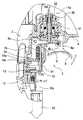
次に、本発明の実施形態を図1〜図4に基づいて説明する。図1は、本実施形態に係る打ち込み工具1の全体を示している。図示するように打ち込み工具1は、その打ち込み方向(打ち込み具が打ち出される方向)を下向きとする姿勢で示されている。以下の説明では、部材及び構成等の上下方向について特に断らない限り打ち込み方向を下方、その反対方向を上方とし、打ち込み方向に沿った方向を単に上下方向ともいう。
本実施形態の打ち込み工具1は、圧縮エア駆動式の釘打ち機で、ピストン9を内装した本体部2と、本体部2の下部から下方へ突き出す状態に設けられた打ち込み部3と、本体部2の側部から側方へ長く延びるハンドル部4と、ハンドル部4の先端部付近と打ち込み部3との間に掛け渡し状態で取り付けたマガジン5を備えている。マガジン5は、多数本の打ち込み具を連結帯で並列に結合した連結打ち込み具を巻き回状態で収容する形態のものが例示されている。
使用者が把持するハンドル部4の基部付近には、スイッチレバー6とトリガバルブと称される作動スイッチ20が配置されている。使用者がこのスイッチレバー6を引き操作すると、作動スイッチ20がオンして本体部2での打ち込み動作がなされる。
本実施形態に係る打ち込み工具1は、使用者によるスイッチレバー6の引き操作の有効、無効を切り換えて本体部2での不用意な打ち込み動作を回避するための動作制御機構Cについて特徴を有するものであり、その他の本体部2等の打ち込み工具1としての基本的な構成については特に変更を要しないので簡単に説明する。
ハンドル部4内の蓄圧室4aに供給された圧縮エアが作動スイッチ20のオン操作によって本体部2に供給される。ピストン9の上室に圧縮エアが供給されると、ピストン9が下動する。ピストン9の下面には下方へ延びる打ち込み具打撃用の打撃ドライバ7が取り付けられている。ピストン9が下動するとこの打撃ドライバ7が打ち込み部3の打ち込み通路内3aを下動する。打ち込み通路3a内には、マガジン5から打ち込み具が1本ずつ供給される。打ち込み通路3a内に供給された1本の打ち込み具が打撃ドライバ7で打撃されて、射出口3bから打ち出される。図では打ち込み具の図示が省略されている。
スイッチレバー6の引き操作を解除すると、ピストン上室が排気される一方、ピストン下室にリターンエアが供給されることによりピストン9が上死点に戻される。ピストン9が上死点に戻されると打撃ドライバ7が打ち込み通路3a内を上方へ退避されるとともに、次の打ち込み具が供給される。
Next, an embodiment of the present invention will be described with reference to FIGS. FIG. 1 shows the entire driving tool 1 according to the present embodiment. As shown in the drawing, the driving tool 1 is shown in a posture in which the driving direction (direction in which the driving tool is driven out) is downward. In the following description, unless otherwise specified, the driving direction is downward, the opposite direction is upward, and the direction along the driving direction is also simply referred to as the vertical direction.
The driving tool 1 of the present embodiment is a compressed air drive type nailing machine, and includes a
A
The driving tool 1 according to the present embodiment is characterized by an operation control mechanism C for switching between enabling and disabling of the pulling operation of the
The compressed air supplied to the
When the pulling operation of the
スイッチレバー6の引き操作は、動作制御機構Cによってその有効、無効が切り換えられて、不用意な引き操作による本体部2の誤動作が未然に回避されるようになっている。この動作制御機構Cは、コンタクトアーム10を備えている。コンタクトアーム10は、この先端部10aと延長部10bと突き当て部10cを備えている。コンタクトアーム10は、概ね打ち込み部3に沿って配置され、その全体として上下に変位可能に支持されている。
打ち込み部3の先端には、コンタクトアーム10の先端部10aが配置されている。先端部10aは円環形状を有しており、打ち込み部3をその内周側に位置させた状態に配置されている。この先端部10aは、打ち込み部3の先端から僅かに突き出している。この先端部10aから延長部10bが一体に設けられている。延長部10bは屈曲しながら上方へ延びており、その上端部に突き当て部10cが一体に設けられている。この突き当て部10cは、スイッチレバー6の下方に位置している。コンタクトアーム10、スイッチレバー6及びその周辺を含む動作制御機構Cの詳細が図2以下に示されている。
スイッチレバー6は支軸6aを介して上下に傾動操作可能な状態で本体部2の側部に支持されている。スイッチレバー6の下面に使用者が指をあてがって、上方へ引き操作する。スイッチレバー6の背面(上面)には、第1アイドラ8が支持されている。この第1アイドラ8は、支軸8aを介して上下に傾動可能な状態で支持されている。この第1アイドラ8に対して上方から作動スイッチ20のスイッチロッド21が当接されている。作動スイッチ20は、従来公知のもので本実施形態において特に変更を要しないので詳細な説明は省略する。スイッチロッド21はオフ位置保持力P4(第4ばね22の付勢力と蓄圧室4aのエア圧の合計力)によって下方のオフ位置(図2に示す位置)に突き出す方向に付勢されている。スイッチレバー6の引き操作によりスイッチロッド21がオフ位置保持力P4に抗して上方のオン位置(図3に示す位置)に押し込まれると当該作動スイッチ20がオンする。作動スイッチ20がオンすると、ハンドル部4内の蓄圧室4aから本体部2のピストン上室に圧縮エアが供給されて本体部2で打ち込み動作がなされる。
前記コンタクトアーム10は第1ばね11によって上方へ付勢されている。第1ばね11は、突き当て部10cと本体部2との間に介装されている。突き当て部10cは、第2アイドラ12に突き当てられている。突き当て部10cが第2アイドラ12に側方から突き当てられることによりコンタクトアーム10の上動端位置が規制されている。このため、コンタクトアーム10の突き当て部10cは、少なくとも第一ばね11の付勢力P1によって第2アイドラ12に突き当てられている。このようにコンタクトアーム10は、少なくとも第1ばね11の付勢力によってその突き当て部10cが第2アイドラ12に下方から突き当てられているため、当該打ち込み工具1の使用時にその機能を果たすにあたって実質的に上下動しない。
The pulling operation of the
A
The
The
第2アイドラ12は、コンタクトアーム10の付勢方向に対して交差する方向(本実施形態では直交する方向、図において左右方向)に進退可能な状態で本体部2に支持されている。第2アイドラ12は、第2ばね13の付勢力P2によって前進方向(図において右方)に付勢されている。第2アイドラ12の先端部(図において右端部)は、第3アイドラ14に突き当てられている。第3アイドラ14は上下に進退可能な状態で本体部2に支持されている。第3アイドラ14の下部には、傾斜面14aが設けられている。この傾斜面14aは、進退方向に対して30°の傾斜角度で設けられている。この傾斜面14aに第2アイドラ12の先端部が当接されている。第2アイドラ12の先端部も、この傾斜面14aに合わせて傾斜面に形成されている。この傾斜面相互の摺接作用により、第2アイドラ12が後退が許容された状態では第3アイドラ14の下方への前進が許容され、第2アイドラ12の後退が規制された状態では第3アイドラ14の前進も規制された状態となる。
第3アイドラ14は、第3ばね15の付勢力P3によって後退方向に付勢されている。第3ばね15は、本体部2の側部に張り出して設けたストッパ壁部2aと、第3アイドラ14の上端部との間に介装されている。この第3ばね15の付勢力P3によって第3アイドラ14は、その上端部を第1アイドラ8の傾動先端側に下方から突き当てる方向に付勢されている。第3アイドラ14の後退端は、本体部2のストッパ壁部2aに、傾斜面14aの上部に設けた段差部14bが当接することにより規制される。なお、第3アイドラ14の後退端は、その上端部が第1アイドラ8に突き当てられることによっても規制される。又、前記したように第1アイドラ8には、スイッチロッド21がオフ位置保持力P4で常時上方から突き当てられている。
第3アイドラ14の前進が規制された状態では、第1アイドラ8の傾動先端側の下方への変位が規制された状態となる。このため、図3に示すようにスイッチレバー6を引き操作すると第1アイドラ8が傾動先端側を支点として上方へ変位し、その結果スイッチロッド21がオフ位置保持力P4に抗して上方へ十分なストロークだけ押し込まれることにより作動スイッチ20がオンする。
逆に、第3アイドラ14が第3ばね15の付勢力P3に抗して下方へ前進すると、第1アイドラ8の傾動先端側が下方へ変位する。このため、図4に示すようにスイッチレバー6を引き操作しても第1アイドラ8はスイッチロッド21の突き当て部を支点として傾動する結果、第1アイドラ8の上方へのストロークが不足し、従ってスイッチロッド21がオン位置側に十分に押し込まれないために作動スイッチ20はオンしない。
The
The
In a state where the forward movement of the
Conversely, when the
このように、第3アイドラ14の前進が規制された状態であることがスイッチレバー6の引き操作が有効となる条件となっている。前記したように第3アイドラ14が第3ばね15のばね付勢力P3に抗して前進するためには、第2アイドラ12が後退する必要がある。第2アイドラ12は、第2ばね13の付勢力P2によって前進方向に付勢されている。又、第2アイドラ12にはコンタクトアーム10の突き当て部10cが側方から直交方向に少なくとも第1ばね11の付勢力P1で押し付けられている。このため、第2アイドラ12の後退動作について、第1ばね11のばね付勢力P1で押し付けられた突き当て部10cが摩擦抵抗RP1となって作用する。なお、摩擦抵抗Rの添え字「P1」は、ばね付勢力P1による摩擦抵抗の意味で用いる。
従って、第2アイドラ12は、第2ばね13の付勢力P2と突き当て部10cの摩擦抵抗RP1とを上回る後退方向の外力が付加されると後退し、その結果スイッチレバー6の引き操作が無効となる。第2アイドラ12には、スイッチレバー6を引き操作した際に第3アイドラ14を経て間接的に付加される作動スイッチ20のオフ位置保持力P4が当該第2アイドラ12を後退させるための外力として作用する。
第3アイドラ14の傾斜面14aは、その進退方向に対して30°の傾斜角度で形成されている。このため、第3アイドラ14に付加される前進方向の外力の一部が第2アイドラ12を後退させるための外力として作用する。第3アイドラ14には、スイッチロッド21に作用するオフ位置保持力P4から第3ばね15のばね付勢力P3を差し引いた力が前進させるための付勢力として作用し、さらにその一部が傾斜面14aを経て第2アイドラ12を後退させるための外力として作用する。
このため、コンタクトアーム10の先端部10aを被打ち込み材Wに押し付けない状態であって、第2アイドラ12に対する摩擦抵抗Rとして第1ばね11の付勢力P1のみが作用している状態では、スイッチレバー6を引き操作すると、図4に示すように第2アイドラ12が第2ばね13のばね付勢力P2と摩擦抵抗Rに抗して後退し、第3アイドラ14が第3ばね15のばね付勢力P3に抗して前進する結果、第1アイドラ8がその傾動先端側を下方へ変位させるため、作動スイッチ20のスイッチロッド21はオフ位置保持力P4により下方のオフ位置に保持されて当該スイッチレバー6の引き操作は無効となる。
Thus, the condition in which the forward movement of the
Therefore, the
The
For this reason, in a state where the
これに対して、打ち込み部3の先端を被打ち込み材Wに押し付けると、コンタクトアーム10の先端部10aが射出口3bから僅かに突き出されているため、当該先端部10aが直接被打ち込み材Wに押し付けられる。コンタクトアーム10の先端部10aを被打ち込み材Wに押し付けた状態では、その押圧力Fが第1ばね11のばね付勢力P1に加わって第2アイドラ12に摩擦抵抗RP1+Fとして付加される。この場合、押圧力Fは、使用者の押し付け力に相当する。なお、摩擦抵抗Rの添え字「P1+F」は、ばね付勢力P1と押圧力Fによる摩擦抵抗の意味で用いる。
RP1+F>RP1であることから、コンタクトアーム10の先端部10aを被打ち込み材Wに押圧力Fで押し付けた状態では、第2アイドラ12が、第2ばね13のばね付勢力P2と摩擦抵抗RP1+Fとの合計外力によってその後退動作が規制されてその前進位置にロックされた状態となる。第2アイドラ12が前進位置にロックされるため、第3アイドラ14の前進動作が規制されて当該第3アイドラ14が後退位置にロックされる。第3アイドラ14が後退位置にロックされるため、第1アイドラ8の傾動先端部が下方へ変位不能にロックされる。このため、図3に示すようにスイッチレバー6を引き操作すると、第1アイドラ8が支軸8aを中心とする傾動先端部を支点として上方(図において反時計回り方向)へ傾動する。その結果、作動スイッチ20のスイッチロッド21が第1アイドラ8によってオフ位置保持力P4に抗して上方のオン位置に押し込まれて当該作動スイッチ20がオンし、従って本体部2で打ち込み動作が開始される。
On the other hand, when the tip of the driving
Since R P1 + F > R P1 , in a state where the
以上説明したように本実施形態の打ち込み工具1によれば、コンタクトアーム10の先端部10aを被打ち込み材Wに押し付けることにより発生する突き当て部10cの押圧力Fの有無を条件に、スイッチレバー6の引き操作の有効、無効を切り換える構成であるので、コンタクトアーム10の押し付けに伴うストロークを実質的に必要としない。このため、コンタクトアーム10の支持構造を簡略化して、射出口3b周辺の構成を一層コンパクト化することが容易になる。
また、例示した動作制御機構Cによれば、コンタクトアーム10の先端部10aを被打ち込み材Wに押し付けることにより発生する押圧力Fを利用してスイッチレバー6の引き操作の有効無効を切り換える構成であり、実質的にコンタクトアーム10をストロークさせることなく切り換える構成であるので、いわゆる連続打ちを行う場合であっても打ち込み動作ごとに当該打ち込み工具1を被打ち込み材Wから離す必要がないことから、当該打ち込み工具1を横方向にずらせて行ういわゆる引きずり打ちを楽に行うことができるようになる。
以上説明した実施形態には、種々変更を加えることができる。例えば、第1ばね11、第2ばね13、第3ばね15については、例示したように圧縮コイルばねを用いる構成の他、引っ張りばねあるいはエアダンパー、ウレタンゴム等のその他の付勢手段を用いる構成としてもよい。
また、例示した動作制御機構Cは、例示したエア駆動式の釘打ち機、タッカ、あるいはガス燃焼式の釘打ち機等、さらには電動式タッカ等その他の打ち込み工具に広く適用することができる。電動式の打ち込み工具の場合には、例示したトリガバルブと称される作動スイッチ20に代えてマイクロスイッチと称される作動スイッチが用いられ、このマイクロスイッチのオフ位置側にばね付勢されたスイッチノブがスイッチロッド21に相当することから、例示した動作制御機構Cを同様に適用することができる。
As described above, according to the driving tool 1 of the present embodiment, the switch lever is subject to the presence or absence of the pressing force F of the abutting
In addition, according to the illustrated operation control mechanism C, the configuration is such that the validity of the pulling operation of the
Various modifications can be made to the embodiment described above. For example, for the
The illustrated operation control mechanism C can be widely applied to other driving tools such as the illustrated air-driven nailing machine, tacker, gas combustion type nailing machine, and further an electric tacker. In the case of an electric driving tool, an operation switch called a micro switch is used instead of the
W…被打ち込み材
1…打ち込み工具
2…本体部
3…打ち込み部
4…ハンドル部、4a…蓄圧室
5…マガジン
6…スイッチレバー、6a…支軸
7…打撃ドライバ
8…第1アイドラ、8a…支軸
9…ピストン
C…動作制御機構
10…コンタクトアーム
10a…先端部、10b…延長部、10c…突き当て部
11…第1ばね
P1…第1ばねの付勢力
12…第2アイドラ
13…第2ばね
P2…第2ばねの付勢力
14…第3アイドラ
15…第3ばね
P3…第3ばねの付勢力
20…作動スイッチ(トリガバルブ)
21…スイッチロッド
22…第4ばね
P4…オフ位置保持力(第4ばねの付勢力+エア圧)
R…コンタクトアームの第2アイドラに対する摩擦抵抗
F…コンタクトアームの被打ち込み材に対する押圧力
W ... Material to be driven 1 ... Driving
21 ...
R: Friction resistance of contact arm against second idler F: Pressing force of contact arm against workpiece
Claims (2)
先端部を前記本体部の射出口から打ち込み方向に僅かに突き出させた押圧位置に位置させ、かつ第1ばねにより反打ち込み方向にばね付勢されたコンタクトアームを備え、
該コンタクトアームの上端部と前記スイッチレバーに設けた第1アイドラとの間に、前記第1ばねの付勢方向に交差する方向に進退可能に設けられて、前記コンタクトアームの上端部が前記第1ばねの付勢力P1により側方から押圧される第2アイドラと、該第2アイドラの進退方向に交差する方向に進退可能に設けられて一端側に設けた傾斜面に前記第2アイドラが当接され、他端側が前記第1アイドラに当接された第3アイドラを備え、
前記第2アイドラは付勢力P2の第2ばねにより前記第3アイドラの傾斜面に当接する前進方向にばね付勢され、前記第3アイドラは付勢力P3の第3ばねにより前記第1アイドラに当接する後退方向にばね付勢され、前記作動スイッチのスイッチロッドがオフ位置保持力P4によりオフ位置に保持されており、
前記コンタクトアームの先端部を前記被打ち込み材に押圧した状態では、該押圧力Fと前記第1ばねのばね付勢力P1による摩擦抵抗Rと前記第2ばねのばね付勢力P2により該第2アイドラの該第2ばねに抗した後退動作が規制されて、前記第3アイドラの第3ばねに抗した前進動作が規制されることにより、前記第1アイドラにより前記作動スイッチのスイッチロッドが前記オフ位置保持力P4に抗してオン位置に押し込まれて前記スイッチレバーの引き操作が有効とされる一方、前記コンタクトアームの先端部を前記被打ち込み材に押圧しない状態では、前記押圧力Fが不足する結果前記摩擦抵抗Rが小さくなることにより、該第2アイドラが該摩擦抵抗Rと前記第2ばねの付勢力P2に抗して後退し、かつ前記第3アイドラが第3ばねの付勢力P3に抗して前進して、前記作動スイッチのスイッチロッドが前記オフ位置保持力P4によりオフ位置に保持されて前記スイッチレバーの引き操作が無効とされる構成とした打ち込み工具。 A driving tool for driving the main body when the switch rod of the operation switch is moved to the ON position by pulling the switch lever,
A contact arm that is positioned at a pressing position in which the tip is slightly protruded from the injection port of the main body in the driving direction and is biased in the counter driving direction by the first spring;
The upper end of the contact arm is provided between the upper end of the contact arm and a first idler provided on the switch lever so as to be able to advance and retreat in a direction intersecting the urging direction of the first spring. A second idler pressed from the side by the urging force P1 of one spring, and the second idler is applied to an inclined surface provided on one end side so as to be able to advance and retreat in a direction intersecting the advancing and retreating direction of the second idler. A third idler in contact with the first idler on the other end side,
The second idler is spring-biased in a forward direction in contact with the inclined surface of the third idler by a second spring having a biasing force P2, and the third idler is abutted against the first idler by a third spring having a biasing force P3. The switch rod of the operation switch is held in the off position by the off position holding force P4, and is spring-biased in the retreating direction in contact therewith,
In a state where the tip of the contact arm is pressed against the driven material, the second idler is caused by the pressing force F, the frictional resistance R due to the spring biasing force P1 of the first spring, and the spring biasing force P2 of the second spring. The backward movement against the second spring of the third idler is restricted, and the forward movement against the third spring of the third idler is restricted, so that the switch rod of the operation switch is turned off by the first idler. The switch lever is pushed against the holding force P4 to enable the pulling operation of the switch lever. On the other hand, when the tip of the contact arm is not pressed against the driven material, the pressing force F is insufficient. As a result, when the frictional resistance R becomes smaller, the second idler moves backward against the frictional resistance R and the urging force P2 of the second spring, and the third idler Advances against the biasing force P3, driving the switch rod of the actuating switch is configured to the pulling operation of the switch lever is held in the off position is invalidated by the off position retaining force P4 tool.
2. The driving tool according to claim 1, wherein an off-position holding force P < b > 4 of the operation switch is a frictional resistance R P1 + F caused by the pressing force F and a biasing force P < b > 1 of the first spring, and an attachment of the second spring. The frictional resistance R P1 due to the biasing force P1 of the first spring, the biasing force P2 of the second spring, and the biasing force of the third spring is smaller than the sum of the biasing force P2 and the biasing force P3 of the third spring. Driving tool set larger than the sum of P3.
Priority Applications (1)
| Application Number | Priority Date | Filing Date | Title |
|---|---|---|---|
| JP2009134791A JP5259498B2 (en) | 2009-06-04 | 2009-06-04 | Driving tool |
Applications Claiming Priority (1)
| Application Number | Priority Date | Filing Date | Title |
|---|---|---|---|
| JP2009134791A JP5259498B2 (en) | 2009-06-04 | 2009-06-04 | Driving tool |
Publications (2)
| Publication Number | Publication Date |
|---|---|
| JP2010280030A JP2010280030A (en) | 2010-12-16 |
| JP5259498B2 true JP5259498B2 (en) | 2013-08-07 |
Family
ID=43537254
Family Applications (1)
| Application Number | Title | Priority Date | Filing Date |
|---|---|---|---|
| JP2009134791A Expired - Fee Related JP5259498B2 (en) | 2009-06-04 | 2009-06-04 | Driving tool |
Country Status (1)
| Country | Link |
|---|---|
| JP (1) | JP5259498B2 (en) |
Family Cites Families (2)
| Publication number | Priority date | Publication date | Assignee | Title |
|---|---|---|---|---|
| JPH0753907Y2 (en) * | 1991-12-27 | 1995-12-13 | マックス株式会社 | Nailer safety device |
| JP4964624B2 (en) * | 2007-03-06 | 2012-07-04 | 株式会社マキタ | Driving machine |
-
2009
- 2009-06-04 JP JP2009134791A patent/JP5259498B2/en not_active Expired - Fee Related
Also Published As
| Publication number | Publication date |
|---|---|
| JP2010280030A (en) | 2010-12-16 |
Similar Documents
| Publication | Publication Date | Title |
|---|---|---|
| JP6408944B2 (en) | Driving tool | |
| JP2011088269A (en) | Driving tool | |
| EP1795305B1 (en) | Idle driving operation preventing devices for fastener driving tools, and fastener driving tools having such devices | |
| JP2018144122A (en) | Driving tool | |
| CN101378883A (en) | Nailer | |
| JP4964624B2 (en) | Driving machine | |
| JP5589804B2 (en) | Driving machine | |
| JP5259498B2 (en) | Driving tool | |
| JP5286939B2 (en) | Driving machine | |
| JP5855518B2 (en) | Driving tool | |
| US20120187617A1 (en) | Finger pinch preventing hand-held quick-clamping device | |
| JP2019521865A (en) | Air nailer with single and contact trigger | |
| US7070081B2 (en) | Driver guides for use with fastener-driving tools and fastener-driving tools having such driver guides | |
| CN101172337A (en) | Driving depth adjustment device for driving machine | |
| JP3794276B2 (en) | Nailer | |
| JP5055817B2 (en) | Contact mechanism in driving tools | |
| JP3825866B2 (en) | Trigger device for fixing tool driving machine | |
| JP4992199B2 (en) | Driving tool contact mechanism | |
| JP4877464B2 (en) | Offset structure in contact of driving tool | |
| JP2011115903A (en) | Driving machine | |
| JP3670182B2 (en) | Driving machine | |
| JP2010023174A (en) | Driving machine for staples | |
| JP5645071B2 (en) | Driving machine | |
| JP5201402B2 (en) | Driving machine | |
| EP2835225A1 (en) | Fastener feeding device for a driving tool |
Legal Events
| Date | Code | Title | Description |
|---|---|---|---|
| A621 | Written request for application examination |
Free format text: JAPANESE INTERMEDIATE CODE: A621 Effective date: 20111130 |
|
| A977 | Report on retrieval |
Free format text: JAPANESE INTERMEDIATE CODE: A971007 Effective date: 20130409 |
|
| TRDD | Decision of grant or rejection written | ||
| A01 | Written decision to grant a patent or to grant a registration (utility model) |
Free format text: JAPANESE INTERMEDIATE CODE: A01 Effective date: 20130416 |
|
| A61 | First payment of annual fees (during grant procedure) |
Free format text: JAPANESE INTERMEDIATE CODE: A61 Effective date: 20130424 |
|
| FPAY | Renewal fee payment (event date is renewal date of database) |
Free format text: PAYMENT UNTIL: 20160502 Year of fee payment: 3 |
|
| R150 | Certificate of patent or registration of utility model |
Free format text: JAPANESE INTERMEDIATE CODE: R150 Ref document number: 5259498 Country of ref document: JP Free format text: JAPANESE INTERMEDIATE CODE: R150 |
|
| R250 | Receipt of annual fees |
Free format text: JAPANESE INTERMEDIATE CODE: R250 |
|
| R250 | Receipt of annual fees |
Free format text: JAPANESE INTERMEDIATE CODE: R250 |
|
| R250 | Receipt of annual fees |
Free format text: JAPANESE INTERMEDIATE CODE: R250 |
|
| R250 | Receipt of annual fees |
Free format text: JAPANESE INTERMEDIATE CODE: R250 |
|
| R250 | Receipt of annual fees |
Free format text: JAPANESE INTERMEDIATE CODE: R250 |
|
| R250 | Receipt of annual fees |
Free format text: JAPANESE INTERMEDIATE CODE: R250 |
|
| R250 | Receipt of annual fees |
Free format text: JAPANESE INTERMEDIATE CODE: R250 |
|
| LAPS | Cancellation because of no payment of annual fees |