JP5259441B2 - Drum washing machine - Google Patents

Drum washing machine Download PDF

Info

Publication number
JP5259441B2
JP5259441B2 JP2009019738A JP2009019738A JP5259441B2 JP 5259441 B2 JP5259441 B2 JP 5259441B2 JP 2009019738 A JP2009019738 A JP 2009019738A JP 2009019738 A JP2009019738 A JP 2009019738A JP 5259441 B2 JP5259441 B2 JP 5259441B2
Authority
JP
Japan
Prior art keywords
water
foam
drum
washing
circulation
Prior art date
Legal status (The legal status is an assumption and is not a legal conclusion. Google has not performed a legal analysis and makes no representation as to the accuracy of the status listed.)
Expired - Fee Related
Application number
JP2009019738A
Other languages
Japanese (ja)
Other versions
JP2010172547A (en
Inventor
智 西脇
Current Assignee (The listed assignees may be inaccurate. Google has not performed a legal analysis and makes no representation or warranty as to the accuracy of the list.)
Toshiba Corp
Toshiba Lifestyle Products and Services Corp
Original Assignee
Toshiba Corp
Toshiba Consumer Electronics Holdings Corp
Toshiba Home Appliances Corp
Priority date (The priority date is an assumption and is not a legal conclusion. Google has not performed a legal analysis and makes no representation as to the accuracy of the date listed.)
Filing date
Publication date
Application filed by Toshiba Corp, Toshiba Consumer Electronics Holdings Corp, Toshiba Home Appliances Corp filed Critical Toshiba Corp
Priority to JP2009019738A priority Critical patent/JP5259441B2/en
Publication of JP2010172547A publication Critical patent/JP2010172547A/en
Application granted granted Critical
Publication of JP5259441B2 publication Critical patent/JP5259441B2/en
Expired - Fee Related legal-status Critical Current
Anticipated expiration legal-status Critical

Links

Images

Landscapes

  • Main Body Construction Of Washing Machines And Laundry Dryers (AREA)
  • Detail Structures Of Washing Machines And Dryers (AREA)
  • Control Of Washing Machine And Dryer (AREA)

Description

本発明は、回動自在なドラム内に洗濯物を投入し、洗い、すすぎ、脱水などの各行程を逐次制御して洗濯を行うドラム式洗濯機に係り、特に泡を発生する機能を有するドラム式洗濯機に関する。   The present invention relates to a drum-type washing machine in which laundry is put into a rotatable drum and washing is performed by sequentially controlling each process such as washing, rinsing and dehydration, and in particular, a drum having a function of generating foam. It relates to a washing machine.

ドラム式洗濯機においては、洗い時に洗剤を早期に水に溶解し衣類に素早く浸透させることで効果的な洗濯が行える。洗剤を溶解させた洗剤液を泡状にすることは、その体積を増大でき、衣類全体に洗剤を拡散させるのに有効な手段である。
洗濯機にいわゆる泡発生装置を用いる例は、例えば特許文献1や特許文献2に開示されている。特許文献1には、泡生成用のタンク構造を循環流路中に設け、空気の導入により泡を生成する手段が開示されている。特許文献2には、ドラムの高速回転により泡を生成し、ドラム前面よりドラム内の衣類に泡を導入する手段が開示されている。
In a drum-type washing machine, effective washing can be performed by quickly dissolving the detergent in water and quickly penetrating the clothes at the time of washing. Foaming the detergent solution in which the detergent is dissolved is an effective means for increasing the volume and diffusing the detergent throughout the garment.
Examples of using a so-called foam generating device for a washing machine are disclosed in Patent Document 1 and Patent Document 2, for example. Patent Document 1 discloses means for generating bubbles by introducing a tank structure for generating bubbles in a circulation flow path and introducing air. Patent Document 2 discloses a means for generating foam by high-speed rotation of a drum and introducing the foam into clothing in the drum from the front surface of the drum.

特開2005−7224号公報JP 2005-7224 A 特許3812517号公報Japanese Patent No. 3812517

特許文献1の例は、洗い水を循環ポンプにより流路中を循環させ、その途中で空気を導入するもので、水の流量に対して相当量の空気の導入が必要で、流路中での泡の消滅頻度も高く、洗濯槽内へ導入する際、効果的に早期に泡を衣類に拡散することが困難であった。
特許文献2の例は、ドラムを回転させることで、このドラムと水受け槽との隙間で泡を生成し、このドラム前面より泡をドラム内の衣類に付与するものである。この場合、ドラムと水槽間に泡の過剰な発生があり、衣類に作用する泡の割合が低く、洗い行程のたたき洗いの衝撃力に対して泡がクッションとして作用し、洗浄作用を妨げる場合があった。
In the example of Patent Document 1, washing water is circulated in a flow path using a circulation pump, and air is introduced in the middle of the flow. The foam disappears frequently, and when introduced into the washing tub, it is difficult to effectively diffuse the foam into the clothes at an early stage.
The example of patent document 2 produces | generates foam in the clearance gap between this drum and a water receiving tank by rotating a drum, and gives foam to the clothing in a drum from this drum front surface. In this case, there is an excessive generation of foam between the drum and the water tank, the ratio of foam acting on the clothes is low, and the foam acts as a cushion against the impact force of tapping washing in the washing process, which may hinder the washing action. there were.

本発明は、上記事情に鑑みてなされたものであり、その目的は、効果的に泡を生成し、ドラム内の衣類に効率的に洗剤を拡散できるドラム式洗濯機を提供することである。   This invention is made | formed in view of the said situation, The objective is to provide the drum type washing machine which produces | generates a bubble effectively and can spread | diffuse a detergent efficiently to the clothing in a drum.

上記目的を達成するため、請求項1に係るドラム式洗濯機は、貯水が可能で下部に水循環用水取出口を備えた水槽と、この水槽の内部に回転自在に設けられたドラムと、このドラムを回転駆動する駆動モータと、循環ポンプを備え、その駆動により前記水取出口から取出した前記水槽内の水を水戻口を介して前記ドラム内に戻す循環経路と、この循環経路に介装され、泡を発生させるためのエアポンプを備えた泡発生装置と、前記駆動モータ、循環ポンプ及びエアポンプ等を駆動して洗濯運転を制御する制御手段とを備える。前記泡発生装置は、底部に循環経路の水取出し側に連通する水抜き孔が形成されている泡発生部と、この泡発生部に前記循環経路の水取出し側の水を導入する水入口部と、前記泡発生部に前記水入口部より下方に位置して設けられ、前記エアポンプからの空気を導入して泡を発生させる空気導入部と、前記水入口部よりも上方に位置して設けられ、前記泡発生部からの泡を水とともに前記循環経路の水戻し側に供給する水出口部とを有することを特徴とする。
In order to achieve the above object, a drum type washing machine according to claim 1 is a water tank capable of storing water and having a water circulation outlet at the bottom, a drum rotatably provided inside the water tank, and the drum A circulation motor that is driven to rotate, a circulation pump, and a circulation path for returning the water in the water tank taken out from the water outlet through the water return port into the drum via the water return port, are, Ru with a foam generator equipped with an air pump for generating bubbles, the driving motor, and control means for controlling a washing operation by driving the circulating pump and the air pump or the like. The foam generating device has a foam generating portion in which a drain hole communicating with the water extraction side of the circulation path is formed at the bottom, and a water inlet portion for introducing water on the water extraction side of the circulation path into the foam generation portion And an air introduction part that is provided below the water inlet part in the foam generation part, introduces air from the air pump to generate bubbles, and is provided above the water inlet part. And a water outlet for supplying the foam from the foam generating part together with water to the water return side of the circulation path.

請求項1の発明では、上記泡発生部において、上記循環経路内の洗濯水は上記水入口部より底部に貯留され、上記空気導入部より導入される空気により泡が発生する。当該泡は上方へ浮かび上記水出口部より吐出される。このように、上記泡発生部は、効率よく内部に洗濯水を導入し、効果的に泡を発生し外部に泡を吐出することができ、効率的に洗剤をドラム内に拡散することができる。   In the first aspect of the present invention, in the foam generating portion, the wash water in the circulation path is stored at the bottom from the water inlet portion, and bubbles are generated by the air introduced from the air introducing portion. The bubbles float upward and are discharged from the water outlet. As described above, the foam generating unit can efficiently introduce the washing water into the inside, effectively generate the foam and discharge the foam to the outside, and can efficiently diffuse the detergent into the drum. .

本発明によれば、効果的に泡を生成し、ドラム内の衣類に効率的に洗剤を拡散できるドラム式洗濯機を提供することができる。   ADVANTAGE OF THE INVENTION According to this invention, the drum-type washing machine which produces | generates a bubble effectively and can spread | diffuse a detergent efficiently to the clothing in a drum can be provided.

本発明の第1の実施形態に係るドラム式洗濯機の泡発生装置の全体斜視図The whole perspective view of the foam generator of the drum type washing machine concerning a 1st embodiment of the present invention. ドラム式洗濯機全体の概略構成を示した縦断面図Longitudinal sectional view showing the schematic configuration of the entire drum type washing machine 気泡発生器の分解斜視図(a)、および全体斜視図(b)Exploded perspective view (a) and overall perspective view (b) of the bubble generator 電気的構成を示すブロック図Block diagram showing electrical configuration 洗い行程を示すフローチャート(その1)Flow chart showing the washing process (1) 洗い行程を示すフローチャート(その2)Flow chart showing the washing process (part 2) 泡排出処理を示すフローチャートFlow chart showing bubble discharge process 洗い行程の概略を示すタイムチャートTime chart showing the outline of the washing process すすぎ行程の概略を示すタイムチャートTime chart showing the outline of the rinsing process 本発明の第2の実施形態に係るドラム式洗濯機の図8相当図FIG. 8 equivalent view of the drum type washing machine according to the second embodiment of the present invention. 本発明の第3の実施形態に係る図1相当図FIG. 1 equivalent view according to the third embodiment of the present invention. 泡発生装置の要部の拡大斜視図Enlarged perspective view of the main part of the foam generator

(第1の実施形態)
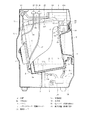
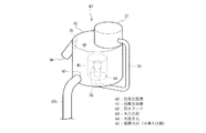
以下、本発明の第1の実施形態に係る乾燥機能付きのドラム式洗濯機について図1ないし図9を参照して説明する。図2の縦断面図は、乾燥機能付きのドラム式洗濯機全体の概略構成を示したもので、外郭を形成する筐体1の内部に、横軸円筒状をなす水槽2を適宜の弾性支持装置3を介して弾性支持している。この水槽2は、実質的に無孔状をなして貯水可能で且つ後述する排水弁4を介して外部に排水可能としていて、前面側を大きく開口した構成としている。該水槽2の下部には水循環用の水取出口2aが形成されている。
(First embodiment)
A drum type washing machine with a drying function according to a first embodiment of the present invention will be described below with reference to FIGS. The longitudinal sectional view of FIG. 2 shows a schematic configuration of the entire drum-type washing machine with a drying function, and a water tank 2 having a horizontal axis is appropriately elastically supported inside a casing 1 forming an outer shell. Elastic support is provided via the device 3. The water tank 2 is substantially non-porous and can store water, and can be drained to the outside through a drain valve 4 to be described later, and has a configuration with a large opening on the front side. A water outlet 2 a for water circulation is formed at the lower part of the water tank 2.

この水槽2の内部には横軸周りたる具体的には傾斜軸周りに回転可能な円筒状のドラム5(回転槽に相当)が設けられており、該ドラム5は、周壁に多数の透孔5aを有し、水槽2と同様に前面側を大きく開口した構成である。さらにこのドラム5は、これを回転可能に支持するドラム軸6を介して前記水槽2の背部に取付固定されたドラム用モータ(駆動モータ)7により回転駆動されるようになっている。このドラム用モータ7はブラシレスモータから構成されており、後述する制御装置24(制御手段)により回転速度が可変制御できるものである。
このようなドラム5や水槽2の前面開口部に対向して、上記筐体1の前面には洗濯物(図示せず)を出し入れするための投入口8が形成されるとともに、該投入口8を開閉するドア9が回動可能に取り付けられている。
Inside the water tank 2 is provided a cylindrical drum 5 (corresponding to a rotating tank) that can rotate around the horizontal axis, specifically around the tilt axis, and the drum 5 has a large number of through holes in the peripheral wall. 5a and having a large opening on the front side as in the case of the water tank 2. Further, the drum 5 is rotationally driven by a drum motor (drive motor) 7 attached and fixed to the back portion of the water tank 2 via a drum shaft 6 that rotatably supports the drum 5. The drum motor 7 is composed of a brushless motor, and the rotation speed can be variably controlled by a control device 24 (control means) described later.
Opposing to the front opening of the drum 5 and the water tub 2, an input port 8 for taking in and out laundry (not shown) is formed on the front surface of the housing 1. A door 9 for opening and closing is attached to be rotatable.

上記水槽2内に貯留された洗濯水や飛散した水飛沫などが水槽2外に漏れないように、該水槽2の前面開口部と上記投入口8間に亘り水封する屈曲自在なベローズ10を設けていて、これは上記ドア9の閉鎖状態にあるとき、その裏面側に接触して投入口8から機外への水の漏洩も防止している。   A bevelable bellows 10 that seals between the front opening of the water tank 2 and the inlet 8 so that washing water stored in the water tank 2 or splashed water droplets do not leak outside the water tank 2. When the door 9 is in a closed state, it contacts the back side of the door 9 to prevent leakage of water from the charging port 8 to the outside of the machine.

そして、本実施形態では乾燥機能としての温風供給手段11および熱交換器12を備えていて、これら温風供給手段11および熱交換器12は、上記水槽2の上下部に連通した循環ダクト13の途中部位に形成されている。具体的には、循環ダクト13の経路中の上流側から上記熱交換器12および温風供給手段11たる送風ファン機構11aおよびヒータ装置11bを順次配設してなる。   And in this embodiment, the hot air supply means 11 and the heat exchanger 12 as a drying function are provided, and these hot air supply means 11 and the heat exchanger 12 are the circulation duct 13 connected to the upper and lower parts of the said water tank 2. It is formed in the middle part of. Specifically, the heat exchanger 12 and the blower fan mechanism 11a and the heater device 11b as the hot air supply means 11 are sequentially arranged from the upstream side in the path of the circulation duct 13.

一方、上記熱交換器12としては、内部に水冷による除湿機能を活用した構成からなり、所謂湿気を含んだ暖気を冷やして水分を凝縮させ排出可能としたもので、これにより常に除湿した乾いた空気を上記ヒータ装置11bで効率良く加熱温風化して、循環ダクト13を経て水槽2およびドラム5内に供給可能としている。   On the other hand, the heat exchanger 12 has a configuration utilizing a dehumidifying function by water cooling inside, and cools warm air containing so-called moisture so that moisture can be condensed and discharged. Air can be efficiently heated and warmed by the heater device 11 b and supplied to the water tank 2 and the drum 5 through the circulation duct 13.

また、筐体1の内底部から前面側上部にかけての部位には、循環ポンプ14を途中部に備えた循環経路15が設けられている。この循環経路15は、循環ポンプ14と吸水管路15aと吐出管路15bとから構成されており、吸水管路15aの一端部は上記循環ポンプ14の吸水側に接続され、他端部は上記水槽2の水取出口2aに接続されている。また吐出管路15bの一端部は、循環ポンプ14の吐出側に接続され、他端部の開口部は後述する泡発生装置28の泡発生タンク29の水入口部30に接続されている。なお、循環ポンプ14の下部は、排水弁4を介して排水ホース(図示せず)に連通されている。   A circulation path 15 having a circulation pump 14 in the middle is provided at a portion from the inner bottom of the housing 1 to the upper part on the front side. The circulation path 15 is composed of a circulation pump 14, a water absorption pipe line 15a, and a discharge pipe line 15b. One end of the water absorption pipe line 15a is connected to the water absorption side of the circulation pump 14, and the other end is the above-mentioned. It is connected to the water outlet 2 a of the water tank 2. One end of the discharge pipe 15b is connected to the discharge side of the circulation pump 14, and the opening at the other end is connected to a water inlet 30 of a foam generation tank 29 of the foam generation device 28 described later. The lower part of the circulation pump 14 is communicated with a drain hose (not shown) through the drain valve 4.

循環経路15内の洗濯水等の水は、泡発生装置28内に一時的に貯留され、泡発生装置28の水出口部31に接続されている水戻口16からドラム5内に吐出される。水戻口16は、ドラム内の上部に臨む位置に配置されている。なお、上記循環ポンプ14は水槽2より下方の部位に配設されている。
一方、上記熱交換器12にも同様のチューブ19を介して、圧力センサからなる泡センサ20を設けている。この泡センサ20は、水槽2内に多量の泡が発生し、やがては熱交換器12内に侵入することに基づく空気圧変動を検知するものである。
Water such as washing water in the circulation path 15 is temporarily stored in the foam generating device 28 and discharged into the drum 5 from the water return port 16 connected to the water outlet 31 of the foam generating device 28. . The water return port 16 is disposed at a position facing the upper part in the drum. The circulation pump 14 is disposed at a site below the water tank 2.
On the other hand, the heat exchanger 12 is also provided with a bubble sensor 20 including a pressure sensor through a similar tube 19. The foam sensor 20 detects a fluctuation in air pressure based on the occurrence of a large amount of foam in the water tank 2 and eventually entering the heat exchanger 12.

なお、水槽2の上部には、2つの水出口を備えた給水手段である給水弁21が設けられており、一方の水出口は給水管路22を介して水槽2の上部に連結されて洗濯水を供給する給水手段として機能し、また他方の水出口は注水管路23を介して熱交換器12の上部に連通され水冷手段用の冷水として供給可能としている。   In addition, a water supply valve 21 which is a water supply means having two water outlets is provided in the upper part of the water tank 2, and one water outlet is connected to the upper part of the water tank 2 through a water supply line 22 and is washed. It functions as a water supply means for supplying water, and the other water outlet communicates with the upper part of the heat exchanger 12 via a water injection pipe 23 so that it can be supplied as cold water for the water cooling means.

上記給水管路22の途中部には洗剤ケース22aが介装されている。給水弁21により水道水の給水制御を行い、給水弁21に連なる給水管路22を介して洗剤ケース22aへ水が供給される。洗剤ケース22a内の洗剤は、この水により溶かされ洗濯水として洗剤投入口22bから水槽2内へ投入される。   A detergent case 22 a is interposed in the middle of the water supply pipe 22. Water supply control is performed by the water supply valve 21, and water is supplied to the detergent case 22 a through the water supply line 22 connected to the water supply valve 21. The detergent in the detergent case 22a is dissolved by this water and is poured into the water tank 2 from the detergent inlet 22b as washing water.

次に、泡発生装置28について、主に図1および3を参照して説明する。泡発生装置28は、主に、エアポンプ27、泡発生タンク29および気泡発生器(空気導入部)32を備える。   Next, the bubble generating device 28 will be described mainly with reference to FIGS. The foam generation device 28 mainly includes an air pump 27, a foam generation tank 29, and a bubble generator (air introduction unit) 32.

エアポンプ27は泡発生部としての泡発生タンク29の上面に備えられ、エアポンプ27より吐出される空気はパイプ33を介して気泡発生器32に送り込まれる。泡発生タンク29は円筒形状をしており、その内底部には、気泡が横方向に噴出するように気泡発生器32が配設されている。泡発生タンク29の周壁の上下方向中間部には水入口部30が設けられており、水入口部30には吐出管路15bの端部が連通されている。泡発生タンク29の周壁の上端部には水出口部31が設けられており、水出口部31は水戻口16を有している。泡発生タンク29の底壁には水抜き孔34が設けられており、この水抜き孔34には下方へ伸びる水排出管35が接続されており、この水排出管35は吸水管路15aに連通されている。所定量の泡が生成されるまでの時間、泡発生タンク29に洗濯水が残るように、水排出管35の太さ寸法は水入口部30より細く設定されている。   The air pump 27 is provided on the upper surface of a bubble generation tank 29 as a bubble generation unit, and the air discharged from the air pump 27 is sent to the bubble generator 32 through the pipe 33. The bubble generation tank 29 has a cylindrical shape, and a bubble generator 32 is disposed at the inner bottom of the bubble generation tank 29 so that bubbles are ejected laterally. A water inlet portion 30 is provided at an intermediate portion in the vertical direction of the peripheral wall of the foam generating tank 29, and the end portion of the discharge pipe 15 b is communicated with the water inlet portion 30. A water outlet 31 is provided at the upper end of the peripheral wall of the foam generation tank 29, and the water outlet 31 has a water return port 16. A water drain hole 34 is provided in the bottom wall of the foam generation tank 29, and a water drain pipe 35 extending downward is connected to the drain hole 34. The water drain pipe 35 is connected to the water suction pipe 15a. It is communicated. The thickness of the water discharge pipe 35 is set narrower than that of the water inlet 30 so that the washing water remains in the foam generation tank 29 until a predetermined amount of foam is generated.

気泡発生器32は、図3(a)に示すように、主に、セラミックスなどの多孔質材36とこの多孔質材36を収納するケース37からなる。ケース37は、多孔質材36を収納する収納部37aと、エアポンプ27から吐出される空気を気泡発生器32に送り込むパイプ33が接続される接続部37bとからなる。図3(b)に示すように、ケース37の収納部37aに多孔質材36を収納することにより気泡発生器32は形成される。気泡発生器32は、例えば、直径が1〜100マイクロメートルの気泡の発生が可能である。   As shown in FIG. 3A, the bubble generator 32 mainly includes a porous material 36 such as ceramics and a case 37 that houses the porous material 36. The case 37 includes a storage portion 37a for storing the porous material 36, and a connection portion 37b to which a pipe 33 for sending air discharged from the air pump 27 to the bubble generator 32 is connected. As shown in FIG. 3B, the bubble generator 32 is formed by storing the porous material 36 in the storage portion 37 a of the case 37. The bubble generator 32 can generate bubbles having a diameter of 1 to 100 micrometers, for example.

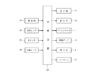
図4には、電気的概略構成が示されている。この図4において、制御手段としての制御装置24は、CPU、ROM、RAM、各種駆動回路などを含んで構成されており、入力側に、操作部25、水位センサ18、泡センサ20、回転センサ26が接続されている。また、該制御装置24の出力側には、負荷としての、表示部17、給水弁21、ドラム用モータ7、循環ポンプ14、排水弁4、エアポンプ27が接続されている。制御装置24は、筐体1前方下部に内蔵されている。
操作部25は、筐体1上部前面に設けられており、運転開始スイッチや、各種設定スイッチなどを含んで構成されている。回転センサ26は、ドラム用モータ7の回転速度を検知するものである。表示部17は、操作部25とともに筐体1上部前面に設けられている。
FIG. 4 shows an electrical schematic configuration. In FIG. 4, a control device 24 as a control means includes a CPU, a ROM, a RAM, various drive circuits, and the like. On the input side, an operation unit 25, a water level sensor 18, a bubble sensor 20, and a rotation sensor. 26 is connected. Further, the display unit 17, the water supply valve 21, the drum motor 7, the circulation pump 14, the drain valve 4, and the air pump 27 are connected to the output side of the control device 24. The control device 24 is built in the lower front part of the housing 1.
The operation unit 25 is provided on the upper front surface of the housing 1 and includes an operation start switch, various setting switches, and the like. The rotation sensor 26 detects the rotation speed of the drum motor 7. The display unit 17 is provided on the upper front surface of the housing 1 together with the operation unit 25.

さて、本実施形態の作用(制御装置24の制御内容)について、図5ないし図7を参照して説明する。制御装置24は、周知のように、給水、洗い(洗剤洗い)、排水、脱水(中間脱水)からなる洗い行程と、給水、すすぎ、排水を複数回繰り返すすすぎ行程と、脱水(最終脱水)行程と、乾燥行程とを順次実行するように制御装置24の出力側の上記負荷を駆動制御するようになっている。   Now, the operation of the present embodiment (the control content of the control device 24) will be described with reference to FIGS. As is well known, the control device 24 performs a washing process including water supply, washing (detergent washing), drainage, and dehydration (intermediate dehydration), a rinsing process in which water supply, rinsing, and drainage are repeated a plurality of times, and a dehydration (final dehydration) process. In addition, the load on the output side of the control device 24 is driven and controlled so that the drying process is sequentially executed.

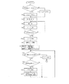
すなわち、図5に示すように、電源スイッチの投入後、操作部25の運転コース設定スイッチを操作して例えば「標準洗濯コース」を選択し、スタートスイッチを操作すると(スタート)、ステップS1で示すように、泡検知フラグがON状態か否かの判断が行われる。泡検知フラグは、後述するように、泡センサ20が先回の洗い行程中の泡の発生量が所定量を超えた場合にONされる。   That is, as shown in FIG. 5, after the power switch is turned on, the operation course setting switch of the operation unit 25 is operated to select, for example, “standard washing course” and the start switch is operated (start), which is shown in step S1. As described above, it is determined whether or not the bubble detection flag is in the ON state. As will be described later, the bubble detection flag is turned ON when the amount of bubbles generated during the last washing process of the bubble sensor 20 exceeds a predetermined amount.

先回の洗い行程中の洗い時の泡の発生量が所定量を超え、泡検知フラグがONされた場合(S1:YES)、今回の洗い行程中の洗いのエアポンプの運転時間(tap)はステップS2で100秒に設定される。先回の洗い行程中の泡の発生量が所定値以下で、泡検知フラグがOFFの場合(S1:NO)、今回の洗い行程中のエアポンプの運転時間(tap)はステップS3で200秒に設定される。   When the amount of foam generated during washing in the previous washing process exceeds a predetermined amount and the foam detection flag is turned on (S1: YES), the operation time (tap) of the washing air pump during this washing process is In step S2, it is set to 100 seconds. When the amount of foam generated during the previous washing process is less than the predetermined value and the foam detection flag is OFF (S1: NO), the operation time (tap) of the air pump during the current washing process is 200 seconds in step S3. Is set.

次にステップS4において、ドラム5に投入された洗濯物の重量検知が行われる。この重量検知はドラム用モータ7に予め決められた一定電圧を一定時間供給し、その間のドラム5の回転速度を測定して検出する。ドラム5の回転速度は、回転センサ26を用いて測定する。洗濯物の重量が検知されると、その検知重量に応じた洗い用水位の設定が行われる。例えば検知重量が重いほど、図2中、C、BまたはAに示すように、洗い用水位は高くなるように設定される。   Next, in step S4, the weight of the laundry put in the drum 5 is detected. In this weight detection, a predetermined constant voltage is supplied to the drum motor 7 for a certain period of time, and the rotational speed of the drum 5 is measured and detected during that time. The rotation speed of the drum 5 is measured using the rotation sensor 26. When the weight of the laundry is detected, the water level for washing corresponding to the detected weight is set. For example, as the detected weight is heavier, the washing water level is set higher as shown in C, B or A in FIG.

次に、洗い行程がスタートする。ステップS5からステップS7において、水槽2の所定水位まで給水を行う。ステップS5では、給水弁21の一方の水出口(給水管路22側)が開かれ、水道水が水槽2内に供給される。このとき洗剤ケース22a内に予め投入されている洗剤が、該水道水と共に水槽2内に供給される。給水が開始されると、ドラム用モータ7が起動され、ドラム5を、例えば45rpmの回転速度の正転20秒、2秒停止、反転20秒のサイクルで回転させる(ステップS6)。水槽2内に供給される水道水量は、水位センサ18によって検出され、ステップS7で水が水槽2内の所定水位に達したか否かが判断され、水が水槽2内の所定水位に達するまでステップS5からステップS7は繰り返される。そして、洗濯物の検知重量に応じて設定された洗い用水位(例えば、A、BまたはC)になると、ステップS6Aとなり、給水弁21は閉じられる。ステップS6AはステップS6と同じである。   Next, the washing process starts. In steps S5 to S7, water is supplied to a predetermined water level in the water tank 2. In step S <b> 5, one water outlet (water supply pipe 22 side) of the water supply valve 21 is opened, and tap water is supplied into the water tank 2. At this time, the detergent previously put in the detergent case 22a is supplied into the water tank 2 together with the tap water. When the water supply is started, the drum motor 7 is started, and the drum 5 is rotated in a cycle of, for example, a forward rotation of 45 rpm at a rotation speed of 45 rpm, a stop of 2 seconds, and a reverse rotation of 20 seconds (step S6). The amount of tap water supplied into the aquarium 2 is detected by the water level sensor 18, and it is determined whether or not the water has reached a predetermined water level in the aquarium 2 in step S 7 until the water reaches a predetermined water level in the aquarium 2. Steps S5 to S7 are repeated. And if it becomes the water level for washing (for example, A, B, or C) set according to the detected weight of laundry, it will become step S6A and the water supply valve 21 will be closed. Step S6A is the same as step S6.

次に、ステップS8にて循環ポンプ14を駆動(オン)して、洗濯水を水槽2内および循環経路15内を循環させる。具体的には、水槽2内の洗濯水を水取出口2aから吸入し吸水管路15aを介して循環ポンプ14内に導入する。そして循環ポンプ14から吐出された洗濯水は吐出管路15bおよび泡発生装置28を介して水戻口16から水槽2内に吐出される。循環ポンプ14の駆動時間T1(図8参照)は、例えば90秒である。このように、洗濯水を水槽2内および循環経路15内を循環させることにより、洗剤を十分に洗濯水に溶け込ませることができる。   Next, in step S8, the circulation pump 14 is driven (turned on) to circulate the wash water in the water tank 2 and the circulation path 15. Specifically, the washing water in the water tank 2 is sucked from the water outlet 2a and introduced into the circulation pump 14 through the water suction pipe 15a. The washing water discharged from the circulation pump 14 is discharged into the water tank 2 from the water return port 16 via the discharge pipe 15b and the foam generating device 28. The driving time T1 (see FIG. 8) of the circulation pump 14 is, for example, 90 seconds. In this way, the detergent can be sufficiently dissolved in the washing water by circulating the washing water in the water tank 2 and the circulation path 15.

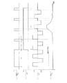
次に、ステップS9に移行する。ステップS9では、泡発生装置28のエアポンプ27を駆動(オン)して泡をドラム5内に導入し、洗剤を洗濯物に拡散させる。具体的には、図8のタイムチャートに示す。図8(a)は洗い行程の洗い時の循環ポンプ14のオン(縦軸)を示し、(b)は洗い時のエアポンプ27のオン(縦軸)を示す。図8(c)は洗い時のドラム5の正転、逆転(縦軸)を示し、(d)は泡センサ20の出力する泡検知値(縦軸)を示している。横軸は時間を示す。循環ポンプ14の停止と同時に泡発生装置28のエアポンプ27の駆動をスタートさせる。エアポンプ27の駆動中、循環ポンプ14は断続駆動を行い、T2(例えば45秒)停止後T3(例えば10秒)駆動というサイクルを3〜4回繰り返す(一定時間T4)。   Next, the process proceeds to step S9. In step S9, the air pump 27 of the foam generating device 28 is driven (turned on) to introduce foam into the drum 5, and the detergent is diffused into the laundry. Specifically, it is shown in the time chart of FIG. FIG. 8A shows that the circulation pump 14 is turned on (vertical axis) during washing in the washing process, and FIG. 8B shows that the air pump 27 is turned on (vertical axis) during washing. FIG. 8C shows normal rotation and reverse rotation (vertical axis) of the drum 5 at the time of washing, and FIG. 8D shows a foam detection value (vertical axis) output from the foam sensor 20. The horizontal axis indicates time. Simultaneously with the stop of the circulation pump 14, the driving of the air pump 27 of the foam generating device 28 is started. While the air pump 27 is being driven, the circulation pump 14 is intermittently driven, and a cycle of T3 (for example, 10 seconds) driving after T2 (for example, 45 seconds) is stopped 3 to 4 times (fixed time T4).

泡発生装置28の泡発生タンク29内では、エアポンプ27の駆動により泡が生成される。生成された泡は、循環ポンプ14の断続駆動における10秒間駆動により洗濯水と共にドラム5内上部に吐出される。循環ポンプ14の駆動中は、ドラム用モータ7の駆動を停止しドラム5は静止する。ドラム5内に泡が吐出されている最中に、ドラム5が回転していると泡が弾き飛ばされ、洗剤が洗濯物に効率よく拡散しないからである。また、循環ポンプ14の駆動中に、ドラム5は完全に停止しなくてもよく、ドラム5が所定値以下の低速で揺動正逆回転していてもよい。ドラム5内に泡が吐出されている最中、洗濯物が適度に揺動していたほうが効率よく泡を拡散できるからである。   In the foam generation tank 29 of the foam generation device 28, bubbles are generated by driving the air pump 27. The generated foam is discharged into the upper part of the drum 5 together with the wash water by driving for 10 seconds in the intermittent drive of the circulation pump 14. While the circulation pump 14 is being driven, the drum motor 7 is stopped and the drum 5 is stopped. This is because if the drum 5 rotates while the foam is being discharged into the drum 5, the foam is blown off and the detergent does not diffuse efficiently into the laundry. Further, while the circulation pump 14 is being driven, the drum 5 may not be completely stopped, and the drum 5 may be oscillating forward and reverse at a low speed equal to or lower than a predetermined value. This is because the foam can be diffused more efficiently if the laundry is moderately swung while the foam is being discharged into the drum 5.

次に、ステップS10に移行し、洗い行程時間が例えば15分経過したか否かの判断を行う。なお、ステップS5において、図示しない洗い行程タイマーの計時を開始する。洗い行程タイマーが計時を開始して15分経過した場合は(S10:YES)、ドラム用モータ7の駆動を止めドラム5の回転を停止させ、洗い行程は終了する。洗い行程タイマーが15分経過していない場合は(S10:NO)、次ステップS11に移行する。   Next, it transfers to step S10 and it is judged whether the washing process time passed, for example for 15 minutes. In step S5, timing of a washing process timer (not shown) is started. When 15 minutes have elapsed since the washing process timer started measuring time (S10: YES), the driving of the drum motor 7 is stopped, the rotation of the drum 5 is stopped, and the washing process is completed. When the washing process timer has not elapsed for 15 minutes (S10: NO), the process proceeds to the next step S11.

ステップS11では、水槽2内に多量の泡が発生し、圧力センサからなる泡センサ20が泡に基づく空気圧変動を検知し、泡が所定量を超えたか否かを検知する。泡が所定量を超えていない場合(S11:NO)、ステップS10に戻り再びそれ以降の処理を行う。泡が検出所定値を超えた場合(図8参照、S11:YES)、次ステップS12に移行する。   In step S11, a large amount of bubbles are generated in the water tank 2, and the bubble sensor 20 including a pressure sensor detects a fluctuation in air pressure based on the bubbles, and detects whether or not the bubbles exceed a predetermined amount. If the foam does not exceed the predetermined amount (S11: NO), the process returns to step S10 and the subsequent processing is performed again. When the bubble exceeds the detection predetermined value (see FIG. 8, S11: YES), the process proceeds to the next step S12.

ステップS12では、ドラム5の回転速度を減速する。具体的には、現時点でのドラム5の回転速度が、例えば45rpmであるのを30rpmまで減速する(図8参照)。水槽2内の泡が所定量を超えた場合、水槽2とドラム5との間に滞留する泡による粘性が、ドラム用モータ7の過剰な負荷となるのを防止するためである。次にステップS13に移行して、制御装置24に配設された図示しないEEPROMに泡検知フラグがONしたことを記憶し、ステップS10に戻り再びそれ以降の処理を行う。   In step S12, the rotational speed of the drum 5 is reduced. Specifically, the current rotational speed of the drum 5 is reduced from, for example, 45 rpm to 30 rpm (see FIG. 8). This is to prevent the viscosity due to the bubbles staying between the water tank 2 and the drum 5 from becoming an excessive load on the drum motor 7 when the foam in the water tank 2 exceeds a predetermined amount. Next, the process proceeds to step S13, where the fact that the bubble detection flag is turned on is stored in an EEPROM (not shown) provided in the control device 24, and the process returns to step S10 to perform the subsequent processing again.

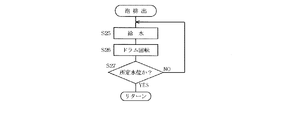
以上の処理を経て洗い行程の洗いが終了し、図6に示すステップS15以降の排水に移行する。
ステップS15、S16では、排水弁4が開かれ洗濯水が排水される。水位センサ18が水槽2内の水位が0と検知するまで(S16:NO)、排水が続行される。水位センサ18により水位が0と検知された場合(S16:YES)、次ステップS17に移行する。
After the above processing, washing in the washing process is completed, and the process proceeds to drainage after step S15 shown in FIG.
In steps S15 and S16, the drain valve 4 is opened and the washing water is drained. Drainage is continued until the water level sensor 18 detects that the water level in the water tank 2 is 0 (S16: NO). If the water level is detected by the water level sensor 18 (S16: YES), the process proceeds to the next step S17.

ステップS17からS20では、ドラム5を一方向に高速度で回転させ、ドラム5の回転速度が900rpmになるまで回転速度を加速させる。具体的には、ステップS17においてドラム用モータ7を駆動しドラム5を回転させる(脱水)。ステップS18では、回転センサ26によりドラム5の回転速度を検知し、ドラム5の回転速度が900rpmに達したか否かを判断する。ドラム5の回転速度が900rpmに達していない場合(S18:NO)、ステップS19にてドラム5の回転速度を上昇させる。ドラム5の回転速度が900rpmに達した場合(S18:YES)、ステップS21に移行してドラム5の回転を5分間継続した後、ドラム5の回転を停止して洗い行程の脱水を終了し、次行程であるすすぎ行程に進む。   In steps S17 to S20, the drum 5 is rotated in one direction at a high speed, and the rotational speed is accelerated until the rotational speed of the drum 5 reaches 900 rpm. Specifically, in step S17, the drum motor 7 is driven to rotate the drum 5 (dehydration). In step S18, the rotation speed of the drum 5 is detected by the rotation sensor 26, and it is determined whether or not the rotation speed of the drum 5 has reached 900 rpm. If the rotational speed of the drum 5 has not reached 900 rpm (S18: NO), the rotational speed of the drum 5 is increased in step S19. When the rotational speed of the drum 5 has reached 900 rpm (S18: YES), the process proceeds to step S21 and continues to rotate the drum 5 for 5 minutes. Then, the rotation of the drum 5 is stopped and the dehydration of the washing process is terminated. Proceed to the next rinsing process.

ステップS20では、回転センサ26によりドラム5の回転速度の上昇が毎分50rpm以下か否かを判断する。ドラム5の回転速度の上昇が毎分50rpmより大きい場合(S20:NO)、ステップS18に戻りドラム5の回転速度が900rpmになるまで、ステップS19にてドラム用モータ7はドラム5の回転速度を上昇させる。ドラム5の回転速度の上昇が毎分50rpm以下の場合(S20:YES)、ステップS22においてドラム用モータ7の駆動を停止させドラム5の回転を止める。
ステップS23では、泡が過剰に発生しドラム5の泡による負荷が所定値以上と判断して泡検知フラグをONとしてEEPROMに記録する。次回の洗濯運転の洗い行程時にエアポンプ27の駆動時間を短くして泡の発生量を抑制するためである(S1、S2)。
In step S20, the rotation sensor 26 determines whether or not the increase in the rotation speed of the drum 5 is 50 rpm or less. If the increase in the rotational speed of the drum 5 is larger than 50 rpm per minute (S20: NO), the process returns to step S18 and the drum motor 7 increases the rotational speed of the drum 5 in step S19 until the rotational speed of the drum 5 reaches 900 rpm. Raise. When the increase in the rotational speed of the drum 5 is 50 rpm or less (S20: YES), the driving of the drum motor 7 is stopped and the rotation of the drum 5 is stopped in step S22.
In step S23, it is determined that excessive bubbles are generated and the load due to the bubbles on the drum 5 is equal to or greater than a predetermined value, and the bubble detection flag is turned on and recorded in the EEPROM. This is because the driving time of the air pump 27 is shortened during the washing process of the next washing operation to suppress the amount of foam generated (S1, S2).

次にステップS24にて泡排出を行う。具体的には、図7のサブルーチンで示すように、ステップS25からS27において、ドラム5を回転させながら所定水位になるまで水槽2へ給水を行い、過剰に発生した泡を洗い流す。すなわち、ステップS25にて給水弁21を開いて水槽2へ給水を開始し、ドラム用モータ7を駆動しドラム5を回転させる(ステップS26)。ステップS27にて水位センサ18により水槽2内の水が所定水位に達したか否かを判断する。水槽2内の水が所定水位に達していない場合(S27:NO)、ステップS25に戻り、ステップS25以降の処理を再び行う。水槽2内の水が所定水位に達した場合(S27:YES)、ステップS15以降の処理を行い、次行程であるすすぎ行程へ進む。   Next, bubble discharge is performed in step S24. Specifically, as shown in the subroutine of FIG. 7, in steps S25 to S27, water is supplied to the water tank 2 until the water level reaches a predetermined level while rotating the drum 5, and the excessively generated bubbles are washed away. That is, in step S25, the water supply valve 21 is opened to start water supply to the water tank 2, and the drum motor 7 is driven to rotate the drum 5 (step S26). In step S27, the water level sensor 18 determines whether or not the water in the water tank 2 has reached a predetermined water level. When the water in the water tank 2 has not reached the predetermined water level (S27: NO), the process returns to step S25, and the processes after step S25 are performed again. When the water in the aquarium 2 reaches a predetermined water level (S27: YES), the process after step S15 is performed, and the process proceeds to the rinsing process which is the next process.

以上のようにして、洗い行程の洗いにおいて泡発生装置28で発生させた泡をドラム5内に投入して、ドラム内の衣類に洗剤を拡散する(ステップS9)。さらに、使用者の使用態様、例えば、使用者が使用する洗剤の種類や量によっては、洗い行程の洗いまたは脱水の最中に泡が過剰に発生するような場合があるが、上記泡検知フラグのON状態を上記EEPROMに記憶させることによって、次回の洗濯運転の洗い行程での泡の発生を抑制することが可能となる。   As described above, the foam generated by the foam generating device 28 in the washing process is put into the drum 5 and the detergent is diffused in the clothes in the drum (step S9). Further, depending on the user's usage mode, for example, the type and amount of detergent used by the user, foam may be excessively generated during washing or dehydration in the washing process. By storing the ON state in the EEPROM, it is possible to suppress the generation of bubbles in the washing process of the next washing operation.

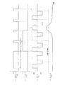
洗い行程の脱水終了後(ステップS21)、すすぎ行程へ移行する。すすぎ行程では、図9に示すように、ドラム5を、例えば45rpmの回転速度の正転20秒、2秒停止、反転20秒のサイクルで回転させ、循環ポンプ14は連続運転させる。すすぎ時の所定期間T5において、循環ポンプ14を駆動しながらエアポンプ27を連続駆動する。   After the dehydration of the washing process is completed (step S21), the process proceeds to the rinsing process. In the rinsing process, as shown in FIG. 9, the drum 5 is rotated, for example, at a rotation speed of 45 rpm in a forward rotation 20 second, 2 second stop, reverse 20 second cycle, and the circulation pump 14 is continuously operated. In a predetermined period T5 at the time of rinsing, the air pump 27 is continuously driven while the circulation pump 14 is driven.

以上のように本実施形態では、泡発生装置28は、泡発生タンク29と、この泡発生タンク29に循環経路15の水取出し側の水を導入する水入口部30と、泡発生タンク29に水入口部30より下方に位置して設けられ、エアポンプ27からの空気を導入して泡を発生させる気泡発生器(空気導入部)32と、水入口部30よりも上方に位置して設けられ、泡発生タンク29からの泡を水とともに循環経路15の水戻し側に供給する水出口部31とを有する。   As described above, in this embodiment, the foam generating device 28 includes the foam generating tank 29, the water inlet portion 30 for introducing water on the water extraction side of the circulation path 15 into the foam generating tank 29, and the foam generating tank 29. A bubble generator (air introduction part) 32 that is provided below the water inlet 30 and introduces air from the air pump 27 to generate bubbles, and is provided above the water inlet 30. And a water outlet 31 for supplying the foam from the foam generation tank 29 to the water return side of the circulation path 15 together with water.

このため、気泡発生器32に空気を導入すると、水入口部30上端から水出口部31に至る空間に泡が発生し蓄積し、さらに泡が発生した場合には水出口部31から徐々に泡が放出される。ここで水入口部30から水出口部31に所定の空間があることと、泡発生タンク29底面から水入口部30までの間に所定量の洗濯液があることで、洗濯水より泡のほうが比重が小さく、泡発生装置28は泡を効果的に発生させることができる。   For this reason, when air is introduced into the bubble generator 32, bubbles are generated and accumulated in the space from the upper end of the water inlet portion 30 to the water outlet portion 31, and when bubbles are further generated, the bubbles are gradually generated from the water outlet portion 31. Is released. Here, the foam is better than the washing water because there is a predetermined space from the water inlet part 30 to the water outlet part 31 and there is a predetermined amount of washing liquid between the bottom surface of the foam generation tank 29 and the water inlet part 30. The specific gravity is small, and the bubble generator 28 can generate bubbles effectively.

さらに、泡発生タンク29の底部に循環経路15の水取出し側に連通する水抜き孔34が形成されている。
このため、泡発生タンク29に貯まったままの洗濯水は、水抜き孔34から循環経路15を介して排水されるため、上記乾燥機能付きのドラム式洗濯機が、長時間使用されない場合でも内部での上記洗濯水の腐食を防止することができる。
さらに、循環経路15の水戻口16はドラム5内の上部に臨む位置に配置されている。
このため、水戻口16から洗濯水と共に吐出される泡を確実にドラム5内に投入し、泡を洗濯物に付着させることができる。
Further, a drain hole 34 communicating with the water extraction side of the circulation path 15 is formed at the bottom of the foam generation tank 29.
For this reason, since the washing water stored in the foam generation tank 29 is drained from the drain hole 34 via the circulation path 15, the drum type washing machine with the drying function is not used for a long time. Corrosion of the washing water can be prevented.
Further, the water return port 16 of the circulation path 15 is disposed at a position facing the upper part in the drum 5.
For this reason, the foam discharged with the washing water from the water return port 16 can be reliably put into the drum 5 and the foam can adhere to the laundry.

さらに、制御装置(制御手段)24は、洗濯運転の洗いの初期において、所定時間循環ポンプ14を連続駆動した後、一定時間エアポンプ27を連続駆動するとともに循環ポンプ14を断続駆動し、その一定時間中の循環ポンプ14の駆動時にはドラム5の回転速度を所定値以下に制御する。   Further, the control device (control means) 24 continuously drives the circulation pump 14 for a predetermined time at the initial stage of washing in the washing operation, then continuously drives the air pump 27 for a certain period of time, and intermittently drives the circulation pump 14 for a certain period of time. When the circulating pump 14 is driven, the rotational speed of the drum 5 is controlled to a predetermined value or less.

このため、洗濯水を水槽2内および循環経路15内を循環させることにより、洗剤を十分に洗濯水に溶け込ませることができる。さらに、循環ポンプ14の駆動中は、ドラム用モータ7の駆動を停止しドラム5は静止状態にあるため、ドラム5内に泡が吐出されている最中に、泡は弾き飛ばされることはなく洗濯物に効率よく拡散させることができる。また、循環ポンプ14の駆動中にドラム5を低速で揺動正逆回転させると、ドラム5内に泡が吐出されている最中は、洗濯物が適度に揺動し効率よく泡を拡散させることができる。   For this reason, the detergent can be sufficiently dissolved in the washing water by circulating the washing water in the water tank 2 and the circulation path 15. Furthermore, since the drum motor 7 is stopped and the drum 5 is in a stationary state while the circulation pump 14 is being driven, the bubbles are not blown off while the bubbles are being discharged into the drum 5. It can be efficiently diffused into the laundry. Further, when the drum 5 is swung forward and backward at low speed while the circulation pump 14 is being driven, the laundry is swung moderately and the bubbles are efficiently diffused while the bubbles are being discharged into the drum 5. be able to.

さらに、水槽2内に発生する泡の量を検出する泡センサ(泡検出手段)20を備え、制御装置(制御手段)24は、泡センサ20が所定量以上の泡を検出したときには、次回の洗濯運転の洗い時におけるエアポンプ27の駆動時間を短く制御する。
このため、使用者が使用する洗剤の種類や量によっては、洗い行程の最中に泡が過剰に発生するような場合があるが、次回の洗濯運転の洗い行程での泡の発生を抑制することができる。
Furthermore, a foam sensor (foam detection means) 20 that detects the amount of foam generated in the water tank 2 is provided, and the control device (control means) 24 detects the next time when the foam sensor 20 detects a foam of a predetermined amount or more. The drive time of the air pump 27 during the washing operation is controlled to be short.
For this reason, depending on the type and amount of detergent used by the user, foam may be generated excessively during the washing process, but the generation of foam in the washing process of the next washing operation is suppressed. be able to.

さらに、制御装置(制御手段)24は、洗濯運転の脱水時において、ドラム5の負荷が所定値以上と判断したときには、次回の洗濯運転の洗い時におけるエアポンプ5の駆動時間を短く制御する。
このため、次回の洗濯運転の洗い行程時に泡の発生量を抑制することができ、使用者が使用する洗剤の種類や量によって、適宜、洗い行程時の泡の発生量を調節することができる。
Further, when the load of the drum 5 is determined to be equal to or greater than a predetermined value at the time of dehydration in the washing operation, the control device (control means) 24 controls the drive time of the air pump 5 to be shortened at the time of washing in the next washing operation.
For this reason, the amount of foam generated during the washing process of the next washing operation can be suppressed, and the amount of foam generated during the washing process can be appropriately adjusted according to the type and amount of detergent used by the user. .

さらに、制御装置(制御手段)24は、洗濯運転のすすぎ時の所定期間において、循環ポンプ14を駆動しながらエアポンプ27を駆動するように制御する。
このため、すすぎ時に気泡発生器32から気泡を生成することによって、気泡発生器32の多孔質材36のリントや洗剤などのつまりを解消することができる。
Further, the control device (control means) 24 performs control so that the air pump 27 is driven while the circulation pump 14 is driven during a predetermined period when the washing operation is rinsed.
For this reason, by generating bubbles from the bubble generator 32 at the time of rinsing, it is possible to eliminate clogging of the porous material 36 of the bubble generator 32 such as lint and detergent.

(第2の実施形態)
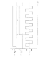
本発明の第2の実施形態につき、主に図10を参照して説明する。図10は第1の実施形態に係る図8に相当するタイムチャートである。なお、上記第1の実施形態と同一部分には同一符号を付し、その詳細な説明は省略する。本実施形態は、泡センサ20が泡検出所定値を検知した後の、制御装置24(図4参照)によるドラム5およびエアポンプ27の制御方法で第1の実施形態と異なる。
(Second Embodiment)
A second embodiment of the present invention will be described mainly with reference to FIG. FIG. 10 is a time chart corresponding to FIG. 8 according to the first embodiment. The same parts as those in the first embodiment are denoted by the same reference numerals, and detailed description thereof is omitted. This embodiment is different from the first embodiment in the control method of the drum 5 and the air pump 27 by the control device 24 (see FIG. 4) after the foam sensor 20 detects the foam detection predetermined value.

本実施形態では、泡センサ20が、泡が所定量を超えたと判断した場合(図5参照、S11:YES)、泡センサ20の泡が所定量を超えたと判断した時点でエアポンプ27の駆動を停止する。エアポンプ27の駆動を停止することで、泡発生装置28(図1参照)が泡の発生を停止する。このことにより、ドラム5内の泡は、上記所定量より増えることはない。なお、第1の実施形態では、泡センサ20が、泡が所定量を超えたと判断した場合(S11:YES)、ドラム5の回転速度を減速したが(S12)、本実施形態ではドラム5の回転速度の変更はしない。   In this embodiment, when the bubble sensor 20 determines that the foam has exceeded a predetermined amount (see FIG. 5, S11: YES), the air pump 27 is driven when it is determined that the foam sensor 20 has exceeded the predetermined amount. Stop. By stopping the driving of the air pump 27, the bubble generating device 28 (see FIG. 1) stops the generation of bubbles. As a result, the foam in the drum 5 does not increase above the predetermined amount. In the first embodiment, when the bubble sensor 20 determines that the bubble exceeds a predetermined amount (S11: YES), the rotational speed of the drum 5 is reduced (S12). Do not change the rotation speed.

以上のように本実施形態では、制御装置(制御手段)24は、泡センサ20が所定量以上の泡を検出したときには、エアポンプ27を停止するように制御する。
このため、洗い行程での泡の過剰な発生を抑制しつつ、ドラム5の回転速度を落とすことのない効率的な洗いを行うことができる。このような場合に、泡発生装置28からの泡の発生において、泡を泡センサ20で検知し、泡の所定量の発生を検知した場合には、エアポンプ27を停止し泡発生装置28への空気導入を停止するものである。
As described above, in the present embodiment, the control device (control means) 24 controls the air pump 27 to stop when the bubble sensor 20 detects a predetermined amount or more of bubbles.
For this reason, the efficient washing | cleaning which does not reduce the rotational speed of the drum 5 can be performed, suppressing the excessive generation | occurrence | production of the bubble in a washing process. In such a case, in the generation of bubbles from the bubble generator 28, the bubbles are detected by the bubble sensor 20, and when the generation of a predetermined amount of bubbles is detected, the air pump 27 is stopped and the bubbles are generated to the bubble generator 28. Air introduction is stopped.

(第3の実施形態)
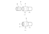
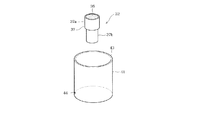
本発明の第3の実施形態につき、図11、12を参照して説明する。図11は第3の実施形態に係る泡発生装置40の全体斜視図であり、図12は泡発生装置40の主要部である泡発生容器41と気泡発生器32の拡大斜視図である。なお、上記第1の実施形態と同一部分には同一符号を付し、その詳細な説明は省略する。なお、説明の便宜上、図2、8をも参照する。本実施形態は、泡発生装置40の構成が第1の実施形態に係る泡発生装置28の構成と異なる。
(Third embodiment)
A third embodiment of the present invention will be described with reference to FIGS. FIG. 11 is an overall perspective view of the foam generating device 40 according to the third embodiment, and FIG. 12 is an enlarged perspective view of the foam generating container 41 and the bubble generator 32 which are main parts of the foam generating device 40. The same parts as those in the first embodiment are denoted by the same reference numerals, and detailed description thereof is omitted. For convenience of explanation, reference is also made to FIGS. This embodiment differs in the structure of the foam generation apparatus 40 from the structure of the foam generation apparatus 28 which concerns on 1st Embodiment.

本実施形態に係る泡発生装置40は、主に、貯水タンク42、エアポンプ27、泡発生部としての泡発生容器41および気泡発生器32を備える。貯水タンク42の内部にカップ状の泡発生容器41を配設し、洗濯水の貯留部を2重管構造とし、泡発生容器41の内部に空気導入部となる気泡発生器32を配設している。   The foam generation device 40 according to the present embodiment mainly includes a water storage tank 42, an air pump 27, a foam generation container 41 as a foam generation unit, and a bubble generator 32. A cup-shaped foam generating container 41 is disposed inside the water storage tank 42, the washing water storage part has a double pipe structure, and a bubble generator 32 serving as an air introduction part is disposed inside the foam generating container 41. ing.

具体的には、貯水タンク42の内部底面にはカップ状の泡発生容器41が開口部を上にして配設されている。該開口部は泡発生容器41の水入口部43を構成する。泡発生容器41の底部には気泡発生器32がその開口部を上向きにして立設状態で配設されている。泡発生容器41の周壁底部には水抜き孔44が有り、泡発生容器41内の水を少量ずつ貯水タンク42に流出させるために設けられている。気泡発生器32が泡を生成している期間中、泡発生容器41内に洗濯水が泡生成に支障無く残るように、水抜き孔44は小径に設定されている。   Specifically, a cup-shaped foam generating container 41 is disposed on the inner bottom surface of the water storage tank 42 with the opening portion facing upward. The opening constitutes a water inlet 43 of the foam generating container 41. A bubble generator 32 is disposed at the bottom of the bubble generation container 41 in an upright state with its opening facing upward. A water drain hole 44 is provided at the bottom of the peripheral wall of the foam generating container 41, and is provided to allow the water in the foam generating container 41 to flow out into the water storage tank 42 little by little. During the period in which the bubble generator 32 is generating bubbles, the drain hole 44 is set to have a small diameter so that the washing water remains in the bubble generating container 41 without hindering bubble generation.

貯水タンク42の上面にはエアポンプ27が配設されており、エアポンプ27から吐出される空気がパイプ33を介して気泡発生器32のケース37接続部37bに導入される。貯水タンク42の周壁の上下方向上端部には水出口部31となる開口穴が設けられており、水出口部31は水戻口16を有している。貯水タンク42の周壁の上下方向下端部には給排水口45となる開口穴が設けられており、給排水口45には吐出管路15bが連結されており、給排水口45は循環ポンプ14と連通している。   An air pump 27 is disposed on the upper surface of the water storage tank 42, and air discharged from the air pump 27 is introduced into the case 37 connection portion 37 b of the bubble generator 32 through the pipe 33. The upper end of the peripheral wall of the water storage tank 42 is provided with an opening hole serving as a water outlet 31, and the water outlet 31 has a water return port 16. An opening hole serving as a water supply / drain port 45 is provided at the lower end in the vertical direction of the peripheral wall of the water storage tank 42, a discharge pipe 15 b is connected to the water supply / drain port 45, and the water supply / drain port 45 communicates with the circulation pump 14. ing.

以上のように、泡発生装置40は、この下部に循環経路15(図2参照)の水取出し側に給排水口(水導入口部)45を介して連通する貯水タンク42を備え、この貯水タンク42内に上面が開口して水入口部43とし且つ側壁下部に水抜き孔44を有するカップ状の泡発生容器41が設けられている。この泡発生容器41内には気泡発生器(空気導入部)32が配置され、貯水タンク42の上部に水出口部31が設けられている。   As described above, the foam generating device 40 is provided with a water storage tank 42 communicating with the water outlet side of the circulation path 15 (see FIG. 2) via the water supply / drain port (water inlet port) 45 at the lower portion thereof. A cup-shaped foam generating container 41 having an upper surface opened in 42 to serve as a water inlet 43 and a drain hole 44 in the lower portion of the side wall is provided. A bubble generator (air introduction part) 32 is arranged in the foam generation container 41, and a water outlet part 31 is provided in the upper part of the water storage tank 42.

上記泡発生装置40の構成により、循環ポンプ14から吐出され吐出管路15bを介して給排水口45から導入された洗濯水は、貯水タンク42内を埋めていき、水位が泡発生容器41の水入口部43まで達した時点で、泡発生容器41内に洗濯水が満たされる。さらに給排水口45から洗濯水を導入して、洗濯水の水位が循環ポンプ14の上端まで達した後、水出口部31から洗濯水を排出し、水戻口16より洗濯水をドラム内へ投入する。   With the configuration of the foam generating device 40, the wash water discharged from the circulation pump 14 and introduced from the water supply / drain port 45b through the discharge pipe 15b fills the water storage tank 42, and the water level is the water in the foam generating container 41. When the inlet 43 is reached, the foam generating container 41 is filled with washing water. Furthermore, after the washing water is introduced from the water supply / drain port 45 and the water level of the washing water reaches the upper end of the circulation pump 14, the washing water is discharged from the water outlet 31 and the washing water is put into the drum from the water return port 16. To do.

循環ポンプ14を停止させた場合には、給排水口45から洗濯水が循環ポンプ14側に戻り、貯水タンク42内の洗濯水の水位が下がり、泡発生容器41内にのみ洗濯水が残る。泡発生容器41の水抜き孔44から徐々に排水された洗濯水は給排水口45、吐出管路15bを介して循環ポンプ14側に戻り、十分な時間の経過後には貯水タンク42内の洗濯水は無くなり、上記ドラム式洗濯機の不使用時に、その内部に残った洗濯水が腐食するといった不具合はない。   When the circulation pump 14 is stopped, the washing water returns to the circulation pump 14 side from the water supply / drain port 45, the water level of the washing water in the water storage tank 42 is lowered, and the washing water remains only in the foam generating container 41. The washing water gradually drained from the drain hole 44 of the foam generating container 41 returns to the circulation pump 14 side through the water supply / drain port 45 and the discharge pipe 15b, and after a sufficient time has passed, the washing water in the water storage tank 42 is returned. There is no problem that the washing water remaining inside the drum type washing machine corrodes when the drum type washing machine is not used.

さらに、貯水タンク42内の泡発生容器41にのみ洗濯水が残っている状態で気泡発生器32が泡を生成するため、貯水タンク42内の大容積の空間に泡を貯めることができ、泡発生装置40は効率よく泡を発生することができる。
さらに、洗い行程の洗い時の初期に、エアポンプ27の駆動中、循環ポンプ14は断続駆動を行い、図8に示す、T2(例えば45秒)停止後T3(例えば10秒)駆動というサイクルを7回程度繰り返すことにより、ドラム5内に十分な泡を供給することができる。
Further, since the bubble generator 32 generates bubbles in the state where the washing water remains only in the bubble generation container 41 in the water storage tank 42, the bubbles can be stored in a large volume space in the water storage tank 42. The generator 40 can generate bubbles efficiently.
Further, at the beginning of the washing process, the circulation pump 14 is intermittently driven while the air pump 27 is being driven, and a cycle of T3 (for example, 10 seconds) after stopping T2 (for example, 45 seconds) shown in FIG. By repeating about several times, sufficient foam can be supplied into the drum 5.

図面中、2は水槽、2aは水取出口、4は排水弁、5はドラム、7はドラム用モータ(駆動モータ)、14は循環ポンプ、15は循環経路、16は水戻口、20は泡センサ(泡検出手段)、24は制御装置(制御手段)、27はエアポンプ、28は泡発生装置、29は泡発生タンク(泡発生部)、30は水入口部、31は水出口部、32は気泡発生器(空気導入部)、34は水抜き孔、40は泡発生装置、41は泡発生容器(泡発生部)、42は貯水タンク、43は水入口部、44は水抜き孔、45は給排水口(水導入口部)である。   In the drawings, 2 is a water tank, 2a is a water outlet, 4 is a drain valve, 5 is a drum, 7 is a drum motor (drive motor), 14 is a circulation pump, 15 is a circulation path, 16 is a water return port, and 20 is Foam sensor (foam detection means), 24 is a control device (control means), 27 is an air pump, 28 is a foam generation device, 29 is a foam generation tank (foam generation portion), 30 is a water inlet portion, 31 is a water outlet portion, 32 is a bubble generator (air introduction part), 34 is a water draining hole, 40 is a foam generating device, 41 is a foam generating container (foam generating part), 42 is a water storage tank, 43 is a water inlet, and 44 is a water draining hole. , 45 is a water supply / drainage port (water introduction port).

Claims (8)

貯水が可能で下部に水循環用水取出口を備えた水槽と、
この水槽の内部に回転自在に設けられたドラムと、
このドラムを回転駆動する駆動モータと、
循環ポンプを備え、その駆動により前記水取出口から取出した前記水槽内の水を水戻口を介して前記ドラム内に戻す循環経路と、
この循環経路に介装され、泡を発生させるためのエアポンプを備えた泡発生装置と、
前記駆動モータ、循環ポンプ及びエアポンプ等を駆動して洗濯運転を制御する制御手段とを備え、
前記泡発生装置は、底部に循環経路の水取出し側に連通する水抜き孔が形成されている泡発生部と、この泡発生部に前記循環経路の水取出し側の水を導入する水入口部と、前記泡発生部に前記水入口部より下方に位置して設けられ、前記エアポンプからの空気を導入して泡を発生させる空気導入部と、前記水入口部よりも上方に位置して設けられ、前記泡発生部からの泡を水とともに前記循環経路の水戻し側に供給する水出口部とを有することを特徴とするドラム式洗濯機。
A water tank capable of storing water and having a water circulation outlet at the bottom;
A drum rotatably provided in the water tank;
A drive motor for rotating the drum;
A circulation path provided with a circulation pump, and returning the water in the water tank taken out from the water outlet by driving to the drum through a water return port;
A foam generating device that is interposed in the circulation path and includes an air pump for generating foam;
Control means for controlling the washing operation by driving the drive motor, the circulation pump, the air pump and the like,
The foam generating device has a foam generating portion in which a drain hole communicating with the water extraction side of the circulation path is formed at the bottom, and a water inlet portion for introducing water on the water extraction side of the circulation path into the foam generation portion And an air introduction part that is provided below the water inlet part in the foam generation part, introduces air from the air pump to generate bubbles, and is provided above the water inlet part. And a water outlet portion for supplying the foam from the foam generating portion to the water return side of the circulation path together with water.
貯水が可能で下部に水循環用水取出口を備えた水槽と、
この水槽の内部に回転自在に設けられたドラムと、
このドラムを回転駆動する駆動モータと、
循環ポンプを備え、その駆動により前記水取出口から取出した前記水槽内の水を水戻口を介して前記ドラム内に戻す循環経路と、
この循環経路に介装され、泡を発生させるためのエアポンプを備えた泡発生装置と、
前記駆動モータ、循環ポンプ及びエアポンプ等を駆動して洗濯運転を制御する制御手段とを備え、
前記泡発生装置は、泡発生部と、この泡発生部に前記循環経路の水取出し側の水を導入する水入口部と、前記泡発生部に前記水入口部より下方に位置して設けられ、前記エアポンプからの空気を導入して泡を発生させる空気導入部と、前記水入口部よりも上方に位置して設けられ、前記泡発生部からの泡を水とともに前記循環経路の水戻し側に供給する水出口部と、下部が循環経路の水取出し側に水導入口部を介して連通する貯水タンクとを有し、この貯水タンク内に上面が開口して水入口部とし且つ側壁下部に水抜き孔を有するカップ状の泡発生部としての泡発生容器が設けられ、この泡発生容器内に空気導入部が配置され、前記貯水タンクの上部に水出口部が設けられていることを特徴とするドラム式洗濯機。
A water tank capable of storing water and having a water circulation outlet at the bottom;
A drum rotatably provided in the water tank;
A drive motor for rotating the drum;
A circulation path provided with a circulation pump, and returning the water in the water tank taken out from the water outlet by driving to the drum through a water return port;
A foam generating device that is interposed in the circulation path and includes an air pump for generating foam;
Control means for controlling the washing operation by driving the drive motor, the circulation pump, the air pump and the like,
The foam generating device is provided with a foam generating section, a water inlet section for introducing water on the water extraction side of the circulation path into the foam generating section, and the foam generating section positioned below the water inlet section. An air introduction part that introduces air from the air pump to generate bubbles, and is positioned above the water inlet part, and the bubbles from the bubble generation part together with water return the water return side of the circulation path And a water storage tank whose lower part communicates with the water outlet side of the circulation path via a water inlet part, and the upper surface opens into the water tank as a water inlet part and the lower part of the side wall. A foam generating container as a cup-shaped foam generating part having a drain hole is provided, an air introducing part is disposed in the foam generating container, and a water outlet part is provided at the upper part of the water storage tank. drum-type washing machine shall be the feature.
循環経路の水戻口は、ドラム内の上部に臨む位置に配置されていることを特徴とする請求項1に記載のドラム式洗濯機。 The drum type washing machine according to claim 1, wherein the water return port of the circulation path is arranged at a position facing an upper part in the drum. 制御手段は、洗濯運転の洗いの初期において、所定時間循環ポンプを連続駆動した後、一定時間エアポンプを連続駆動するとともに循環ポンプを断続駆動し、その一定時間中の循環ポンプの駆動時にはドラムの回転速度を所定値以下に制御することを特徴とする請求項1から3のいずれか一項に記載のドラム式洗濯機。 The control means continuously drives the circulation pump for a predetermined time at the initial stage of washing in the washing operation, continuously drives the air pump for a certain time and intermittently drives the circulation pump, and rotates the drum when the circulation pump is driven during the certain time. The drum type washing machine according to any one of claims 1 to 3, wherein the speed is controlled to a predetermined value or less . 水槽内に発生する泡の量を検出する泡検出手段を備え、
制御手段は、前記泡検出手段が所定量以上の泡を検出したときには、エアポンプを停止するように制御することを特徴とする請求項1から4のいずれか一項に記載のドラム式洗濯機。
Equipped with foam detection means for detecting the amount of foam generated in the aquarium,
The drum type washing machine according to any one of claims 1 to 4 , wherein the control means controls the air pump to stop when the foam detection means detects a foam of a predetermined amount or more .
水槽内に発生する泡の量を検出する泡検出手段を備え、
制御手段は、前記泡検出手段が所定量以上の泡を検出したときには、次回の洗濯運転の洗い時におけるエアポンプの駆動時間を短く制御することを特徴とする請求項に記載のドラム式洗濯機。
Equipped with foam detection means for detecting the amount of foam generated in the aquarium,
5. The drum type washing machine according to claim 4 , wherein when the foam detecting means detects a foam of a predetermined amount or more, the control means controls the drive time of the air pump at the time of washing in the next washing operation to be short. .
制御手段は、洗濯運転の脱水時において、ドラムの負荷が所定値以上と判断したときには、次回の洗濯運転の洗い時におけるエアポンプの駆動時間を短く制御することを特徴とする請求項に記載のドラム式洗濯機。 Control means at the time of dehydration of the washing operation, the load of the drum when it is determined that the predetermined value or more, according to claim 4, characterized in that to control short driving time of the air pump in the washing of the next washing operation Drum type washing machine. 制御手段は、洗濯運転のすすぎ時の所定期間において、循環ポンプを駆動しながらエアポンプを駆動するように制御することを特徴とする請求項4から7のいずれか一項に記載のドラム式洗濯機。 The drum type washing machine according to any one of claims 4 to 7, wherein the control means controls the air pump to be driven while the circulation pump is driven during a predetermined period at the time of rinsing in the washing operation. .
JP2009019738A 2009-01-30 2009-01-30 Drum washing machine Expired - Fee Related JP5259441B2 (en)

Priority Applications (1)

Application Number Priority Date Filing Date Title
JP2009019738A JP5259441B2 (en) 2009-01-30 2009-01-30 Drum washing machine

Applications Claiming Priority (1)

Application Number Priority Date Filing Date Title
JP2009019738A JP5259441B2 (en) 2009-01-30 2009-01-30 Drum washing machine

Publications (2)

Publication Number Publication Date
JP2010172547A JP2010172547A (en) 2010-08-12
JP5259441B2 true JP5259441B2 (en) 2013-08-07

Family

ID=42704053

Family Applications (1)

Application Number Title Priority Date Filing Date
JP2009019738A Expired - Fee Related JP5259441B2 (en) 2009-01-30 2009-01-30 Drum washing machine

Country Status (1)

Country Link
JP (1) JP5259441B2 (en)

Cited By (2)

* Cited by examiner, † Cited by third party
Publication number Priority date Publication date Assignee Title
CN106715777A (en) * 2015-04-22 2017-05-24 松下知识产权经营株式会社 Washing machine
CN109957904A (en) * 2017-12-14 2019-07-02 博西华电器(江苏)有限公司 Clothing care machine

Families Citing this family (15)

* Cited by examiner, † Cited by third party
Publication number Priority date Publication date Assignee Title
JP6135977B2 (en) * 2012-12-28 2017-05-31 パナソニックIpマネジメント株式会社 Washing machine
JP6135978B2 (en) * 2012-12-28 2017-05-31 パナソニックIpマネジメント株式会社 Washing machine
JP6168442B2 (en) * 2012-12-28 2017-07-26 パナソニックIpマネジメント株式会社 Washing machine
JP6004336B2 (en) * 2012-12-28 2016-10-05 パナソニックIpマネジメント株式会社 Washing machine
JP6074739B2 (en) * 2012-12-28 2017-02-08 パナソニックIpマネジメント株式会社 Washing machine
JP6135979B2 (en) * 2012-12-28 2017-05-31 パナソニックIpマネジメント株式会社 Washing machine
JP6075065B2 (en) * 2012-12-28 2017-02-08 パナソニックIpマネジメント株式会社 Washing machine
JP6547276B2 (en) * 2014-10-31 2019-07-24 三菱電機株式会社 Cleaning device and kitchen sink
JP6471354B2 (en) * 2015-09-07 2019-02-20 パナソニックIpマネジメント株式会社 Washing machine
KR102493891B1 (en) * 2016-03-08 2023-01-31 엘지전자 주식회사 Laundry treating apparatus and control method thereof
EP3428338B1 (en) * 2016-03-08 2023-09-06 LG Electronics Inc. Laundry handling apparatus and control method therefor
WO2018155228A1 (en) * 2017-02-24 2018-08-30 パナソニックIpマネジメント株式会社 Washing machine and device for controlling same
DE102019200368A1 (en) * 2019-01-15 2020-07-16 BSH Hausgeräte GmbH METHOD FOR SPINNING LAUNDRY, CONTROL DEVICE FOR A LAUNDRY TREATMENT DEVICE, LAUNDRY TREATMENT DEVICE AND COMPUTER PROGRAM
CN116411411A (en) * 2021-12-29 2023-07-11 合肥海尔滚筒洗衣机有限公司 Clothes treating agent throwing control method and washing machine
JP2024007294A (en) * 2022-07-05 2024-01-18 青島海爾洗衣机有限公司 washing machine

Family Cites Families (3)

* Cited by examiner, † Cited by third party
Publication number Priority date Publication date Assignee Title
JP2002011290A (en) * 2000-06-29 2002-01-15 Sanyo Electric Co Ltd Washing machine
JP2003024680A (en) * 2001-07-12 2003-01-28 Sanyo Electric Co Ltd Washing machine
JP4812678B2 (en) * 2007-04-09 2011-11-09 シャープ株式会社 Washing machine, washing method and dirt separation method

Cited By (2)

* Cited by examiner, † Cited by third party
Publication number Priority date Publication date Assignee Title
CN106715777A (en) * 2015-04-22 2017-05-24 松下知识产权经营株式会社 Washing machine
CN109957904A (en) * 2017-12-14 2019-07-02 博西华电器(江苏)有限公司 Clothing care machine

Also Published As

Publication number Publication date
JP2010172547A (en) 2010-08-12

Similar Documents

Publication Publication Date Title
JP5259441B2 (en) Drum washing machine
JP5152238B2 (en) Washing machine
RU2355835C1 (en) Laundry washer and method for laundry washing mode control
JP4985806B2 (en) Washing machine
JP5152239B2 (en) Washing machine
JP2011193967A (en) Washing machine
JP6173759B2 (en) Washing machine
TWI535910B (en) Drum washing machine
JP7244246B2 (en) washing machine
JP3659836B2 (en) Drum washing machine
JP2016202372A (en) Washing machine and control method of washing machine
CN109750443B (en) Washing and drying machine
JP2014083167A (en) Washing machine
JP4179952B2 (en) Drum washing machine
JP6111175B2 (en) Drum washing machine
JP2019097965A (en) Drum type washing machine
EP3674470B1 (en) Laundry machine having induction heater and control method thereof
JP5927725B2 (en) Washing machine
JP6698420B2 (en) Drum type washing machine and washer-dryer
JP2007222194A (en) Washing/drying machine
JP2011115431A (en) Washing machine
TWI356108B (en)
JP5589135B1 (en) Drum washing machine
JP6076862B2 (en) Drum washing machine
JP2006043259A (en) Drum type washing machine

Legal Events

Date Code Title Description
A621 Written request for application examination

Free format text: JAPANESE INTERMEDIATE CODE: A621

Effective date: 20110311

A977 Report on retrieval

Free format text: JAPANESE INTERMEDIATE CODE: A971007

Effective date: 20121108

A131 Notification of reasons for refusal

Free format text: JAPANESE INTERMEDIATE CODE: A131

Effective date: 20121127

A521 Request for written amendment filed

Free format text: JAPANESE INTERMEDIATE CODE: A523

Effective date: 20130124

TRDD Decision of grant or rejection written
A01 Written decision to grant a patent or to grant a registration (utility model)

Free format text: JAPANESE INTERMEDIATE CODE: A01

Effective date: 20130402

A61 First payment of annual fees (during grant procedure)

Free format text: JAPANESE INTERMEDIATE CODE: A61

Effective date: 20130424

FPAY Renewal fee payment (event date is renewal date of database)

Free format text: PAYMENT UNTIL: 20160502

Year of fee payment: 3

R150 Certificate of patent or registration of utility model

Ref document number: 5259441

Country of ref document: JP

Free format text: JAPANESE INTERMEDIATE CODE: R150

Free format text: JAPANESE INTERMEDIATE CODE: R150

S111 Request for change of ownership or part of ownership

Free format text: JAPANESE INTERMEDIATE CODE: R313115

Free format text: JAPANESE INTERMEDIATE CODE: R313117

S531 Written request for registration of change of domicile

Free format text: JAPANESE INTERMEDIATE CODE: R313531

S533 Written request for registration of change of name

Free format text: JAPANESE INTERMEDIATE CODE: R313533

R350 Written notification of registration of transfer

Free format text: JAPANESE INTERMEDIATE CODE: R350

LAPS Cancellation because of no payment of annual fees